Embed Size (px)
Citation preview
STUDIES ON PLASMA PROCESSING OF
BLUE DUST
THESIS SUBMITTED IN PARTIAL FULFILLMENT OF THE REQUIREMENT FOR THE
DEGREE OF MASTER OF TECHNOLOGY
In
Metallurgical & Materials Engineering
By
SUMANT KUMAR SAMAL
DEPARTMENT OF METALLURGICAL & MATERIALS ENGINEERING NATIONAL INSTITUTE OF TECHNOLOGY,
ROURKELA, INDIA
MAY, 2014
STUDIES ON PLASMA PROCESSING OF BLUE DUST
THESIS SUBMITTED IN PARTIAL FULFILLMENT OF THE REQUIREMENT FOR THE
DEGREE OF MASTER OF TECHNOLOGY
In
Metallurgical & Materials Engineering By
SUMANT KUMAR SAMAL
Under the Guidance of Prof. S C Mishra
DEPARTMENT OF METALLURGICAL & MATERIALS ENGINEERING NATIONAL INSTITUTE OF TECHNOLOGY,
ROURKELA, INDIA
MAY, 2014
Declaration
I hereby declare that, the work which is being presented in this thesis entitled “Studies On
Plasma Processing Of Blue Dust” in partial fulfilment of the requirements for the award of
M.Tech degree, submitted to the Department of Metallurgical & Materials Engineering, National
Institute of Technology, Rourkela, is an authentic record of my own work under the supervision
of Prof. S.C. Mishra. I have not submitted the matter embodied in this thesis for the award of any
other degree or diploma to any other university or Institute.
Date:26-May-14 Sumant Kumar Samal
DEPARTMENT OF METALLURGICAL & MATERIALS ENGINEERING
NATIONAL INSTITUTE OF TECHNOLOGY, ROURKELA
ODISHA, INDIA – 769008.
CERTIFICATE
This is to certify that, the thesis entitled “Studies on Plasma Processing
Of Blue Dust” being submitted to the National Institute of Technology,
Rourkela by Mr. Sumant Kumar Samal, Roll no. 212MM1452 for the award
of M.Tech degree in Metallurgical & Materials Engineering, is a bonafide
record of research work carried out by him under my supervision and
guidance.
The candidate has fulfilled all the prescribed requirements. The Thesis
which is based on candidate’s own work has not been submitted elsewhere for
award of any degree.
In my opinion, the thesis is of standard required for the award of
M.Tech degree in Metallurgical & Materials Engineering.
Prof. S.C. Mishra Supervisor Department of Metallurgical & Materials Engineering National Institute of Technology Rourkela – 769008 Email: [email protected]
ACKNOWLEDGMENT
I wish to express my sincere gratitude to my supervisor Prof. S.C. Mishra, for his
guidance, encouragement and support throughout this work and my studies here at N.I.T.
Rourkela. His guidance and perception gave me encouragement to carry on with confidence
towards the successful completion of this work. His remarkable knowledge, technical skills and
human qualities have been a source of inspiration and a model for me to follow.
I remain obliged to Dr B.Mishra, Deputy Director, DISIR, Rajgangpur, Odisha for his
valuable propositions and help rendered to me in carrying out this work.
I am thankful to Prof. B.C. Roy, present Head of the Department of Metallurgical &
Materials Engineering Department for providing facilities for smooth conduct of this work.
I am indebted to all my colleagues in the Metallurgy group. Their kindness has made my
study in the M.Tech program enjoyable. It has been a great pleasure to work with all other
talented, creative, helpful and dedicated colleagues.
I am especially grateful to DISIR Laboratory supporting staffs without them the work
would have not progressed.
Sumant Kumar Samal
CONTENTS
Page No.
CONTENTS I
ABSTRACT IV
LIST OF FIGURES VI
LIST OF TABLES IX
CHAPTER 1: INTRODUCTION 1
1.1 RESEARCH BACKGROUND 2
1.2 OBJECTIVES OF RESEARCH 4
CHAPTER 2 LITERATURE SURVEY 5
2.1 INTRODUCTORY STATEMENT 6
2.2 PLASMA 6
2.3 TYPES OF PLASMA 6
2.4 PLASMA CHEMISTRY 7
2.5 GENERATION OF PLASMA 9
2.6 APPLICATION OF PLASMA 10
2.7 ADVANTAGES OF PLASMA TECHNOLOGY OVER
CONVENTIONAL PROCESS 10
2.8 IRON MAKING PROCESS 11
2.8.1 Direct Reduced Iron 11
2.8.2 Smelting And Reduction 12
2.9 RDUCTION KINETICS 13
2.10 PLASMA SMELTING AND REDUCTION 13
CHAPTER 3 EXPERIMENTAL SET UP AND
THODOLOGY 15
3.1 Introduction 16
3.2 CHARACTERIZATION OF RAW BLUE DUST 17
3.2.1 Compositional Analysis 17
3.2.2 X-ray diffraction studies 17
3.3 PREPARATION OF FEED MATERIAL
17
3.4SMELTING AND REDUCTION IN DC ARE PLASMA FURNACE 18
3.4.1 DC arc plasma furnace 18
3.4.2 Smelting and reduction operation 19
3.5 CHARACTERIZATION OF SMELTED AND REDUCED PRODUCT 21
3.5.1 X-Ray Diffraction Studies 21
3.5.2 Optical microscopic studies 21
3.6HARDNESS 21
3.7DEGREE OF METALLIZATION 21
CHAPTER 4 RESULT AND DISCUSSION 22
4.1 Introduction 23
4.2CHARACTERIZATION OF RAW BLUE DUST 23
4.2.1 Chemical Composition Analysis
4.2.2 X-ray diffraction studies
4.3RECOVERY 24
4.4 DEGREE OF METALLIZATION 25
4.5 CHARACTERIZATION OF FINAL PRODUCT 25
4.5.1 Optical micrographic studies 25
4.5.2 XRD analysis 29
4.6 Vickers hardness 35
4.7DISCUSSIONS 36
CHAPTER 5 CONCLUSIONS 37
REFRENCES 39
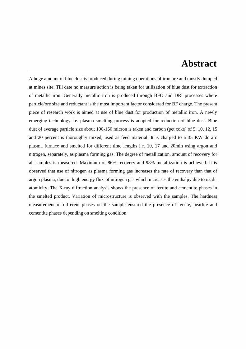
Abstract
A huge amount of blue dust is produced during mining operations of iron ore and mostly dumped
at mines site. Till date no measure action is being taken for utilization of blue dust for extraction
of metallic iron. Generally metallic iron is produced through BFO and DRI processes where
particle/ore size and reductant is the most important factor considered for BF charge. The present
piece of research work is aimed at use of blue dust for production of metallic iron. A newly
emerging technology i.e. plasma smelting process is adopted for reduction of blue dust. Blue
dust of average particle size about 100-150 micron is taken and carbon (pet coke) of 5, 10, 12, 15
and 20 percent is thoroughly mixed, used as feed material. It is charged to a 35 KW dc arc
plasma furnace and smelted for different time lengths i.e. 10, 17 and 20min using argon and
nitrogen, separately, as plasma forming gas. The degree of metallization, amount of recovery for
all samples is measured. Maximum of 86% recovery and 98% metallization is achieved. It is
observed that use of nitrogen as plasma forming gas increases the rate of recovery than that of
argon plasma, due to high energy flux of nitrogen gas which increases the enthalpy due to its di-
atomicity. The X-ray diffraction analysis shows the presence of ferrite and cementite phases in
the smelted product. Variation of microstructure is observed with the samples. The hardness
measurement of different phases on the sample ensured the presence of ferrite, pearlite and
cementite phases depending on smelting condition.
List of figures
Figure 2.1 Typical plasmas characterized by their energies and densities.
Figure 2.2 Temperature and energy relationship of various plasma gases.
Figure 2.3 Schematic diagrams of transferred and non-transferred plasma torches.
Figure 3.1 Skeleton of methodology.
Figure 3.2 DC arc plasma setup.
Figure 4.1 X-Ray diffractogram of blue dust raw powder.
Figure 4.2 Percentage of recovery of samples smelted by argon and nitrogen plasma
Figure 4.3 Degree of metallization of samples smelted by argon and nitrogen plasma
Figure 4.4 Optical Micrograph of smelted blue dust + 0% coke by Nitrogen plasma.
Figure 4.5 Optical Micrograph of smelted blue dust + 5% coke by Nitrogen Plasma.
Figure 4.6 Optical micrograph of smelted blue dust + 10% coke by Nitrogen Plasma.
Figure 4.7 Optical micrograph of smelted blue dust + 12% coke by Nitrogen Plasma.
Figure 4.8 Optical micrograph of smelted blue dust + 15% coke by Nitrogen Plasma.
Figure 4.9 Optical micrograph of smelted blue dust + 20% coke by Nitrogen Plasma.
Figure 4.10 Optical micrograph of smelted blue dust + 5% coke by Argon Plasma.
Figure 4.11 Optical micrograph of smelted blue dust + 10% coke by Argon Plasma.
Figure 4.12 Optical micrograph of smelted blue dust + 12% coke by Argon Plasma.
Figure 4.13 Optical micrograph of smelted blue dust + 15% coke by Argon Plasma.
Figure 4.14 Optical micrograph of smelted blue dust + 20% coke by Argon Plasma.
Figure 4.15 X-Ray diffractogram of smelted blue dust + 0% coke by Nitrogen plasma.
Figure 4.16 X-Ray diffractogram of smelted blue dust + 5% coke by Nitrogen plasma.
Figure 4.17 X-Ray diffractogram of smelted blue dust + 10% coke by Nitrogen plasma.
Figure 4.18 X-Ray diffractogram of smelted blue dust + 12% coke by Nitrogen plasma.
Figure 4.19 X-Ray diffractogram of smelted blue dust + 15% coke by Nitrogen plasma.
Figure 4.20 X-Ray diffractogram of smelted blue dust + 20% coke by Nitrogen plasma.
Figure 4.21 X-Ray diffractogram of smelted blue dust + 5% coke by Argon plasma.
Figure 4.22 X-Ray diffractogram of smelted blue dust + 10% coke by Argon plasma.
Figure 4.23 X-Ray diffractogram of smelted blue dust + 12% coke by Argon plasma.
Figure 4.24 X-Ray diffractogram of smelted blue dust + 15% coke by Argon plasma.
Figure 4.25 X-Ray diffractogram of smelted blue dust + 20% coke by Argon plasma.

List of tables
Table 3.1 Composition, plasma gas and operating parameters.
Table 4.1 Chemical composition blue dust.
.

1 | P a g e
Chapter 1
INTRODUCTION
• Research Background • Objectives of Research
2 | P a g e
Chapter 1
Introduction
1.1 RESEARCH BACKGROUND
In the present era, embryonic technologies comprehends some of the most conspicuous on-
going progresses, improvements, and research to expand extraction of iron by using different
types of modern technology to achieve an economic process that suits best. Critical components
and complex operating conditions are the key factors for reduced utility of input feed material
and energy. The need for higher efficiency and productivity across the entire spectrum of iron
and steel making industries has ensured that most economic, least time consuming and simplified
process is yet to be optimized.
Currently iron and steel making is dominated by the route comprising a blast furnace and a basic
oxygen converter; meanwhile Ferro alloys are formed in submerged-arc electric smelting
furnaces. The elevated temperatures and thermodynamic energy required by the process can be
obtained in two ways; by combustion, or by the use of electrical power. Production on reliable
source of high quality raw materials such as sinter, pellets, and coke are the principal economic
constraints of the process. In addition the inflexibility of the process capacity, high capital and
operation costs, and energy lost in between stages still a prominent aspect for reduced economy.
Extraction of pig iron through this route persists some major cons cited below, which can be
considered with importance;
Energy losses in iron oxide feed preparation
Critical cost machineries : iron oxide feed, energy, and capital costs
Residence time in the reactor
Inflexibility of process: cannot be shut down and resumed easily.
Apart from all these there persists another foremost problem in size of iron ore to be processed.
Extensive mechanized mining and advanced beneficiation methods to meet the oxide feed
requirements of Blast furnace, Direct Reduction and Smelting Reduction processes are resulting
in generation of macro and micro fines not only in various mine sites but also crushing units,
washing units, and many more. However a part of the fines, mostly macro ones, in the
agglomerated form, that is either as .sinter or pellet have found use in various iron making
processes, the difficulty still persist with utilization of micro fines.
3 | P a g e
Blue dust is a high grade soft hematite ore fines containing more than 96 % Fe2O3 enormously
available today. For transportation problem and environmental hazardous factor concerned, these
high grade iron ore fines are getting dumped at mine sites. Utilization of these iron oxide fines
and applicability of the same for the blast furnace feed and powder metallurgy is an approach for
production of value added product being wasted.
Keeping above facts in sight, application of plasma technology seems to be an emerging
alternative for iron and steel making industries for many of its advantages over any other
processes. Maximum utilization of heat energy at extreme temperatures is only feasible by
plasma that leads to faster rate of reaction with economy. For its wide range of melting
material, independency of size and composition of feed, flexibility of controlled operating
parameters and purity level in final product has been drawing attention of researchers in the
present era.
In general plasma is used as heat source instead of reductant itself as % of degree of reduction
lags behind when utilized as reductant.
The selection of type of plasma and preferred operating parameters along with type of reductant
is a crucial factor which needs to be considered sensibly in relation to the treating of material.
The wrong choice can affect both, trouble shooting and also processing costs. Criteria for
selection must be based on answering many questions, which comprises;
i. Type of reducing agent (carboneous or any other)
ii. Type of plasma forming gas (inert, self-reducing self-burning or helps in burning)
iii. Type of process (melting, smelting or smelting reduction)
iv. Process duration
v. Process environment (open air, inert or vacuum)
vi. Feed rate
vii. Power control
4 | P a g e
1.2 OBJECTIVES OF RESEARCH
The objective of the current study is as follows:
To explore the extraction of iron from blue dust by varying % of reductant
added, types of plasma forming gas used and smelting duration.
To determine extent of degree of metallization and recovery by altering
above parameters.
X-ray diffraction studies to find out the presence of formation of different
phases.
Optical micrographic studies.
Measurement of hardness.
5 | P a g e
Chapter 2
Literature Survey
• Introductory statement • Plasma • Types of plasma • Plasma chemistry • Generation of plasma
• Application of plasma • Advantages of plasma over conventional processes • Iron making Processes
• Reduction kinetics • Application of plasma technology in smelting and
reduction
6 | P a g e
Chapter 2
Literature Survey
2.1 INTRODUCTORY STATEMENT This chapter refers to the literature survey of the area of plasma processing of blue dust.
This describes the most interesting topic plasma technology and its applicability on extractive
metallurgy. It gives a sound description of generation of plasma and its different characteristics.
The plasma chemistry under various conditions has been reviewed along with the corresponding
research when implemented to a variety of minerals and materials. Blue dust is still a challenge
for conventional iron making industries through blast furnace for its fineness. Some of special
features of plasma technology like achieving high temperature with liberation of huge heat
energy, faster rate of reaction and accessibility to range of materials are of interest of this work.
2.2 Plasma It is not unusual to refer plasma as the fourth state of matter as it is an ionized gas
comprised of molecules, atoms, ions (in their ground or in various excited states), electrons and
photons [1,2,4]. Plasma possesses a unique property known as quasi-neutrality, since plasma is
electrically neutral.
In contrast to an ordinary gas, plasma encloses free electric charges that are commonly produced
from the gas itself by a variety of ionization processes. In a steady-state situation, the rate of
ionization in the plasma is balanced by the rate of recombination. Depending upon the energy
content of the plasma, the degree of ionization may be so high that virtually no neutral particles
are left, i.e. plasma becomes fully ionized.
2.3 Types of plasma Since plasma is a broad topic as concerned, all together plasmas are classified into three
main categories [1, 4]:
CTE plasmas (Complete thermodynamic equilibrium)
LTE plasmas (local thermodynamic equilibrium)
Non-LTE plasmas (nonlocal thermodynamic equilibrium)
Among above three types CTE plasmas are used for thermonuclear fusion experiments. The
latter two types are used as laboratory plasmas and also implemented for industrial purposes like
MINTEK, South Africa.
7 | P a g e
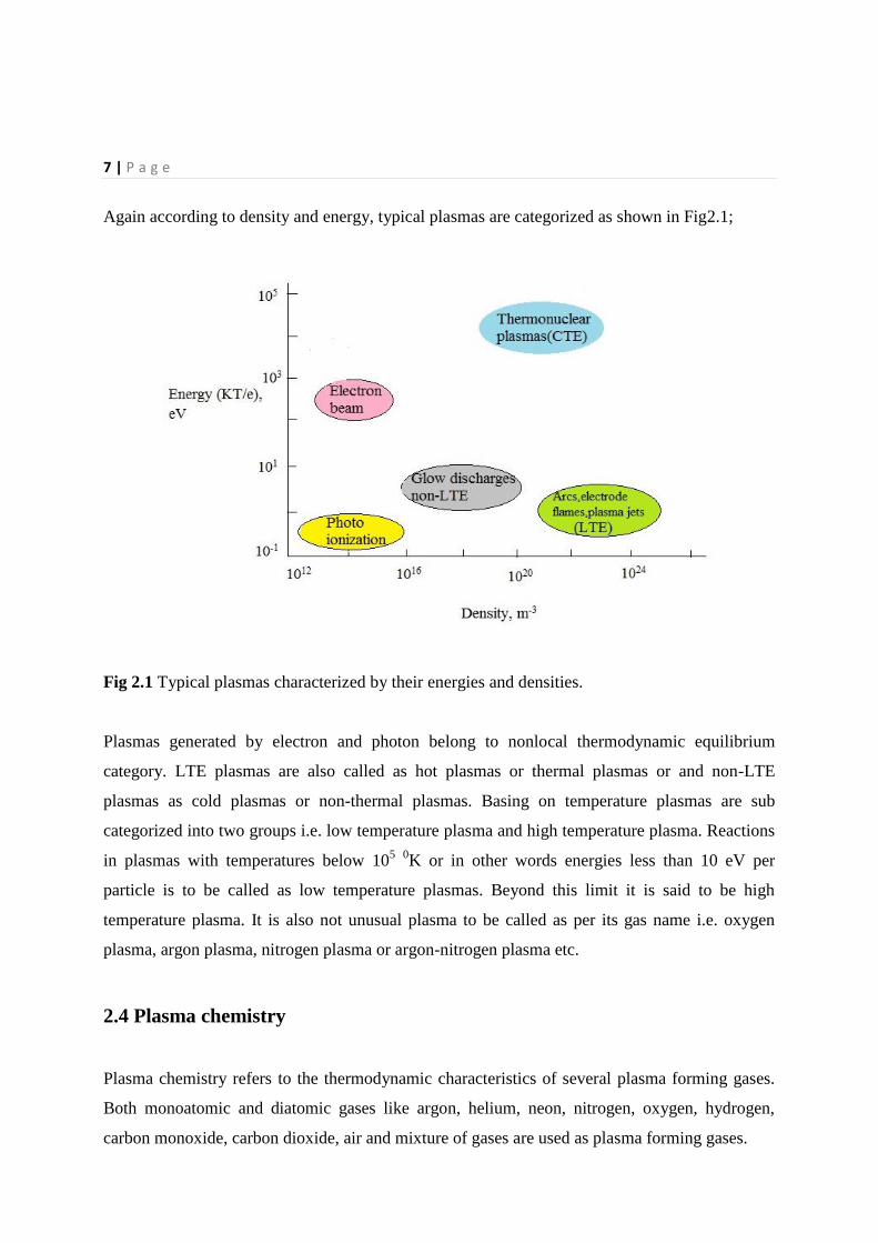
Again according to density and energy, typical plasmas are categorized as shown in Fig2.1;
Fig 2.1 Typical plasmas characterized by their energies and densities.
Plasmas generated by electron and photon belong to nonlocal thermodynamic equilibrium
category. LTE plasmas are also called as hot plasmas or thermal plasmas or and non-LTE
plasmas as cold plasmas or non-thermal plasmas. Basing on temperature plasmas are sub
categorized into two groups i.e. low temperature plasma and high temperature plasma. Reactions
in plasmas with temperatures below 105
0K or in other words energies less than 10 eV per
particle is to be called as low temperature plasmas. Beyond this limit it is said to be high
temperature plasma. It is also not unusual plasma to be called as per its gas name i.e. oxygen
plasma, argon plasma, nitrogen plasma or argon-nitrogen plasma etc.
2.4 Plasma chemistry
Plasma chemistry refers to the thermodynamic characteristics of several plasma forming gases.
Both monoatomic and diatomic gases like argon, helium, neon, nitrogen, oxygen, hydrogen,
carbon monoxide, carbon dioxide, air and mixture of gases are used as plasma forming gases.
8 | P a g e
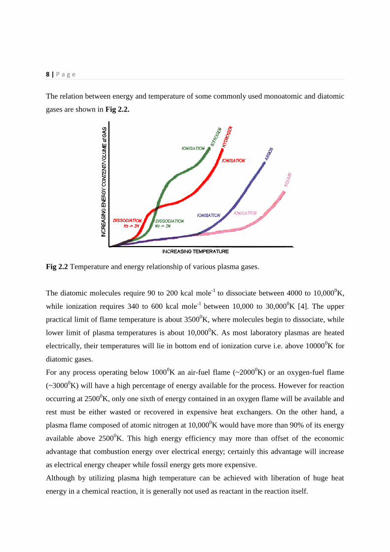
The relation between energy and temperature of some commonly used monoatomic and diatomic
gases are shown in Fig 2.2.
Fig 2.2 Temperature and energy relationship of various plasma gases.
The diatomic molecules require 90 to 200 kcal mole-1
to dissociate between 4000 to 10,0000K,
while ionization requires 340 to 600 kcal mole-1
between 10,000 to 30,0000K [4]. The upper
practical limit of flame temperature is about 35000K, where molecules begin to dissociate, while
lower limit of plasma temperatures is about 10,0000K. As most laboratory plasmas are heated
electrically, their temperatures will lie in bottom end of ionization curve i.e. above 100000K for
diatomic gases.
For any process operating below 10000K an air-fuel flame (~2000
0K) or an oxygen-fuel flame
(~30000K) will have a high percentage of energy available for the process. However for reaction
occurring at 25000K, only one sixth of energy contained in an oxygen flame will be available and
rest must be either wasted or recovered in expensive heat exchangers. On the other hand, a
plasma flame composed of atomic nitrogen at 10,0000K would have more than 90% of its energy
available above 25000K. This high energy efficiency may more than offset of the economic
advantage that combustion energy over electrical energy; certainly this advantage will increase
as electrical energy cheaper while fossil energy gets more expensive.
Although by utilizing plasma high temperature can be achieved with liberation of huge heat
energy in a chemical reaction, it is generally not used as reactant in the reaction itself.
9 | P a g e
2.5 Generation of Plasma
Thermal arc plasmas are generated by striking an electric arc between two or more electrodes.
They are characterized by high current densities (greater than 100 A/cm2) and are more luminous
than other types of discharges, especial1y when operated, at atmospheric pressure and above.
Thermal arcs can be initiated in several ways. Two common methods are electrode contact which
produces a short circuit, or pre-ionization of the gap between electrodes by a high frequency
spark. The cathode must be heated beyond 3500 K, at which point thermionic emission of
e1ectrons begins, generating the charge carriers that create the plasma state [2]. Cold cathodes
are cylindrical and made of heavily cooled copper, Iron, or copper alloy whi1e high temperature
cathodes are usually rod-shaped and made of thorium, tungsten or graphite.
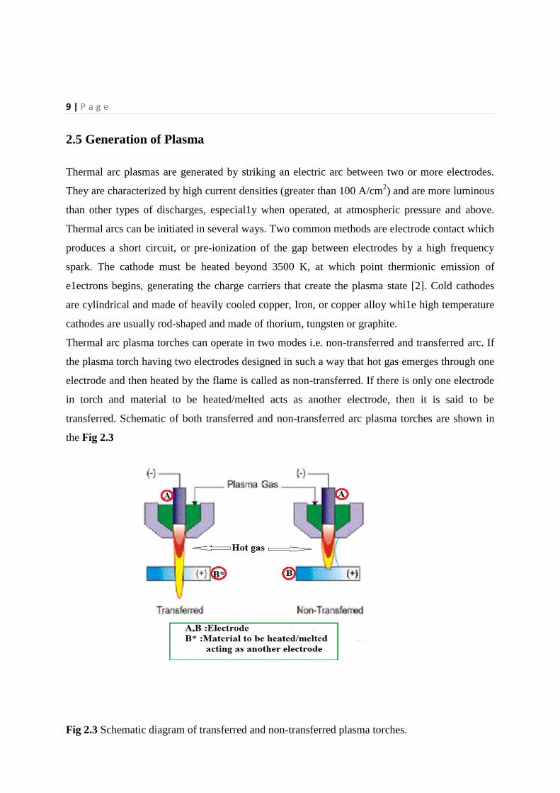
Thermal arc plasma torches can operate in two modes i.e. non-transferred and transferred arc. If
the plasma torch having two electrodes designed in such a way that hot gas emerges through one
electrode and then heated by the flame is called as non-transferred. If there is only one electrode
in torch and material to be heated/melted acts as another electrode, then it is said to be
transferred. Schematic of both transferred and non-transferred arc plasma torches are shown in
the Fig 2.3
Fig 2.3 Schematic diagram of transferred and non-transferred plasma torches.
10 | P a g e
2.6 Application of plasma In last two decades for researchers plasma has claimed to be an emerging solution to a
numerous processes due its some unique features and hence implemented in various sectors.
Plasma finds significant industrial applications as following processes [3];
Melting
Smelting
Smelting and reduction
Remelting and refining
Spark plasma sintering
Surface modification
Surface coating
Past research works describes the feasibility of plasma in above cited processes were
successful [2, 3, 5, 7]. For reaching high temperature in a reaction, plasma is being preferred
and its flexibility over operating parameters along with acceptance of all most all materials
and size and shape of material has raised the importance of utilizing plasma [1].
2.7 Advantages of plasma technology over conventional processes Although there are lot many advantageous aspects behind the utilization of plasma, some of the
important features are outlined below.
High efficiency
Since huge amount of energy in the form of heat is available by utilization of plasma, high
throughput can be achieved.
Long range of melting materials
Since high temperature can be achieved in a reaction by using plasma, all most all materials can
be melted in this process. Although its commercial use to melt and process metals is well known,
the method is less well known as a method of melting glass [6].
Feed capability
This process is independent of size, shape and composition of feed material. This ability draws
attention of researchers and industries for utilization of high grade fine particles that was a
challenge to be processed and dumped due to environmental hazards [15].
Transient process
Due to release of huge heat energy that a particular reaction requires at a particular temperature,
plasma stands ahead of any other process to respond the changes in shorter period [6].
11 | P a g e
High energy fluxes
Higher temperatures with extreme jet velocities and greater thermal conductivities of plasma
gases are the key factors that results in high energy fluxes. Smaller furnace dimensions with high
smelting capacity are an exceptional aspect of using plasma. [1]
Independent energy source
Flexibility of control over feed rate and power independently and input power is not limited by
electrical conductivity of feed material to be melted or smelted. Hence greater freedom of choice
with respect to charge composition is available by using plasma.
Gas flow rate control
Unlike combustion systems the gas flow rate, temperature and energy input are not
interdependent and gas flow rate and temperature can be controlled separately irrespective of
energy input.
Gas environment control
Energy can be provided to system with desired oxygen potential in order to ensure oxidizing,
reducing or inert gas conditions independently without taking temperature into account.
Electrical energy intensive
Minimization of the usage of fossil fuel energy and conserve fossil fuel can be made.
Purity level of output
Purity level of final product through plasma processing is very high [23].
Economic process
As output heat energy dominates input combustion energy plasma processing ascertains to be an
economic as compared to any other conventional processes. [1]
2.8 Iron making processes
Importance of traditional iron making through blast furnace has been declined due to lots of
problems associated, initial investment cost, availability of huge raw feed and complexity in
stages. Now a day’s production of iron is made in two different forms [5]:
a) Direct reduced iron(DRI)
b) Hot metal(via smelting reduction)
2.8.1Direct reduced iron
In this process iron ore (fines, lumps or pellets) is reduced to the solid-state either by solid or
gaseous reducing agents giving rises to a solid final product.
12 | P a g e
Shaft furnaces, fluidised beds or retorts are used as reactors in case of gas based direct reduction
processes. In other hand rotary kilns, rotary hearth furnaces or multi-hearth furnaces are
implemented in case of direct reduction processes.
Pros and cons of DRI over BF iron making
Some of advantageous features of DRI are listed below.
i. Independency on coking coal
ii. Smaller module size
iii. Lower initial capital investment
iv. Lesser complexity
Simultaneously there are some draw backs of DRI as well.
i. Final product being solid requires melting for steel making
ii. Smaller module size also affects economy
iii. Productivity lower
Uses of DRI
Direct reduced iron finds its utilization in following places.
BOF(Basic oxygen furnaces)
EAF(Electric arc furnaces)
Induction furnaces
Open hearth furnaces
Ladle furnaces
2.8.2 Smelting and reduction (hot metal)
Smelting and reduction involves both reduction and smelting. Basically SR is a two-step
operation to obtain liquid hot metal. Lump ores, ore fines, wastes all can be taken as oxide feed
in case of smelting reduction. SR may be classified into two categories according to the number
of stages involved i.e. single-stage and two stage process. In single stage both reduction and
melting occurs in a single reactor where as in case of two-stage two reactors involved for pre-
reduction and smelting reduction operations. Further SR processes are classified in terms of
smelting furnace used i.e. basic oxygen furnace (BOF), blast furnace hearth (BFH), blast furnace
enhancement (BOE), open hearth and electric arc furnace (EAF). Some of several SR processes
developed according to the type of furnace involved are cited below.
13 | P a g e
Basic oxygen furnace(BOF) : Corex, Finex, Hismelt, Dios, Combismelt, Coin
Basic furnace hearth (BFH) : Tecnored, Kawasaki SR, Plasmasmelt
Blast furnace enhancement (BFE) : Piragos, BSC Oxy-coal
Open hearth (OH) : Ausmelt, Rosmelt
Electric arc furnace (EAF) : Inred, Elred
2.9 Reduction kinetics
Basically reduction of iron ore to iron is a three-step conversion process. In carbothermic
reduction, carbon and temperature plays the important role.
Reduction of Iron ore by Carbon and carbon monoxide follows below given reactions [5,24];
Fe2O3→Fe3O4→FeO→Fe
3Fe2O3 + C → 2 Fe3O4 + CO
Fe3O4 + 4C → 3 Fe + 4CO
Fe0 + C → Fe + CO
C + CO2 → 2CO
3Fe2O3 + CO → 2Fe3O4 + CO2
Fe3O4 + CO → 3FeO + CO2
FeO + CO → Fe + CO2
2.10 Plasma smelting and reduction
Past research shows smelting and reduction of different materials were fruitfully done by
utilizing plasma technology. Some of those precious works that led to be an alternative solution
for improved economy are mentioned below.
Carbothermic reduction and smelting of Ta2O5 with argon plasma-arc heating and hydrogen-
argon plasma-arc melting was investigated [7]. Ductile Ta metal with greater purity level under
different conditions was inspected.
Beach sand collected from east cost of India containing ilmenite was plasma smelted with
petroleum coke as reductant [9]. TiO2 containing slag and pig iron were obtained as final
product. Effect of reductant percentage, input power and slag characteristics had been studied.
Carbothermic reduction and smelting of niobium pentoxide was done by using dc extended arc
plasma reactor [10]. Final product obtained when examined found to be more than 97% Nb with
14 | P a g e
86% overall recovery. Nb along with carbon in the form of carbide was detected in
characterization.
Plasma smelting of red mud a by-product of Bayer process was done to produce pig iron
effectively [17]. Extended plasma arc reactor was used for the smelting operation. Study of
different process parameters were observed and optimized.
Ilmenite was treated by thermal plasma with methane and ammonia as plasma forming gases
[10]. High concentration of methane favoured in the formation of iron as well as titanium nitride
and carbonitride.
Carbothermic reduction and smelting of silimenite was carried out in in transferred arc reactor
with nitrogen as plasma gas [20]. Conversion of silimenite to Mullite, aluminium, silicon and
silicon carbide was investigated.
Addition of zirconia in carbothermic reduction and smelting of iron ore fines by extended arc
plasma was investigated [22]. Utilization of zirconia gave rise to nodularization of graphite in
cast iron that possesses very good mechanical property.
Blue dust was smelted in extended arc plasma with coal and coke as reductants [23]. Magnesium
was added in the melt stage. Purer pig iron having low content of sulphur and other tramp
elements was obtained that can be comparable to SG iron.
15 | P a g e
Chapter 3
Experimental set up and
Methodology
Introduction
Characterization of raw blue dust
Preparation of feed material
Smelting and reduction in DC arc plasma furnace
Characterization of smelted and reduced product
Degree of metallization
16 | P a g e
Chapter 3
Experimental set up and Methodology
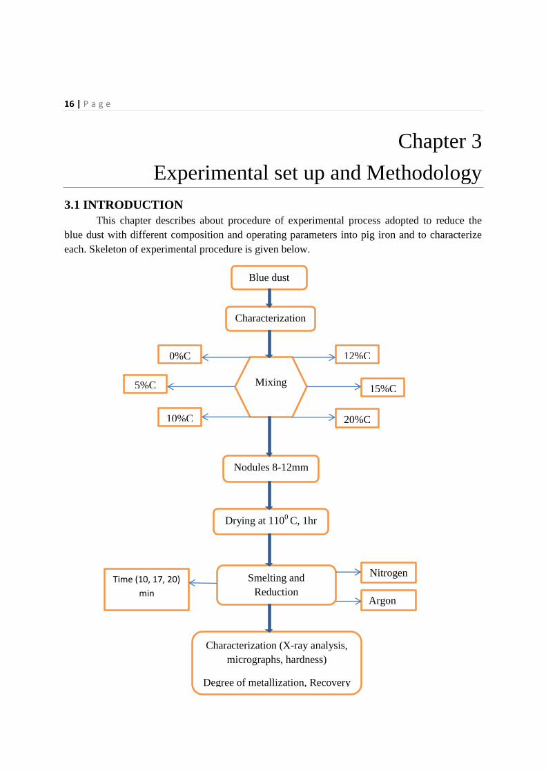
3.1 INTRODUCTION This chapter describes about procedure of experimental process adopted to reduce the
blue dust with different composition and operating parameters into pig iron and to characterize
each. Skeleton of experimental procedure is given below.
Blue dust
Mixing
Nodules 8-12mm
Drying at 1100
C, 1hr
Characterization
Smelting and
Reduction
Characterization (X-ray analysis,
micrographs, hardness)
Degree of metallization, Recovery
0%C
5%C
10%C
15%C
12%C
20%C
Nitrogen
Argon
Time (10, 17, 20)
min
17 | P a g e
Before smelting and reduction, some basic process required for feed material i.e. compositional
analysis, X-ray diffraction studies, preparation of nodules, drying. After plasma smelting, the
final product have been subjected to a series of characterization test i.e. microstructural
characterization of the surfaces, X-ray diffraction studies, degree of metallization studies,
calculation of percentage of recovery, micro-hardness measurement. Each process is briefly
described here.
3.2 Characterization of raw blue dust
3.2.1 Compositional analysis
The compositional analysis of raw blue dust powder was carried out in the export
chemical unit of DISIR, Rajgangpur, India by preparing suitable stock solution and by following
wet chemical analysis. For detection of weight fraction of presence of each element/oxide
separate tests were followed. Loss on ignition percentage was determined by heating the raw
blue dust at 10000 C for 1hour and calculating as following;
LOI in % = (Weight loss of material due to heating/Initial weight of material taken) × 100
3.2.2 X-ray diffraction studies
X-ray diffraction technique was used to detect the different phases presents in the raw
sample collected from DISIR, Rajgangpur, India. XRD analysis was done by using X-Pert MPD
system (PAN Analytical). Here Ni-filtered Cu-Kα radiation used in X-ray diffractometer. The d-
spacing values obtained from XRD patterns were matched with the characteristic d-spacing of all
possible values from JCPDS cards to obtain the various X-ray peaks.
3.3 Preparation of feed material
Six different weight percentages of blue dust and petroleum coke were taken separately and
mixed properly. Nodules of size 8-12 mm were prepared by adding water to mixed compositions.
All the prepared nodules were then dried at 1100
C for removal of moisture and to strengthen the
same in order to minimize loss during feeding.
18 | P a g e
3.4 Smelting in DC arc plasma furnace
3.4.1 DC arc plasma furnace
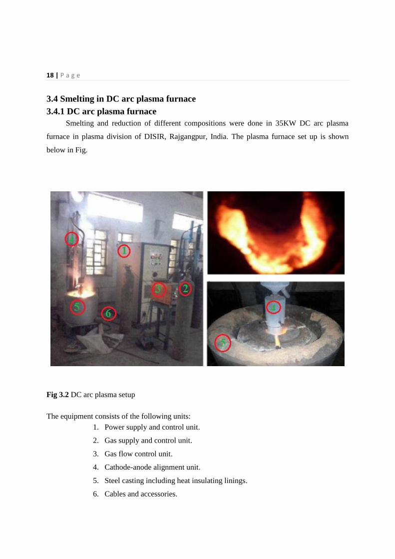
Smelting and reduction of different compositions were done in 35KW DC arc plasma
furnace in plasma division of DISIR, Rajgangpur, India. The plasma furnace set up is shown
below in Fig.
Fig 3.2 DC arc plasma setup
The equipment consists of the following units:
1. Power supply and control unit.
2. Gas supply and control unit.
3. Gas flow control unit.
4. Cathode-anode alignment unit.
5. Steel casting including heat insulating linings.
6. Cables and accessories.
19 | P a g e
On top of the reactor plasma torch is attached in the downward direction. The plasma torch
contains a hollow cylindrical graphite crucible with 145mm outer diameter, wall thickness 15mm
and 300mm high that serves as the anode. Hollow graphite rod of 400mm long and 5mm inner
and 35mm outer diameter serves as the cathode. Graphite rod end is tapered to a conical shape
for superior electron emission. Hollow structure of cathode has designed to have provisions for
gas flow. The material to be processed was placed in the anode crucible bed and the arc was
initiated by shorting the cathode and the crucible bottom wall (graphite plate). The arc length
was increased by raising the cathode rod up suitably within the crucible to heat the charge placed
in the crucible. Power supply unit and power control unit is designed to vary necessary voltage
and current and easy control of this helps in smooth conducting experiments. Voltage and current
can be altered over a range of 0-50V and 0-300A respectively. Gas supply unit comprises of
types of plasma forming gases i.e. hydrogen, oxygen, argon and nitrogen. Besides these gases
helium, neon, carbon monoxide, carbon dioxide and also mixture of above can be utilized as
plasma forming gas. Gas flow control consisting of digital indicators helps in not only measuring
gas flow rate but also governing suitable flow of gases as per experiment performed and stands
as a key parameter. Gas flow rate can be varied from 0-2.5 LPM. Heat insulating materials are
placed in between steel casting and reaction chamber.
3.4.2 Smelting and reduction operation
This is consisting of several prerequisite steps to be done before feeding samples into the
reaction chamber. Initially crucible was cleaned in order to avoid any other material contained in
crucible to be reacted with samples. Hollow tapered graphite rod was fitted in such a way that it
points towards centre of reaction chamber. After checking no leakage in crucible it was placed
the space provided in steel casting. Bubble alumina was poured in spacing between reaction
chamber and reaction chamber that acts as insulating medium of heat. Power supply then
provided and proper arcing between cathode and anode was tested. Gas supply is then connected
to the cathode passage and plasma forming gas was purged into the reaction chamber for
1minute to displace atmospheric air. After that power supply and plasma forming gas supply
both supplied simultaneously and required voltage and current maintained. Then sample feed
were poured into the hot reaction chamber as per our requirement. Composition, type of plasma
forming gases and operating parameters of each sample are cited below in table 3.
20 | P a g e
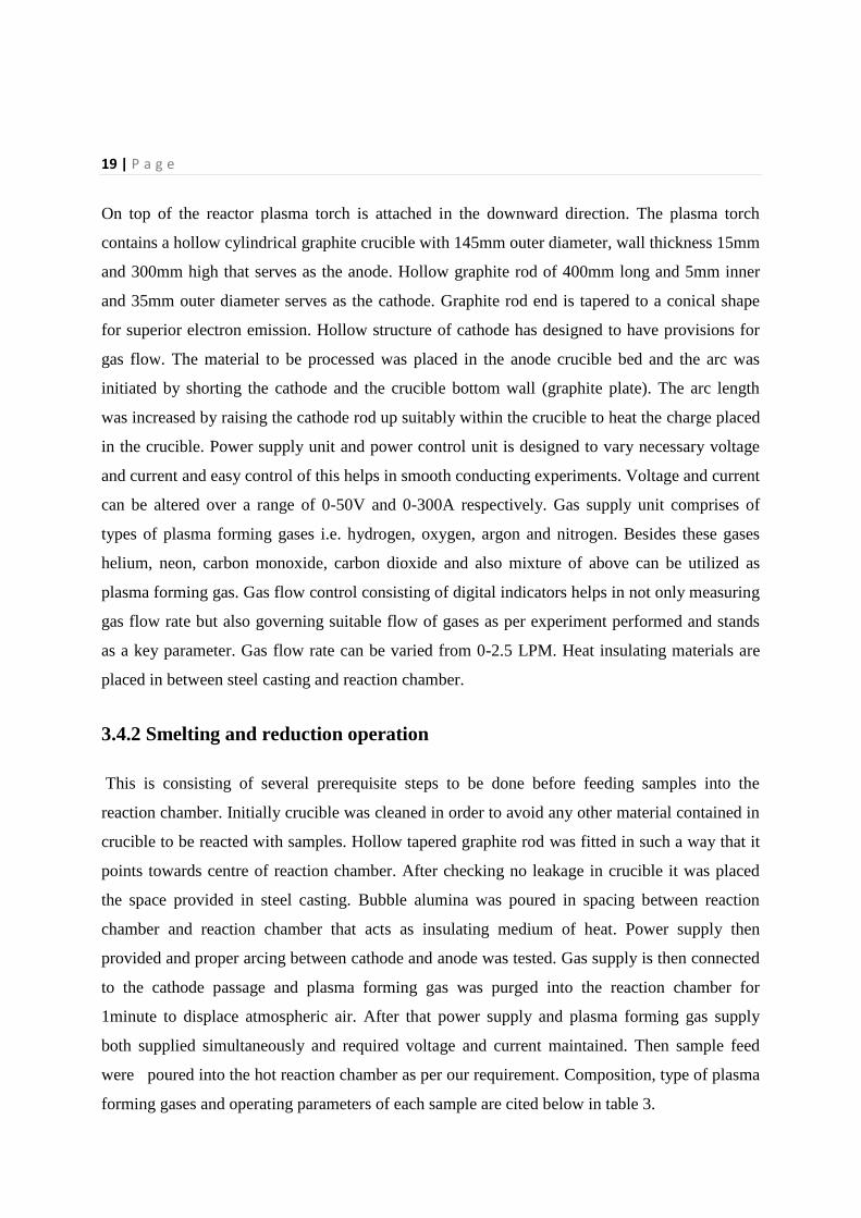
Table 3.1 Composition, plasma gas and operating parameters
Sample no.
% C mixed with
blue dust
Smelting duration (min)
Sample weight (gm.)
Plasma forming gas : Nitrogen
Gas flow rate : 2.5 lpm
Operating parameter : 50V, 300A
1 0 17 300
2 5 17 295
3 10 17 301
4 12 10 302
5 15 17 295
6 20 17 273
Plasma forming gas : Argon
Gas flow rate : 2.5 lpm
Opearating parameter : 50V, 300A
7 5 20 297
8 10 17 300
9 12 17 268
10 15 17 296
11 20 17 270
21 | P a g e
3.5 Characterization of smelted product After successful smelting of samples in the furnace, final product was cooled in the furnace
itself. Then those bulk products were removed from crucible and appropriate samples were
prepared for characterization.
3.5.1X-Ray Diffraction Studies X-ray diffraction technique was used to identify the different phases presents in the smelted
product. XRD analysis was done by using Philips X-Pert MPD system (PAN Analytical). Here
Ni-filtered Cu-Kα (1.54) radiation used in X-ray diffractometer. D-spacing values obtained from
XRD patterns were compared with the characteristic d-spacing of all possible values from
JCPDS cards to obtain the various X-ray peaks.
3.5.2Optical microscopic studies Since final product obtained was in irregular shape, crushing those into 5-10mm size and
mounting in cold setting resin was essential before following polishing stages. After proper
polishing micrographs were studied by using Zeusius light emission electron microscope under
suitable magnification. Area fraction analysis was done for all samples by using Axio vision
software of version 4.8.
3.6 Hardness
Vickers hardness was performed in a LECO micro hardness tester LM248AT by using suitable
load.
3.7 Degree of metallization
By taking 1gm powdered sample of each, preparing proper stack solution and following wet
chemical analysis percentage of metallic Fe and percentage of total Fe were obtained. Metallic
Fe includes sum of metal and metal carbides whereas total Fe counts sum of metal, metal
carbides and metal oxides. Degree of metallization calculated as following:
Degree of metallization = (Metallic Fe) / (Total Fe)
22 | P a g e
Chapter 4
Results and Discussion
Introduction
Characterization of raw blue dust
Recovery
Degree of metallization
Characterization of final product
Micro hardness
Discussion
23 | P a g e
CHAPTER 4 RESULTS AND DISCUSSION
4.1 INTRODUCTION Smelting and reduction of blue dust was carried out in 35 KW dc arc plasma reactor by
using petroleum coke as reductant. By using argon and nitrogen as plasma forming gases with
different composition were taken for this purpose. Characterization of raw blue dust as well as
final product was done and smelting and reduction performances of different feeds are
investigated in terms of degree of metallization and recovery. The results presented and
discussed in this chapter.
4.2 Characterization of raw blue dust
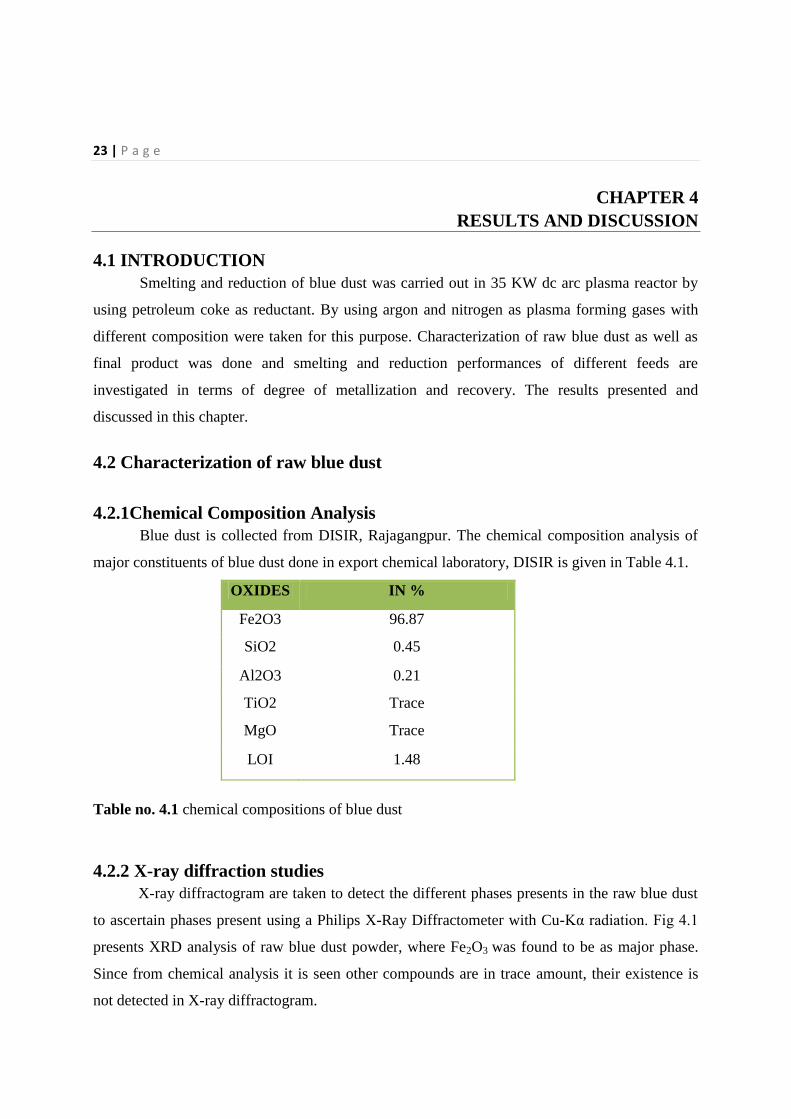
4.2.1Chemical Composition Analysis
Blue dust is collected from DISIR, Rajagangpur. The chemical composition analysis of
major constituents of blue dust done in export chemical laboratory, DISIR is given in Table 4.1.
OXIDES IN %
Fe2O3 96.87
SiO2 0.45
Al2O3 0.21
TiO2 Trace
MgO Trace
LOI 1.48
Table no. 4.1 chemical compositions of blue dust
4.2.2 X-ray diffraction studies
X-ray diffractogram are taken to detect the different phases presents in the raw blue dust
to ascertain phases present using a Philips X-Ray Diffractometer with Cu-Kα radiation. Fig 4.1
presents XRD analysis of raw blue dust powder, where Fe2O3 was found to be as major phase.
Since from chemical analysis it is seen other compounds are in trace amount, their existence is
not detected in X-ray diffractogram.
24 | P a g e
10 20 30 40 50 60
0
50
100
150
200
250
2 (Deg)
Inte
nsi
ty (
a.u
.)
Fe2O
3
(
012)
(
110)
(
113)
(
024)
(
116)
(
018)
(
104)
Figure 4.1 X-Ray diffractogram of blue dust raw powder.
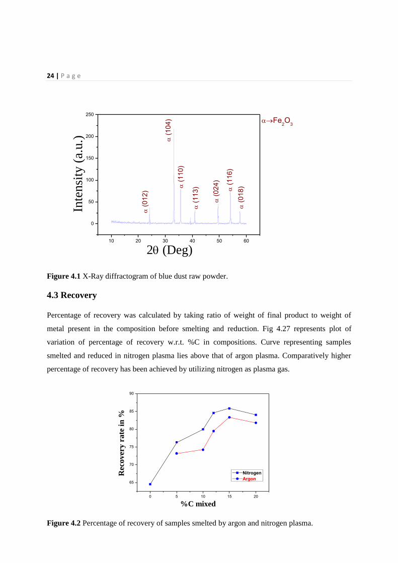
4.3 Recovery
Percentage of recovery was calculated by taking ratio of weight of final product to weight of
metal present in the composition before smelting and reduction. Fig 4.27 represents plot of
variation of percentage of recovery w.r.t. %C in compositions. Curve representing samples
smelted and reduced in nitrogen plasma lies above that of argon plasma. Comparatively higher
percentage of recovery has been achieved by utilizing nitrogen as plasma gas.
0 5 10 15 20
65
70
75
80
85
90
Nitrogen
Argon
Rec
ov
ery
ra
te i
n %
%C mixed
Figure 4.2 Percentage of recovery of samples smelted by argon and nitrogen plasma.
25 | P a g e
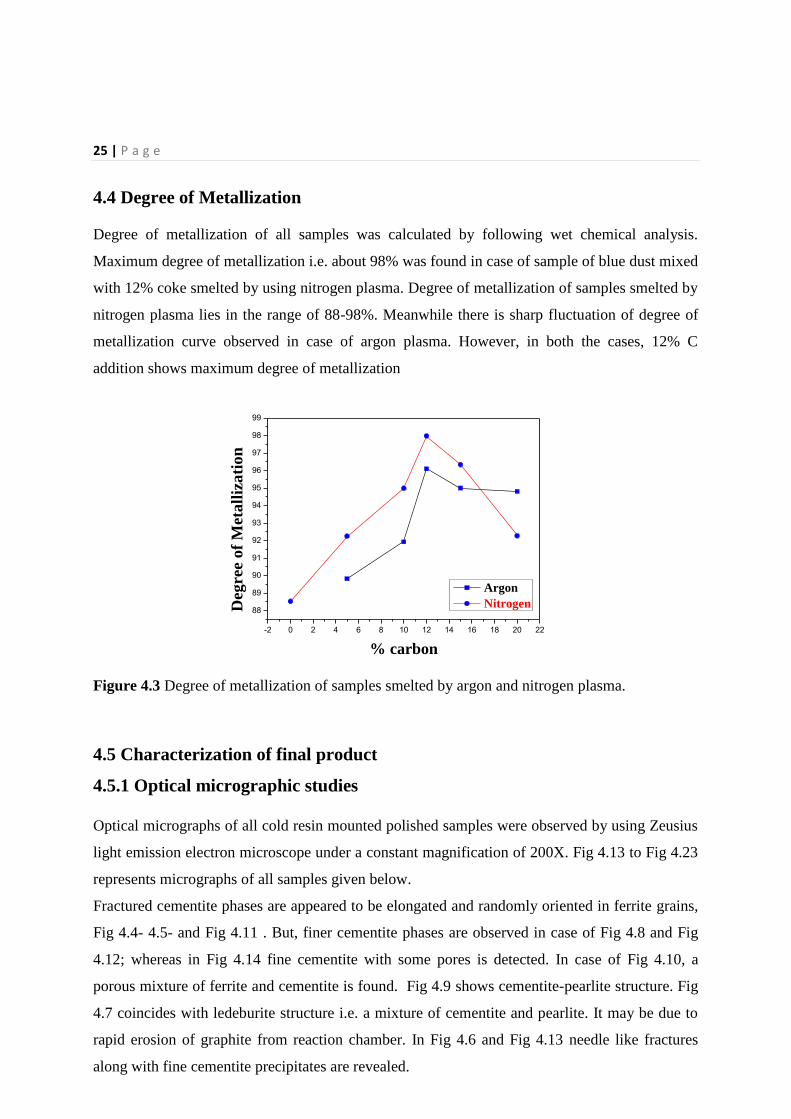
4.4 Degree of Metallization
Degree of metallization of all samples was calculated by following wet chemical analysis.
Maximum degree of metallization i.e. about 98% was found in case of sample of blue dust mixed
with 12% coke smelted by using nitrogen plasma. Degree of metallization of samples smelted by
nitrogen plasma lies in the range of 88-98%. Meanwhile there is sharp fluctuation of degree of
metallization curve observed in case of argon plasma. However, in both the cases, 12% C
addition shows maximum degree of metallization
-2 0 2 4 6 8 10 12 14 16 18 20 22
88
89
90
91
92
93
94
95
96
97
98
99
Deg
ree
of
Met
all
iza
tio
n
% carbon
Argon
Nitrogen
Figure 4.3 Degree of metallization of samples smelted by argon and nitrogen plasma.
4.5 Characterization of final product
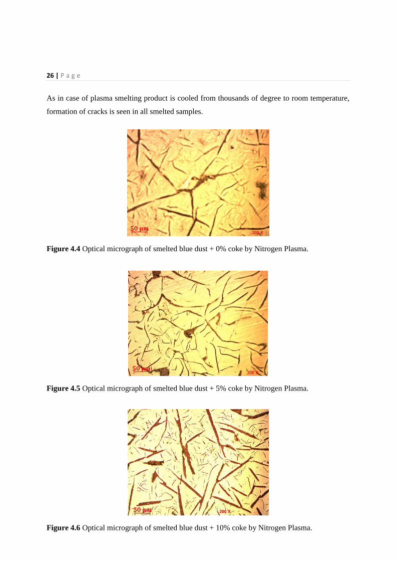
4.5.1 Optical micrographic studies
Optical micrographs of all cold resin mounted polished samples were observed by using Zeusius
light emission electron microscope under a constant magnification of 200X. Fig 4.13 to Fig 4.23
represents micrographs of all samples given below.
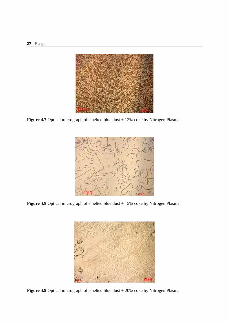
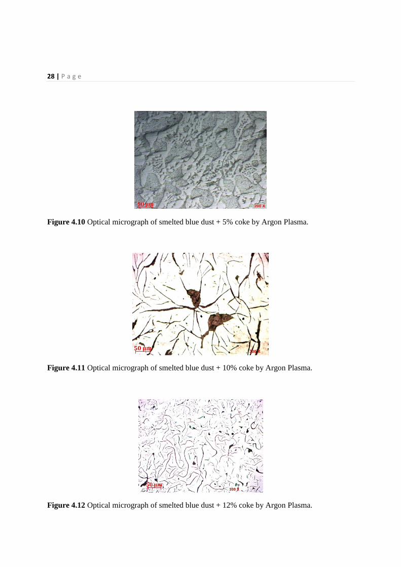
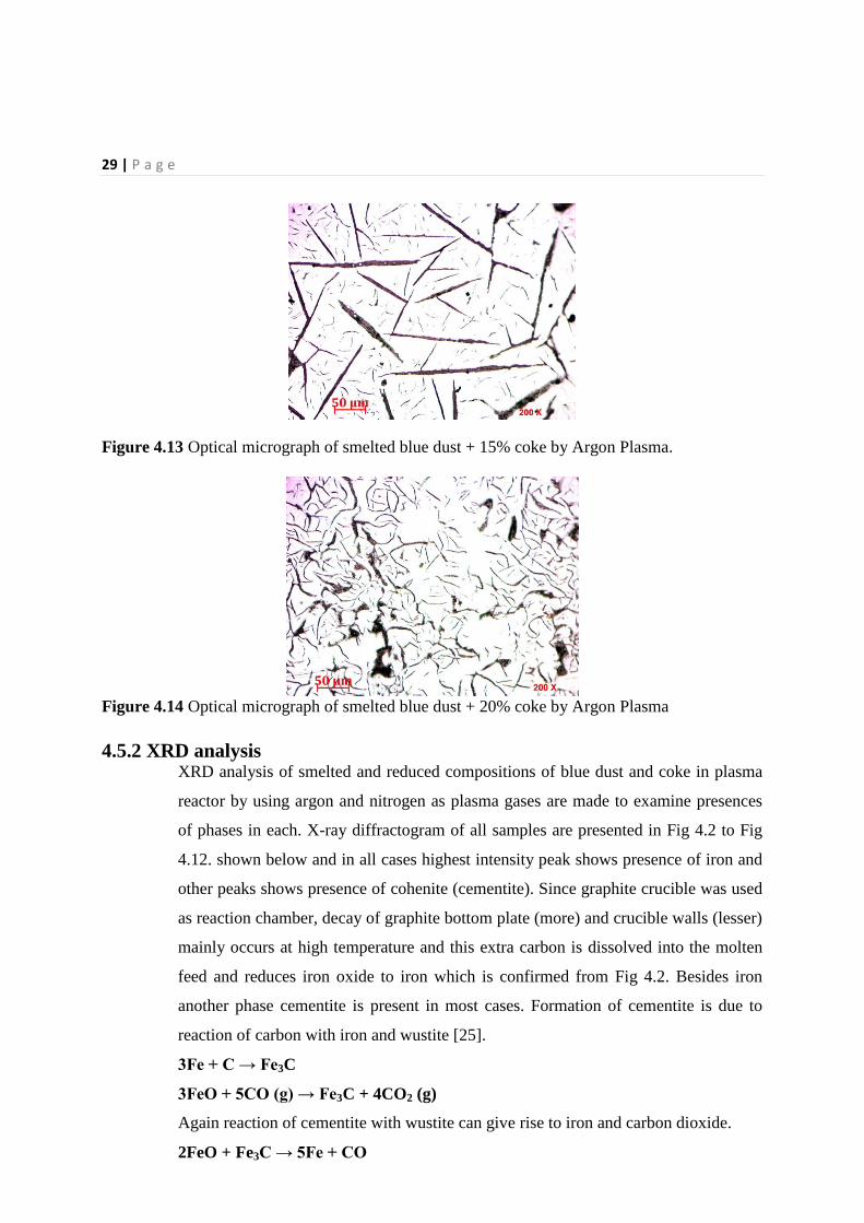
Fractured cementite phases are appeared to be elongated and randomly oriented in ferrite grains,
Fig 4.4- 4.5- and Fig 4.11 . But, finer cementite phases are observed in case of Fig 4.8 and Fig
4.12; whereas in Fig 4.14 fine cementite with some pores is detected. In case of Fig 4.10, a
porous mixture of ferrite and cementite is found. Fig 4.9 shows cementite-pearlite structure. Fig
4.7 coincides with ledeburite structure i.e. a mixture of cementite and pearlite. It may be due to
rapid erosion of graphite from reaction chamber. In Fig 4.6 and Fig 4.13 needle like fractures
along with fine cementite precipitates are revealed.
26 | P a g e
As in case of plasma smelting product is cooled from thousands of degree to room temperature,
formation of cracks is seen in all smelted samples.
Figure 4.4 Optical micrograph of smelted blue dust + 0% coke by Nitrogen Plasma.
Figure 4.5 Optical micrograph of smelted blue dust + 5% coke by Nitrogen Plasma.
Figure 4.6 Optical micrograph of smelted blue dust + 10% coke by Nitrogen Plasma.
27 | P a g e
Figure 4.7 Optical micrograph of smelted blue dust + 12% coke by Nitrogen Plasma.
Figure 4.8 Optical micrograph of smelted blue dust + 15% coke by Nitrogen Plasma.
Figure 4.9 Optical micrograph of smelted blue dust + 20% coke by Nitrogen Plasma.
28 | P a g e
Figure 4.10 Optical micrograph of smelted blue dust + 5% coke by Argon Plasma.
Figure 4.11 Optical micrograph of smelted blue dust + 10% coke by Argon Plasma.
Figure 4.12 Optical micrograph of smelted blue dust + 12% coke by Argon Plasma.
29 | P a g e
Figure 4.13 Optical micrograph of smelted blue dust + 15% coke by Argon Plasma.
Figure 4.14 Optical micrograph of smelted blue dust + 20% coke by Argon Plasma
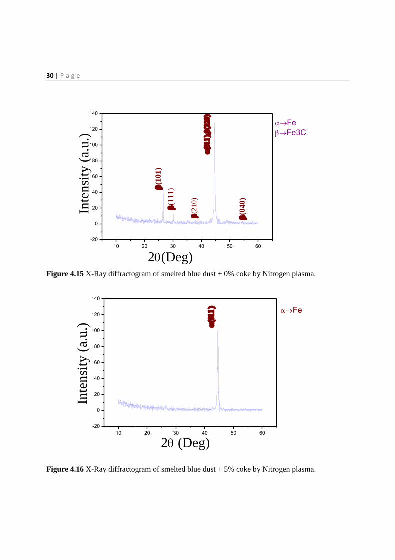
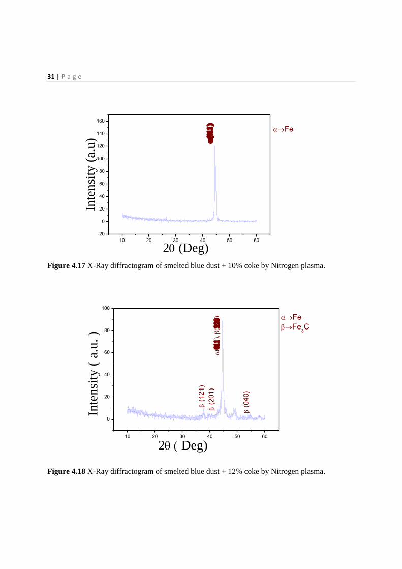
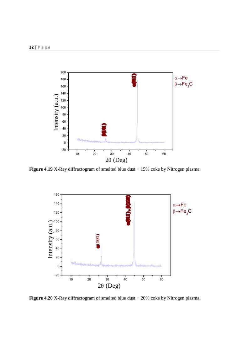
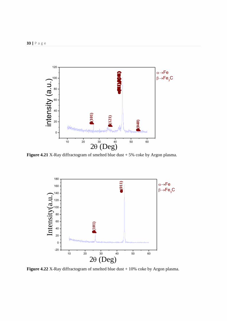
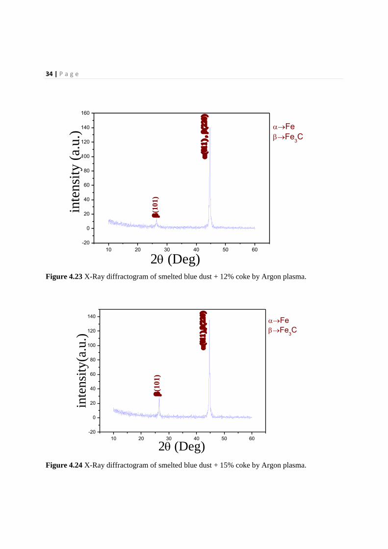
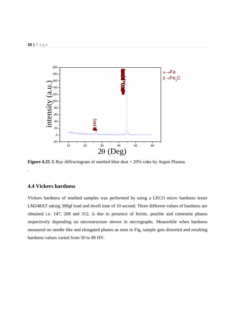
4.5.2 XRD analysis XRD analysis of smelted and reduced compositions of blue dust and coke in plasma
reactor by using argon and nitrogen as plasma gases are made to examine presences
of phases in each. X-ray diffractogram of all samples are presented in Fig 4.2 to Fig
4.12. shown below and in all cases highest intensity peak shows presence of iron and
other peaks shows presence of cohenite (cementite). Since graphite crucible was used
as reaction chamber, decay of graphite bottom plate (more) and crucible walls (lesser)
mainly occurs at high temperature and this extra carbon is dissolved into the molten
feed and reduces iron oxide to iron which is confirmed from Fig 4.2. Besides iron
another phase cementite is present in most cases. Formation of cementite is due to
reaction of carbon with iron and wustite [25].
3Fe + C → Fe3C
3FeO + 5CO (g) → Fe3C + 4CO2 (g)
Again reaction of cementite with wustite can give rise to iron and carbon dioxide.
2FeO + Fe3C → 5Fe + CO
30 | P a g e
10 20 30 40 50 60
-20
0
20
40
60
80
100
120
140
2(Deg)
Inte
nsi
ty (
a.u
.)
(1
01
)
(1
11
)
Fe
Fe3C
(0
40
)
(2
10)
Figure 4.15 X-Ray diffractogram of smelted blue dust + 0% coke by Nitrogen plasma.
10 20 30 40 50 60
-20
0
20
40
60
80
100
120
140
Inte
nsi
ty (
a.u.)
2 (Deg)
Fe
Figure 4.16 X-Ray diffractogram of smelted blue dust + 5% coke by Nitrogen plasma.
31 | P a g e
10 20 30 40 50 60
-20
0
20
40
60
80
100
120
140
160
2 (Deg)
Inte
nsi
ty (
a.u)
Fe
Figure 4.17 X-Ray diffractogram of smelted blue dust + 10% coke by Nitrogen plasma.
10 20 30 40 50 60
0
20
40
60
80
100
Inte
nsi
ty (
a.u
. )
2 Deg)
(
12
1)
(
20
1)
(
04
0)
Fe
Fe3C
Figure 4.18 X-Ray diffractogram of smelted blue dust + 12% coke by Nitrogen plasma.
32 | P a g e
10 20 30 40 50 60
-20
0
20
40
60
80
100
120
140
160
180
200
2 (Deg)
Inte
nsi
ty (
a.u
.)
Fe
Fe3C
Figure 4.19 X-Ray diffractogram of smelted blue dust + 15% coke by Nitrogen plasma.
10 20 30 40 50 60
-20
0
20
40
60
80
100
120
140
160
2 (Deg)
Inte
nsi
ty (
a.u
.)
(1
01
)
Fe
Fe3C
Figure 4.20 X-Ray diffractogram of smelted blue dust + 20% coke by Nitrogen plasma.
33 | P a g e
10 20 30 40 50 60
0
20
40
60
80
100
120
2(Deg)
inte
nsity (
a.u
.)
(1
01
)
(1
21
)
(0
40
)
Fe
Fe3C
Figure 4.21 X-Ray diffractogram of smelted blue dust + 5% coke by Argon plasma.
10 20 30 40 50 60
-20
0
20
40
60
80
100
120
140
160
180
2(Deg)
Inte
nsi
ty(a
.u.)
(1
01
)
(0
11
)
Fe
Fe3C
Figure 4.22 X-Ray diffractogram of smelted blue dust + 10% coke by Argon plasma.
34 | P a g e
10 20 30 40 50 60
-20
0
20
40
60
80
100
120
140
160
2 (Deg)
inte
nsi
ty (
a.u
.)
(1
01)
Fe
Fe3C
Figure 4.23 X-Ray diffractogram of smelted blue dust + 12% coke by Argon plasma.
10 20 30 40 50 60
-20
0
20
40
60
80
100
120
140
2(Deg)
inte
nsi
ty(a
.u.)
(1
01)
Fe
Fe3C
Figure 4.24 X-Ray diffractogram of smelted blue dust + 15% coke by Argon plasma.
35 | P a g e
10 20 30 40 50 60
-20
0
20
40
60
80
100
120
140
160
180
200
2 (Deg)
inte
nsi
ty (
a.u.)
(1
01
)
Fe
Fe3C
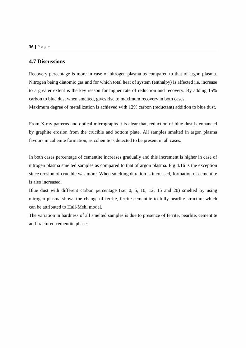
Figure 4.25 X-Ray diffractogram of smelted blue dust + 20% coke by Argon Plasma.
.
4.4 Vickers hardness
Vickers hardness of smelted samples was performed by using a LECO micro hardness tester
LM248AT taking 300gf load and dwell time of 10 second. Three different values of hardness are
obtained i.e. 147, 208 and 312, is due to presence of ferrite, pearlite and cementite phases
respectively depending on microstructure shown in micrographs. Meanwhile when hardness
measured on needle like and elongated phases as seen in Fig, sample gets distorted and resulting
hardness values varied from 50 to 80 HV.
36 | P a g e
4.7 Discussions
Recovery percentage is more in case of nitrogen plasma as compared to that of argon plasma.
Nitrogen being diatomic gas and for which total heat of system (enthalpy) is affected i.e. increase
to a greater extent is the key reason for higher rate of reduction and recovery. By adding 15%
carbon to blue dust when smelted, gives rise to maximum recovery in both cases.
Maximum degree of metallization is achieved with 12% carbon (reductant) addition to blue dust.
From X-ray patterns and optical micrographs it is clear that, reduction of blue dust is enhanced
by graphite erosion from the crucible and bottom plate. All samples smelted in argon plasma
favours in cohenite formation, as cohenite is detected to be present in all cases.
In both cases percentage of cementite increases gradually and this increment is higher in case of
nitrogen plasma smelted samples as compared to that of argon plasma. Fig 4.16 is the exception
since erosion of crucible was more. When smelting duration is increased, formation of cementite
is also increased.
Blue dust with different carbon percentage (i.e. 0, 5, 10, 12, 15 and 20) smelted by using
nitrogen plasma shows the change of ferrite, ferrite-cementite to fully pearlite structure which
can be attributed to Hull-Mehl model.
The variation in hardness of all smelted samples is due to presence of ferrite, pearlite, cementite
and fractured cementite phases.

37 | P a g e
Chapter 5
Conclusions
38 | P a g e
Chapter 5
Conclusions
The conclusions drawn from the present investigation are as follows:
Pig iron can be produced by plasma smelting of blue dust with coke as reductant.
Recovery rate and degree of metallization is affected with carbon addition and type of
plasma forming gas used, i.e. argon and/or nitrogen.
Maximum recovery of 86% is obtained with the sample smelted in nitrogen plasma
with addition of 15% carbon.
Maximum degree of metallization of 98% is achieved for the sample smelted in
nitrogen plasma with 12% carbon addition.
X-ray diffractograms shows the presence of two different phases Fe and Fe3C in case
of all smelting experiments.
Different type of microstructure is observed for samples depending on smelting
parameters considered.
Three different hardness values obtained is corroborated to the presence of ferrite,
pearlite and cementite and fractured cementite phases as observed in microstructure.
SCOPE FOR FUTURE WORK:
The present piece of research work provides choice for future investigators to explore the
possibility of utilization of plasma with increased output by altering more operating
parameters that can produce value added products from wastes with economy.

39 | P a g e
References
40 | P a g e
References
1. S C Mishra, book: Thermal plasma application in metallurgy. ISBN: 9783659235221,
LAMBART Academic Publication, Germany.
2. Vladimir Dembovsky, book: Plasma metallurgy, the principles.
3. M.Mihovsky, review: Thermal plasma application in metallurgy, Journal of the
University of Chemical Technology and Metallurgy, 45, 1, 2010, 3-18.
4. Jerome Feinman, book: Plasma technology in metallurgical processing, ISBN:0-
932897-12-6, printed in U.S.A.
5. A Ghosh, A Chatterjee, Text book of iron making and steelmaking, printed in New
Delhi, 2012.
6. J. Ronald Gonterman, M. A. Weinstein, Plasma Melting Technology and
Applications, 2010.
7. Kouji Mimura1, Michio Nanjo 1
, Production of pure tantalum by carbon-reduction
smelting and hydrogen plasma-arc melting with refining, ISSN: 09161821, April
1990.
8. S. Kouroki1, K.Morita
1, N. Sano
1, Smelting Reduction of Composite Chromite Pellets
by Plasma, Conference name: Proceedings of MINTEK 50: International Conference
on Mineral Science and Technology, 1985.
9. Pravat Kumar Sahoo 1,Ramchandra Krishnarao Galgali 1, Saroj Kumar Singh 1,
Sarama Bhattacharjee 1, Pratima Kumari Mishra 1, Bishnu Charanarbinda Mohanty
1, Preparation of titania-rich slag by plasma smelting of ilmenite, Scandinavian
Journal of Metallurgy, v 28, n 6, p 243-248, December 1999; ISSN:
03710459; Publisher: Munksgaard Int Publ. Ltd.
10. B.B. Nayak 1, B.K. Mishra 1, S. Pradhan 2, Smelting of niobium pentoxide in a
transferred arc argon plasma and characterization of the smelted product, ISSN: 1093-
3611, USA, 2010.
11. R.C. Gupta 1, Research needs for production of Fe-C & Fe-Cr alloys through smelting
reduction process, Conference name: Proceedings of the Workshop on Production of
Liquid Iron Using Coal, Bhubaneswar, India, August 24, 1994 - August 25, 1994.
41 | P a g e
12. Dietmar Vogel 1, Eberhard Steinmetz 1; Herbert Wilhelmi 1, Experiments on the
smelting reduction of oxides of iron, chromium and vanadium and their mixtures with
argon/methane-plasmas, Author affiliation: 1
Industrieofenbau und Waermetechnik,
im Huettenwesen, Germany, ISSN:01774832, 3rd
April 1989.
13. Kyojiro Kaneko, Nobuo Sano, Smelting Reduction For The Direct Production Of
Stainless Steels By Using A Plasma Arc Furnace, Tetsu-To-Hagane/Journal of the
Iron and Steel Institute of Japan, Mar 1983
14. Ivan Imris 1, Alexandra Klenovcanova 1, Matej Imris 2, Thermodynamics of iron
reduction from metallurgical residues, Conference name: Yazawa International
Symposium: Metallurgical and Materials Processing: Principles and Technologies;
Materials Processing Fundamentals and New Technologies, March 2, 2003 - March 6,
2003.
15. Luo, Ting-He; Zeng, Xiao-Ning; Wang, Tie; Luo, Jiang, Direct smelting high alloy
steel and low carbon ferroalloy by plasma smelting reduction, ISSN: 10014985,
march 2002.
16. Horst Mueller, Alfred Weigel, Herbert Wilhelmi, Plasma-smelting Reduction of Iron
Ore, Dec 1983, German.
17. Parth Sarathi Mukherjee 1, Bhagyadhar Bhoi 1, Chitta Ranjan Mishra 2, Ramani
Ranjan Dash 3, Bijaya Kumar Satapathy 2, Kalidas Jayasankar 1, Production of pig
iron from NALCO red mud by application of plasma smelting technology, 1 Institute
of Minerals and Materials Technology, Bhubaneswar 751 013, Orissa, India, 2012.
18. Zheng Guoliang1, Plasma smelting reduction of ilmenite, ISSN: 0449749X , Sep
1986, china.
19. P.V. Ananthapadmanabhana , Patrick R. Taylorb, Wenxian Zhub, Synthesis of
titanium nitride in a thermal plasma reactor, Journal of Alloys and Compounds 287
(1999) 126–129.
20. M. Vijay a, P.V. Ananthapadmanabhan b, K. Ramachandran a, G. Hiremath a, C.B.
Mathai a,B. Nalini c, B.C. Pillai a, Carbothermal reduction of sillimanite in a
transferred arc thermal plasma reactor, Int. Journal of Refractory Metals and Hard
Materials 36 (2013) 174–178.
21. H. R. Larson*, J. F. Elliotit and B. R. Perkins JR, Plasma-arc Smelting of Fine
Chromium Ores, Proceedings oj the 6th
International Ferroalloys COIl8,.es.~, Cape
Town. Volume 1. Johannesburg, SAIMM, 1992. pp. 93-97.
42 | P a g e
22. B.B.Nayak, B.C. Mohanty , K.C Das, preparation of noudular cast iron by plasma
smelting of iron ore fines and ladle addition of zirconia, RRL Bhubaneswar.
23. B.C Mohanty, R.K.Galgali, J.L.Gumaste, U.Syamaprasad, B.B.Nayak, S.K.Singh,
S.C.Mishra, S.Bhattacharjee, P.K.Jena, SG iron production by plasma smelting of
blue dust, RRL Bhubaneswar.
24. Beneficiation of low quality iron ore and its use in DRI production ―an alternative to
Turkish iron ore and steel making industries‖Muammer BILGIC ECOSID Ltd.
25. N.S.Srinivasan and L.-l. Staffansson, Theoretical analysis of the fluidized-bed process
for the reduction of iron ores, Chemical Engineering Science, Vol. 45, No. 5, pp.
1253-1265, 1990.
26. Rodney T. Jones, smelting applications of dc arc furnaces, Mintek, 200 Malibongwe
Drive, Private Bag X3015, Randburg, 2125, South Africa
27. G. K. Bhat, Potential problems and innovations of plasma heat applications in the
metallurgical industry, Vol. 56, No. 2, pp. 209—214, 1984, Printed in Great Britain