Embed Size (px)
DESCRIPTION
Studies on Module 0 HAC. V. Fascianelli , V. Kozhuharov , M. Martini, T. Spadaro, D. Tagnani. Outline. Reminder: HAC insertion in NA62: why/how M odule 0 HAC tests at BTF@LNF, for: obtaining order-zero measurement of light yield assessing possible FEE readout schemes - PowerPoint PPT Presentation
Citation preview

Studies on Module 0 HAC
V. Fascianelli,V. Kozhuharov,
M. Martini,T. Spadaro,D. Tagnani

Photon veto meeting - Liverpool 2
Outline
• Reminder: HAC insertion in NA62: why/how• Module 0 HAC tests at BTF@LNF, for:– obtaining order-zero measurement of light yield– assessing possible FEE readout schemes
• First data/MC comparison studies:– simple digitization/reconstruction algorithms
implemented, following FEE scheme assumed
8/27/13

Photon veto meeting - Liverpool 3
HAC: why, how• From the work by Ruggiero (23/5/2012) and Spasimir
(06/02/2013):– need a new detector to reject O(10) residual background events from K-
>p+p+p- / year– events with p- lost (due to nuclear interaction), and a p+ escaping
detection through the hole, grazing the pipe, emerging at various depths in the range 247 < z < 255 m
– need to efficiently veto p of ~40 GeV, with a detector at z = 253.35 m, while sustaining a muon halo rate of ~4 MHz (dominated by p+ m+ decays downstream GTK3)
– bad energy resolution expected due to lateral leakage– total rate reduced by x10 if E>100 MeV is required– O(<1ns) time resolution to correctly match HAC information with the
rest of event
8/27/13

Photon veto meeting - Liverpool 4
HAC: why, how• A single HAC channel collects light from 6 scintillator tiles (4 mm wide)
alternating to 16-mm Pb layers• Lights from each scintillator collected by a green-centered 1-mm2 WLS fibers • Tentative detector setup: 9 modules, each with 10 channels along the
longitudinal direction
8/27/13
From F. Hahn

Photon veto meeting - Liverpool 5
RO: order of magnitude cost estimate
Consider 90 channels in totalSiPM case:• 100 E/SiPM, 150 E / amplifier + Voltage bias electronics
(evaluation scaling from CHANTI board, 4000 E/32 ch’s): 22500 E
• Digitizer (GANDALF, 12 bit 500 MS/s): 60000 E for 96 channels• Grand total: 82 500 EPMT case:• 400 E/PMT, 200 E/HV-ch: 54000 E• The GANDALF is a common solution for both setups• Grand total is 115 000 E
8/27/13

Photon veto meeting - Liverpool 6
HAC studies
• Order-0 questions: is the scintillator performance still valid and is the light collection enough?
• Order-1 questions: can it be instrumented with SiPM’s or we have to consider PMT’s?
• Order-2 question: can it be readout with Flash ADC’s?
8/27/13

Photon veto meeting - Liverpool 7
Measurement of HAC response ratesOrder-0 questions: are the scintillator performance and the light collection still OK?• Data taken with SiPM at nominal bias voltage• Trigger set at ~30 mV (~7 photoelectrons), rates in dark of ~20 Hz • Use a Cs137, 0.18 MBq, 30.07 years radioactive source• Study trigger rates as the source is moved along the longitudinal direction
8/27/13

Photon veto meeting - Liverpool 8
Measurement of HAC response rates
Order-0 questions: are the scintillator performance and the light collection still OK?• Measurement from each position repeated 4 times• Expect spacing of 4 + 16 mm, OK• 6 peaks spotted, rates span a range of x3... need cosmic-ray characterization, to
be done
8/27/13
no source
Counts from channel 3 / 10 s
Longitudinal Position (cm)

Photon veto meeting - Liverpool 9
BTF runs
• Trigger setup with two positive signals from scintillator paddles
• Electron beam, 50 Hz, O(1) electron multiplicity• Readout via Flash ADC, CAEN module V1751, 8 ch’s, 10 bit, 1
GS/s:– from signal shape, evaluate maximal voltages, integrated charge
around the maximum, event-by-event pedestal, time of the maximum
• HAC runs: 570-MeV beam impact head-on onto channel 0 region at the center
• Expect some lateral leakage due to beam angular dispersion: the HAC is placed ~ 1 m downstream the pipe end
8/27/13

Photon veto meeting - Liverpool 10
BTF runs: e- beam multiplicity, Q’s
8/27/13
Integrated Charge horizontal paddle (C)
Integrated Charge vertical paddle (C)-- 0 electrons-- 1 electron-- 2 electrons-- 3 electrons

Photon veto meeting - Liverpool 11
BTF runs: e- beam multiplicity
Poisson distribution fit: m = 0.94(1), c2 = 1.8/1
8/27/13

Photon veto meeting - Liverpool 12
HAC readout• Interface 6+1 (for calibration) fiber bundle at module end with
3x3 mm2 prototypal high-density SiPM, Hamamatsu MPPC 15 mm x15 mm pixels:– Gain of 2.5 105, at 69.3 V bias at room termperature– 57,600 15 x 15 mm2 pixels in 3x3 mm2 active area– ~ 370 pF capacitance– Gain lower than available SiPM’s by ~x3, but better time resolution
expected, since novel corrections due to delay for far pixels are present (TSV, Through Silicon Via, no wire bonding, see http://kicp-workshops.uchicago.edu/ieu2013/depot/talk-ghassemi-ardavan__1.pdf)
• Voltage supply and amplification during run with electronics tuned for a 70 pF SiPM: time performance not reliable
• Runs were acquired with a PMT readout, as well8/27/13

Photon veto meeting - Liverpool 13
HAC response: sampling a signal
8/27/13
Signal amplitude [mV]
Signal amplitude [mV]
Time [ns]
SiPM readout
PMT readout

Photon veto meeting - Liverpool 14
HAC response: maximal amplitude
8/27/13
Amplitude (mV)
-- 0 electrons-- 1 electron-- 2 electrons-- 3 electrons

Photon veto meeting - Liverpool 15
HAC Response: charge
8/27/13
-- 1 electron-- 2 electrons-- 3 electrons
Integrated charge (C)

Photon veto meeting - Liverpool 16
HAC Response: maximum amplitude
8/27/13
s(V)/V
<V> [mV]
Nominal impact energy (MeV)

Photon veto meeting - Liverpool 17
HAC Response: charge
8/27/13
s(Q)/Q
<Q> [C]
Nominal impact energy (MeV)
s(E)/E ~ 35%/Sqrt(E[GeV])

Photon veto meeting - Liverpool 18
SiPM characterization in dark• SiPM signals sampled in laboratory at fixed temperature and with no input
source• FEE electronics adapted from project developed for Mu2e (Martini, Tagnani,
Corradi) performing accurate APD preamplification• FEE electronics providing x97, while being matched to the SiPM capacitance
– The value correspond to optimal matching and lowest noise• Bias voltage provided via linear power supply• Study of the V-I characteristics
8/27/13
Bias voltage (V)
Current (mA)
Vop

Photon veto meeting - Liverpool 19
SiPM characterization in dark• Apply a 3 mV threshold, corresponding to < 1 pe (see after)• Use oscilloscope as a Flash ADC• Sampling frequency, 1 sample every 0.4 ns
8/27/13
~8 ns rise time
~20 ns fall time
pedestal evaluation region
FADC channel # = T [0.4 ns]

Photon veto meeting - Liverpool 20
SiPM in dark: the analog signal
8/27/13
Vbias = 71.4 V
Amplitude (10 mV / division)
Trigger
Time (10 ns / division)

Photon veto meeting - Liverpool 21
SiPM characterization in dark• Evaluate maximum of SiPM signals and the related population• Fit the first 3 peaks, corresponding to n, n+1, n+2 photoelectrons• Perform a single fit allowing the peak-to-peak distance as free
parameter
8/27/13
Repeat the above steps in a wide range of voltage bias: 69.3 V (nominal + 0.3V) 71.8 V

Photon veto meeting - Liverpool 22
SiPM characterization in dark• Change of the single-photoelectron voltage with the bias, as expected• Single photoelectron ranges from 4.5 mV to 8.5 mV as Vbias varies from
69.3 to 71.8 V
8/27/13
peak to peak distance (V)
bias voltage (V)

Photon veto meeting - Liverpool 23
SiPM characterization in dark• Change of the single-photoelectron voltage with the bias, as expected• Single photoelectron ranges from 4.5 mV to 8.5 mV as Vbias varies from 69.3 to
71.8 V• Result confirmed by the position of the first peak
8/27/13
position of first peak (V)
bias voltage (V)

Photon veto meeting - Liverpool 24
SiPM characterization in dark• Change of the poissonian probability, ranging from ~0.2 to ~0.6 as the bias
voltage varies• Probably an effect linked to PDE variation
8/27/13
bias voltage (V)

Photon veto meeting - Liverpool 25
SiPM characterization in dark• Evaluate charge of SiPM signals and the related population• Fit the first 3 peaks, corresponding to n, n+1, n+2 photoelectrons• Perform a single fit allowing the peak-to-peak distance as free parameter• Repeat the above steps in the bias range: 69.3 V (nominal + 0.3V) 71.8 V
8/27/13Charge (pC)

Photon veto meeting - Liverpool 26
SiPM characterization in dark• Gain evaulation within the expectation: 105 2 105, after correcting for
the FEE amplification of 100 (actually 97)
• Position of 1st peak confirms that the distribution is due to 1, 2, 3 photoelectrons
8/27/13
bias voltage (V)
Gain = 105
Gain = 1.8 105

Photon veto meeting - Liverpool 27
MC HAC Digitization
• Complement the MC made by Spasimir with digitization and reconstruction
• The following assumptions are used:– Scintillator produces 104 photons / MeV– 10-3 of the produced photons reach the SiPM– SiPM PDE = 0.6– The SiPM Gain is 106 (it will be changed in future)– With a FEE electronics amplification of 10, a single
photo-electron produces a 4-mV peak with a 8 ns rise time and a 20 ns fall time
8/27/13

Photon veto meeting - Liverpool 28
HAC MC: energy release
8/27/13
s(E)/E
<E> [MeV]
Electron energy (MeV)
electrons head-on impact

Photon veto meeting - Liverpool 29
HAC MC: electrons MC reconstructed
8/27/13
s(V)/V
<V> [mV]
Electron energy (MeV)
electrons head-on impact
Photon veto meeting - Liverpool 30
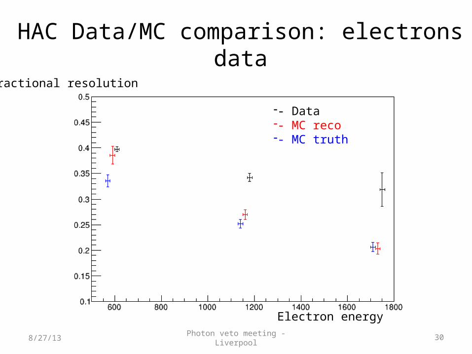
HAC Data/MC comparison: electrons data
8/27/13
-- Data-- MC reco-- MC truth
Fractional resolution
Electron energy

Photon veto meeting - Liverpool 31
Conclusions
8/27/13
Experience with HAC basically shows a working detector:• Satisfactory operation with electron beam at Frascati BTF• SiPM characterization in dark in agreement with Hamamatsu specifications• Benefiting of previous work by Spasimir on MC, a simple procedure for
digitization/reconstruction added (at the moment the code is kept private)• Good linearity of energy response observed• Agreement between data and MC after digitization has to be proved with cosmic rays:
data with 2-3 electrons probably affected by lateral leakageSiPM operation + Flash ADC readout satisfactoryTo-do list:• improved description of MC digitization (pileup of scintillator signals)• Complete development of the low-noise voltage regulator• cosmic ray tests and additional acquisitions with radioactive source• test of final electronics (at the moment, in production)• Channel by channel intercalibration studies• Final design of readout on-board electronics and mechanical interface