Embed Size (px)
Citation preview

RIGHT:
URL:
CITATION:
AUTHOR(S):
ISSUE DATE:
TITLE:
Studies on explosion reaction ofmonovinyl acetylene gas : I.Explosion limits of monovinylacetylene and monovinylacetylene-air mixture
Ikegami, Tatsuya
Ikegami, Tatsuya. Studies on explosion reaction of monovinyl acetylene gas : I. Explosionlimits of monovinyl acetylene and monovinyl acetylene-air mixture.
1963-03-28
http://hdl.handle.net/2433/46823
The Review of Physical Chemistry of Japan Vol. 32 No. 1 & 2 (1962)
STUDIES ON EXPLOSION REACTION OF
MONOVINYL ACETYENE GAS
I. Explosion Limiks of Monovinyl Acetylene and Monovinyl Acetylene-Air Mixture
BY TATSUYA IIC F.GAAtI
(Receimed February 20, 1963)
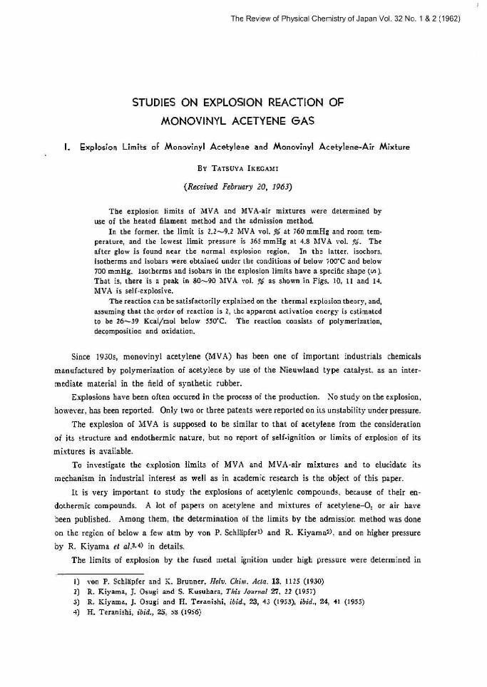
The explosion limits oI MVA and MVA-air mixtures were determined by use of the heated filament method and the admission method.
In the former, the limit is 2.2•--9.2 hfVA voL $~ at i60 mmHg and room tem- perature, and the lon•est limit pressure is 365 mmHg a[ 4.8 ilfVA vol. ,,°b. The after glow is found near the normal explosion region, In Lhe latter. isochors,
isothcrms and isobars were obtained under [he conditions of helow 500'C and below 700 mmHg. Isotherms and isobars in the explosion limits have a specific shape (in ).
That is, there is a peak in 8090 \SVA vol. o as shown in Figs. 10, 11 and 14. MVA is self-explosive.
The reaction can be satisfactorily explained on the thermal explosion theory, and, assuming that Che order of reaction is 2, the apparent activation energy is estimated
to be 26,-39 Kcal/mol below >50'C. The reaction consists of polymerization, decomposition and oxidation.
Since 1930x, monovinyl acetylene (MVA) .has been one of important industriak chemicals
manufactured by polymerization of acetylene by use of the Nieuwlaod type catalyst. as an inter-
mediate material in the field of synthetic rubber.
Explosions have been often occured in the process of the production. No study on the explosion, however, has been reported. Only two or three patents were reported on its unstability under pressure.
The explosion of VIVA is supposed to he similar to that of acetylene from the consideration
of its structure and endothermic nature, but no report of self-ignition or limits of explosion of its
mixtures is. available.
To investigate the explosion limits of MVA and MVA-air mixtures and to elucidate its
mechanism in industrial interest as well as in academic research is the objeU of [his paper.
IC is very important to study the explosions of acetylenic compounds, because of their en-
dothermic compounds. A lot of papers oa acetylene and mixtures of acetylene-Or or atr have
been published. Among them. [he determination of the limits by the admission method was done
on the region of below a few atm by von P. Schlapfert> and R. Kiyamazl, and on higher pressure
by R. Kiyama et al.a•a) in details.
The limits of explosion by the fused metal ignition under high pressure were determined in
1) von P. Schlapfcr and Ii. Brunner, Neiv. China. Acta, 18, 1125 (1930) 2) R. Kiyama, J. Osugi and S. P.usuhara, This Journal 27, 22 (1917)
3) R. Ki}•ama, J. Osugi and H. Teranishi, ibid., 23, 43 (1953), ibid., 24, 41 (t953) 4) H. Teranishi, ibid., 2a"", i8 (1956)
The Review of Physical Chemistry of Japan Vol. 32 No. 1 & 2 (1962)
14 T. Ikegami
details by W. Reppesl. The self-explosion of methyl acetylene under pressure was briefly reported
by F. Fitzgeraldel. No information concerning to the explosion of MVA has been reported.
Various methods7> have been used for the determination of explosion limits. Generally, the
explosion limits are measured by the II. S. Bureau of Mines (U. 5. B. M.) methode> at room
temperature, but it is not suitable for the purpose of elucidating [he reaction mechanism. Fur-
thermore, experimental conditions such as pressure. temperature and so on are restricted The
admission method is better for making mechanism clear.
In ^Part 1" of this paper, the explosion limits at room temperature were determined by use
of the modified U. S. B. M. method in order to be compared with other data. On the other hand,
the admission method was applied [o get more iniormations (that is, induction period, explosion
temperature, products analysis and so on, which are mentioned in "Par[ 2".)
Park i. The Explosion Limits by khe Heated Filament Method
Experimentals
Materials
Monovieyl acetylene (MVA) (CH=C-CH=CH,)
MVA, prepared by polymerization of acetylene with the Nieuwland catalyst, was used. Its purity
was checked by gas chromatographic analysis at every run. Analytical results are given in Table 1.
Table I. Analysis* of MVA (vol. ~ )
Monovinyl_acetylene
Acetylene Acetone
Nitrogen or air
Divinyl acetylene
Others (Vinyl chloride,
rinyl ketane)
acetaldehyde, methyl
99.70-99.94pe
trace
0.04-0.08
0.01-0.20°'
0.00-0.04ro
none
* by gas chromatograph, using DOP (bed) and H: (carrier gas)
I[ was confirmed that the amount of impurities did no[ affect the experimental results.
Apparatus and operation The explosion limits in the available tables have been
generally determined by the U. S. B. M. methodB>. This method has a disadvantage.
It is the Ritagawa`s Laboratory (R. L.) method9> that the above method was simplified and
5) N. Reppe, "Chernie and Technik der Acelylen-Druck-Reaktiad', Velag Chemie, G. m. b. H. (1912) et at.
fi) F. Fitagerald, A'anire, 186, 38G (1960) i) For example, F. $. Dainton, °Chain Reactiott", bfethueo Co., London (1956)
8) H.F. Coward and G.W.Jones,"LimiUOJFI¢mabililyofGarer¢nd Vapors", Bur. Min. Bull., No. 503 (1912) 9) T. Ritagawa and Y. Numano, !. Chem. Soc. Japan, Ind. Clu;m. Sect. (Kogya-Kagaku ZassM); 60,
132 (]957)

The Review of Physical Chemistry of Japan Vol. 32 No. 1 & 2 (1962)
Studies nn Explosion Reaction of Monovinyl Acetylene Gas Is
.- v ~ C st a n Fig. 1 Apparn[us of heated filament metbod.
v A; Reservoir n i "' '° B; Reservoir ~~
C; Mixing bu16
. ~~ n m m -~~ D: Reaction chamber M: Manometer
r N: Safety net P: Pump
modified. In this experiment. the P. L. method, slightly modified on ignition source, was used.
The schematic diagram is shown in Fig. 1.
The combustion chamber (D) was a hard glass tube of about 150 mm in length and 50 mm in
diameter. The upper par[ was covered with a polished glass plate (G) and the lower was closed
by a rubber stopper (R), fitted with a gas lighter on sale (Matsushita Elec. CoJ and a glass cock
(E), as shown in Pig. 2. After evacuating the whole system, the combustible gas-air mixture
v ~*f
P A
1
v~T elYn
~1.~ [~ H /~1
-.ti P
,~
r.
I
aa~,,,
F
II
y-.
R
E
Fig, ] Reaction chamber.
F: Filament
G: Glass plate R: Rubber stopper E: Glass cock
of desired conditions (fixed composition and pressure) was led into the combustion chamber (D).
Ignition was done by closing electric circuit of the gas lighter for constant time (usually, t sec.)
to elevate filament temperature.
In the case of non-ignition, ignition operation was repeated for longer periond (1 sec. and
3 sec.). Ii the gas mixtures were within the explosion limits. explosion would 6laste the glass plate (G,I. In this experiment, another region, in which the after-glow was found around the filament for
a few to some hundreds seconds after the start of ignition and not propagated, was found in
addition to the usual explosion phenomena. So, the period of the after-glow was measured with
a stop watch.
The reproducibility in this method was very good and the error was within ±0.1 vol. 9b in
composition. The smaple gas and unexploded gas rvere examined by gas chromatographic analysis.
The Review of Physical Chemistry of Japan Vol. 32 No. 1 & 2 (1962)
1G T. Ikegami
Results and Considerations
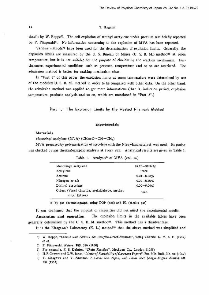
The explosion limits at room temperature (10`C) are shown in Figs. 3 and 4. P mmHg.
denotes the initial pressure of gas mixture. ~ the usual explosion area, and ®the after-glow
area. In [he ~, the induction period was too short to be measured. In the ~B area, a small after-
glow was observed in a few to some hundreds seconds with reducing its intensity, after opening the electric circuit. The periods are indicated with numbers in second in Fig. 4. Though the definite
v mp,xa r laoo mp
900
800 l03 Explmion nrcn
.00
600 -~ 600 500
400 ® Explosion aco .~ $' .,I app .!A.ry ancr elo:e wren .y
~ s inc. 400 ~.:: 100 lu c Ts ,m i,6:
T a ~ j- 0 l0 20 30 4 50 GO i0 90 ~0 ~,nas.rter ela, is n1VA. \bL ' area
u Fig. 3 Isotherm For explosion limit of Il4VA-air
200 s+ mixtures at room temperatur,
i0] xum6er: SaonJ
0 I - 3 4 5 6 n 9 ]0 11 1! nn•,t, va. v
Fig. 4 After-glow area at room temperature.
relations behveen the period of the atter-glow and other factors are no[ found, the following ten-
dencies are recognized, that is, I) the nearer to the © region, the longer the after-glow period is,
and 2) the farther from the boundary, the longer the period is in the ® area.
The phenomena of the after-glow as described above has not been found iu literature. It
seems that there was relation between it and the explosion. There was no pressure change before
and after the after-glow. This means that the reaction is localized around the filament and is
not propagated.
As the results of. Chis experiment. the following explosion limits at iG0 mmHg of [he MVA-air
system were obtained ;
2.2-r9.2 MVA vol. %.
The lowest pressure at the limit was
3G> mmHg at 4.g MVA vol. %
The Review of Physical Chemistry of Japan Vol. 32 No. 1 & 2 (1962)
Studies on Explosion Reaction of illonovinyl Acetylene Gas 17
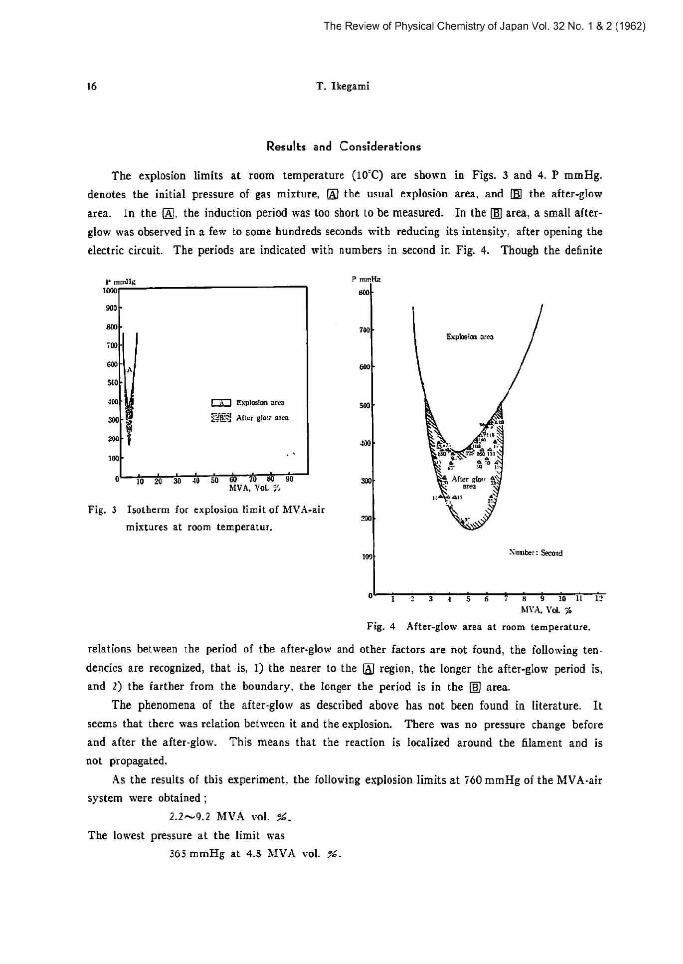
The comparison ofMVA with other gases ar vapors is tried. Though exact comparison is
difficult, because of the lack of the data on the same apparatus, since the results obtained in this
experiment seem to be almost the same as those in the U. S. B. M. and K. L. method, they are
cited in Table 2.
In the table. it is known that MV.A is less dangerous at normal pressure and room tem-
perature in spite of its acetylenic structure.
Table 2 Explosion limits* of some combustible gas-air mixtures
Gas Nol_ formula Mol. wt.Explosion limits (vol. ,4,')
Lower (zr) Upper (xe)
Degree of
danger (H)"*
Acetylene
Ethylene
Propylene
Ethane
Propane
Butane
Hydrogen
C,Ht
CzH.
Calls
C,_Hs
Caf;s
CiHta
Ha
26.0
28.0
42l
30.1
44.1
58.1
2.0
T,5
3.1
2.4
3.0
2,2
1.9
4.0
g0
32
10.3
12.5
9.5
8.5
ii
31.4
9.3
3.3
3.2
3.3
3.5
17.i
hiVA GHa 52.0 2.2 9.2 2.7
s Cited from the below haoklol with exclusion of MVA
Park 2. The Explosion Limits by khe Admission Mekhod
The results in the previous experiment were obtained by local heating in the sample gas at
room temperature The apparatus is restricted in changing experimental conditions such as tem-
perature and pressure, and in analysing reaction products. As it is not suitable to get basic data,
the admission method, which has not a local heating zone, is performed for the fundamental
research in this part.
On various compositions of DIVA and MVA•air mixtures. using reaction tubes of 1030 mm.
in diameter and 120 mm. in length below i00°C and below 600 mmHg, the explosions (flames,
pressure-rising etc.) observed during were a few minutes after admission. The. explosion limits
were determined.
Experimenkals
Materials
,Ylonovinyl acetylene (MVA): the same as in the part 1.
Air: used after filtering and drying as usual
10) B, Lewis and G. von Elve,`Canb+utiort,F2¢merartd Expl¢riorts¢JGoset", 3rd. Ed., Academic Press(196I)
The Review of Physical Chemistry of Japan Vol. 32 No. 1 & 2 (1962)
18 T. Ikegami
Apparatus and operation
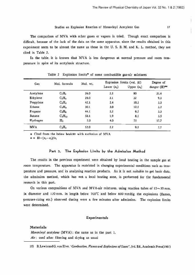
The apparatus used to study is shown schematically in Fig. 5. The gas sample of desired
composion was prepared by the partial pressure method, using a mercury manometer (Mr), and
stored in the resen•oir (ra. 2000 ml.) (S,) over IS hr for completemising. Just before the experi-
ment, the composition was tested and determined by gas chromatographic analysis.
Yart of sample gas in the gas reservoir (S,) was led to the glass bulb (ca. 200 ml.) (S,) at
the fixed pressure by the aid of a Toepler pump (P).
The reaction vessel (V) (~: 10~20mm., 1: 120mm., silica' or hard glass) cuss horimntally
set at the center of [he electric furnace (F) and, after preheated at about 500°C for 30 min. under
vacuum of ca. 10-' mmHg, was kept at the desired temperature for more than 30 min. Immediately
after the sample gas in [he reservoir (S,) was rapidly admitted to [he heated and evacuated
reaction vessel (V), the cork (C,), was closed. The explosion was observed for a few minutes
(over 2 min.). The relation between the pressures admitted in (V) and those of the sample gas in
(S,) was previously obtained by a strainmeter, calibrated by blank test.
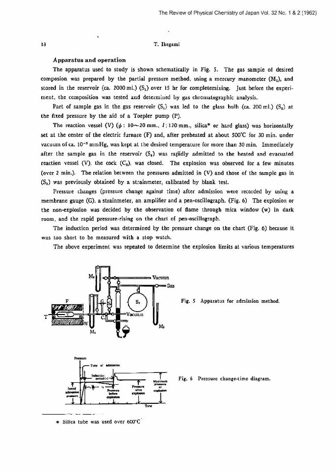
Pressure changes (pressure change against time) after admission were recorded by using a
membrane gauge (G), a strainmeter, an amplifier and open-oscillograph. (Fig. ti) The explosion or
the non-explosion was decided by the observation of (fame through mica window (w) in dark
room, and the rapid pressure-rising on the chart of penoscillograph.
The induction period was determined by the pressure change on the chart (Fig. 6) because it
was too short to be measured with a stop watch.
The above experiment was repeated to determine the explosion limits at carious temperatures
Tf~ Vacuum
Gas
F g, ~ Fig. S Apparatus for admission method. i%
i .1. r, Vacuum
nu
Fi%
i
Vacuum
-Vazuum
8~G
fbllpdp
iW
Ah
G
~_
Tix ,~ rm~~,
~~~~.~~ i
~
~ Silica tube
.. ~-- ̂ ~ ~~ u>:~ Punne °°"2 amr epmo. a~+w~s ~
Time
Fig. 6 Pressure change-time diagram.
u•as used over 600'C

The Review of Physical Chemistry of Japan Vol. 32 No. 1 & 2 (1962)
Studies on Explosion Reaction of Monovinyl Acetylene Gas
(every 5°C in the temperature range of below 700"C), initial pressures (below 700 mmHg) tompositons (O~I00 isIVA vol. ~').
Three kinds of tubes of different diameter (]0 mm, 20 mm, and 30mm.) were used to
ves[iga[e the effects of diameter.
The results obtained were reproduciblein this experiment.
Experimental Resulks
1) Pressure change-time crave Typical curves on the charts of pen-oscillograph
as follows (Fig. 7 (a)~(f)).
Fig. 7 Typical recordings of pressure changedime. P
fi col. °o'. hiVA t'1 I. A. P?_ 460 mmHg
y z a s .~ Y
fel I. A. P.: 330 mmHg a a see
~I~~ L- 33 vol. ,^o', h1VA (c) ~ L R, P.: 460 mmHg
~~t s~_,a__.~_s_~~
P 85 teal. °o. bIVA I. A. P.: 200 mmHg
tm r I,
99,1 vol. %, TSVA
(e) I. R. P.: 600 mmHg
I 3
1'
ltl
Y h
1 a. a
1 2 3 !. 5 6 r
Though the pressure change
to the "normal explosion" among
sion with two stage flame) found
di6erent feature according to th
The cun•e of Fig. 7-(a) whi
pressure increase and decrease drop is observed after rapid pre
the explosion, and the higher c
Though this phenomenon seems
11) M. Suga, This lo+ono7, 29 12) R. Kiyama, J, Osugi and
t3) S. Kusuhara, ibid., 28, 67
19
and
in-
are
_ 99.7 vol. !b, bfVA I. A. P.; 330 mmHg
"` * I . A. P.: Initial admission pressure
-time curves obtained in this experiment are substantially belonged
three L•iads of curves (normal explosion, mild explosion and explo-
by R. Riyamal2>, H. Sugattl and S. Kusuhara131, they have slightly
e composion of gas mixtures.
ch is found below 1~ vol. % of MVA has only one peak and both
are large. Above 15 vol. % of biVA, two stage pressure
ssure rising. That is, the cures have a peak and a plateau during
oncentration of MVA, the more gentle the first pressure drop is.
to be similar to the two stage ignition, the arrangement of peaks
73 (1960) S. Kusuhara, ibid:, 27, 22 (1957) (1959)
i 1

The Review of Physical Chemistry of Japan Vol. 32 No. 1 & 2 (1962)
20 T. Ikegami
is reverse. That is, the highest peak is at the initial part and the pressure decreases in two steps.
Specific flames were not found in this period.
The pressure rising during [be induction Period was nol generally found here, but, inversel}•,.
considerable rapid pressure decreasing e•as recognized at higher concentration of MV~1.
2) Explosion limits r) Isochor cxrvzs The limits in isochors with the use of ~ 20 mm.
tube are shown in Fig. 9 (a)~(c). (Pressure is denoted by the initial admission pressure as in Fig. 6).
u
`s
>b
(U at%
121 sP%
!31 ll%
U1 25Y
~a~
SfVA
erva
MVA
MVa
14
121
12~ f~l
0 10] SO 31 Ml :IO NO .lY ~
P~essme, mmila
>m
E®
P
E F :m
m
[bl
(A/ 25% DIVA
IS) iii MVA
(6) A61P \14'A
m ms nrvA to ns nrvA
w
roi
h5~i4x GFL
sox Lli
o ~m ~ m .m sn rm m. wo
&exurs, mmll¢
m
u
@ mo
s ~=
m
([)
f0) BSX DIVA
(101 %X l/VA
n17 %.7X l1VA
100~GH,
%X C.H.
`~ 1~Ia
Fig. 9 Isochors
vessel)
for explosion limit (~ 20 mm
0 IW YO 7A >D d0 ]O/ t0,
nrewme, mmna
Every curve is smooth, and the explosion peninsula and the cool flame region are not
observed.
No difrerence was recognized between silir and hard glass tube as seen in Fig. S.
P. Schlapfer's resultsl> on C,H„ a•6ich was obtained with a vessel of 15 mm. in diameter
and 70 mm. in length, are added in the Figs. 9 (b) and (c). Even though experimental conditions
are not completely the same, the following conclusions are reasonable:
1) In higher composition, MVA is more stable than C,H„ 2) but it becomes more unstable

T.-mp
Tll
({0
mn
mo
a
Stud ies on Explosion
I6£ \Il'd
SiI4a (:ex0lme root
HaN alao{~tlode
The
Reaction
a Sao :m aoo wo soo sm Pressure. mmHp
educing composition.
Isotherms and isoLars Isotherm
cun~es are summarized in Fig. 11.
aao
. aod['• saa S7vA %~ e
-----~Fxtrapolared Ie ,~ ;pp ------Gll, (s~a'C, p 30mm vesel)
i
~ /r
Review of Physical Chemistry of Japan Vol. 32
of Monovinyl Acetylene Gas
Fig. 9 Isochor
vessel)
for silica and hard glass (~ 20 mm
1No.
21
& 2 (1962)
with reducing
ii) Isotli
Isobar cun~es
`1
.~
A00
3I0
~~
0,o
/~
i,11
~~
asst
J9]C
WA
~ ]0 20
ISOtherm5
(t~ 20 mm
55p~
fiWT
curves
7C a0 50 fiU TD tl0 9D
for explosion limit of MVA
cesseq
are shown in
i
i
i
{
,.,
x
Fig. 10 with that of C,H,
i~~ a
Fig. 11
_~
3)
1
+1
n~
1J),
(11 nOmmH9 (21 120mmH¢ (11 1GO~mnH¢ fa) ?3pmmH¢ (5/ 320mmiie (81 390mmlig (?I JipmmHp ml ssommH¢
ipp
-air
II, 3,
~o zo 3o an a so
Isobars for explosion
(~ 20 mm vessel)
:o All'A
limit
Fig. 10
n on un Cul. ;.
of iSfV:1-aie
14) b1. Suga, Nernories Eh ime Cniv. Sec. 145 (19>9)

The Review of Physical Chemistry of Japan Vol. 32 No. 1 & 2 (1962)
22 T. Ikegami
It is known that t) MVA explodes all over the range of composition, and 2) explosion limits
curve is lowest at about 16% (that is, (MVAJOr)=1) and 3) has a peak in 80~90MVA vol. %.
It should 6e noted that curves show to shape and it changes to L shape with rising tem-
perature as seen in Fig. I I and that MVA is self-esplosive and has a lower limit value (Ad0°C at
560 mmHg) than tbat of Cr H, (575^-620`C at 760 mmHg).
3) Flame color The flame color, which changed from blue, green, yellow and orange
to red with increasing MVA composition, was observed, though definite boundaries between each
color were not obtained (Fig. 12).
a
i ~...,
I~~~ :~
cw.m.
~n....Y Yxb
1 50 W
llYp. Vd M X
TemvT
Fig. 12
r.,~~pc
(a) 99.7% 11VA
Flame color region
Tamm.C
hmpl ~~
ml
(e) 85;L MVA
..o\
~~~ b
Peeume. mmH¢
imcC
awa.+
fd) 3394 MV:1
o im vw
Fiq.13
im sa m +o sm .o mo
Pr<ame. amXv
aa~~
(e) 13iG )iVd
~._
Tevp ~'
yp ~'p YL Im 0 Im 1m xp Prrsme, min Hp
Effect of vessel diameter on
,m~~
v~,~,m.~. mmx.
/9 s2~~ nrvA
.....
.~
.m m w ~m a im m
Pmuvm mmHu
explosion limits of MVA-air
m . m ua mo
IRivun, nnnHx
mixtures
The Review of Physical Chemistry of Japan Vol. 32 No. 1
Studies on Explosion Reaction of ~tonovinyl Acetylene Gas 23
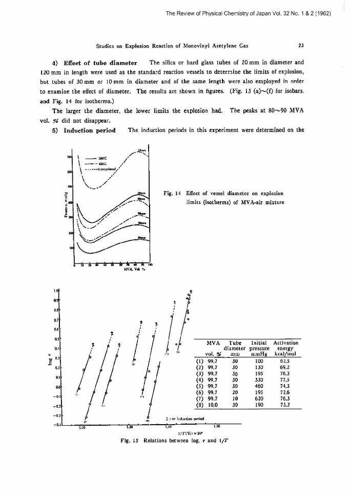
4) Fffeet of tutee diameter The silica or hard glass tubes of 10 mmin diameter and
l20 mm in length were used as the standard reaction vessels to determine the limits of explosion,
but Cubes of 30 mm or 10 mm in diameter and of the same length were also employed in order
to examine the effect of diameter. The results are shown in figures. (Fig. 13 (a)---(f) for isobars,
and Fig. 14 for isotherms.)
The larger the diameter, the lower limits the explosion had. The peals a[ g0^~90 i•SVA
vol. g6 did not disappear.
5) Induction period The induction periods in this experiment were determined on the
ywm
1 / rm - mux
------o-,..mw.e~
\\ / ~;
_ ~~ Fig, 1-0 ESect of vessel diameter on explosion E ~ ~
~ -~•~ Limits (isotherms) of DfVA-air mixture
t /
~ ~ ~' a.,. ~,. '
1 ~, i i' are ~"i ~ /~ %
ad.
i
o ~ . ~w Dn'A Vd ~:
tE 2
as {
ox u 0.r l os {
> ._50
a~
ia:
o.
o.P.
0.0
_ot
_e±
-aa
_ae
0
& 2 (1962)
0
O
~! MVA Tube Initial Activation diameter pressure energy
vol. ?6 mm mmAg kcal/mot
(1) 99.7 (2) 99.7 (3) 99.7 (4) 99.7 (5) 99.7 (6) 99.i (7) 99.7 (g) 10.0
30
30
30
30
30
20
10
30
100
130
195
330
460
195
620
190
62.5
69.2
76,3
77.5
74.3
i 2.6
i 6.3
73.2
. m nd:u~ion rerlaa
tan ~~
Fig.
~:~o
,1TI~K1 x In'
15 Relations betwcen log.
so
r and 1/T

24
Ta61e
The Review of Physical Chemistry of Japan Vol.
T, IF:egami
3 Icduction period
32 No. 1 & 2 (1962)
JiVA com-position
3.1 13.0 30?' 46:d 59% 71?6 199.7 °a
Init. press. 460 mmHg 1460 mmHg 460 mmHg 460 mmHg 460 mmHg 460 mml3g 1460 mmHg
Vessel diameter
20 mm 20 mm 20 mm 20 mm 20 mm 10 mm 20 mm
Temp. 1. P.* Temp. I. P. (Temp.I. P.Temp. I. P. (Temp. I. P. (Temp.I. P. ITemp. I. P.
492°C ti
499C I O.BO403°C h 1400`C ca
410'C 2.25 40i C 0.88
4I5'C rn ~ 425'C ~ ', 425'C'~. ~ 430'C
420'0 115 ~428'CL92 440'C 1.80 1460'C 2.90
~99.7;~ ~99.7?0
460 mmHg 460 mmHg
20 mm 30 m m
Temp, I. P. ITemp. I. P.
453°C m 413'C I ~
X99. i gb ~99.7?0 X99.7 0 ~99.7~ ~99.i a
4fi0 mmHg 330 mmHg l93 mmHg 130 mmHg 100 mmHg
1D mm 30 m m 30 mm 30 mm 30 mm
Temp.l I. P. Temp.1 I. P. ITemp. I. P. ITemp.
493'C 430°C 480'C I w 515'C
I. P. Temp. I, P,
540'C m
460°C 1.07 415'C s.m I soo•c1.04 44SC 5.25 48YC 3.28 szn•C~ zse 545•C z.oo
410°C 4.46
* I. P.: Induction period (sec.)
chart of the recorder as described above. The results obtained are given in Table 3 and Fig. 15.
The definite rules or regularities are not found, but the following general tendencies are
found.
At the lowest explosion temperature:
1) The higher the admission pressure, the longer the induction period is.
2) The wider the tube diameter, the longer the induction period is.
3) T6einduttion period is longer with increasing MVA composition (over 20%) in air.
4) The induction periods are, in general, short. The longest induction period is 10 sec.
The pressure depression during the induction period was seen at the higher ~SVA composition.
Two kinds of the induction periods (r, and rr) were found by $ugat~~l, but, in this experiment, too.
[be induction period (rr), during which pressure did not change, and (-;), during which pressure
decreased, was observed at higher composition of aIVA (Fig. 6). Further investigation of it,
however, was not done.
Consideration
Apparent activation energy of the reaction It [he rate of temperature rising
(wr) in the exothermic reaction were faster than that of cooling (w;), the temperature in that system would be increased and the rate would be also accelerated. From this point of view, if
wr~w;, even in a slow reaction, the reaction temperature would be raised and the reaction
would also be accelerated faster and faster to what we observed as explosion. The lowest initial

The Review of Physical Chemistry of Japan Vol. 32 No.
Studies on Explosion Reaction. of Monovinyl Acetylene Gas 25
temperature is called the explosion (or ignition) temperature (To). N. Semenoff'~.rsa,tst) derived
the following relation with assumption that 1) 6eai transmission was done only through the wall
and 2) any surface reaction did not occur.
log (P/T)=(L•/2RT)+const. (t)
More exactly,
log(P/T t+(2/n))=(a /T)+B (2)
Here. d=0.117 E/n, B=log C/n, C=(NRKS)/(QVkE x 10")
P: Pressure at explosion limit. T: Temperature of reaction vessel (°K)
n : rvfolecurarity or order of reaction E: Activation energy (Kcal/mot)
S : Surface area of vessel k : Rate constant N: Avogadro's number R; Gas constant
s: Heat transfer factor V: Volume of vessel
Q: Heat of reaction Then, n=1, log(P/T')=(A/T)+B (3)
A=0.11 E
SS'hether the explosion reaction of MVA and 14VA-air mixture is based on thermal theory or
the chain theory, what order of reaction it has, and what kind of reaction (polymerization, decomposition
or oxidation) takes the main role, have not been known. The above equations, however, are tested,
assuming that [he thermal theory is better and tte order of reaction is 2 or 1. So, the results
29
1.9
Ltl
1]
!b
1.'a
I,+
1.]
13
t.t
1.0
0.9
ON
W1 davmm ~•eaul
m ~s•~x nrvn
u~ ssz mvn
of asz nrvn
w vx nrvn
~m tsz nrvn
tm sx Mvn
l?I
F)
qi
Q)
IH
(31
~/h
.(q
(fi/
(-0
151
Y
2.0
1.9
Fk
7
fi
3
1.
1.
1.
1?
it
0
9
9
L
D
1
(b) G Amm
m ss.~%
(2) S%
13) Si%
13I 6%
ecssel
nrvA
n1VA
AIVA
nrvA
a] ].U LI L' L3 1. ~5 ~Lr
Fig, l6 Relations between log. P/Te and 1/T
15) N. Semenofi, Z. Pkysik, 46, Si (t928) l6a) N. Semenofi, "C'Irenrica7 Kinetics mrd Chairs Reaclimr' Oxford Univ. 166) N, Semenofi, "Some ProLlems of Ckemical Kinetics mrd Reactivity"
Bradley, Pcrgamon Press Ltd (1959)
a)
(JI
tai
mi
rz,~im
1 & 2 (1962)
Press
Part 1,
1/T('K) x 1U' t3
(1935) translated bl' 1. G. S,
The Review of Physical Chemistry of Japan Vol. 32 No_ 1 & 2 (1962)
16 T. Ikegami
~.a
La
L
a+
ae
av
,.~
~.a
a,
a~
u
of
Cc) ~ ]Omm ~rY•J
~tl
(J
131
Idl
93 iY
Ti%
33M
6Y
,tr~~ t.,
+rva o
1f 1'd :~:
AIyL4 ,~:
(zr(n
~ut (31
r.0 ll 1.' u -~
>a is t/rtm'1 x]a
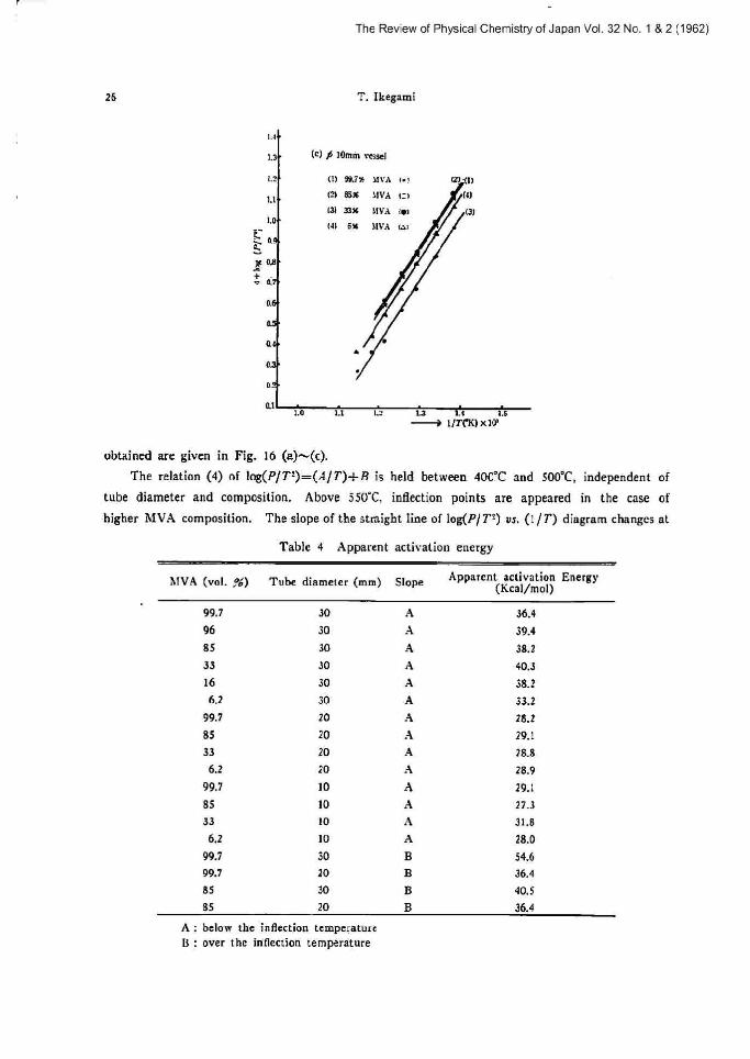
obtained are given in Fig. 16 (a)~(c).
The relation (4) of log(P/T°)=(A/T)-F B is held between 400°C and S00°C, independent of
tube diameter and composition. Above 550°C, inflection points are appeared in the case of
higher MVA composition. The slope of the straight line of ]og(P/T=) vs. (1/T) diagram changes at
Table 4 Apparent activation energy
AfVA Tube diameter (mm) SlopeApparent activation
(Kcal/mal)Energy
99.7
96
85
33
16
6.2
99.7
85
33
6.2
99.7
85
33
6.1
99.7
99.7
85
85
30
30
30
30
30
30
20
20
20
20
10
10
!0
10
30
10
30
20
A
a
a
A
.a
A
A
A
A
A
:1
A
A
B
B
B
B
36.4
39.4
38.2
40.3
38.2
33.2
18.2
29.1
28.8
28.9
29.1
2 i.3
3L8
28.0
54.6
36.4
40.5
36.4
A
13
below the inflection temperature
over the inflection temperature

The Review of Physical Chemistry of Japan Vol. 32 No. 1
Studies on Explosion Reaction of Monovinyl Acetylene Gas 2T
the point and it moves to the higher temperature side with the reduction of [he MVA composition
and tube diameter.
The apparent activation energy is estimated from the slope of the strigh[ line. (Table 4)
The apparent activation energy (E~ is round 29.Kca1/mot below the inflection temperature in
the case of ] 0 mm and 20 mm in diameter. In a tuhe of 30 mm in diameter, E increases to about
39.0 Kcal/mot.
Next, assuming n=1, (that is, ij the reaction was a monomolecular decomposition) equation
(3) was tested and the apparent activation energy was taltulated. The eeamples of MVA are shown in Fig. 17, concerning the log(P/T') vs. (t/T).
The similar results to the above are obtained. Their activation energies are as follows:
(Table 5)
1.9
u
LE
u
~i.~
Su
i.
io
aY
as
oe
,~ ,:r,
Table
~s 1.1 / u~ u ,g
o m.. mxi u
is
os
n
ar
as
u 1: P.'6...IP
tble 5 Apparent
Fig..17 Relation between log. P/T' and I/T
& 2 (1962)
ru
activation energy
Tube diameter (mm) SlopeApparent activation energy
(Kcal/moI)
30
10
A
A
20.3
t 6.8
Now, if the induction period is assumed to 6e the time necessary to produce a definite amount
of the intermediate. the following relationt7.lsb) is given.
; : Induction period. E' : Activation energy
R: Gas constant T: Reaction temperzture
Although some flactuations are found, because of slight inaccuracy of manipulation and apparatus,
almost a linear relation is obtained in the experiment of over 99.7% MVA, concerning log r vs.
(I/T). So, the activation energy estimated is shown in the table of Fig. 15. The values are
17) 6. P. biullins, "Spordaneous Ignition of Ligrcid Fuels" Butternorths Sci. Puh„ London. ([955)
i
i
t
The Review of Physical Chemistry of Japan Vol. 32 No. 1 & 2 (1962)
28 T. Ikegami
fit---7S Kcal/mot and they are higher than the above mentioned.
Reaction mechanism No academic and systematic reports on the reaction mechanism of bfVA and MVA-air mixture have been published. Then. any definite conclusion for the mechanism
could no[ be done, but some consideration for the reaction mechanism wilt be given from phenomena
in this experiment. The explosion reactions of hiVA and MVA-air mixture are concluded to bethermal-explosive
in all range of composition, because the N. N. Semenoff relation as described above can be applied
for this experiment. The inflection of slope, howeveq at higher DfVA composition and temperature
does not indicate that the reaction is simple. The Cact that the activation energy depends upon
the tube diameter suggests that other factors such as the diffusion and complex reaction mechanism
have to be considered.
The nearly equal gradients at [he same diameter and different compositions in Pig. 16 indicate
that the reaction previous to the explosion is also bimolecular, because [he oxidation reaction is
generally bimolecular at dilute concentration of MVA and the above gradients are derived from the same basis of the thermal theory.
The pressure change-time cun•e at higher concentration of 31VA shows pressure depression.
This is considered to be the polimerization reaction.
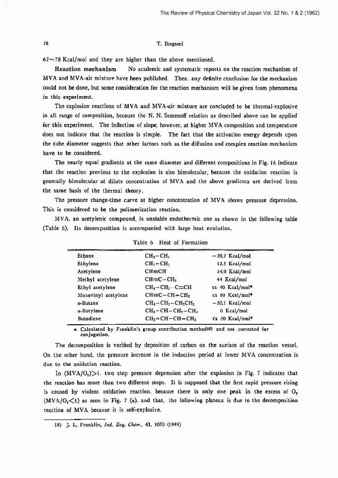
MVA, an acetylenic compound, is unstable endothermic one as shown in the following table
(Table 6). Its decomposition is accompanied with large heat evolution.
Table G Heat of Formation
Ethane
Ethylene
Acetylene
Methyl acetylene
Ethyl acetylene
Monovinyl acetylene
rt-Butane
se-Butylene
butadiene
CHs-CH,
CH:=CH:
CH-CH
CH=C-CHs
CHs-CH:-C-CH
CH=C-CH=CHs
CHa-CH_-CHsCHs
CHs=CH-CHs-CH;,
CHs=CH-CA=CHs
-201 Kcal/mot
t 2.5 Kcal/mot
>4.9 Kcal/mot
44 Rcal/mot
ca 40 Rcal/mol*
ca 69 Kcal/molx -30 ,1 Kcal/mot
0 Rcal/mot
ca 30 Kcal/mole
• Calculated by Franklin's group contribution methadla) and not corrected for conjugation.
The decomposition is verified by deposition of carbon on the surtace of the reaction vessel.
On the other hand, the pressure increase in the induction period at lower MVA concentration is
due to the oxidation reaction.
In (hiVA/0;)~1, two step pressure depression after the esplosion in Fig. 7 indicates that
the reaction has more than two different steps. It is supposed that the first rapid pressure rising is caused by violent oxidation reaction, because there is only one peak in the excess of Os
(MVA/Os~l) as seen in Fig. 7 (a), and that, the following plateau is due to the decomposition reaction of MVA because it is self-explosive.
l8) J. L. Franklin, Ind. Eng. Chtm., 41, 1070 (1949)

The Review of Physical Chemistry of Japan Vol. 32 No. 1 & 2 (1962)
Studies an
It is concluded that the
polymerization, decomposition
Explosion Reaction of
explosion reaction of
and oxidation.
bfooovinyl Acetylene Gas
MVA consists of complex reactions
29
such as
The author wis
and Dr. H. Teranish
[o the Kanegafuchi
sample.
Acknowledgement
hex to thank Professor 1i'. Jbno (Kobe Univ.), Professor J.
i for their kind guidance and advice throughout this work.
Chem. Ind. Co., Ltd. for admittance of this publication
bsugi
He
and
The Kanegafuchi Chem. L+d.
Osaka, !apart
(Kyoto Univ.)
is also grateful
supply of the
Co.. Ltd.