Embed Size (px)
Citation preview
i
A
REPORT ON
―3D Printer‖
(INFORMATIVE REPORT)
2015-16
SUBMITTED BY:
STUDENTS OF FINAL YEAR ELECTRICAL
UNDER THE GUIDANCE OF
Prof. VIVEK TIWARI
Anjuman-I-Islam’s
KALSEKAR TECHNICAL CAMPUS School of Engineering and Technology
New Panvel
ii
A REPORT ON
“3D Printer” (INFORMATIVE REPORT)
2015-16
New panvel
Submitted to: Prof. VIVEK TIWARI
Submitted By: NAME ROLL NO.
SHAIKH MOHAMMED ADIL 14DEE01
ABDUR REHMAN CHHAPRA 13EE13
SHAIKH JUNAID 14DEE15
KHAN NEHAL 14DEE02
Prof. V. TIWARI Prof. S. KALEEM Dr. A. R. HONNUTAGI
(GUIDE) (H.O.D) (DIRECTOR)

iii
ACKNOWLEDGEMENTS
We would like to acknowledge the contributions of those who assisted in the
preparation of this report.
We are particularly grateful for the work done by members of my group. Before we get
into this report we would like to thanks to the members of the group who are a part of this report
and have given their unending contribution from start to end of this report.
We would like to our Prof. VIVEK TIWARI for providing as the required guidance in
process of preparing the report. We would also like to express our deep regards and gratitude to
the director Dr. ABDUL RAZZAK HONNUTAGI.
We would like to express our gratitude towards our parents for their kind co-operation
and encouragement which help us in completion of this project..
We have taken lots of efforts in this project. However, it would not have been possible
without the kind support and help of many individuals and organizations. We would like to extend
our sincere thanks to all of them.

iv
PREFACE
We take the opportunity to present this report ―3D PRINTER”. The object of this report
is to make a 3D printer with low cost.
The report is supported by images to bring out the purpose and message. We have
made sincere attempts and taken every care to present this report in precise and compact
form, the language being as simple as possible.
The task of completion of the project though being difficulty was made quite simple,
interesting and successful due to deep involvement and complete dedication of our group
members.

v
CERTIFICATE
This is to certify that the report entitled ―3D PRINTER‖ submitted by SHAIKH
ADIL , ABDUR REHMAN CHHAPRA , SHAIKH JUNAID , KHAN NEHAL in partial
fulfillment of the requirement for the award of Bachelor of engineering in “ELECTRICAL
ENGINEERING” is an authentic word carried by them under my supervision and guidance.
Date:
Examiner
Prof. V. Tiwari
(Guide)
Prof. S. Kaleem
(HOD)
Dr. Abdul Razzak
Honnutagi
(Director)

vi
ABSTRACT
The inspiration for this project comes from the fact that 3D printer are really innovative
and revolutionary idea but along with that they are very costly, one cannot afford the 3D printer
just for fun or to use at home just to create ideas into reality. This high cost limits the
imagination of the ordinary people. The high quality 3D printers comes at a range of 65000-
140000 rupees.
It all starts with imagination of the object we want to create. One can create a affordable
3D printer by using equipment in their surrounding or probably at home. The technology of 3D
printing can be used to create imagination into reality, parts of the machinery of equipment
which are not available in the market, prototypes of new ideas and most importantly for fun.
Due to the price it's access to world is very limited but through this project there will be
an increase in the access of 3D printers. Obviously this isn't going to be fancy but it will show
the basics of how the 3D printer works. If we can imagine it, we can also create it. The only limit
is our imagination. Want a toy for kids! print it out. Want a container! do it in no time.

vii
DECLARATION
I declare that this written submission represents my ideas in my own words and
where others' ideas or words have been included, I have adequately cited and referenced
the original sources. I also declare that I have adhered to all principles of academic
honesty and integrity and have not misrepresented or fabricated or falsified any
idea/data/fact/source in my submission. I understand that any violation of the above will
be cause for disciplinary action by the Institute and can also evoke penal action from the
sources which have thus not been properly cited or from whom proper permission has not
been taken when needed.
DATE …………………….
PLACE ……………………
(NAME OF THE STUDENT)
SHAIKH ADIL …………………..
ABDUR REHMAN CHHAPRA …………………..
SHAIKH JUNAID …………………..
KHAN NEHAL ………………….
viii
Table of Contents
CHAPTER 1 ...................................................................................................................................... 1
1. Introduction ............................................................................................................................ 1
CHAPTER 2 ...................................................................................................................................... 2
2. History ..................................................................................................................................... 2
CHAPTER 3 ...................................................................................................................................... 6
3. Principle .................................................................................................................................. 6
3.1 Modeling .............................................................................................................................. 6
3.2 Material Jetting ................................................................................................................... 7
3.3 Finishing .............................................................................................................................. 8
3.4 Printing Process .................................................................................................................. 9
3.5 Stereolithography apparatus ........................................................................................... 10
CHAPTER 4 .................................................................................................................................... 12
4. Construction and Working .................................................................................................. 12
4.1 CNC Machine Hardware ................................................................................................. 12
4.1.1 CD ROM .................................................................................................................... 13
4.1.2 Power supply ............................................................................................................. 13
4.1.3 Stepper motor ............................................................................................................ 14
4.1.4 Arduiono uno............................................................................................................. 16
4.1.5 Easy driver................................................................................................................. 16
4.2 Mounting the motor trays ................................................................................................... 17
4.3 Drives And Stepper motor Connections ............................................................................ 19
4.4 CNC Machine Software ....................................................................................................... 19
4.5 3D Printer Hardware ........................................................................................................... 21
4.6 3D Printing Pen .................................................................................................................... 21
4.7 3D Printer Software ............................................................................................................. 24
CHAPTER 5 .................................................................................................................................... 25
5.1 Advantages Of 3D Printer .................................................................................................... 25
5.1.1 Speed .......................................................................................................................... 25
5.1.2 Single Step Manufacture .......................................................................................... 26
5.1.3 Cost ............................................................................................................................. 27
5.1.4 Complexity and design freedom .............................................................................. 27
ix
5.2 Disdvantages Of 3D Printer ................................................................................................. 28
5.2.1 Size ............................................................................................................................. 28
5.2.2 Maintainence ............................................................................................................. 28
5.2.3 Limited Material Operation..................................................................................... 29
5.2.4 Design Challenges ..................................................................................................... 29
CHAPTER 6 .................................................................................................................................... 31
6. Future Scope .......................................................................................................................... 31
6.1 Environment & Improve Sustainability ......................................................................... 32
6.2 3D Printing is Changing: Science, Research, and Education ....................................... 33
6.3 The Enormous Impact That 3D Printing Is Having on General Manufacturing. ...... 33
6.4 Advancing The: Aerospace, Aviation, & Automotive Industries. ................................ 32
6.5 3D Print Your Own Home and Custom Home Décor. .................................................. 34
6.6 3D Printers Are Now Being Used In Culinary Arts and Cooking. .............................. 35
6.7 World's first 3D-printed office building completed in Dubai. ..................................... 35
CHAPTER 7 .................................................................................................................................... 37
7. Applications ........................................................................................................................... 37
CHAPTER 8 .................................................................................................................................... 38
Conclusion .................................................................................................................................... 38
References .................................................................................................................................... 39
x
List of Figures
Fig 1.1 Typical 3D printer ................................................................................................................ 1
Fig 2.1 3D printer in 1980’s .............................................................................................................. 2
Fig 2.2 Charles Hull’s 3D printer .................................................................................................... 3
Fig 2.3 Carbon 3D CLIP technology ............................................................................................... 5
Fig 3.1 CAD model used for 3D printing ........................................................................................ 6
Fig 3.2 Continuous Liquid Interface Production (CLIP) .............................................................. 7
Fig 3.3 Material Jetting .................................................................................................................... 7
Fig 3.4 Complex object Design ......................................................................................................... 8
Fig 3.5 Fused deposition modeling .................................................................................................. 9
Fig 3.6 Object Manufactoring ...................................................................................................... 10
Fig 3.7 3D printed sculpture of the Egyptian Pharaoh ................................................................ 11
Fig 4.1 Materials required .............................................................................................................. 12
Fig 4.2 CD ROM ............................................................................................................................ 13
Fig 4.3 Power Supply ..................................................................................................................... 14
Fig 4.4 Stepper Motor ..................................................................................................................... 15
Fig 4.7 Arduino Uno ....................................................................................................................... 16
Fig 4.8 Easy Driver ........................................................................................................................ 17
Fig 4.9 Required Part of CD ROM ............................................................................................... 18
Fig 4.10 Mechanical assembling of CNC machine ...................................................................... 18
Fig 4.11 Connection of stepper motor and arduino ..................................................................... 19
Fig 4.12 Power Supply connection ................................................................................................. 19
Fig 4.13 Xloader .............................................................................................................................. 20
Fig 4.14 GRBL controller software .............................................................................................. 21
Fig 4.15 3D pen overview................................................................................................................ 23
Fig 4.16 Connections to control forward button .......................................................................... 23
Fig 4.17 Connections to control forward button of 3D pen ........................................................ 24
Fig 5.1 Industrial 3D Printer.......................................................................................................... 25
Fig 5.2 3D Printed object ................................................................................................................ 26
Fig 5.3 Single Step Manufacture .................................................................................................... 26
Fig 5.4 Less Complex ..................................................................................................................... 28
Fig 5.5 Size Drawback .................................................................................................................... 28
Fig 5.6 High Maintainence ........................................................................................................... 29
xi
Fig 5.7 Limited Material Operation ............................................................................................. 29
Fig 5.8 Requires Highly Skilled People ........................................................................................ 30
Fig 6.1 Large 3D Printer ................................................................................................................ 31
Fig 6.2 Environment Sustainability .............................................................................................. 32
Fig 6.3 3D Printing Research ......................................................................................................... 33
Fig 6.4 3D printer Aplication ......................................................................................................... 33
Fig 6.5 Impact On General Manufactoring ................................................................................. 34
Fig 6.6 3D Printed Homes ............................................................................................................. 34
Fig 6.7 3D Printers in Culinary Arts ............................................................................................ 35
Fig 6.8 3D Printed Office in Dubai ................................................................................................ 36
Fig 6.9 Inside 3D printer office ..................................................................................................... 37
1
Chapter 1 Introduction
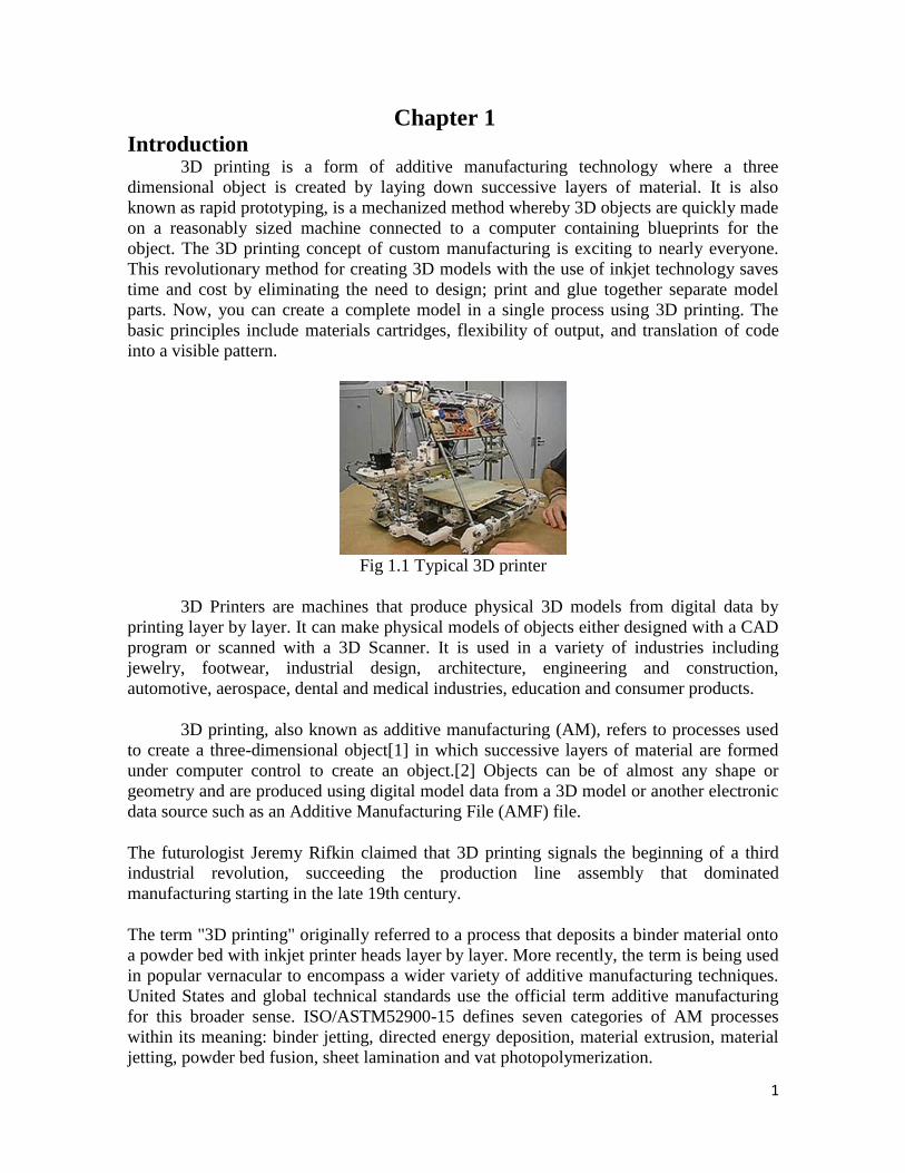
3D printing is a form of additive manufacturing technology where a three
dimensional object is created by laying down successive layers of material. It is also
known as rapid prototyping, is a mechanized method whereby 3D objects are quickly made
on a reasonably sized machine connected to a computer containing blueprints for the
object. The 3D printing concept of custom manufacturing is exciting to nearly everyone.
This revolutionary method for creating 3D models with the use of inkjet technology saves
time and cost by eliminating the need to design; print and glue together separate model
parts. Now, you can create a complete model in a single process using 3D printing. The
basic principles include materials cartridges, flexibility of output, and translation of code
into a visible pattern.
Fig 1.1 Typical 3D printer
3D Printers are machines that produce physical 3D models from digital data by
printing layer by layer. It can make physical models of objects either designed with a CAD
program or scanned with a 3D Scanner. It is used in a variety of industries including
jewelry, footwear, industrial design, architecture, engineering and construction,
automotive, aerospace, dental and medical industries, education and consumer products.
3D printing, also known as additive manufacturing (AM), refers to processes used
to create a three-dimensional object[1] in which successive layers of material are formed
under computer control to create an object.[2] Objects can be of almost any shape or
geometry and are produced using digital model data from a 3D model or another electronic
data source such as an Additive Manufacturing File (AMF) file.
The futurologist Jeremy Rifkin claimed that 3D printing signals the beginning of a third
industrial revolution, succeeding the production line assembly that dominated
manufacturing starting in the late 19th century.
The term "3D printing" originally referred to a process that deposits a binder material onto
a powder bed with inkjet printer heads layer by layer. More recently, the term is being used
in popular vernacular to encompass a wider variety of additive manufacturing techniques.
United States and global technical standards use the official term additive manufacturing
for this broader sense. ISO/ASTM52900-15 defines seven categories of AM processes
within its meaning: binder jetting, directed energy deposition, material extrusion, material
jetting, powder bed fusion, sheet lamination and vat photopolymerization.
2
Chapter 2 History
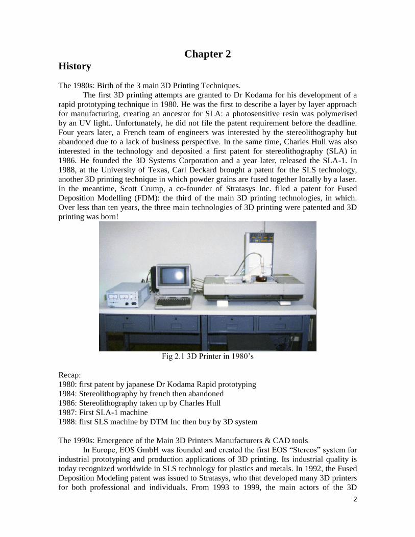
The 1980s: Birth of the 3 main 3D Printing Techniques.
The first 3D printing attempts are granted to Dr Kodama for his development of a
rapid prototyping technique in 1980. He was the first to describe a layer by layer approach
for manufacturing, creating an ancestor for SLA: a photosensitive resin was polymerised
by an UV light.. Unfortunately, he did not file the patent requirement before the deadline.
Four years later, a French team of engineers was interested by the stereolithography but
abandoned due to a lack of business perspective. In the same time, Charles Hull was also
interested in the technology and deposited a first patent for stereolithography (SLA) in
1986. He founded the 3D Systems Corporation and a year later, released the SLA-1. In
1988, at the University of Texas, Carl Deckard brought a patent for the SLS technology,
another 3D printing technique in which powder grains are fused together locally by a laser.
In the meantime, Scott Crump, a co-founder of Stratasys Inc. filed a patent for Fused
Deposition Modelling (FDM): the third of the main 3D printing technologies, in which.
Over less than ten years, the three main technologies of 3D printing were patented and 3D
printing was born!
Fig 2.1 3D Printer in 1980‘s
Recap:
1980: first patent by japanese Dr Kodama Rapid prototyping
1984: Stereolithography by french then abandoned
1986: Stereolithography taken up by Charles Hull
1987: First SLA-1 machine
1988: first SLS machine by DTM Inc then buy by 3D system
The 1990s: Emergence of the Main 3D Printers Manufacturers & CAD tools
In Europe, EOS GmbH was founded and created the first EOS ―Stereos‖ system for
industrial prototyping and production applications of 3D printing. Its industrial quality is
today recognized worldwide in SLS technology for plastics and metals. In 1992, the Fused
Deposition Modeling patent was issued to Stratasys, who that developed many 3D printers
for both professional and individuals. From 1993 to 1999, the main actors of the 3D
3
printing sector emerged with various techniques: ZCorp and binder jetting: Based on
MIT‘s inkjet printing technology, they created the Z402, which produced models using
starch- and plaster‐based powder materials and a water‐based liquid binde Arcam MCP
technology and Selective Laser Melting. At the same time, CAD tools for 3D printing
became more and more available and developed, with for example the creation of Sanders
Prototype (now known as Solidscape), one of the first actors to develop specific tools for
additive manufacturing. The 1990s were also the decade of the first application of 3D
printing by medical researchers, who started to combine medicine and 3D printing, opening
the path to many uses.
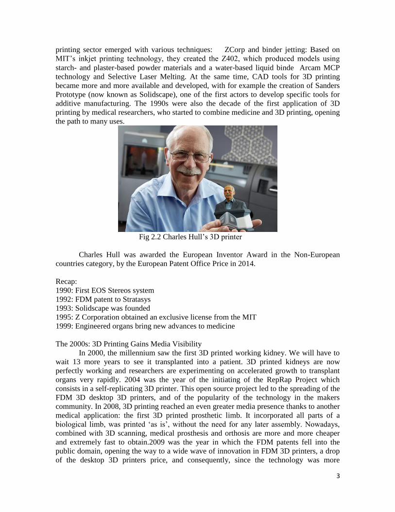
Fig 2.2 Charles Hull‘s 3D printer
Charles Hull was awarded the European Inventor Award in the Non-European
countries category, by the European Patent Office Price in 2014.
Recap:
1990: First EOS Stereos system
1992: FDM patent to Stratasys
1993: Solidscape was founded
1995: Z Corporation obtained an exclusive license from the MIT
1999: Engineered organs bring new advances to medicine
The 2000s: 3D Printing Gains Media Visibility
In 2000, the millennium saw the first 3D printed working kidney. We will have to
wait 13 more years to see it transplanted into a patient. 3D printed kidneys are now
perfectly working and researchers are experimenting on accelerated growth to transplant
organs very rapidly. 2004 was the year of the initiating of the RepRap Project which
consists in a self-replicating 3D printer. This open source project led to the spreading of the
FDM 3D desktop 3D printers, and of the popularity of the technology in the makers
community. In 2008, 3D printing reached an even greater media presence thanks to another
medical application: the first 3D printed prosthetic limb. It incorporated all parts of a
biological limb, was printed ‗as is‘, without the need for any later assembly. Nowadays,
combined with 3D scanning, medical prosthesis and orthosis are more and more cheaper
and extremely fast to obtain.2009 was the year in which the FDM patents fell into the
public domain, opening the way to a wide wave of innovation in FDM 3D printers, a drop
of the desktop 3D printers price, and consequently, since the technology was more
4
accessible, an increased visibility. 2009 was also the year Sculpteo was created, one of the
pioneer of the now flourishing online 3D printing services, another step toward 3D printing
accessibility.
Recap:
2000: a 3D printed working kidney is created
2000: MCP Technologies (an established vacuum casting OEM) introduced the SLM
technology
2005: Z Corp. launched Spectrum Z510. It was the first high-definition color 3D Printer
on the market.
2006: An open source project is initiated (Reprap)
2008: The first 3D printed prosthetic leg
2009: FDM patents in the public domain
2009: Sculpteo is created
The 2010s: Years of Visibility, Innovation and Hopes for 3D Printing
The recent years have been very important for 3D Printing. With the FDM patent
expiration, the first years of the decade have become the years of 3D printing. The desktop
technology invaded the market and made the industrial sector rethink about additive
manufacturing as a reliable production technique. The revolution additive manufacturing
could bring in common consumption was written about extensively, and even though this
total shift of consumption habits hasn‘t happened yet, 3D printing is getting into common
imaginations and practices. In 2013, President Barack Obama mentioned 3D printing as a
major issue for the future in his State of the Union speech, which finished to make ―3D
printing‖ an absolute buzzword. It is now very present in the general public‘s mind, and in
policy makers‘ decisions. The technology is forever progressing, just as are the uses of this
technology. More and more small and big companies take advantage of the low
prototyping price that 3D printing offers, and have fully integrated it in their iteration,
innovation and production processes. In 2010, Urbee was the first 3D printed prototype car.
Its body was fully 3D printed using a very large 3D printer. Now, the 3D printed car is
much more a dream than a reality but in the manufacturing process, many actors are
considering it as a good alternative to traditional methods. In 2011, Cornell University
began to build a 3D food printer. At first sight, it could seem slightly trivial, but NASA is
now researching how astronauts could 3D print food for in space. In 2014, NASA brought
a 3D printer in space to make the first 3D printed object off of the earth. Many medical 3D
printing advances: tissues, organs and low-cost prosthesis. New 3D printers are being
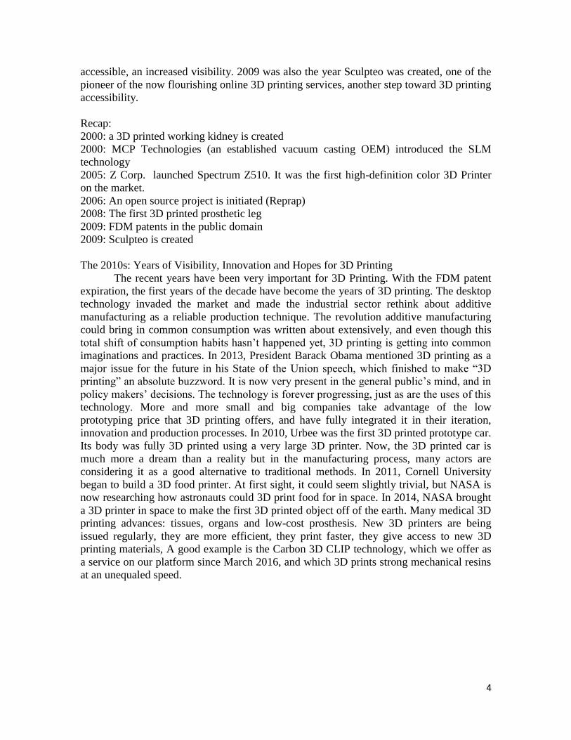
issued regularly, they are more efficient, they print faster, they give access to new 3D
printing materials, A good example is the Carbon 3D CLIP technology, which we offer as
a service on our platform since March 2016, and which 3D prints strong mechanical resins
at an unequaled speed.
5
Fig 2.3 Carbon 3D CLIP technology
New 3D printing materials are being explored every day, from Daniel Kelly‘s lab
who‘s 3D printing bone to the French startup XtreeE, who‘s 3D printing concrete to
revolutionize the construction industry!
At the same time, efforts are constantly made to make 3D printing more accessible,
through education (see our ebook on how to Graduate in 3D printing), shared spaces like
fablabs and makerspaces, and of course 3D printing services like ours: we‘re constantly
adding new materials to our catalogue, new repair and optimisation tools to make sure you
3D print exactly what you had in mind, and new ebooks and tutorials so you master the
technology from design to finish.
Recap:
2010: Urbee is the first 3D printed prototype car presented
2011: Cornell University began to build 3D food printer.
2012: The first prosthetic jaw is printed and implanted
2013: ―3D printing‖ in Obama‘s State of the Union speech
2015: Carbon 3D issues their revolutionary ultra-fast CLIP 3D printing machine
2016: Daniel Kelly‘s lab announces being able to 3D print bone
6
Chapter 3 Principle 3.1 Modeling
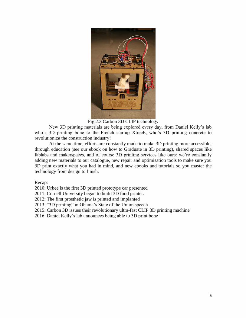
3D printable models may be created with a computer-aided design (CAD) package,
via a 3D scanner, or by a plain digital camera and photogrammetry software. 3D printed
models created with CAD result in reduced errors and can be corrected before printing,
allowing verification in the design of the object before it is printed.
Fig 3.1 CAD model used for 3D printing
Stereolithography (SLA): The most commonly used technology in this processes is
Stereolithography (SLA). This technology employs a vat of liquid ultraviolet curable
photopolymer resin and an ultraviolet laser to build the object‘s layers one at a time. For
each layer, the laser beam traces a cross-section of the part pattern on the surface of the
liquid resin. Exposure to the ultraviolet laser light cures and solidifies the pattern traced on
the resin and joins it to the layer below.
After the pattern has been traced, the SLA‘s elevator platform descends by a
distance equal to the thickness of a single layer, typically 0.05 mm to 0.15 mm (0.002″ to
0.006″). Then, a resin-filled blade sweeps across the cross section of the part, re-coating it
with fresh material. On this new liquid surface, the subsequent layer pattern is traced,
joining the previous layer. The complete three dimensional object is formed by this project.
Stereolithography requires the use of supporting structures which serve to attach the part to
the elevator platform and to hold the object because it floats in the basin filled with liquid
resin. These are removed manually after the object is finished.
This technique was invented in 1986 by Charles Hull, who also at the time founded
the company, 3D Systems.
Digital Light Processing (DLP): DLP or Digital Light Processing refers to a method of
printing that makes use of light and photosensitive polymers. While it is very similar to
stereolithography, the key difference is the light-source. DLP utilises traditional light-
sources like arc lamps.
In most forms of DLP, each layer of the desired structure is projected onto a vat of
liquid resin that is then solidified layer by layer as the buildplate moves up or down. As the
process does each layer successively, it is quicker than most forms of 3D printing.
The Envision Tec Ultra, MiiCraft High Resolution 3D printer, and Lunavast XG2 are
examples of DLP printers. Companies that specialise in DLP technology include ONO and
7
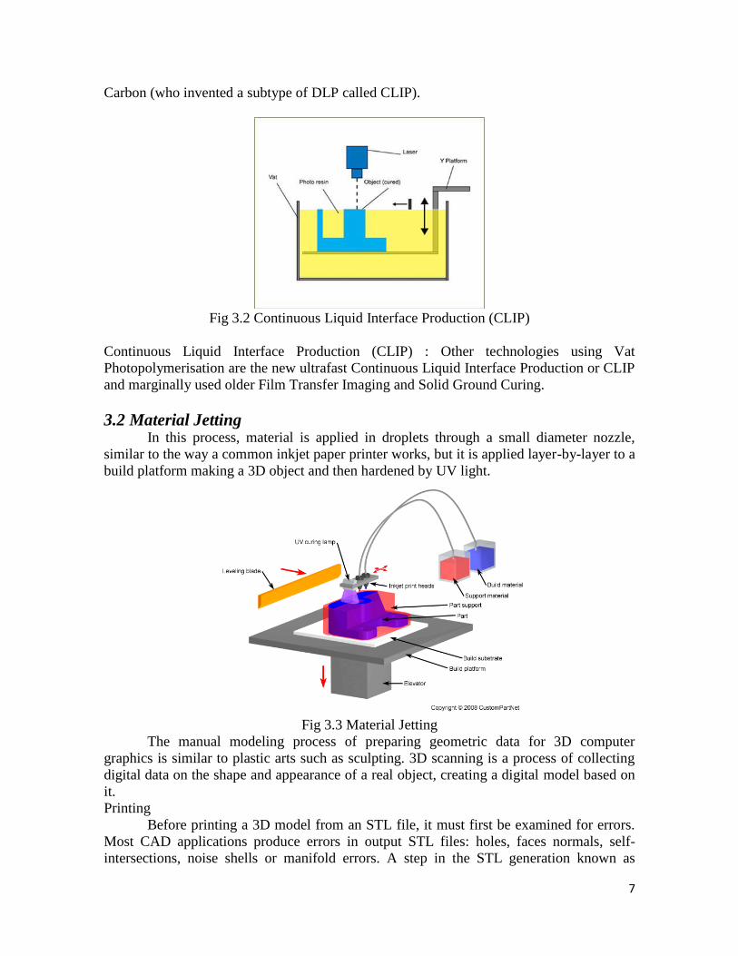
Carbon (who invented a subtype of DLP called CLIP).
Fig 3.2 Continuous Liquid Interface Production (CLIP)
Continuous Liquid Interface Production (CLIP) : Other technologies using Vat
Photopolymerisation are the new ultrafast Continuous Liquid Interface Production or CLIP
and marginally used older Film Transfer Imaging and Solid Ground Curing.
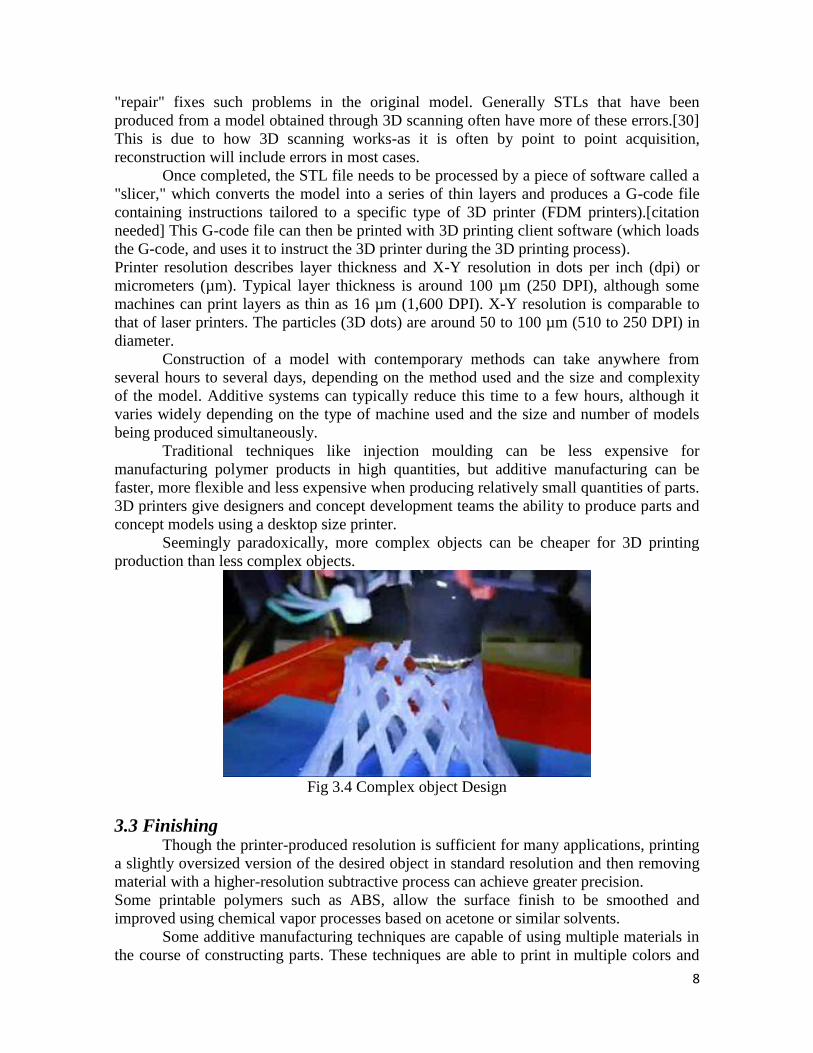
3.2 Material Jetting In this process, material is applied in droplets through a small diameter nozzle,
similar to the way a common inkjet paper printer works, but it is applied layer-by-layer to a
build platform making a 3D object and then hardened by UV light.
Fig 3.3 Material Jetting
The manual modeling process of preparing geometric data for 3D computer
graphics is similar to plastic arts such as sculpting. 3D scanning is a process of collecting
digital data on the shape and appearance of a real object, creating a digital model based on
it.
Printing
Before printing a 3D model from an STL file, it must first be examined for errors.
Most CAD applications produce errors in output STL files: holes, faces normals, self-
intersections, noise shells or manifold errors. A step in the STL generation known as
8
"repair" fixes such problems in the original model. Generally STLs that have been
produced from a model obtained through 3D scanning often have more of these errors.[30]
This is due to how 3D scanning works-as it is often by point to point acquisition,
reconstruction will include errors in most cases.
Once completed, the STL file needs to be processed by a piece of software called a
"slicer," which converts the model into a series of thin layers and produces a G-code file
containing instructions tailored to a specific type of 3D printer (FDM printers).[citation
needed] This G-code file can then be printed with 3D printing client software (which loads
the G-code, and uses it to instruct the 3D printer during the 3D printing process).
Printer resolution describes layer thickness and X-Y resolution in dots per inch (dpi) or
micrometers (µm). Typical layer thickness is around 100 µm (250 DPI), although some
machines can print layers as thin as 16 µm (1,600 DPI). X-Y resolution is comparable to
that of laser printers. The particles (3D dots) are around 50 to 100 µm (510 to 250 DPI) in
diameter.
Construction of a model with contemporary methods can take anywhere from
several hours to several days, depending on the method used and the size and complexity
of the model. Additive systems can typically reduce this time to a few hours, although it
varies widely depending on the type of machine used and the size and number of models
being produced simultaneously.
Traditional techniques like injection moulding can be less expensive for
manufacturing polymer products in high quantities, but additive manufacturing can be
faster, more flexible and less expensive when producing relatively small quantities of parts.
3D printers give designers and concept development teams the ability to produce parts and
concept models using a desktop size printer.
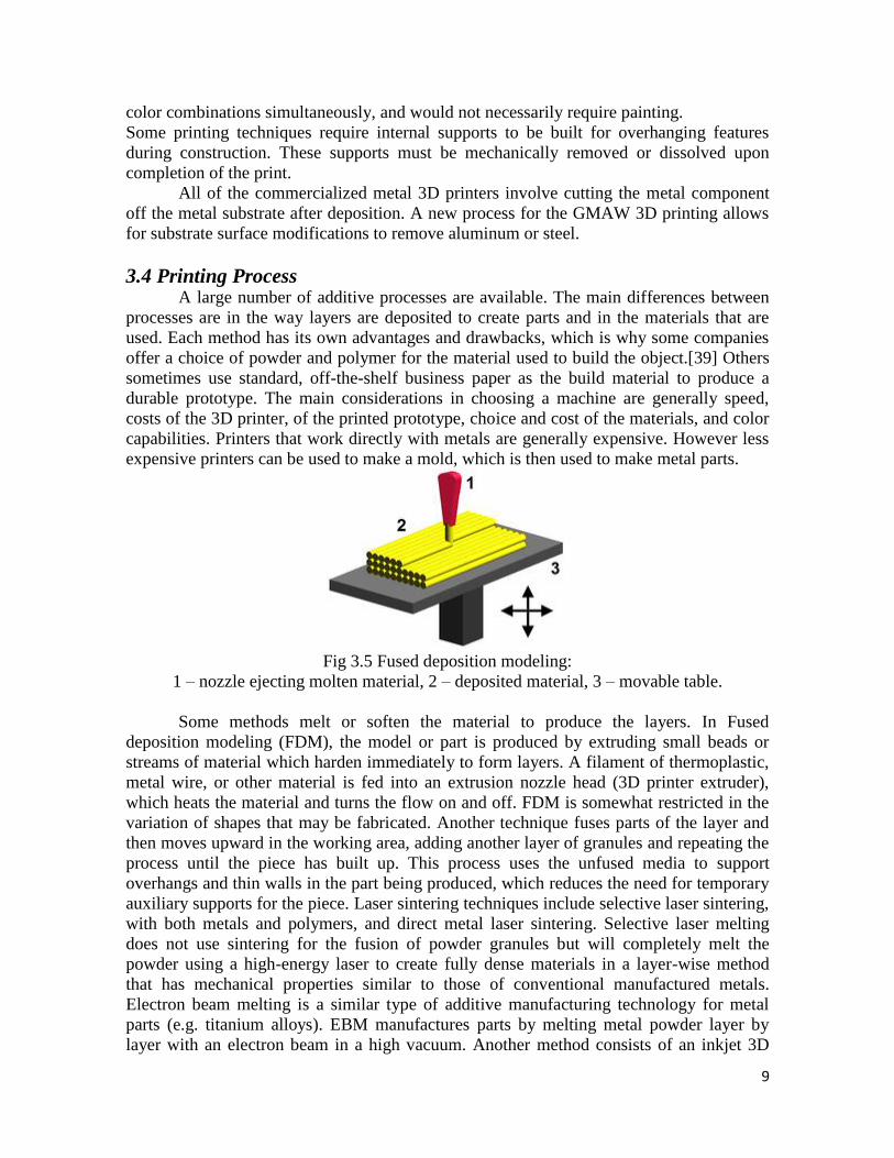
Seemingly paradoxically, more complex objects can be cheaper for 3D printing
production than less complex objects.
Fig 3.4 Complex object Design
3.3 Finishing Though the printer-produced resolution is sufficient for many applications, printing
a slightly oversized version of the desired object in standard resolution and then removing
material with a higher-resolution subtractive process can achieve greater precision.
Some printable polymers such as ABS, allow the surface finish to be smoothed and
improved using chemical vapor processes based on acetone or similar solvents.
Some additive manufacturing techniques are capable of using multiple materials in
the course of constructing parts. These techniques are able to print in multiple colors and
9
color combinations simultaneously, and would not necessarily require painting.
Some printing techniques require internal supports to be built for overhanging features
during construction. These supports must be mechanically removed or dissolved upon
completion of the print.
All of the commercialized metal 3D printers involve cutting the metal component
off the metal substrate after deposition. A new process for the GMAW 3D printing allows
for substrate surface modifications to remove aluminum or steel.
3.4 Printing Process A large number of additive processes are available. The main differences between
processes are in the way layers are deposited to create parts and in the materials that are
used. Each method has its own advantages and drawbacks, which is why some companies
offer a choice of powder and polymer for the material used to build the object.[39] Others
sometimes use standard, off-the-shelf business paper as the build material to produce a
durable prototype. The main considerations in choosing a machine are generally speed,
costs of the 3D printer, of the printed prototype, choice and cost of the materials, and color
capabilities. Printers that work directly with metals are generally expensive. However less
expensive printers can be used to make a mold, which is then used to make metal parts.
Fig 3.5 Fused deposition modeling:
1 – nozzle ejecting molten material, 2 – deposited material, 3 – movable table.
Some methods melt or soften the material to produce the layers. In Fused
deposition modeling (FDM), the model or part is produced by extruding small beads or
streams of material which harden immediately to form layers. A filament of thermoplastic,
metal wire, or other material is fed into an extrusion nozzle head (3D printer extruder),
which heats the material and turns the flow on and off. FDM is somewhat restricted in the
variation of shapes that may be fabricated. Another technique fuses parts of the layer and
then moves upward in the working area, adding another layer of granules and repeating the
process until the piece has built up. This process uses the unfused media to support
overhangs and thin walls in the part being produced, which reduces the need for temporary
auxiliary supports for the piece. Laser sintering techniques include selective laser sintering,
with both metals and polymers, and direct metal laser sintering. Selective laser melting
does not use sintering for the fusion of powder granules but will completely melt the
powder using a high-energy laser to create fully dense materials in a layer-wise method
that has mechanical properties similar to those of conventional manufactured metals.
Electron beam melting is a similar type of additive manufacturing technology for metal
parts (e.g. titanium alloys). EBM manufactures parts by melting metal powder layer by
layer with an electron beam in a high vacuum. Another method consists of an inkjet 3D
10
printing system, which creates the model one layer at a time by spreading a layer of
powder (plaster, or resins) and printing a binder in the cross-section of the part using an
inkjet-like process. With laminated object manufacturing, thin layers are cut to shape and
joined together.
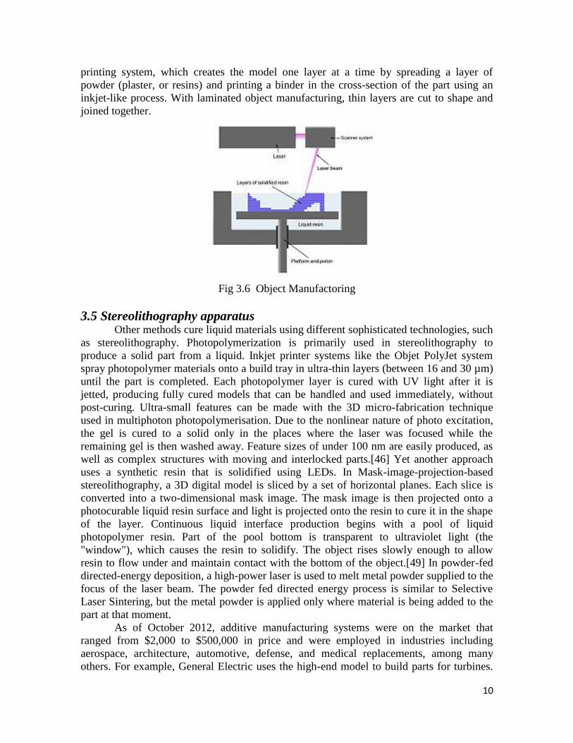
Fig 3.6 Object Manufactoring
3.5 Stereolithography apparatus Other methods cure liquid materials using different sophisticated technologies, such
as stereolithography. Photopolymerization is primarily used in stereolithography to
produce a solid part from a liquid. Inkjet printer systems like the Objet PolyJet system
spray photopolymer materials onto a build tray in ultra-thin layers (between 16 and 30 µm)
until the part is completed. Each photopolymer layer is cured with UV light after it is
jetted, producing fully cured models that can be handled and used immediately, without
post-curing. Ultra-small features can be made with the 3D micro-fabrication technique
used in multiphoton photopolymerisation. Due to the nonlinear nature of photo excitation,
the gel is cured to a solid only in the places where the laser was focused while the
remaining gel is then washed away. Feature sizes of under 100 nm are easily produced, as
well as complex structures with moving and interlocked parts.[46] Yet another approach
uses a synthetic resin that is solidified using LEDs. In Mask-image-projection-based
stereolithography, a 3D digital model is sliced by a set of horizontal planes. Each slice is
converted into a two-dimensional mask image. The mask image is then projected onto a
photocurable liquid resin surface and light is projected onto the resin to cure it in the shape
of the layer. Continuous liquid interface production begins with a pool of liquid
photopolymer resin. Part of the pool bottom is transparent to ultraviolet light (the
"window"), which causes the resin to solidify. The object rises slowly enough to allow
resin to flow under and maintain contact with the bottom of the object.[49] In powder-fed
directed-energy deposition, a high-power laser is used to melt metal powder supplied to the
focus of the laser beam. The powder fed directed energy process is similar to Selective
Laser Sintering, but the metal powder is applied only where material is being added to the
part at that moment.
As of October 2012, additive manufacturing systems were on the market that
ranged from $2,000 to $500,000 in price and were employed in industries including
aerospace, architecture, automotive, defense, and medical replacements, among many
others. For example, General Electric uses the high-end model to build parts for turbines.
11
Many of these systems are used for rapid prototyping, before mass production methods are
employed. Higher education has proven to be a major buyer of desktop and professional
3D printers which industry experts generally view as a positive indicator.[53] Libraries
around the world have also become locations to house smaller 3D printers for educational
and community access.[54] Several projects and companies are making efforts to develop
affordable 3D printers for home desktop use. Much of this work has been driven by and
targeted at DIY/Maker/enthusiast/early adopter communities, with additional ties to the
academic and hacker communities.
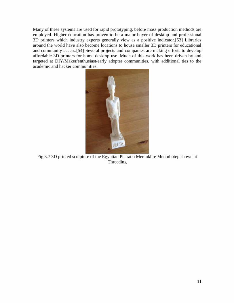
Fig 3.7 3D printed sculpture of the Egyptian Pharaoh Merankhre Mentuhotep shown at
Threeding
12
Chapter 4 Construction And Working 4.1 CNC Machine Hardware
The 3D printers basically depend on the construction and principle of CNC machine.
Most of the 3D printers are expensive, but there are some recent trends in 3D printer which
causes reduction in the price of 3D printer. Mostly 3D printer are use for more in hobbies
rather than industrial application. Companies have also realized the potential of a consumer
market for 3D printers and as such have been aggressively courting enthusiasts with
cheaper and better models.
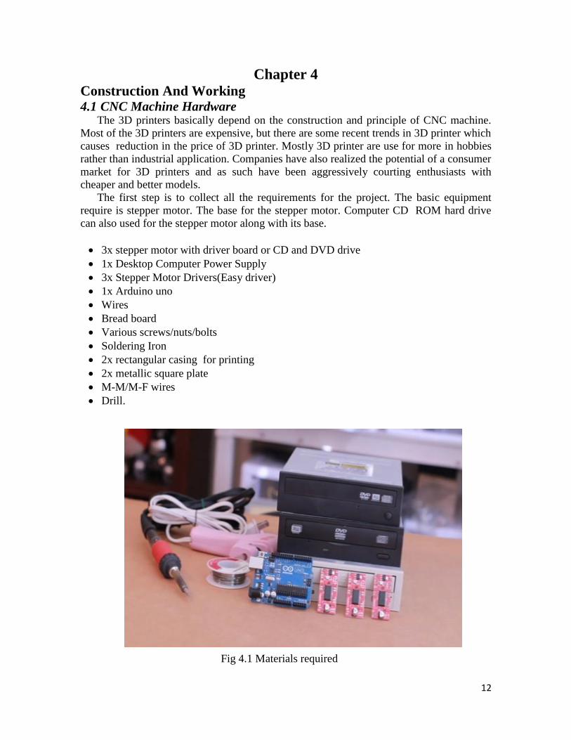
The first step is to collect all the requirements for the project. The basic equipment
require is stepper motor. The base for the stepper motor. Computer CD ROM hard drive
can also used for the stepper motor along with its base.
3x stepper motor with driver board or CD and DVD drive
1x Desktop Computer Power Supply
3x Stepper Motor Drivers(Easy driver)
1x Arduino uno
Wires
Bread board
Various screws/nuts/bolts
Soldering Iron
2x rectangular casing for printing
2x metallic square plate
M-M/M-F wires
Drill.
Fig 4.1 Materials required
13
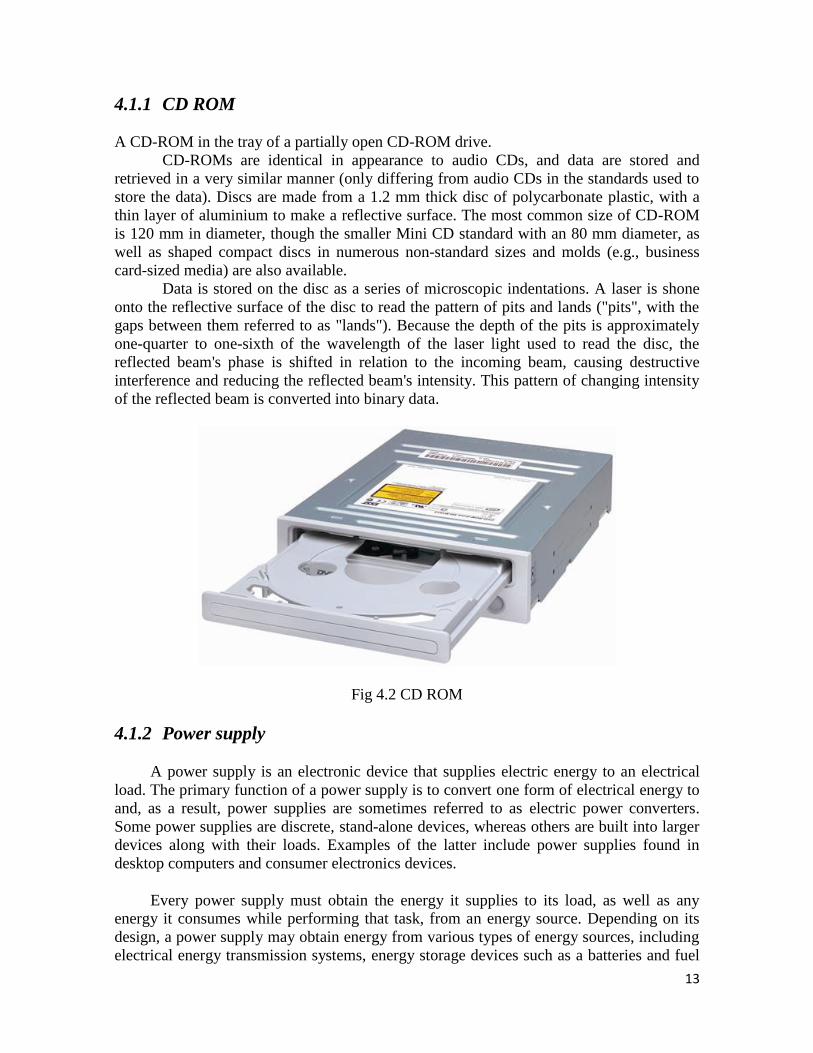
4.1.1 CD ROM
A CD-ROM in the tray of a partially open CD-ROM drive.
CD-ROMs are identical in appearance to audio CDs, and data are stored and
retrieved in a very similar manner (only differing from audio CDs in the standards used to
store the data). Discs are made from a 1.2 mm thick disc of polycarbonate plastic, with a
thin layer of aluminium to make a reflective surface. The most common size of CD-ROM
is 120 mm in diameter, though the smaller Mini CD standard with an 80 mm diameter, as
well as shaped compact discs in numerous non-standard sizes and molds (e.g., business
card-sized media) are also available.
Data is stored on the disc as a series of microscopic indentations. A laser is shone
onto the reflective surface of the disc to read the pattern of pits and lands ("pits", with the
gaps between them referred to as "lands"). Because the depth of the pits is approximately
one-quarter to one-sixth of the wavelength of the laser light used to read the disc, the
reflected beam's phase is shifted in relation to the incoming beam, causing destructive
interference and reducing the reflected beam's intensity. This pattern of changing intensity
of the reflected beam is converted into binary data.
Fig 4.2 CD ROM
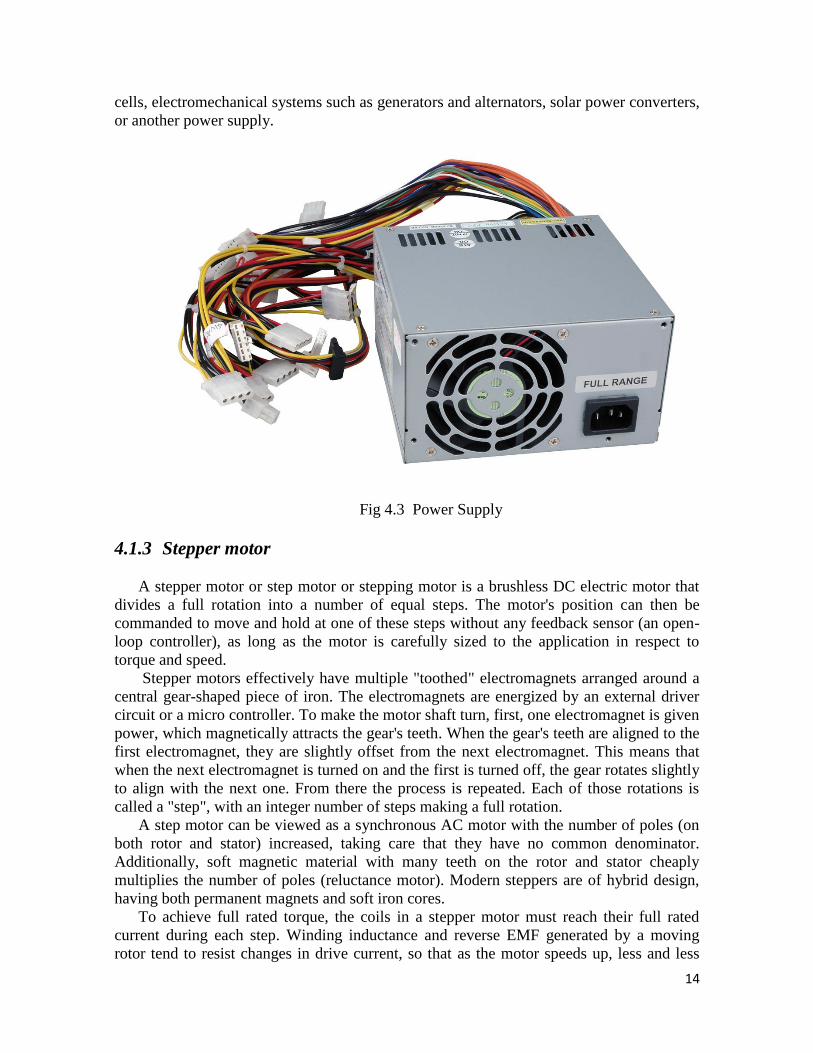
4.1.2 Power supply
A power supply is an electronic device that supplies electric energy to an electrical
load. The primary function of a power supply is to convert one form of electrical energy to
and, as a result, power supplies are sometimes referred to as electric power converters.
Some power supplies are discrete, stand-alone devices, whereas others are built into larger
devices along with their loads. Examples of the latter include power supplies found in
desktop computers and consumer electronics devices.
Every power supply must obtain the energy it supplies to its load, as well as any
energy it consumes while performing that task, from an energy source. Depending on its
design, a power supply may obtain energy from various types of energy sources, including
electrical energy transmission systems, energy storage devices such as a batteries and fuel
14
cells, electromechanical systems such as generators and alternators, solar power converters,
or another power supply.
Fig 4.3 Power Supply
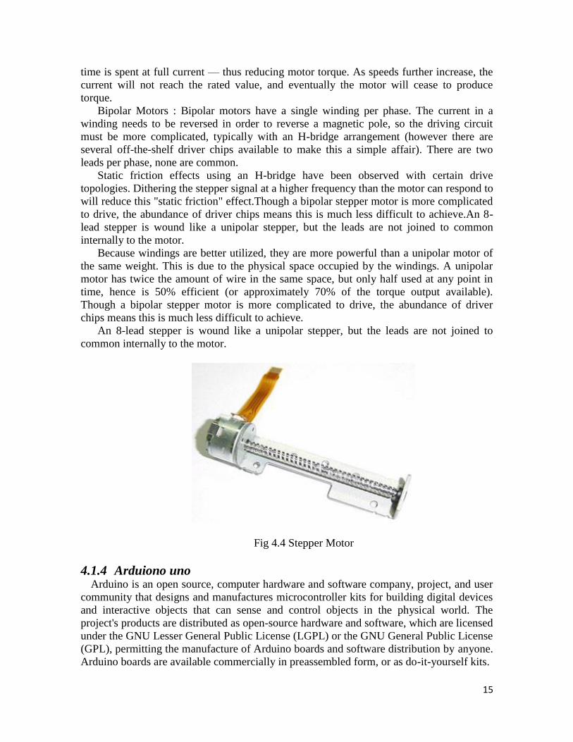
4.1.3 Stepper motor
A stepper motor or step motor or stepping motor is a brushless DC electric motor that
divides a full rotation into a number of equal steps. The motor's position can then be
commanded to move and hold at one of these steps without any feedback sensor (an open-
loop controller), as long as the motor is carefully sized to the application in respect to
torque and speed.
Stepper motors effectively have multiple "toothed" electromagnets arranged around a
central gear-shaped piece of iron. The electromagnets are energized by an external driver
circuit or a micro controller. To make the motor shaft turn, first, one electromagnet is given
power, which magnetically attracts the gear's teeth. When the gear's teeth are aligned to the
first electromagnet, they are slightly offset from the next electromagnet. This means that
when the next electromagnet is turned on and the first is turned off, the gear rotates slightly
to align with the next one. From there the process is repeated. Each of those rotations is
called a "step", with an integer number of steps making a full rotation.
A step motor can be viewed as a synchronous AC motor with the number of poles (on
both rotor and stator) increased, taking care that they have no common denominator.
Additionally, soft magnetic material with many teeth on the rotor and stator cheaply
multiplies the number of poles (reluctance motor). Modern steppers are of hybrid design,
having both permanent magnets and soft iron cores.
To achieve full rated torque, the coils in a stepper motor must reach their full rated
current during each step. Winding inductance and reverse EMF generated by a moving
rotor tend to resist changes in drive current, so that as the motor speeds up, less and less
15
time is spent at full current — thus reducing motor torque. As speeds further increase, the
current will not reach the rated value, and eventually the motor will cease to produce
torque.
Bipolar Motors : Bipolar motors have a single winding per phase. The current in a
winding needs to be reversed in order to reverse a magnetic pole, so the driving circuit
must be more complicated, typically with an H-bridge arrangement (however there are
several off-the-shelf driver chips available to make this a simple affair). There are two
leads per phase, none are common.
Static friction effects using an H-bridge have been observed with certain drive
topologies. Dithering the stepper signal at a higher frequency than the motor can respond to
will reduce this "static friction" effect.Though a bipolar stepper motor is more complicated
to drive, the abundance of driver chips means this is much less difficult to achieve.An 8-
lead stepper is wound like a unipolar stepper, but the leads are not joined to common
internally to the motor.
Because windings are better utilized, they are more powerful than a unipolar motor of
the same weight. This is due to the physical space occupied by the windings. A unipolar
motor has twice the amount of wire in the same space, but only half used at any point in
time, hence is 50% efficient (or approximately 70% of the torque output available).
Though a bipolar stepper motor is more complicated to drive, the abundance of driver
chips means this is much less difficult to achieve.
An 8-lead stepper is wound like a unipolar stepper, but the leads are not joined to
common internally to the motor.
Fig 4.4 Stepper Motor
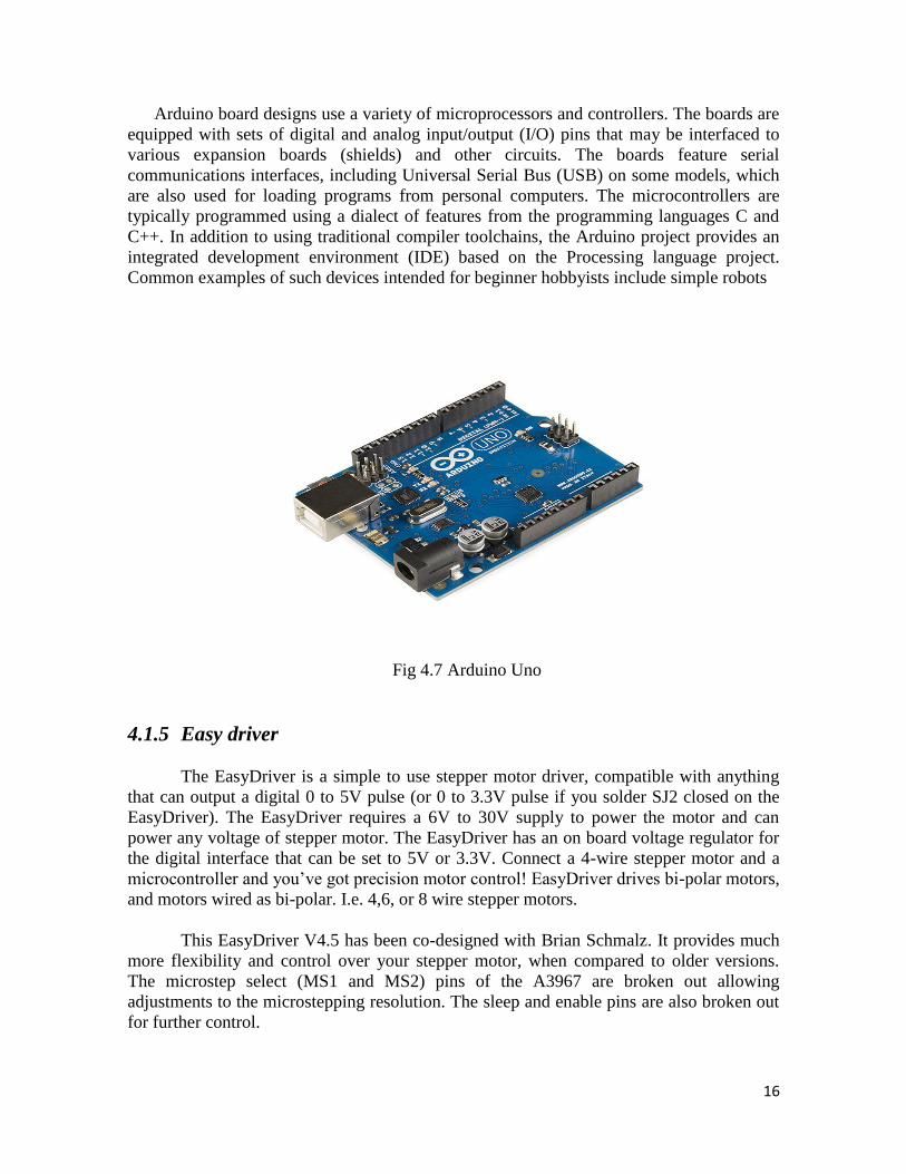
4.1.4 Arduiono uno Arduino is an open source, computer hardware and software company, project, and user
community that designs and manufactures microcontroller kits for building digital devices
and interactive objects that can sense and control objects in the physical world. The
project's products are distributed as open-source hardware and software, which are licensed
under the GNU Lesser General Public License (LGPL) or the GNU General Public License
(GPL), permitting the manufacture of Arduino boards and software distribution by anyone.
Arduino boards are available commercially in preassembled form, or as do-it-yourself kits.
16
Arduino board designs use a variety of microprocessors and controllers. The boards are
equipped with sets of digital and analog input/output (I/O) pins that may be interfaced to
various expansion boards (shields) and other circuits. The boards feature serial
communications interfaces, including Universal Serial Bus (USB) on some models, which
are also used for loading programs from personal computers. The microcontrollers are
typically programmed using a dialect of features from the programming languages C and
C++. In addition to using traditional compiler toolchains, the Arduino project provides an
integrated development environment (IDE) based on the Processing language project.
Common examples of such devices intended for beginner hobbyists include simple robots
Fig 4.7 Arduino Uno
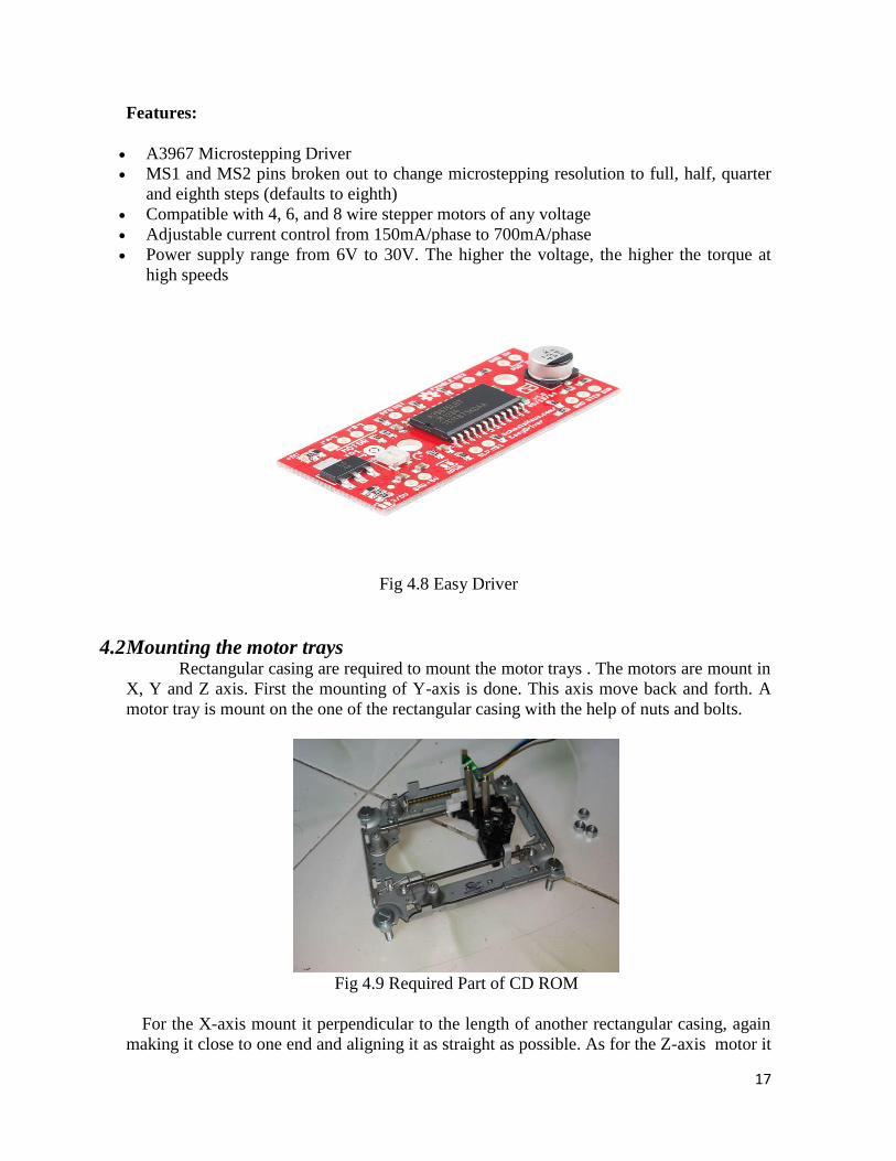
4.1.5 Easy driver
The EasyDriver is a simple to use stepper motor driver, compatible with anything
that can output a digital 0 to 5V pulse (or 0 to 3.3V pulse if you solder SJ2 closed on the
EasyDriver). The EasyDriver requires a 6V to 30V supply to power the motor and can
power any voltage of stepper motor. The EasyDriver has an on board voltage regulator for
the digital interface that can be set to 5V or 3.3V. Connect a 4-wire stepper motor and a
microcontroller and you‘ve got precision motor control! EasyDriver drives bi-polar motors,
and motors wired as bi-polar. I.e. 4,6, or 8 wire stepper motors.
This EasyDriver V4.5 has been co-designed with Brian Schmalz. It provides much
more flexibility and control over your stepper motor, when compared to older versions.
The microstep select (MS1 and MS2) pins of the A3967 are broken out allowing
adjustments to the microstepping resolution. The sleep and enable pins are also broken out
for further control.
17
Features:
A3967 Microstepping Driver
MS1 and MS2 pins broken out to change microstepping resolution to full, half, quarter
and eighth steps (defaults to eighth)
Compatible with 4, 6, and 8 wire stepper motors of any voltage
Adjustable current control from 150mA/phase to 700mA/phase
Power supply range from 6V to 30V. The higher the voltage, the higher the torque at
high speeds
Fig 4.8 Easy Driver
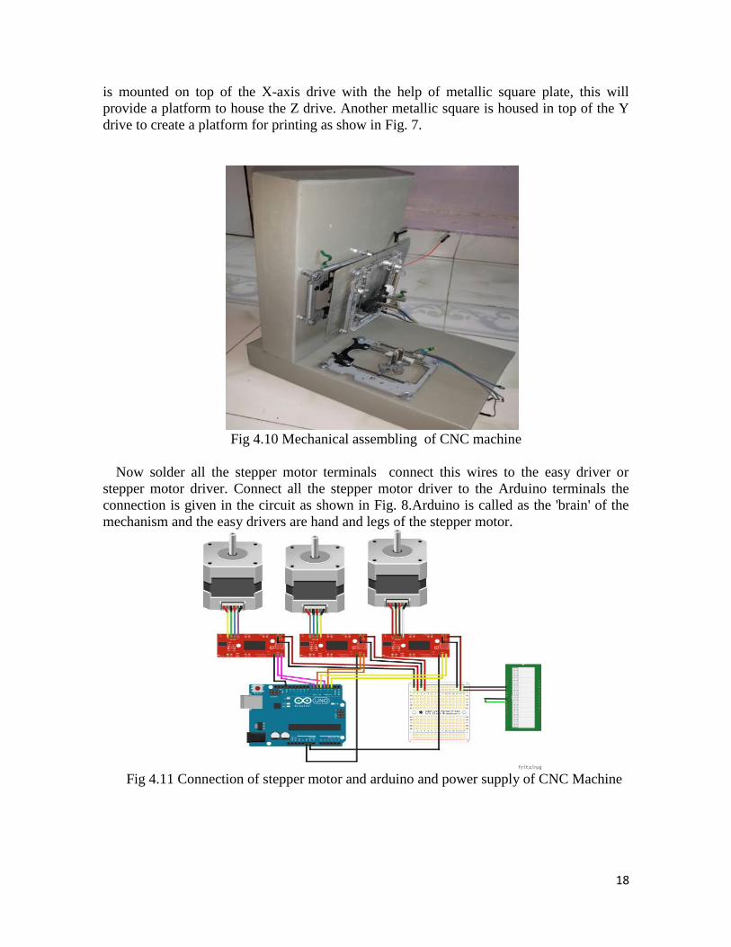
4.2 Mounting the motor trays Rectangular casing are required to mount the motor trays . The motors are mount in
X, Y and Z axis. First the mounting of Y-axis is done. This axis move back and forth. A
motor tray is mount on the one of the rectangular casing with the help of nuts and bolts.
Fig 4.9 Required Part of CD ROM
For the X-axis mount it perpendicular to the length of another rectangular casing, again
making it close to one end and aligning it as straight as possible. As for the Z-axis motor it
18
is mounted on top of the X-axis drive with the help of metallic square plate, this will
provide a platform to house the Z drive. Another metallic square is housed in top of the Y
drive to create a platform for printing as show in Fig. 7.
Fig 4.10 Mechanical assembling of CNC machine
Now solder all the stepper motor terminals connect this wires to the easy driver or
stepper motor driver. Connect all the stepper motor driver to the Arduino terminals the
connection is given in the circuit as shown in Fig. 8.Arduino is called as the 'brain' of the
mechanism and the easy drivers are hand and legs of the stepper motor.
Fig 4.11 Connection of stepper motor and arduino and power supply of CNC Machine
19
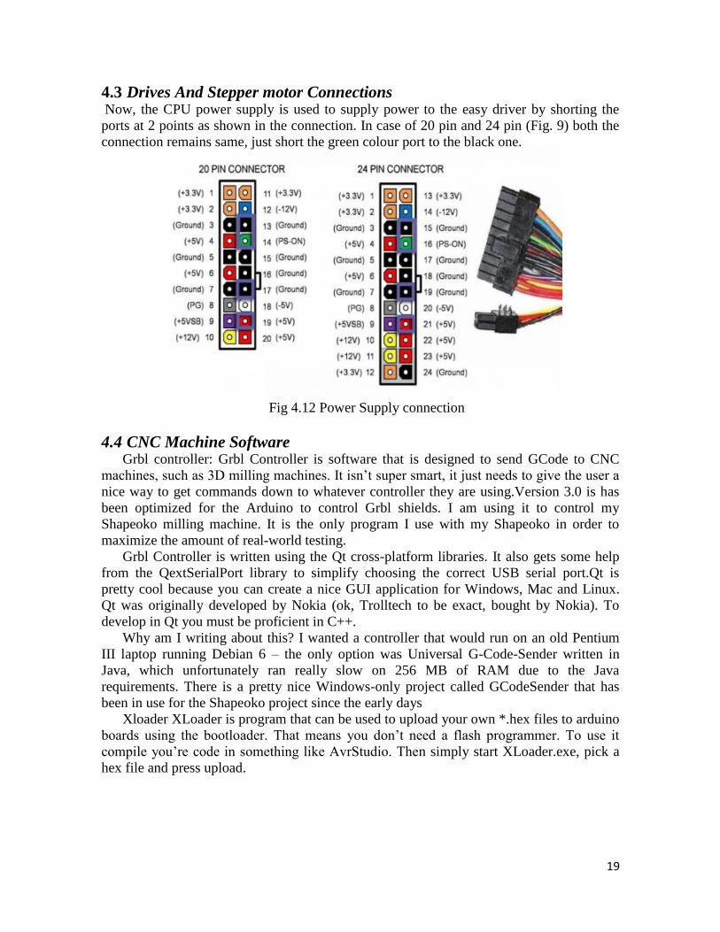
4.3 Drives And Stepper motor Connections Now, the CPU power supply is used to supply power to the easy driver by shorting the
ports at 2 points as shown in the connection. In case of 20 pin and 24 pin (Fig. 9) both the
connection remains same, just short the green colour port to the black one.
Fig 4.12 Power Supply connection
4.4 CNC Machine Software Grbl controller: Grbl Controller is software that is designed to send GCode to CNC
machines, such as 3D milling machines. It isn‘t super smart, it just needs to give the user a
nice way to get commands down to whatever controller they are using.Version 3.0 is has
been optimized for the Arduino to control Grbl shields. I am using it to control my
Shapeoko milling machine. It is the only program I use with my Shapeoko in order to
maximize the amount of real-world testing.
Grbl Controller is written using the Qt cross-platform libraries. It also gets some help
from the QextSerialPort library to simplify choosing the correct USB serial port.Qt is
pretty cool because you can create a nice GUI application for Windows, Mac and Linux.
Qt was originally developed by Nokia (ok, Trolltech to be exact, bought by Nokia). To
develop in Qt you must be proficient in C++.
Why am I writing about this? I wanted a controller that would run on an old Pentium
III laptop running Debian 6 – the only option was Universal G-Code-Sender written in
Java, which unfortunately ran really slow on 256 MB of RAM due to the Java
requirements. There is a pretty nice Windows-only project called GCodeSender that has
been in use for the Shapeoko project since the early days
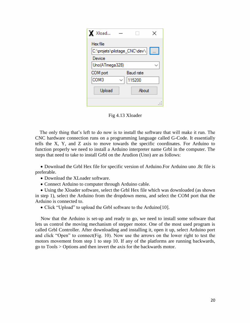
Xloader XLoader is program that can be used to upload your own *.hex files to arduino
boards using the bootloader. That means you don‘t need a flash programmer. To use it
compile you‘re code in something like AvrStudio. Then simply start XLoader.exe, pick a
hex file and press upload.
20
Fig 4.13 Xloader
The only thing that‘s left to do now is to install the software that will make it run. The
CNC hardware connection runs on a programming language called G-Code. It essentially
tells the X, Y, and Z axis to move towards the specific coordinates. For Arduino to
function properly we need to install a Arduino interpreter name Grbl in the computer. The
steps that need to take to install Grbl on the Arudion (Uno) are as follows:
Download the Grbl Hex file for specific version of Arduino.For Arduino uno .8c file is
preferable.
Download the XLoader software.
Connect Arduino to computer through Arduino cable.
Using the Xloader software, select the Grbl Hex file which was downloaded (as shown
in step 1), select the Arduino from the dropdown menu, and select the COM port that the
Arduino is connected to.
Click ―Upload‖ to upload the Grbl software to the Arduino[10].
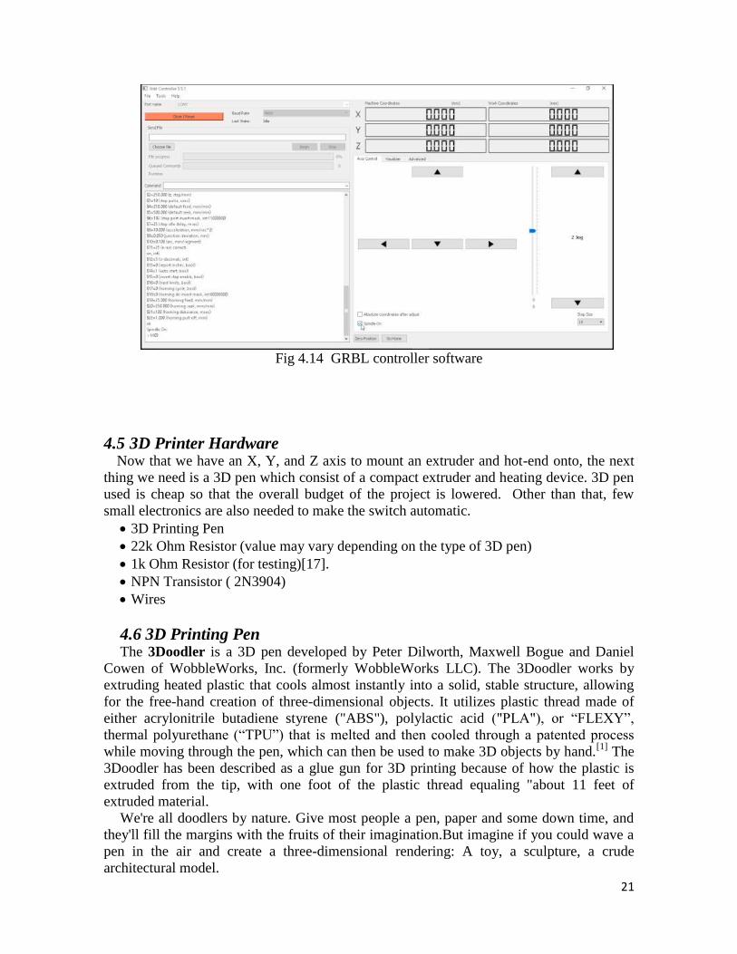
Now that the Arduino is set-up and ready to go, we need to install some software that
lets us control the moving mechanism of stepper motor. One of the most used program is
called Grbl Controller. After downloading and installing it, open it up, select Arduino port
and click ―Open‖ to connect(Fig. 10). Now use the arrows on the lower right to test the
motors movement from step 1 to step 10. If any of the platforms are running backwards,
go to Tools > Options and then invert the axis for the backwards motor.
21
Fig 4.14 GRBL controller software
4.5 3D Printer Hardware Now that we have an X, Y, and Z axis to mount an extruder and hot-end onto, the next
thing we need is a 3D pen which consist of a compact extruder and heating device. 3D pen
used is cheap so that the overall budget of the project is lowered. Other than that, few
small electronics are also needed to make the switch automatic.
3D Printing Pen
22k Ohm Resistor (value may vary depending on the type of 3D pen)
1k Ohm Resistor (for testing)[17].
NPN Transistor ( 2N3904)
Wires
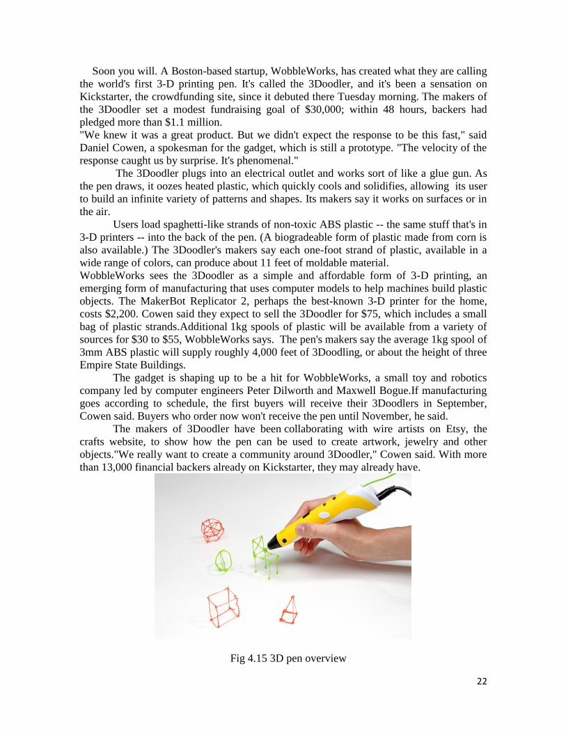
4.6 3D Printing Pen The 3Doodler is a 3D pen developed by Peter Dilworth, Maxwell Bogue and Daniel
Cowen of WobbleWorks, Inc. (formerly WobbleWorks LLC). The 3Doodler works by
extruding heated plastic that cools almost instantly into a solid, stable structure, allowing
for the free-hand creation of three-dimensional objects. It utilizes plastic thread made of
either acrylonitrile butadiene styrene ("ABS"), polylactic acid ("PLA"), or ―FLEXY‖,
thermal polyurethane (―TPU‖) that is melted and then cooled through a patented process
while moving through the pen, which can then be used to make 3D objects by hand.[1]
The
3Doodler has been described as a glue gun for 3D printing because of how the plastic is
extruded from the tip, with one foot of the plastic thread equaling "about 11 feet of
extruded material.
We're all doodlers by nature. Give most people a pen, paper and some down time, and
they'll fill the margins with the fruits of their imagination.But imagine if you could wave a
pen in the air and create a three-dimensional rendering: A toy, a sculpture, a crude
architectural model.
22
Soon you will. A Boston-based startup, WobbleWorks, has created what they are calling
the world's first 3-D printing pen. It's called the 3Doodler, and it's been a sensation on
Kickstarter, the crowdfunding site, since it debuted there Tuesday morning. The makers of
the 3Doodler set a modest fundraising goal of $30,000; within 48 hours, backers had
pledged more than $1.1 million.
"We knew it was a great product. But we didn't expect the response to be this fast," said
Daniel Cowen, a spokesman for the gadget, which is still a prototype. "The velocity of the
response caught us by surprise. It's phenomenal."
The 3Doodler plugs into an electrical outlet and works sort of like a glue gun. As
the pen draws, it oozes heated plastic, which quickly cools and solidifies, allowing its user
to build an infinite variety of patterns and shapes. Its makers say it works on surfaces or in
the air.
Users load spaghetti-like strands of non-toxic ABS plastic -- the same stuff that's in
3-D printers -- into the back of the pen. (A biogradeable form of plastic made from corn is
also available.) The 3Doodler's makers say each one-foot strand of plastic, available in a
wide range of colors, can produce about 11 feet of moldable material.
WobbleWorks sees the 3Doodler as a simple and affordable form of 3-D printing, an
emerging form of manufacturing that uses computer models to help machines build plastic
objects. The MakerBot Replicator 2, perhaps the best-known 3-D printer for the home,
costs $2,200. Cowen said they expect to sell the 3Doodler for $75, which includes a small
bag of plastic strands.Additional 1kg spools of plastic will be available from a variety of
sources for $30 to $55, WobbleWorks says. The pen's makers say the average 1kg spool of
3mm ABS plastic will supply roughly 4,000 feet of 3Doodling, or about the height of three
Empire State Buildings.
The gadget is shaping up to be a hit for WobbleWorks, a small toy and robotics
company led by computer engineers Peter Dilworth and Maxwell Bogue.If manufacturing
goes according to schedule, the first buyers will receive their 3Doodlers in September,
Cowen said. Buyers who order now won't receive the pen until November, he said.
The makers of 3Doodler have been collaborating with wire artists on Etsy, the
crafts website, to show how the pen can be used to create artwork, jewelry and other
objects."We really want to create a community around 3Doodler," Cowen said. With more
than 13,000 financial backers already on Kickstarter, they may already have.
Fig 4.15 3D pen overview
23
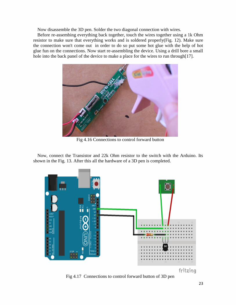
Now disassemble the 3D pen. Solder the two diagonal connection with wires.
Before re-assembing everything back together, touch the wires together using a 1k Ohm
resistor to make sure that everything works and is soldered properly(Fig. 12). Make sure
the connection won't come out in order to do so put some hot glue with the help of hot
glue fun on the connections. Now start re-assembling the device. Using a drill bore a small
hole into the back panel of the device to make a place for the wires to run through[17].
Fig 4.16 Connections to control forward button
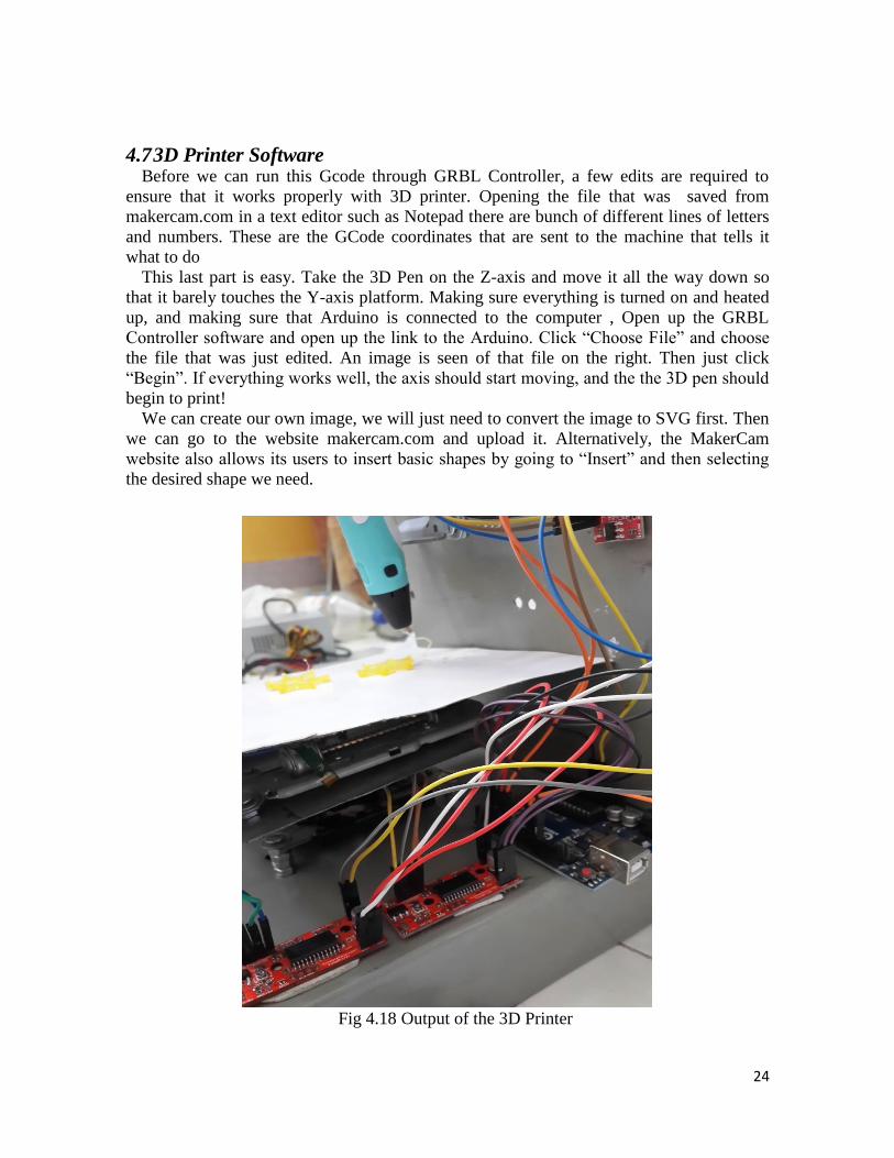
Now, connect the Transistor and 22k Ohm resistor to the switch with the Arduino. Its
shown in the Fig. 13. After this all the hardware of a 3D pen is completed.
Fig 4.17 Connections to control forward button of 3D pen
24
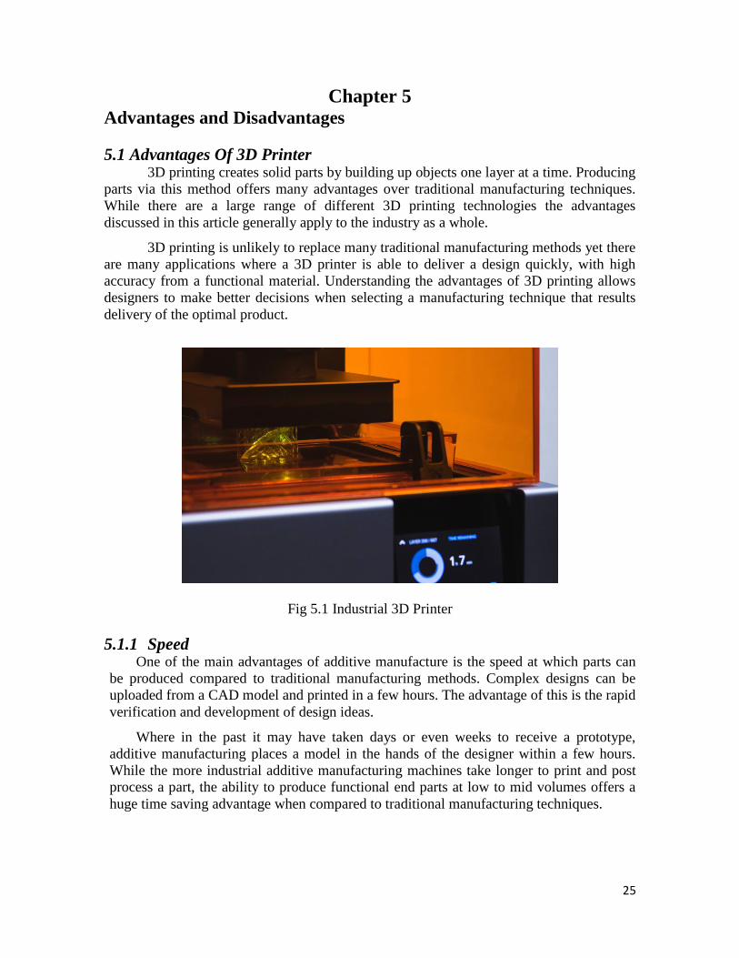
4.7 3D Printer Software Before we can run this Gcode through GRBL Controller, a few edits are required to
ensure that it works properly with 3D printer. Opening the file that was saved from
makercam.com in a text editor such as Notepad there are bunch of different lines of letters
and numbers. These are the GCode coordinates that are sent to the machine that tells it
what to do
This last part is easy. Take the 3D Pen on the Z-axis and move it all the way down so
that it barely touches the Y-axis platform. Making sure everything is turned on and heated
up, and making sure that Arduino is connected to the computer , Open up the GRBL
Controller software and open up the link to the Arduino. Click ―Choose File‖ and choose
the file that was just edited. An image is seen of that file on the right. Then just click
―Begin‖. If everything works well, the axis should start moving, and the the 3D pen should
begin to print!
We can create our own image, we will just need to convert the image to SVG first. Then
we can go to the website makercam.com and upload it. Alternatively, the MakerCam
website also allows its users to insert basic shapes by going to ―Insert‖ and then selecting
the desired shape we need.
Fig 4.18 Output of the 3D Printer
25
Chapter 5 Advantages and Disadvantages
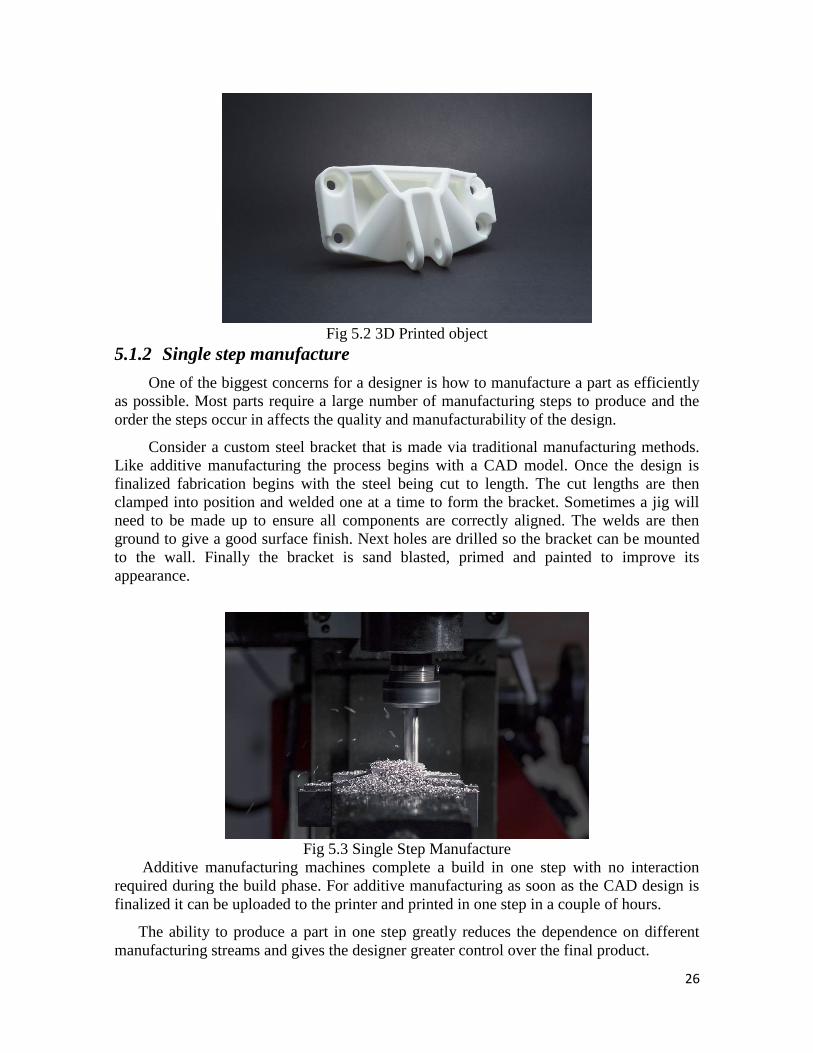
5.1 Advantages Of 3D Printer 3D printing creates solid parts by building up objects one layer at a time. Producing
parts via this method offers many advantages over traditional manufacturing techniques.
While there are a large range of different 3D printing technologies the advantages
discussed in this article generally apply to the industry as a whole.
3D printing is unlikely to replace many traditional manufacturing methods yet there
are many applications where a 3D printer is able to deliver a design quickly, with high
accuracy from a functional material. Understanding the advantages of 3D printing allows
designers to make better decisions when selecting a manufacturing technique that results
delivery of the optimal product.
Fig 5.1 Industrial 3D Printer
5.1.1 Speed One of the main advantages of additive manufacture is the speed at which parts can
be produced compared to traditional manufacturing methods. Complex designs can be
uploaded from a CAD model and printed in a few hours. The advantage of this is the rapid
verification and development of design ideas.
Where in the past it may have taken days or even weeks to receive a prototype,
additive manufacturing places a model in the hands of the designer within a few hours.
While the more industrial additive manufacturing machines take longer to print and post
process a part, the ability to produce functional end parts at low to mid volumes offers a
huge time saving advantage when compared to traditional manufacturing techniques.
26
Fig 5.2 3D Printed object
5.1.2 Single step manufacture
One of the biggest concerns for a designer is how to manufacture a part as efficiently
as possible. Most parts require a large number of manufacturing steps to produce and the
order the steps occur in affects the quality and manufacturability of the design.
Consider a custom steel bracket that is made via traditional manufacturing methods.
Like additive manufacturing the process begins with a CAD model. Once the design is
finalized fabrication begins with the steel being cut to length. The cut lengths are then
clamped into position and welded one at a time to form the bracket. Sometimes a jig will
need to be made up to ensure all components are correctly aligned. The welds are then
ground to give a good surface finish. Next holes are drilled so the bracket can be mounted
to the wall. Finally the bracket is sand blasted, primed and painted to improve its
appearance.
Fig 5.3 Single Step Manufacture
Additive manufacturing machines complete a build in one step with no interaction
required during the build phase. For additive manufacturing as soon as the CAD design is
finalized it can be uploaded to the printer and printed in one step in a couple of hours.
The ability to produce a part in one step greatly reduces the dependence on different
manufacturing streams and gives the designer greater control over the final product.
27
5.1.3 Cost
The cost of manufacture can be broken down into 3 categories; machine operation
costs, material cost and labor costs.
Machine operation costs: Most desktop 3D printers use the same amount of power as a
laptop computer. More industrial additive manufacturing technologies consume a high
amount of energy to produce a single part however the ability to produce complex
geometries in a single step results in higher efficiency and turnaround. Machine operation
costs are typically the lowest contributor to the overall cost of manufacture.
Material costs: The material cost for additive manufacturing varies significantly by
technology. Desktop FDM printers use filament coils that cost around $25 per kg while
SLA printing requires resin that retails around $150 per litre. The range of materials
available for additive manufacturing make quantifying a comparison with traditional
manufacturing difficult. Nylon powder used in SLS costs around $70 per kg while
comparable nylon pellets used in injection molding can be purchased for as little as $2 - $5
per kg. Material costs are the biggest contributor to the cost of a part made via additive
manufacturing.
Labor costs: One of the main advantages of 3D printing is the the cost of labor. Post
processing aside, the majority of 3D printers only require an operator to press a button. The
machine then follows a completely automated process to produce the part. Compared to
traditional manufacturing where highly skilled machinists and operators are typically
required, the labor costs for a 3D printer are almost zero.
Additive manufacturing at low volumes is very cost competitive compared to
traditional manufacturing. For the production of prototypes that verify form and fit, it is
significantly cheaper than other alternative manufacturing methods (injection molding) and
is often competitive for manufacturing one off functional parts. Traditional manufacturing
techniques become more cost effective as volumes begin to increase and the high setup
costs are justified by the large volumes of productions.
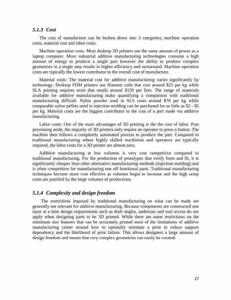
5.1.4 Complexity and design freedom
The restrictions imposed by traditional manufacturing on what can be made are
generally not relevant for additive manufacturing. Because components are constructed one
layer at a time design requirements such as draft angles, undercuts and tool access do not
apply when designing parts to be 3D printed. While there are some restrictions on the
minimum size features that can be accurately printed most of the limitations of additive
manufacturing center around how to optimally orientate a print to reduce support
dependency and the likelihood of print failure. This allows designers a large amount of
design freedom and means that very complex geometries can easily be created.
28
Fig 5.4 Less Complex
5.2 Disadvantages Of 3D Printer
3D printers have created amazing objects such as a violin, a dinosaur bone and even a
bionic ear. While the technology boasts mind-boggling potential, it's still relatively new
and has limitations. Before investing in a 3D printer or planning to develop a project on
one, you may want to consider the disadvantages of the process.
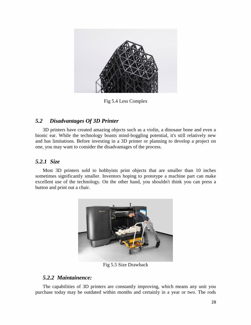
5.2.1 Size
Most 3D printers sold to hobbyists print objects that are smaller than 10 inches
sometimes significantly smaller. Inventors hoping to prototype a machine part can make
excellent use of the technology. On the other hand, you shouldn't think you can press a
button and print out a chair.
Fig 5.5 Size Drawback
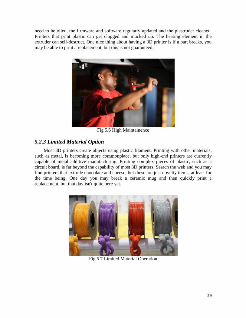
5.2.2 Maintainence:
The capabilities of 3D printers are constantly improving, which means any unit you
purchase today may be outdated within months and certainly in a year or two. The rods
29
need to be oiled, the firmware and software regularly updated and the plastruder cleaned.
Printers that print plastic can get clogged and mucked up. The heating element in the
extruder can self-destruct. One nice thing about having a 3D printer is if a part breaks, you
may be able to print a replacement, but this is not guaranteed.
Fig 5.6 High Maintainence
5.2.3 Limited Material Option
Most 3D printers create objects using plastic filament. Printing with other materials,
such as metal, is becoming more commonplace, but only high-end printers are currently
capable of metal additive manufacturing. Printing complex pieces of plastic, such as a
circuit board, is far beyond the capability of most 3D printers. Search the web and you may
find printers that extrude chocolate and cheese, but these are just novelty items, at least for
the time being. One day you may break a ceramic mug and then quickly print a
replacement, but that day isn't quite here yet.
Fig 5.7 Limited Material Operation
30
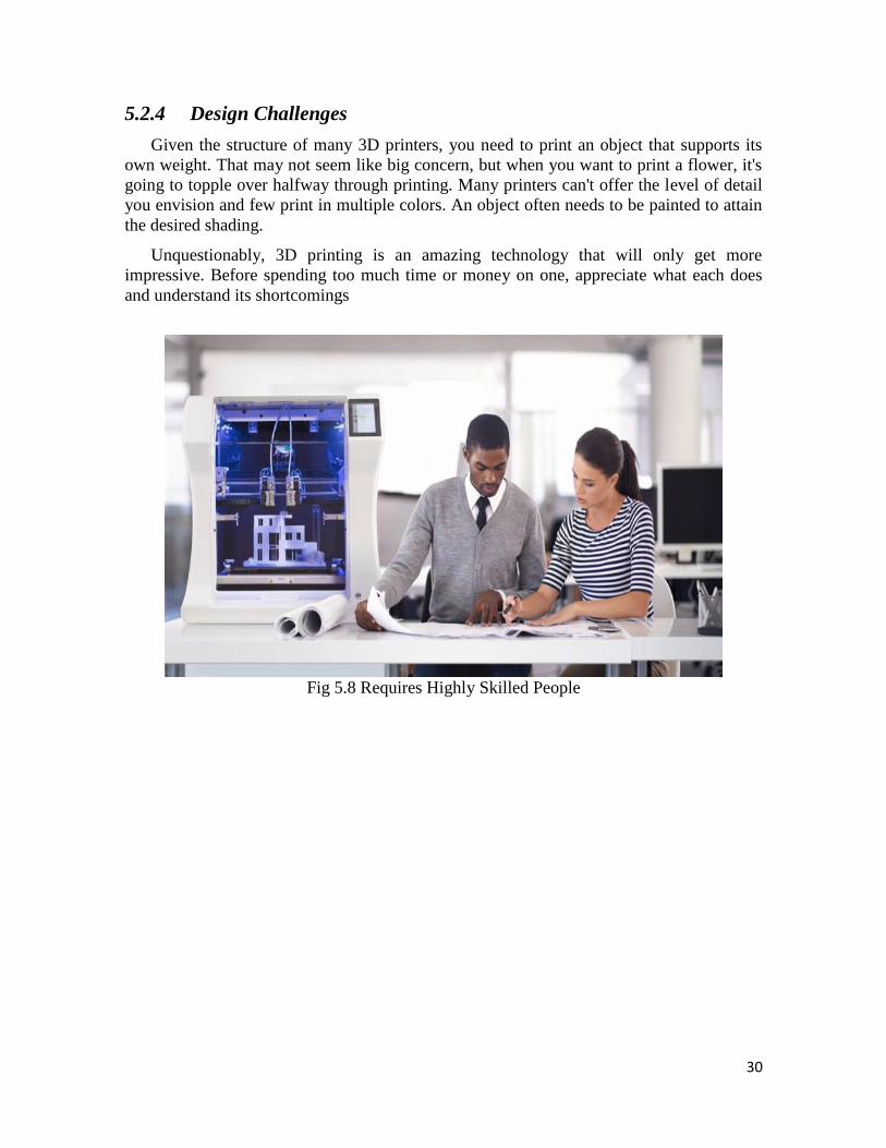
5.2.4 Design Challenges
Given the structure of many 3D printers, you need to print an object that supports its
own weight. That may not seem like big concern, but when you want to print a flower, it's
going to topple over halfway through printing. Many printers can't offer the level of detail
you envision and few print in multiple colors. An object often needs to be painted to attain
the desired shading.
Unquestionably, 3D printing is an amazing technology that will only get more
impressive. Before spending too much time or money on one, appreciate what each does
and understand its shortcomings
Fig 5.8 Requires Highly Skilled People
31
Chapter 6 Future Scope
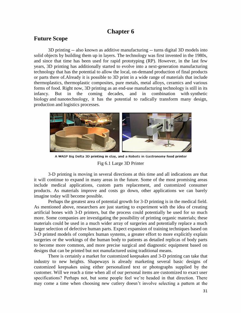
3D printing -- also known as additive manufacturing -- turns digital 3D models into
solid objects by building them up in layers. The technology was first invented in the 1980s,
and since that time has been used for rapid prototyping (RP). However, in the last few
years, 3D printing has additionally started to evolve into a next-generation manufacturing
technology that has the potential to allow the local, on-demand production of final products
or parts there of.Already it is possible to 3D print in a wide range of materials that include
thermoplastics, thermoplastic composites, pure metals, metal alloys, ceramics and various
forms of food. Right now, 3D printing as an end-use manufacturing technology is still in its
infancy. But in the coming decades, and in combination with synthetic
biology and nanotechnology, it has the potential to radically transform many design,
production and logistics processes.
Fig 6.1 Large 3D Printer
3-D printing is moving in several directions at this time and all indications are that
it will continue to expand in many areas in the future. Some of the most promising areas
include medical applications, custom parts replacement, and customized consumer
products. As materials improve and costs go down, other applications we can barely
imagine today will become possible.
Perhaps the greatest area of potential growth for 3-D printing is in the medical field.
As mentioned above, researchers are just starting to experiment with the idea of creating
artificial bones with 3-D printers, but the process could potentially be used for so much
more. Some companies are investigating the possibility of printing organic materials; these
materials could be used in a much wider array of surgeries and potentially replace a much
larger selection of defective human parts. Expect expansion of training techniques based on
3-D printed models of complex human systems, a greater effort to more explicitly explain
surgeries or the workings of the human body to patients as detailed replicas of body parts
to become more common, and more precise surgical and diagnostic equipment based on
designs that can be printed but not manufactured using traditional means.
There is certainly a market for customized keepsakes and 3-D printing can take that
industry to new heights. Shapeways is already marketing several basic designs of
customized keepsakes using either personalized text or photographs supplied by the
customer. Will we reach a time when all of our personal items are customized to exact user
specifications? Perhaps not, but some people feel we‘re headed in that direction. There
may come a time when choosing new cutlery doesn‘t involve selecting a pattern at the
32
store but designing it on your computer and printing out the resulting pieces. One day we
may dial up just the right level of edge for a child starting to use sharp knives, build
customized ergonomic handles that fit each individual‘s hands perfectly (perhaps color
coded for easy identification), or shape spoon bowls to generate the perfect mouthful every
time.
Another area of growth in the 3-D printing arena is replacement parts production.
Need a new screw for your laptop? A new gear for your heirloom grandfather clock? A
new piston for your car? Instead of trying to track down the part, pay for shipping, and
waiting weeks for its arrival, you‘ll just be able to print it out and go. Mechanics will keep
specs for every part of every car ever sold in a database and print out whatever they need
immediately with no difficulty. While it would save time and money for any part, it‘s a
particular boon for restoration jobs of all kinds where the original parts are extremely
difficult to find or may not even exist anymore.
Another intriguing area is customized food production. Evil Mad Scientist
Laboratories has created a low cost, low resolution capable of printing models made from
ordinary granulated sugar. We could soon see edible centerpieces, customized candy gifts,
novelty lollipops customized for gift shops attached to tourist attractions, or chocolate
sculptures rivaling the most complex ice sculptures out there. It‘s unclear exactly how far
we could go with printed food and if it will ever move out of the novelty area, but certainly
an area to watch in the future.
REAL WORLD EXAMPLES
3d Printing Has Far Reaching Potential And Is Already Starting To Disrupt The Biggest
And Most Important Industries And Markets In The World.
Some Of Them Are Listed Below:
6.1 Environment & Improve Sustainability
Fig 6.2 Environment Sustainability
From providing a tortoise with a new 3D-printed shell, to 3D printing solar cells and
wind turbines, 3D printing is protecting the environment and increasing our sustainability.
33
Not only that, but 3D printing in itself is a much more efficient way to manufacture
goods in comparison to the traditional manufacturing techniques that typically create a lot
of waste product.
6.2 3D Printing is Changing: Science, Research, and Education
Fig 6.3 3D Printing Research
Imagine showing your students a life-sized replica of a dinosaur bone and giving
them a hands-on learning experience, rather than relying on an image in a text book for
your lesson. With 3D printing, this is a possibility and it is how the technology is changing
the way we learn, research, and conduct studies. 3D printing is quickly getting adopted by
schools, universities, and research labs across the world in large part due to its ability to
produce affordable and complex models that aid in teaching and conducting research.
6.3 Advancing The: Aerospace, Aviation, & Automotive Industries.
Fig 6.4 3D printer Aplication
While 3D printing is having a big impact across a ton of different industries and
markets, perhaps none will be more important—when it‘s all said and done—than the
potential impact that it could have on the aerospace, aviation, and automotive industries.3D
printing is allowing aerospace companies, car makers, and airplane manufacturers to test
out new designs, prototype more effective parts, and build better machines at lower costs—
all of which are helping us travel further and cheaper than ever before.

34
6.4 The Enormous Impact That 3D Printing Is Having on General
Manufacturing.
Fig 6.5 Impact On General Manufactoring
While 3D printing is changing markets and industries that typically haven‘t been
linked to traditional manufacturing (like fashion and medicine), the technology
is still having a big impact on traditional manufacturing as well.From 3D printing in metal,
to printing out electronics, additive manufacturing is transitioning from being just a nice
new way to produce cost-effective prototypes into a fully-functioning manufacturing
outlet.
6.5 3D Print Your Own Home and Custom Home Décor.
Fig 6.6 3D Printed Homes
If you thought that 3D printing was just being used to create small plastic items, you
better think again. In fact, there are a handful of large-scale 3D printers across the world
that are actually printing out full-sized homes. Yes, you read that right… there are now 3D
35
printed homes. And, amazing as that is, 3D printing is also making big waves in the home
improvement and home decor industries by offering custom solutions at affordable prices.
So, whether you need a brand new concrete home (or mansion…) or some new decorations
to liven up your living space, 3D printing can help you out.
6.6 3D Printers Are Now Being Used In Culinary Arts and Cooking.
Fig 6.7 3D Printers in Culinary Arts
Hamburgers, pizza, pancakes, chocolate, and more… 3D printing has now entered
into the world of cooking and culinary arts and is helping expert chefs and novice cooks
make food in new and more creative ways. 3D printed food can also solve a host of issues
that come with traditional cooking, such as allowing astronauts to 3D print food in space,
creating intricately designed cakes, treats, and baked goods, and designing tasty food that
has specific nutritional values.
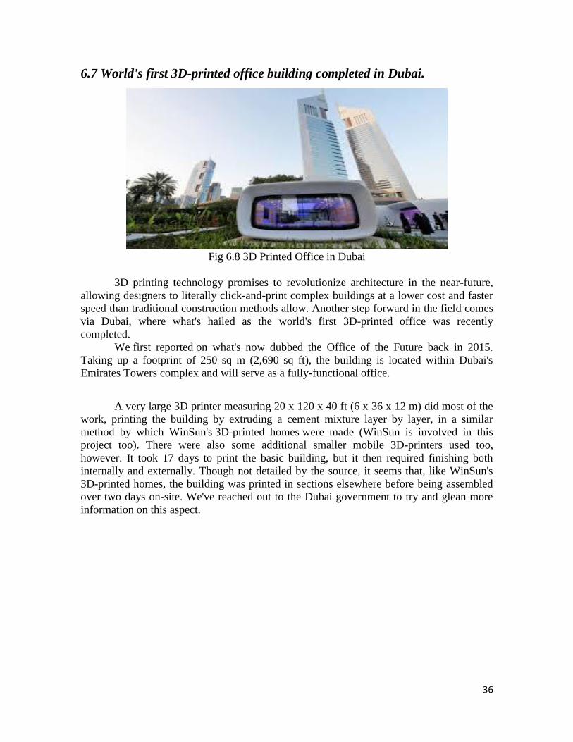
36
6.7 World's first 3D-printed office building completed in Dubai.
Fig 6.8 3D Printed Office in Dubai
3D printing technology promises to revolutionize architecture in the near-future,
allowing designers to literally click-and-print complex buildings at a lower cost and faster
speed than traditional construction methods allow. Another step forward in the field comes
via Dubai, where what's hailed as the world's first 3D-printed office was recently
completed.
We first reported on what's now dubbed the Office of the Future back in 2015.
Taking up a footprint of 250 sq m (2,690 sq ft), the building is located within Dubai's
Emirates Towers complex and will serve as a fully-functional office.
A very large 3D printer measuring 20 x 120 x 40 ft (6 x 36 x 12 m) did most of the
work, printing the building by extruding a cement mixture layer by layer, in a similar
method by which WinSun's 3D-printed homes were made (WinSun is involved in this
project too). There were also some additional smaller mobile 3D-printers used too,
however. It took 17 days to print the basic building, but it then required finishing both
internally and externally. Though not detailed by the source, it seems that, like WinSun's
3D-printed homes, the building was printed in sections elsewhere before being assembled
over two days on-site. We've reached out to the Dubai government to try and glean more
information on this aspect.
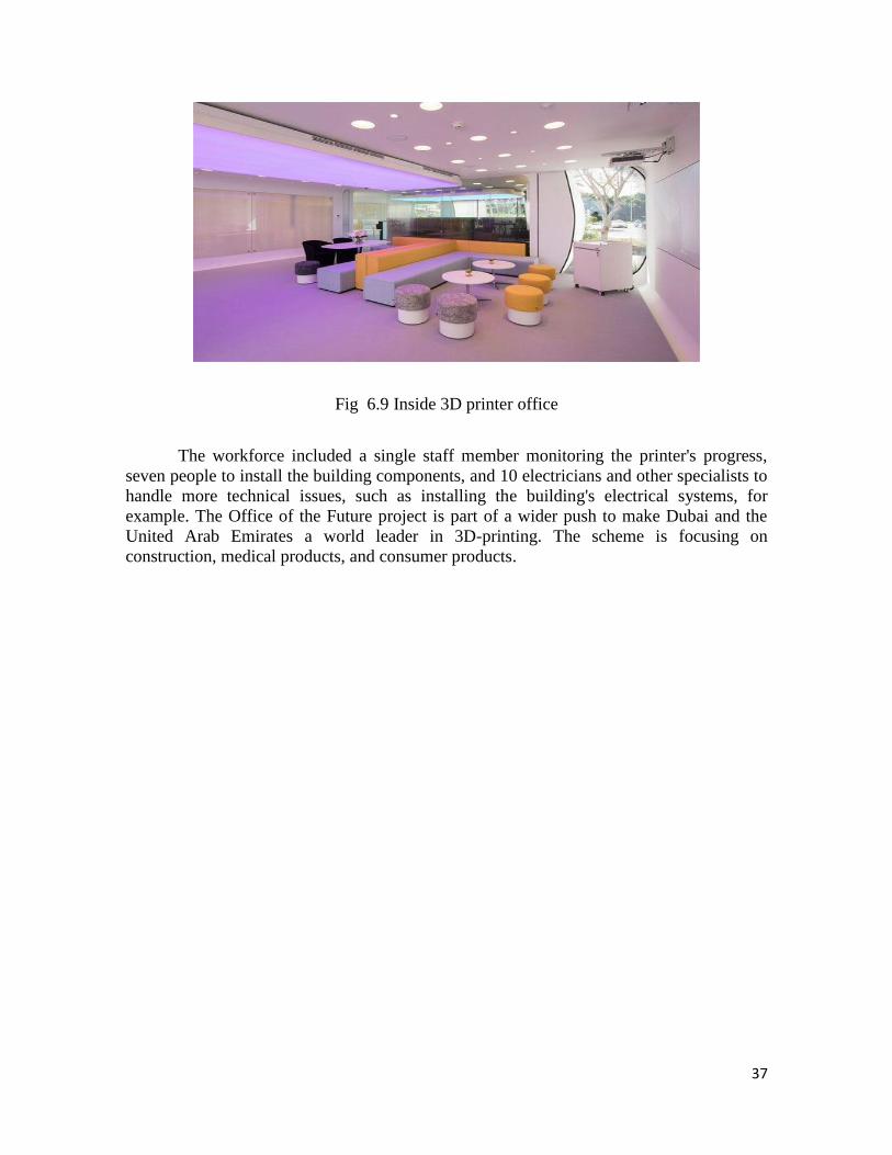
37
Fig 6.9 Inside 3D printer office
The workforce included a single staff member monitoring the printer's progress,
seven people to install the building components, and 10 electricians and other specialists to
handle more technical issues, such as installing the building's electrical systems, for
example. The Office of the Future project is part of a wider push to make Dubai and the
United Arab Emirates a world leader in 3D-printing. The scheme is focusing on
construction, medical products, and consumer products.

38
Chapter 7 Applications
The possibilities of 3D Printing for your product development and manufacturing are
endless.
Entertainment & Broadcasting
Industrial Goods
Optics
Robotics
Textile
Automotive
Drones
Mechanics
Food Industry
39
Chapter 8 Conclusion
It‟s easy to imagine a future where items manufactured in China will be
complemented with 3D printed customization in stores. Recent innovations using 3D
printers like within the biotech industry provide insight into both the significant market
advantages of high-value 3D-printed products and the significant initial costs to realize
those advantages. Once printers become commonplace in the home, one can conceive
printing custom glasses and plates for a dinner party.
3D printers when used to only available in science fiction stories is now a real
tangible product that used to create products.
In medicine, hospitals are already printing structural body components. In labs they
are working on printing out organs, though it will be a while before this becomes common.
Due to the price it's access to world is very limited but through this project there
will be an increase in the access of 3D printers. We made our own 3D printer with a price
of just 6000 Rs. If we can imagine it, we can also create it. The only limit is our
imagination.
40
References
[1] http://www.mechanicalhero.com/2011/11/cnc-computer-numeric-control.html
[2] http://www.toptenreviews.com/computers/articles/history-of-3D-printing
[3] https://redshift.autodesk.com/history-of-3D-printing
[4] https://3Dprintingindustry.com/3D-printing-basics-free-beginners-guide/history
[5] https://www.allthat3D.com/3D-printing-history
[6] Siddharth Bhandari,B Regina "International Journal of Computer Science and
Information Technology Research" Vol. 2, Issue 2, pp: (378-380), Month: April-June
2014
[7] http://3Dprintingforbeginners.com/3D-printing-technology
[8] Dipayan Dey,Souvik Mondal2,Arijit Kumar Barik "3-Axis CNC Router Modifiable to
3D Printer" International Journal of Innovative Research in Science, Engineering and
Technology Vol. 5, Issue 9, September 2016
[9] http://3Dprinting.com/what-is-3D-printing
[10] http://www.tinkernut.com/portfolio/hack-old-cd-roms-into-a-cnc-machine/
[11] https://learn.adafruit.com/all-about-stepper-motors/what-is-a-stepper-motor
[12] https://blog.dragoninnovation.com/2014/12/30/top-10-benefits-3D-printing-salient-
technologies/
[13] http://www.forbes.com/sites/amitchowdhry/2013/10/08/what-can-3D-printing-do-
here-are-6-creative-examples/#27b0600d61b0
[14] https://www.quora.com/What-are-the-future-prospects-of-a-3D-printing-company-in-
India
[15] http://www.fabricegrinda.com/business-musings/3D-printing-will-change-the-world/
[16] http://www.tinkernut.com/portfolio/how-to-make-a-cheap-3d-printer/