Embed Size (px)
Citation preview

Student Guide v09.01.16

Table of Contents
Chapter 1 Colorless Core Architecture Chapter 2 OSPFv3 Chapter 3 DMVPN Chapter 4 Multicast Chapter 5 Quality of Service (QoS) Chapter 6 Access Control Lists

INSERT TAB #1 HERE

Colorless Core Architecture

2
3
WIN-T Incremental Release
The Warfighter Information Network, Tactical (WIN-T) is a 4-stage incremental fielding of communication assets that is IP centric. Each of the increments provides different roles to forces:
• Connectivity: Commercial and military frequency Satellite Communications (SATCOM) to division, brigade and battalion.
• Equipment: Radios, Routers, Servers, Encryption, Modems, Antennas (transportable) • Capability: Enables quality voice, data and limited video communications at-the-halt.
Provides for coordinated actions between geographically separated units. Increment 1 provides networking at the halt to the forces using a combination of routers, firewalls and smart multiplexors. Increment 1a provides enhanced networking at-the-halt. •The former JNN program with Ka military satellite communications capability •The former JNN program with Net Centric Waveform and Colorless Core Capability Increment 2 provides the initial networking on the move (OTM) down the company level with limited wireless integration RDT&E for Solder Network Extension (SNE), High Capacity Network Radio (HNR), Tactical Communications Node (TCN), Points of Presence (PoPs) and other associated Configuration Items (CIs) Procurement of limited numbers of SNE, HNR, TCN, PoP and other associated CIs Increment 3 provides full networking capabilities OTM with full wireless integration. Full mobility to include Future Combat Systems (FCS) support Increment 4 the final in the series provides protected satellite communication between echelons on the battlefield Protected Satellite Communications (SATCOM) on the Move Enhanced capability for protected SATCOM through tech inserts from High Capacity Communication Capability (HC3)

4
WIN-T Inc 1 ExistingSystems Architecture Overview
Mission Statement: WWaarrffiigghhtteerr IInnffoorrmmaattiioonn NNeettwwoorrkk –– TTaaccttiiccaall (WIN-T) is the Army’s current and future tactical network that will provide seamless, assured, mobile communications for the warfighter along with advanced network management tools to support implementation of commander’s intent and priorities – incrementally. Increment 1 provides “Networking At-The-Halt” capability down to battalion level with a follow-on “Enhanced Networking At-The-Halt” (Inc 1b) to improve efficiency and encryption to divisions, brigades and battalions. WIN-T Increment 1 components reside at the division, brigade and battalion levels. Description State of The Art COTS/GOTS For The Current Force Connects The Warfighter To The Global Information Grid DISN Connectivity Down To Battalion Level Enhanced Mobility And Communications At The Quick Halt Joint And Coalition Connectivity Provided Interface To Legacy Systems Encrypted SIPRNET Traffic Through the NIPRNET SATCOM & Terrestrial Termination Autonomous Brigade Operations Benefits/Capabilities
• Supports Modularity by allowing a Brigade Combat Team to have self sustaining reach back communications
• Provides internet infrastructure connectivity directly to the Battalion level • Transitions Army Networks from proprietary protocols to “EVERYTHING OVER IP”
(EOIP) • Allows independent mobility of command posts and centers unconstrained by Line of
Sight radio ranges • Incorporates industry standards for network operations and intrusion detection

5
WIN-T Inc 1Networking at the Halt
The WIN-T increment 1 architecture builds on the original JNN network design. As it has become the initial increment for WIN-T, it has matured to the point where tactical units rely on it for their primary means of at the halt communications. Additional TOC communications platforms utilize the WIN-T system as their wide area network interconnections. WIN-T increment 1 consist of two platforms for TOC communications – the Joint Network Node (JNN) and Battalion Command Post Node (BnCPN). The tactical and regional Hub nodes act as WAN interconnection points for the entire network. The Satellite Transportable Terminal (STT) provides TDMA support to the JNN and BnCPN as well as FDMA for the JNN and is considered the primary means of communications for these systems. The WIN-T Inc 1 network employs a variety of transmission methods to pass voice, data and video throughout the network. This communications system is utilized by tactical army units at all levels – from corps down to battalion. The two primary means of communications, FDMA and TDMA (both satellite-based), are typically used to provide the backbone links between WIN-T Inc 1 elements. In addition, cable, Line-Of-Sight radio, Ground Mobile Forces (GMF) TACSAT, Secure Mobile Anti-jam Reliable Terminal-Tactical (SMART-T), and Troposcatter radio systems augment these basic capabilities. It should be noted that all fielded versions of equipment currently employed communicate with one another throughout the Network providing voice and data capabilities to supported units. This is done primarily through a consistent dynamically-routed network using the OSPF protocol. The TACLANE provides bulk NSA type 1 encryption throughout the network for all classifications of traffic beyond NIPR, with the majority of the bandwidth dedicated to SIPR-based traffic.

6
Multiplexed TDM
Multiplexed TDM Both the JNN and hub node assemblages make use of FDMA communications routed over the Promina smart multiplexing system, which has the capability of combining encrypted voice, video, and data circuits over a single pipe. The Promina is also able to provide end-to-end communications to systems not directly connected, as well as rerouting traffic over different paths if the active path goes down. In addition, this also provides a transport for specialized communication circuits such as video teleconferencing and ISDN or T-1 voice channels. Through the employment of the LOS Transit Case, the Battalion CPN case can employ serial-based communications, but no multiplexing. While this allows for increased dedicated bandwidth, flexibility, and redundancy between two sites, it may also lead to wasted bandwidth if there is not a need for communication between those sites. Circuit and TDM-based systems also require the router to maintain separate serial interfaces for each communication endpoint as well.

7
EoIP – Everything over IP
WIN-T Inc 1
EoIP – Everything over IP • Preferred transport uses convergence routing for Everything over IP architecture. • Promina function and PBX not available in JNN(v)6 • Certain “OLD” technologies will fall aside. Example would be the DRSN DPM 128K
termination box. • No serial interfaces on Tier2 SIPR in LOT 10. FDMA link between JNN and Hub Node
terminates at NIPR T2 Router serial port.
NOTE: TACLANEs employed to tunnel SIPR thru NIPR as the primary path. Additional TACLANE remains in the JNN, but is rarely used to tunnel NIPR thru SIPR. ARCHITECTURAL REASONS FOR CONVERGED SERIAL LINK DESIGN Preferred connectivity scheme uses a converged serial link to the HUB HUB has only two SA-TRK’s for Promina Transport – but they must be patched in to use HUB can receive IP traffic over FDMA from aannyy WIN-T Inc 1 or Legacy models Converged scheme also wired in SSS(v)4 WHY NOT ABANDON PROMINA CAPABILITY AND JUST USE CONVERGED SERIAL?
• Converged link cannot carry non-IP based traffic, e.g., legacy Defense Red Switch Network (DRSN), H.320
• Allows our JNN(v)4,(v)5 to connect to “pre-Inc 1 HUB” systems • Provides Promina capability to missions requiring Promina connectivity • HUB or JNN connectivity for PBX traffic to Defense Information Systems Agency (DISA)
Bottom Line: WIN-T Inc 1 supports both capabilities.

8
Fixed Regional Hub Node(FRHN)
The Fixed Regional Hub Node (FRHN) is a non-transportable and permanently installed system within a strategic STEP (Standardized Tactical Entry Point) or Teleport site. FRHN systems will be established at several geographic regions worldwide. It is designed to augment the existing Joint Network Node (JNN) network architecture by providing services currently provided by the Tactical Hub Node. The FRHN will serve the following primary purposes:
1. Provide JNN-enabled Army divisions access to GIG/DISN services during the initial deployment and recovery operations when their THN is not readily available.
2. Provide backup or redundant services to the THN. 3. Provide standalone JNN-enabled Brigade Combat Teams (BCT), which do not possess a
THN system access to GIG/DISN services.
The FHRN system is designed to support three separate JNN-enabled Army divisions and up to four standalone BCT’s through satellite connectivity to other JNN Network systems: Tactical Hub Node (THN), Joint Network Node (JNN), and Battalion Command Post Node (BnCPN). The FRHN will support both Frequency Division Multiple Access (FDMA) and Time Division Multiple Access (TDMA) satellite links. Equipment is grouped into “enclaves” within the FHRN facility as depicted below. Each enclave will operate independently from one another. SIPR Enclave: Interfaces RHN to DISN SIPR data services. These services are then provided to the Division/BCT enclaves. NIPR Enclave: Interfaces RHN to DISN NIPR data and voice (DSN) services. These services are then provided to the Division/BCT enclaves. Division Enclaves: Division enclaves are the direct interface from the RHN to divisional communications systems deployed on the battlefield. Through this enclave, DISN, SIPR, and NIPR services are provided to battlefield users.

9
BCT Separate Enclaves: BCT Separate enclaves are designed to provided DISN, SIPR, and NIPR services to deployed BCTs, which are stand alone and not part of a deployed division. Promina & DED/TED Enclave: This enclave provides multiplexing and encryption functions for serial data communications links between the RHN and deployed divisions and/or standalone BCTs.

10
Division Hub Node(Spirals 2 and Beyond)
The Tactical Hub Node acts as the “Tier 0” for divisional communications assemblages. It will serve as a “Surrogate Teleport” as well as a “DATA PIPE” between all fielded systems. The THN is a deployable communications support package that integrates, manages, and controls a variety of communications interfaces between the various echelons’ communications assets within the network. It also provides access to the Defense Information System Network (DISN) terrestrial and tactical satellite communications (SATCOM). The high mobility and bandwidth is accomplished with the employment of a complex suite of satellite systems. When fully populated, the THN can support a division network of 16 FDMA links and 16 TDMA nets. Baseband Equipment
• Border Router (S, N) • Antivirus (S,N) • Tier 2 Router (S,N) • Promina NX-1000 • Ethernet Switch (S, N) • KIV-7M • Management Laptops (S, N) • PBX (Redcom HDX) • TCP Proxy (S, N) • CTM-100s • Call Control (Call Manager) (S, N) • FECs • Terminal Server (S, N) • Pairgain Modems • HAIPE (v 1.3.5) (Quantity 2) • Flex Mux • Perimeter Firewall / IPS (S, N) • GPS Receive and GPS antenna • Host Lan Firewall / IPS (S,N) • Vantage

11
Brigade Node (JNN)
M1152 (ECV)
M1097 2.4M Ku
M1097
M1097
HMTM1102M1097
Nodal Mgt
NIPRSIPR
IP Phone CasesBVTC/BITS
CasesSIPR AccessCases w/UPS
NIPR AccessCases w/UPS
8 Phones 8 Phones 8 Phones
10 KWGenerator
Printer
TFOCA (100m)
TFOCA (300m)
24 Phones
POTS
NIPRSIPR
KG-175DKIV-7M
Brigade Node (JNN) • COTS switching routing at the Div, BCT, and BN • Interfaces with HCLOS LOS Asset • Interfaces with SATCOM Assets (X,C,Ku band), both GMF and Commercial systems • Circuit switch to Joint Services and VOIP for internal subscribers • Subscriber voice, video, and data services to medium size force elements • 2.4M Ku/Ka Ready trailerized SATCOM (FDMA and TDMA) • Direct reach back capabilities to higher command and strategic enclaves • Up to 8 Megabits per second bandwidth pipe from Div to BCT LOS • Up to 3 Megabits per second FDMA SATCOM • Shared bursts up to 4 Megabits to the small CPs • Simultaneous STEP/JOINT Interfaces to include NIPR/SIPR • Two simultaneous DTG connections to legacy MSE nodes • Hosts H.323 video conferences and is compatible with DCTS • Secret and DSN voice subscribers
Brigade Node (JNN) Capabilities
• ATH TDMA/FDMA via STT • ATH interface to STEP/Teleport, Current Force, DSN, Trusted PSTN, CENTRIX, JWICS,
SIPR, NIPR, THSDN • ATH interface to LOS(V)1, LOS(V3), TROPO • ATH interface to SMART-T, GMF, and commercial SATCOM assets • Secret Services (VOIP, Data, VTC) • SI Services (VOIP, Data, VTC, PBX/POTS) • Analog Services • Internal Enclave Boundary Protection (Tier1/Tier2 SIPR/NIPR) • IPv4/IPV6

12
• C-130 transportable INC-1b Capabilities
• ATH TDMA/FDMA via STT • ATH interface to STEP/Teleport, Current Force, DSN, Trusted PSTN, CENTRIX, JWICS,
SIPR, NIPR, THSDN • ATH interface to LOS(V)1, LOS(V3), TROPO • ATH interface to SMART-T, GMF, and commercial SATCOM assets • Secret Services (VOIP, Data, VTC) • SI Services (VOIP, Data, VTC, PBX/POTS) • Analog Services • Internal Enclave Boundary Protection (Tier1/Tier2 SIPR/NIPR) • IPv4/IPV6 • C-130 transportable • Colorless Core
LOS Capabilities
• Supports 2 X Band 1 or 2 X Band 3 links to a max quantity of 3 links • 16 Mbps (full duplex) AN/GRC-245 HCLOS Radio • RF Interface to: LOS(V)1, LOS(V)3 • Cable Interface: DS3 FOM TFOCA 1 or CX11230 to JNN shelter
Packaging/SWAP
• LMS on 2.5 Ton FMTV or M1152HMMWV with B2 Armor Kit • 18K ECU • 10 KW Towed Generator
GFE/GFS
• HMWWV or FMTV • CHS-III Components • COMSEC
Employment
• ESB (4), Corps/Div HQ (3), SBCT/BCT (2), Bde (1) Baseband
• Border Router (S, N) • Tier 2 Router (S,N) • Ethernet Switch (S, N) • Management Laptops (S, N) • TCP Proxy (S, N) • Call Control (Call Manager) (S, N) • Terminal Server (S, N) • HAIPE (v 1.3.5) (Quantity 2) • Perimeter Firewall / IPS (S, N) • Host Lan Firewall / IPS (S,N) • Antivirus (S,N) • Promina NX-1000 • KIV-7M • PBX (Redcom Slice) • CTM-100s • FECs • Pairgain Modems • Flex Mux • GPS Receive and GPS antenna • Vantage

13
WIN-T Inc 1 Assemblages
HDX
New architecture of the communication assemblages All JNN versions have complete cable and SEP components. The only differences are module population for future upgrade in designs. Equipment design is composed of a mixture from a common module set representing functional groups. The architecture employs common module design between different assemblages to enforce common internal architectures. The module design removes most of the complex patch panel configurations inherent in earlier designs. JNN (V)4/5/6, SSS(V)4 and Tactical Hub are built from these modules to meet their respective network requirements. WIN-T Inc1 JNNs have three versions offering specific architecture requirements. JNN (V)4 is equipped with the MSE, NIPR, SIPR, STEP and Transmission Modules. Training is centered around this module because of the commonality between other modules JNN (V)5 is equipped with the STEP, NIPR, SIPR and Transmission Modules. JNN (V)6 is equip with the NIPR, SIPR and Transmission Modules.

14
Modules
Modules are designed to accommodate a specific network function and maintain a common component makeup between shelter platforms. The majority of the unique modules are found in the Increment 1 TacHub, which has not yet been widely fielded.
• Router - two sets - one for SIPR and one for NIPR - both include the Tier 2 router and switch
• Transmission - Consists of Patch Panel, FLEXMUX, T1 Configuration panel and CDIM modems
• STEP -Consists of Promina NX-1000, Redcom SLICE, KIV-7M, and pairgain modems • Tactical Switch - Includes SMU and COMSEC module • MSE Interface - Vantage switching system

15
Battalion Command Post Node(Bn CPN)
M1097 2.4m Ku M1097
NetOps Package for BnCPN
1 per BnCPN
LANMgmt
10-kW Generator
(SIPR/NIPR) RouterCases, UPS
IP PhoneCase
Transit Case Based Equipment
LANMgmt
8 PhonesKG 175D
NIPRSIPR
Call Manager
TFOCA (100m)TFOCA (300m)
LOS Case
The BnCPN provides: • Enhanced voice and data capabilities at support battalions • SIPR/NIPR and devices and access (up to 20 data and IP telephony users) • Capability to interface directly to Ku/Ka satellite or Line-of-Sight radio transmission
resources The BnCPN suite of communications equipment is housed in transit cases:
• SIPR/NIPR data interface transit case w/ TACLANE • Red voice interface using Cisco IP phones • LAN/Network management resources
Capabilities
• Ku/Ka TDMA SATCOM ATH (STT) • Interface to LOS • Node Mgmnt (S, SI) • Support for 2-Wire Analog STEs • Supports SI and S LAN extension (for user LAN VOIP, video, or data devices) • Serial and Ethernet Interface to BVTC • Initial QoS • Enclave Protection • IPv4 / v6 when HAIPE V3 is available • C-130 Transportable

16
Packaging/SWAP • 18K ECU • 10 KW Towed Generator
GFE/GFS
• CHS-III Components • COMSEC
Employment
• ESB (24), Corps/Div HQ (18), SBCT/BCT (12), Bde (6) Baseband
• Tier 2 Router (S,N) • Ethernet Switch (S, N) • 2 Management Laptops (S, N) • TCP Proxy (S, N) • 2 Call Control (Call Manager Laptops) (S, N) • HAIPE (v 1.3.5) (Quantity 1) • Host Lan Firewall / IPS (S,N)
User Access
• User access switches (S, N) • 2 wire IP Gateways (S, N)
Router Case
• Tier 2 Router (S, N) • 2 wire IP Gateways (S, N)
Future Equipment Changes:
• Replacement of Netscreen Fire/Wall (F/W) with CISCO Adaptive Security Appliance (ASA)-5500 Series
• Replacement of Call Manager Express (CME) with full Call Manager • New TACLANE micro (KG-175D), replacement of Key Interface Variable (KIV)-19 with
KIV-7M • Minor connector changes

17
Satellite Transportable Terminal (STT)
Environmentally sealed electronic enclosure with integral rack mounts and
cooling
Environmentally sealed electronic enclosure with integral rack mounts and
cooling
7.5 KW Back up Generator7.5 KW Back up Generator
Rear Leveling jacks for stabilization w/large pads for loose soil
conditions
Rear Leveling jacks for stabilization w/large pads for loose soil
conditionsAir Conditioner and Storage areaAir Conditioner and Storage area
Front leveling jack used in conjunction with 2 rear jacks
for leveling
Front leveling jack used in conjunction with 2 rear jacks
for leveling
Shock antenna boom rest with integrated aerial lifting points. Out riggers stow to
side of structure
Shock antenna boom rest with integrated aerial lifting points. Out riggers stow to
side of structure
The Satellite Transportable Terminal (STT) is a satellite terminal system providing two-way digital communications in support of the WIN-T architecture. The STT is located at the Corp/Division and Brigade Combat Team (BCT) level. The terminal consists of a 2.4 meter Ku antenna mounted on a trailer. The electronic components that provide two-way digital communications are mounted in two electronic equipment racks located in a cooled electronics equipment compartment on the rear of the trailer. INC-1 &1B Capabilities
• Ka/Ku Capable SATCOM • MIL STD 188-165A FDMA ATH • Linkway TDMA ATH • NCW ATH • Interface TFOCA 2 • IPV4/IPV6 • C-130 Transportable

18
STT Equipment Rack
AES 2811 Router
AES 2811 Router
CTM-100/C Modem
CTM-100/C Modem
Linkway S2 TDMA Modem
Linkway S2 TDMA Modem
RadyneFDMA Modem
RadyneFDMA Modem
323T Antenna Control
Unit
323T Antenna Control
Unit
M&C SystemM&C
System
Patch PanelPatch Panel
ECU Controler
ECU Controler
123T Power
Drive Unit
123T Power
Drive Unit
D-Link Gigabit Switch
D-Link Gigabit Switch
10MHz Reference RMR-1004
10MHz Reference RMR-1004
MPM-1000 Modem
MPM-1000 Modem
Electrical equipment is housed in two rack mount shelves in the rear compartment. Patch Panel – RF patch panel allows integration of MRT push package if needed, as well as in-system signal monitoring. 10MhZ Reference – Provides Stratum 1 timing source for the communications systems within the trailer. 323T ACU – Includes many functions consolidated over various upgrades including GPS receiver, spectrum analyzer and beacon receive and tracking. D-Link GB switch – Most if not all equipment within the STT is now IP-capable and managed via the M&C computer. To maximize throughput, all systems connect via this gigabit ethernet switch. 123T Power Drive Unit – Acts as the mechanical antennae controller for dish positioning and tracking. ECU Controller – Thermostat and control for the air conditioning system. M&C System – The laptop that acts as the heart of the system for installation, operation, and maintenance of the communications equipment. CTM-100/C – Serial NRZ to Fiber Optic conversion for use in the JNN FDMA-equipped trailers. AES 2811 Router – Acts as the IPSEC tunnel endpoint for the Linkway IP-based satellite communications.

19
MPM-1000 – Installed as part of the Inc 1b upgrade package. The MPM-1 acts as the Network Centric Waveform component. Radyne FDMA Modem – Used in the JNN version of the STT for point-to-point serial communications link. Linkway S2 – Upgraded version of the Linkway modem that allows for communications to both the LW2100 as well as the higher speed S2 model.

20
WIN-T Inc 2 Network Layout
WIN-T Increment 2 is a secure, information-centric, spectrum agile network with an Internet Protocol (IP) core backbone supporting symmetric and asymmetric information dissemination. It utilizes next generation ground-to-ground and ground-to-space communication links capable of meeting the demanding requirements of modern tactical battlefield communications. WIN-T provides a converged IP network supporting voice, video, and data with differentiated services to support Warfighter Quality of Service (QoS) and Speed of Service (SoS) requirements. The converged IP backbone is colorless (all user data is encrypted prior to being placed on the backbone), and supports dynamic bandwidth allocation and is cryptographically isolated from all external networks. NOSC-D v1 (Network Operations & Security Center-Division) Capabilities
• Full division-level Planning and Network Management • Topology Generator • Coverage Planning for wireless LANs, LAW, HNW, NCW, and HCLOS radios in support
of CAMC2, TCN, JNN, BNN, 802.11 transit case, Generic Emitter. • Information Assurance monitoring, and administration • Spectrum Planning for all known emitters and Management of Network emitters • Enroute Mission Planning • Support for PKI • Battle Command Address Book Planning
TR-T v1 (Tactical Relay-Tower version 1) Capabilities
• ATH High-capacity C Band G-to-G HNW • Provides maximum G-to-G range via improved LOS • C-130 Transportable
VWP v1 Package Vehicle Wireless

21
WIN-T Inc 2 Equipment Layout
Major elements of the WIN-T architecture include the Tactical Communications Node (TCN), Network Operations and Security Center (NOSC), Modular Communications Node (MCN), Joint Gateway Node (JGN), Tactical Relay (TR), Point of Presence (PoP), Vehicle Wireless Package (VWP), IP Telephones, and the Soldier Network Extension (SNE). WIN-T Increment 2 includes upgrade kits for the STT+ and regional Hubs. WIN-T Increment 2 also includes power generators, support vehicles, and other items required to operate the system TCN v1 – The TCN v1 provides advanced antenna technologies providing full OTM capabilities for all mobile Command Center (CC) applications on-the-move (OTM). In high capacity static applications such as Division Command Posts (DCPs), increased at-the-halt (ATH) throughput capabilities are provided using towed SATCOM terminals. It is employed throughout the operational environment from battalion through division levels in support of mobile CPs. JGNv1 - The Joint Gateway Node version 1 (JGN v1) is a set of transit cased modules that provide integrated gateway capability for Joint, Allied/Coalition (North Atlantic Treaty Organization [NATO]/Non-NATO), Commercial, Modular Force, Defense Information Systems Network (DISN), Trojan Network, and other Government Agencies. In addition, the JGN v1 provides Time Division Multiplexing (TDM), Commercial T1/E1, Allied, and Coalition interfaces. PoP v1: The PoP v1 B-Kit configuration provides ATH and OTM high capacity ground-to-ground LOS communications as well as Ka/Ku SATCOM. Basic user services are provided in the PoP v1 on the Secret LAN, while extended user services are provided remotely. SNE v1: The SNE v1 B-Kit configuration provides ATH and OTM Ka/Ku SATCOM. An optional LAN side CNR interface can also be supported by the SNE v1.

22
TRT v1 - The TR-T v1 is a towed trailer with 30 m mast that is dismounted during operation. The TR-T v1 provides Highband Radio Frequency Unit (HRFU), which is connected to the TR-T v1’s Baseband Processing Unit (BPU). Together these form the HNR radio. The TR-T v1 provides extended Ground-to-Ground communications range where needed.

23
NOSC-D & NOSC-B
100BTX
PP
TFOCAII
TFOCAII
SI NetOps Security Domain
IP Connection
Console Port
Cable Connection
Guide
KVM Connection
SUN 4100 Server
SUN 4100 Server
SUN 4100 Server
SUN 4100 Server
SUN 4100 Server
100FX
1000LXEth Sw (24 Port)
(8) NetOps Laptops
UPS
100BTX
100BTX
PP
TFOCAII
TFOCAII
SE NetOps Security Domain
SUN 4100 Server
SUN 4100 Server
SUN 4100 Server
SUN 4100 Server
SUN 4100 Server
100FX
1000LXEth Sw (24 Port)
UPS
100BTX
100BTX
PP
TFOCAII
TFOCAII
SUN 4100 Server
SUN 4100 Server
100FX
1000LXEth Sw (24 Port)
UPS100BTX
CO NetOps Security Domain
KVM Tray
KVM Tray
KVM Tray
Network Operations (NetOps) management of the WIN-T network is provided by Network Operations and Security Center version 1 (NOSC v1) nodes (transit cased equipment), which provide centralized planning, administration, monitoring, and response functions. Each NOSC v1 node supports the NetOps management function by planning, administering, monitoring, and responding to network and subscriber services access, routing and switching (both within the local Command Center (CC) and across the WAN). The NOSC v1 nodes are transit cased assemblages providing WIN-T network management to the CC. The NOSC v1 node obtains subscriber services at both the SI and secret levels for operators from a TCN v1 that is co-located with the NOSC v1 node.
24
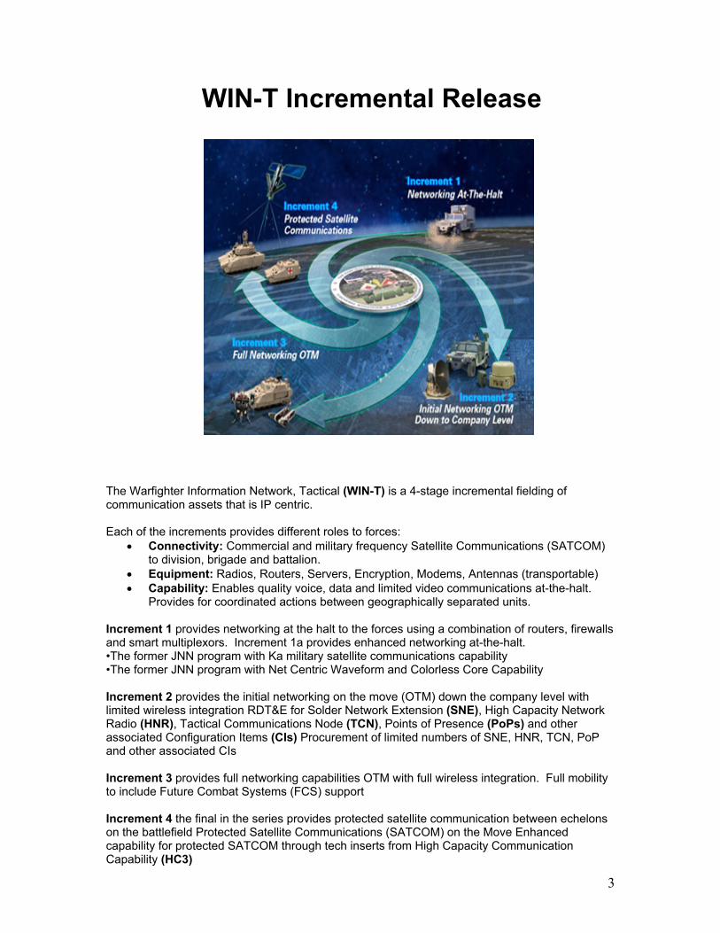
Tactical Communications Node TCNv1 & MCN-B
The functional core of the WIN-T network is provided by Tactical Communications Node version 1, which provide subscriber and network access, services routing and switching (both within the local CC and across the WAN), directory services, authentication services, and transmission systems. The Tactical Communications Node version 1 (TCN v1) is the basic core of the WIN-T network, providing WIN-T access and services to Division and BCTs. The TCN v1 has the capability to interface with a tactical satellite terminal such as SMART-T and existing LOS assets such as HCLOS. The TCN v1 provides ATH interfaces to CENTRIX (tunneled interface via the WIN-T WAN), trusted Army networks, and trusted converged Joint entities. The TCN v1 is a dedicated vehicle/assemblage providing WIN-T communications to the Command Center (CC). The TCN v1 provides direct subscriber access at both the SI and secret levels. Separate services and local management functions are provided, separated by security level. The TCN v1 is supported by a crew of four. The Modular Communications Node-Basic version 1 (MCN-B v1) is intended to be deployed into a tent or building, providing subscriber access to co-located CC cells. The MCN-B v1 is a suite of transit cases, which consists of two sets of cases each containing a 48 port Ethernet switch, a 24 port 2-wire analog telephone gateway, and a power conditioner/UPS. Connection of a MCN-B v1 into the WIN-T network is via tactical fiber optic cables connecting via a SEP to the SI or Secret LAN of a TCN v1. Capabilities
• OTM/ATH High-capacity C Band G-to-G HNW, Ka/Ku Band SATCOM NCW, SWLAN (S or SI), LAW
• GIG IA Compliant (Colorless Core) • ATH Interface to CENTRIX / Converged Joint / SMART-T / Phoenix / TSC-85/93s /
HCLOS v1/v3 • Node Management (CO, S, SI); LAN Management (S, SI) • Initial Dynamic Link Management

25
• Supports SI and S LAN extension (for user LAN VOIP, video, or data devices) • 2 x MCN-B will be providing wired user access • User Services (DNS, DHCP, Voice) • IP Gateway for Analog phones • Internal Enclave Boundary Protection • QoS w/ Congestion Control • IPv4 / IPv6 (Ready) • NSA Approved TRANSEC • C-130 transportable

26
Joint Gateway Node
The JGN v1 is typically installed at the Division and Corps levels. The JGN v1 is equipped with routing, switching, and full gateway capability for existing Army, Joint, Commercial, and Allied interfaces. The JGN v1 accommodates a variety of local operations including voice, local LAN management, directory services, and authentication services. Separate services and local management functions have been provided, separated by security level. The JGN v1 consists of transit-cased modules. The JGN v1 is supported by a crew of three soldiers. Capabilities
• Interface to CENTRIX, Joint, Allied, Commercial, DISN/GIG-BE, STEP/Teleport, Current Force, SMART-T, Phoenix, TSC-85/93s
• IPv4 / IPv6 (Ready) • Internal Enclave Boundary Protection and Host/AIS Protection • Multiplexer • External Boundary Protection

27
POP v1 & SNE v1
PoP_ FCS Vehicle_LRIP v2
POP v1
SNE v1
The Point of Presence version 1 (POP v1) is a WIN-T B-kit that is integrated into a combat platform to provide reach and reach back communications and connectivity into the WIN-T infrastructure. WIN-T provides the backbone transport for these vehicles. Connectivity to lower echelons is done with existing radios (e.g. SINCGARS, EPLRS) and JTRS radios when available. The Point of Presence version 1 (POP v1) is a B-Kit that is provided for the Modular Force and is typically deployed from platoon through division levels. Capabilities
• OTM/ATH High-capacity C Band G-to-G HNW, Ka/Ku-Band SATCOM NCW • Node Mgmnt (CO) • Initial Dynamic Link Management • IPv4 / IPv6 (Ready) • DNS/DHCP services provided in PoP (S or SI) • Local Call Control • QoS w/ Congestion Control
The Soldier Network Extension version 1 (SNE v1) is a WIN-T Ka/Ku B-Kit communications package for select vehicles at the Battalion/Company level. It provides OTM Ku SATCOM connectivity to the WIN-T network. The SNE v1 also provides a Combat Net Gateway function connecting SINCGARS voice networks to the WIN-T wide area network for a subset of the SNEs. The Soldier Network Extension version 1 (SNE v1) is a B-Kit that is provided for the Modular Force and is typically deployed in platoon command vehicles.

28
Vehicle Wireless Package
S of t back _LR I Pv2
Base Station
TCN v1
Subscriber Station
Subscriber Station
The Vehicle Wireless Package version 1 (VWP v1) is a B-Kit that provides subscriber access and is embedded in non-signal C2 platforms. It provides wireless local area access to all C2 vehicles in the CC area. Wired access to local users is provided via switched Ethernet. Internal to the vehicle, connectivity for up to 24 data terminals or WIN-T-provided VoIP wired phones is provided (either SI level or Secret level). Wireless connectivity to the WIN-T network is provided via the Local Access Waveform (LAW). Capabilities
• OTM/ATH Connectivity for Select Command Vehicles • LAW connectivity to TCN v1 • Point to multi-point network topology • 24 port user access

29
SATCOM Lay Down & NCW Nets
WIN-T has a rich SATCOM capability. In Increment 2, the MPM-1000 will support the Net-Centric Waveform (NCW) that can support a full mesh capability for a brigade sized network. The WIN-T system has a family of Ka/Ku antennas. It has small terminals for on-the-move communications (TCN, PoP, and SNE) and larger terminals for at-the-halt (STT+). The actual performance of these terminals is an effective tradeoff of transponder usage and the combination of OTM and ATH terminals. The WIN-T system has several defining requirements. These include:
• 256 Kbps on-the-move user data rate at 25 mph over cross country terrain (PoP and TCN).
• 64 Kbps to 128 Kbps (layer 2/3 interface) at 20 mph over improved road (SNE). The High capacity Network Waveform HNW has terrestrial LOS RF links operating at C-band with burst data rates up to 30 Mbps, with adaptive modulation modes, frequency, coding, and power levels, depending on factors such as distance, terrain, or interference. A TCN or a PoP supports multiple links to all other TCNs or PoP within the field of view. During the course of the Limited Users Test, two separate Ku networks will be used – the “yellow” and “green” networks. In order to access both networks, a separate modem would be needed for each. For those terminals that have only one modem, they must communicate via a tandem Ming node to the other network.

30
The WIN-T Increment 2 network implements a self-healing network based on the communications goals and priorities set by the managers at the Network Operations & Security Cell. As links between sites are formed, the system continually checks for the best path available, using them after a short stability check. If the links drop, traffic is rerouted over an available backup link. Priorities can be based on operational practices or available bandwidth on a given medium. In the example above, the TCN has available an FDMA and two NCW paths. The smaller radome indicates the OTM dish, which is not normally used when the larger ATH dish is available. The larger dish provides a larger pipe to the TCN site while the FDMA modem provides a large amount of dedicated bandwidth between the TCN and Regional Hub Node. The network architecture is implemented using OSPF version 3 for the Colorless Core and OSPF version 2 for the NIPR and SIPR networks. Both versions are manipulated in the WIN-T network using per-link costing to override the normal bandwidth-based cost calculation.

31
WIN-T Inc 1b Systems Architecture Overview

32
WIN-T Inc 1b Capability
MPM-1000MPM-1000
+
WIN-T Increment 1b Capability Enhanced Networking at-the-Halt: Increment 1a and JNN components upgraded with Net Centric Waveform and Colorless Core Capability Connectivity: Commercial and military band SATCOM to division, brigade and battalion. Equipment: Radios, routers, servers, encryption (send unclassified and classified data over the same path), modems (wideband modem for efficient operation over satellites), antennas (transportable) Capability: Enables more efficient wideband communications at-the-halt. Supports the distribution of intelligence, surveillance, and reconnaissance information via voice, data, and limited video to tactical operation centers at the halt. Improved unit coordination and synchronization. Ability to close on objective in less time with fewer losses.
• No modification of unit equipment • INC1B capability provided by temporary equipment insertion and configuration file
changes only • Colorless Core for NCW only

33

34
JNN Increment 1b Surrogate Design
PT
CT
PT
CT
Required Tunnels and
configuratio
n to
communicate w/Inc 2

35
BnCPN Increment 1b Surrogate Design
NIPR Router Case(Sp 2-7: Bn Case B)
For DT/LUT Only
SIPR Router Case(Sp 2-7: Bn Case A)
Vlan 175
Vlan 175
Vlan 6
Vlan 6
SEP
TLNT2R
NIPR AdaptiveRouter Case
STTLinkway
MPM-100
TLST2R
SIPR AdaptiveRouter Case
Colorless Router Case
3560
CLR
M/C
M/C
M/C
M/C
M/CNT2R
100BaseTX (Copper)TFOCA-II100BaseFX (Fiber)
Required Tunnels and
configuratio
n to
communicate w/Inc 2
ST2R
• The MPM-1000 in the STT will bypass the Cisco 2811 Router and connect directly to an available Media Converter connected to the second TFOCA-II SEP appearance (J2).
• The Colorless Router Case will connect to STT via TFOCA-II. • NIPR and SIPR Router Cases will connect to JNN and BnCPN via standard Vlan 6 interface
using TFOCA-II. • NIPR and SIPR Router Cases will connect to Colorless Router Case via 100BaseTX • Router Cases have two (2) 100BaseFX ports
o One is required to connect to the STT o Only one (1) remains for the two (2) Router Case connections
• The SIPR Router Case may be connected to Colorless Router Case via fiber if required

36
STT Wiring Changes
All lot 9 and beyond terminals, as well as most of those that have gone through the RESET program, are pre-wired to receive the NCW upgrade. This allows for relatively simple insertion of the MPM-1000 modem into the already-fielded STT trailers. Actual installation of the modem will be performed by the field support representative.

37
NCW Management
NMSNCW HCI
A laptop with NCW HCI software connects to E-net switch in Colorless Router Case. Initialize and manage NCW in-band via Dataport connection to MPM-1000. If provided, Increment 2 NMS laptop can connect to the E-net switch in Colorless Router Case

SIPRTL MICRO
NIPRTL MICRO
3825
3825 3825
10.119.16.237
G0/1.10610.119.16.236/16
G0/1.175 10.110.70.33
CT 10.110.70.34
PT 10.233.70.195/29
G0/2 VLAN 175G0/1 VLAN 175
G0/1 10.233.70.193/29
G0/0.6 172.28.79.200/16
CT 10.110.70.35
PT 10.231.70.195/29
G0/1 10.231.70.193/29
G0/51G0/51
W1BCOLORLESS
CASE
G0/48 TRUNK
G0/0.6 172.28.79.200/16
G0/48 G0/48
MPM-1000
G0/51
SIPRData
Case B
STT TRAILER
W1B SIPR CASE
W1B NIPR CASE
JNN(V2) SHELTER
J1/PR2 FDMATO PROMINA
J1/PR1 TDMATO ROUTER
NIPR Data
Case B
JNN TL
JNN NT2RL0 144.104.26.226
F2/7 TRUNK
F2/8
TRUNK PORT TRUNK PORT
100BSX2
100BSX1
3825
VPN RTRL0 144.104.26.228
SEP
JNN ST2RL0
22.214.243.226F2/8
PT 172.20.144.10CT 172.19.144.13
PROMINA
CDIM
STT VPRL0 144.104.26.229
SEPJ1SEP
J2
F2/7 TRUNK
LINKWAY MODEM
F0/010.210.144.10/29
TDMA Tunnel 6715172.21.144.2/26
WIN-T INC 1BJNN-67150FT STEWART
VLAN 106
TFOCA II
TFOCA II
W1B ST2RL0 148.34.28.25
W1B NT2RL0 143.194.16.19
F0/0172.19.144.14/30
W1B ST2S W1B NT2S
F2/0 172.28.144.199/16
F1/1 172.20.144.9/303825
XT2RL0 10.110.126.49
Fa1/0/37 Fa1/0/41Fa1/0/37Fa1/0/41
Fa1/0/37
3560G
T6700 G0/1 172.21.224.233/24T7731 G0/1 172.21.16.233/24
T6700 G0/1 172.21.224.233/24T7731 G0/1 172.21.16.233/24
Vlan 6 Vlan 6
F2/13S0/1S0/4
MP2A4J2
MP2A4J1
3825 MP2A4J2
MP2A4J1
MP3A1J1
KIV-7/1
KIV-19/10
WAN MGR WAN MGR
STT-67150-XNDM
MC2811
MC
F0/1/1
SIPRTL MICRO
NIPRTL MICRO
3825
3825 3825
SIPRTL
10.119.16.239
G0/1.10610.119.16.238/16
G0/1.175 10.110.69.33
CT 10.110.69.34
PT 10.233.69.195/29
G0/2 VLAN 175G0/1 VLAN 175
G0/1 10.233.69.193/29
G0/0.6 172.28.79.3/16
CT 10.110.69.35
PT 10.231.69.195/29
2651
CPN NT2RL0 144.104.28.242
CPN ST2RL0 22.214.248.226
CT 172.19.144.21/30
PT 172.20.144.31/30
VLAN 6
VLAN 6
J1 TO W1B NIPR
G0/51G0/47
W1B ST2S
F1/0/21
CPN SIPRCASE
G0/48
G0/48 G0/48
G0/49 TRUNK
2811
MPM-1000
G0/51
W1B SIPR CASE
W1B NIPR CASE
W1BCOLORLESS
CASE
CPN STT TRAILER
CPN NIPRCASE
G0/1 10.231.69.193/29
F0/0.6 172.28.144.1/16
TFOCA II
F0/1.175 172.19.144.22/30
G0/0.6 172.28.79.3/16
SEPJ1
SEPJ2 STT NVPR
L0 144.104.28.245
LINKWAY MODEM
F0/0 10.210.144.18/29
WIN-T INC 1BCPN-67152FT STEWART
TFOCA II
VLAN 106
XT2S
XT2RL0 10.110.126.65
W1B ST2RL0 148.34.28.26 W1B NT2R
L0 143.194.16.20
W1B NT2S
F0/0.175172.20.144.17/30
F1/0/19
Tunnel 6715172.21.144.3/26
Tunnel 6715172.21.144.3/26
CPNNT2S
CPNST2S
STT-67152-XNDM
LAN MGR
LAN MgrF1/0/18
F1/0/17
Fa1/0/18
Fa1/0/17
Fa1/0/37 3560G
T6700 G0/1 172.21.224.234/24T7731 G0/1 172.21.16.234/24 T6700 G0/1 172.21.224.234/24
T7731 G0/1 172.21.16.234/24
F0/0 172.28.144.1/16
X1
2651
MC
MC

2950 Ethernet Switch
Netscreen 5XT
Port 1Port 3
FO Med. Conv
Slot 0FE0/0
Slot 0FE0/1
2651 Ntier 2 Rtr
FO Med. Conv
TFOCAII
Cipher Text
Plain Text
3750 Ethernet Switch
2651 Router
Turbo IP
Netscreen 5XT
Port 1
Port 3
23X
20X 1X
VLAN 58/59
24X
21X
VLAN175
VLAN 60
VLAN 59
VLAN 60.1Q Trunk
User Connection
Web CacheSlot 1FE 0/0
19X
FO Med.Conv
Slot 0FE0/0
Slot 0FE0/1
WAN
LAN
BTN CP Router Case
BnCP VPN Case
FO MC3
2811 VPN Router
Part of STT
VLAN1
VLAN 1/58/175,222
SER0/0
22X
23X1X
24X
VLAN 1/58/60,175,222
CTM 100C
TX Port A
Port BTXRX
RX Port B
Port A
J1
FDMA Modem
TDMA Modem
NCW Modem
J2
CDUData
TACLANE
FO MC1
FO MC2
G0/51
G0/49 G0/48
G0/0G0/1
CT
PT
W1B NT2S
W1B NT2R
W1B NIPR Case
TACLANE
G0/47G0/48
G0/0 G0/1
CT
PT
W1B ST2S
W1B ST2R
W1B SIPR Case
G0/51
G0/49
G0/48
G0/0
W1B XT2S
W1B XT2RW1B NIPR Case
G0/2 G0/1
TFOCA2
TACLANE

43X 44X 45X 46X 47X 48X37X 38X 39X 40X 41X 42X31X 32X 33X 34X 35X 36X25X 26X 27X 29X 30X28
19X 20X 21X 22X 23X 24X13X 14X 15X 16X 17X 18X7X 8X 9X 10X 11X 12X1X 2X 3X 4X 5X 6X
WIN-T Increment 1bSIPR WIB Patching Diagram
TFOCAII
TFOCAII
100BFX
TFOCAII
TFOCAII
TFOCAII
1000BLX
TL-CT
SFP1 G0/49FIREWALL ROUTER
CONSOLE
3825 SERIAL 0 3825 SERIAL 1
0/0 0/1 0/2 0/3 G0/0 G0/1SFP2 G0/51
SFP3 G0/50 SFP4 G0/523825 3560 FW WAN opt
FWMGMT
IPSMGMT
WAN opt.INLINE
aPB.1 aPB.2aPA.1 Primary
WAN opt.REDIRECT
WAN opt.MGMT
PT
TACLANE
To SIPR BnCP 1/0/19
CT Interface of TaclaneWIB Colorless Ethernet
Switch G0/1

43X 44X 45X 46X 47X 48X37X 38X 39X 40X 41X 42X31X 32X 33X 34X 35X 36X25X 26X 27X 29X 30X28
19X 20X 21X 22X 23X 24X13X 14X 15X 16X 17X 18X7X 8X 9X 10X 11X 12X1X 2X 3X 4X 5X 6X
WIN-T Increment 1bNIPR WIB Patching Diagram
TFOCAII
TFOCAII
100BFX
TFOCAII
TFOCAII
TFOCAII
1000BLX
TL-CT
SFP1 G0/49FIREWALL ROUTER
CONSOLE
3825 SERIAL 0 3825 SERIAL 1
0/0 0/1 0/2 0/3 G0/0 G0/1SFP2 G0/51
SFP3 G0/50 SFP4 G0/523825 3560 FW WAN opt
FWMGMT
IPSMGMT
WAN opt.INLINE
aPB.1 aPB.2aPA.1 Primary
WAN opt.REDIRECT
WAN opt.MGMT
PT
TACLANE
CT Interface of TaclaneWIB Colorless Ethernet
Switch G0/2
To NIPR CPN Case F0/0
To STT J1 TDMA/FDMA

43X 44X 45X 46X 47X 48X37X 38X 39X 40X 41X 42X31X 32X 33X 34X 35X 36X25X 26X 27X 29X 30X28
19X 20X 21X 22X 23X 24X13X 14X 15X 16X 17X 18X7X 8X 9X 10X 11X 12X1X 2X 3X 4X 5X 6X
WIN-T Increment 1bColorless WIB Patching Diagram
TFOCAII
TFOCAII
100BFX
TFOCAII
TFOCAII
TFOCAII
1000BLX
TL-CT
SFP1 G0/49FIREWALL ROUTER
CONSOLE
3825 SERIAL 0 3825 SERIAL 1
0/0 0/1 0/2 0/3 G0/0 G0/1SFP2 G0/51
SFP3 G0/50 SFP4 G0/523825 3560 FW WAN opt
FWMGMT
IPSMGMT
WAN opt.INLINE
aPB.1 aPB.2aPA.1 Primary
WAN opt.REDIRECT
WAN opt.MGMT
PT
TACLANE
To STT J2 NCW -1st Pair NCW Data G0/512nd Pair - CDU(mgt)G0/49

Insert Tab #2 Here

OSPFv3

2

3
What is OSPFv3
• Updated by RFC 5340 in 2008 , OSPFv3 was developed as a routing protocol for use with IPv6
• Shares many of the same fundamental characteristics of OSPFv2 i.e. areas and costs
• Allows different address families to utilize the protocol
The OSPFv3 protocol is an update of the version 2 protocol currently in wide use, designed to primarily support the IPv6 address family. The protocol has been defined over several years and is currently found in RFC 5340, with the latest draft released in July 2008. The fundamental mechanisms of OSPF (flooding, Designated Router (DR) election, area support, (Shortest Path First) SPF calculations, etc.) remain unchanged. However, some changes have been necessary, either due to changes in protocol semantics between IPv4 and IPv6, or simply to handle the increased address size of IPv6. These modifications will necessitate incrementing the protocol version from version 2 to version 3. OSPF for IPv6 is also referred to as OSPF version 3 (OSPFv3). OSPFv3 has been defined to support the base IPv6 unicast address family. There are requirements to advertise other address families in OSPFv3 including multicast IPv6, unicast IPv4, and multicast IPv4.

4
OSPF v2 Refresher
• April 1998 was the most recent version (RFC2328)• OSPF uses a 2-level hierarchical model• Support for CIDR, VLSM, authentication, multipath, and
IP unnumbered• SPF calculation is performed independently for each area• Typically faster convergence than Distance Vector
Router Protocols• Relatively low, steady bandwidth requirements• Uses metrics-path cost
• OSPF is in the public domain, not owned by any entity, and can be used by anyone. • Supports Variable Length Subnet Masking for efficient IP address allocation. • Uses IP multicasting for the sending of link-state updates. This ensures less processing on routers that are not listening to OSPF packets. In addition, updates are only sent in case routing changes occur, instead of periodically. • OSPF has fast convergence in that it sends out routing changes instantaneously and not just periodically. • Allows routing authentication by using password authentication and encryption. • OSPF allows for logical definition of networks where routers can be divided into areas. This will limit the “explosion” of routing updates across the entire network and ensures better usage of bandwidth.

5
OSPF v3 & v2 Similarities
• Identical Neighboring & Adjacency Process• Interface types
– Point-to-point, Point-to-Multipoint, Broadcast, NBMA• LSA Flooding & Aging Mechanism• Same basic packet types
– Hello, DB Descriptor, LSR, LSU, LSAs• LSA Types• Router Types
– Backbone, Area Border, Intra-Area, ASBR
The main reason for the creation of the OSPFv3 protocol was support for IPv6. In order to ease the transition to the new protocol, it shares many of the same features as the existing OSPF protocol, especially in the areas of neighboring and basic packet types. • The neighboring and adjacency is the same – Hello packets are sent, and the state begins
the transition from Init to 2-way or Full. • It allows for the support of the main interface types – point-to-point (serial links), point-to-
multipoint (frame relay), and broadcast and non-broadcast multi-access (ATM, Ethernet, TDMA).
• The same LSA Flooding and Aging mechanisms are implemented - including dead timers,
sequence numbers, and multicast address, if enabled. • The basic packet types remain – Hellos, Database Descriptors, Link State Requests, Link
State Updates, and Link State Advertisements. • All of the LSA types remain, along with two more specific to version 3.

6
OSPF Router Types
InternalRouters
Area 1 Area 2
ASBR andBackbone
Router
Backbone/InternalRouters
ABR and Backbone
Router
Backbone Area 0
ExternalAS
ABR and Backbone
Router
InternalRouters
OSPF routers can be categorized as one or more of the following types: • Backbone Router: Has an interface to the backbone (area 0). • Area Border Router (ABR): Attaches to multiple areas, maintains separate topological
databases for each area to which they are connected, and routes traffic destined for or arriving from other areas.
• Internal Router: Has all directly connected networks belonging to the same area. It runs a
single copy of the routing algorithm. • Autonomous System Boundary Router (ASBR): Exchanges routing information with
routers belonging to other autonomous systems.

7
OSPF v3 & v2 Differences
• Protocol processing per link, not per subnet– Based on IPv6 terminology of link, rather than network
or subnet– Interfaces are linked, allowing multiple IPv6 subnets
per link– Allows nodes not on same subnet to communicate– Makeup of Hello and LSA packets are different
• Standard authentication mechanisms
IPv6 uses the term "link" to indicate "a communication facility or medium over which nodes can communicate at the link layer“. "Interfaces" connect to links. Multiple IPv6 subnets can be assigned to a single link, and two nodes can talk directly over a single link, even if they do not share a common IPv6 subnet (IPv6 prefix). For this reason, OSPF for IPv6 runs per-link instead of the IPv4 behavior of per-IP-subnet. The terms "network" and "subnet" used in the IPv4 OSPF specification ([OSPFV2]) should generally be replaced by link. Likewise, an OSPF interface now connects to a link instead of an IP subnet. This change affects the receiving of OSPF protocol packets, the contents of Hello packets, and the contents of network-LSAs. In OSPF for IPv6, addressing semantics have been removed from the OSPF protocol packets and the main LSA types, leaving a network protocol-independent core. Particularly: • IPv6 addresses are not present in OSPF packets, except in LSA payloads carried by the Link
State Update packets. • Router-LSAs and network-LSAs no longer contain network addresses, but simply express
topology information. • OSPF Router IDs, Area IDs, and LSA Link State IDs remain at the IPv4 size of 32 bits. They
can no longer be assigned as (IPv6) addresses. • Neighboring routers are now always identified by Router ID. Previously, they had been
identified by an IPv4 address on broadcast, NBMA (Non-Broadcast Multi-Access), and point-to-multipoint links.
The "AuType" and "Authentication" fields have been removed from the OSPF packet header, and all authentication related fields have been removed from the OSPF area and interface structures. When running over IPv6, OSPF relies on the IP Authentication Header and the IP Encapsulating Security Payload to ensure integrity and authentication/confidentiality of routing exchanges.

8
OSPF Packets
Link State Acknowledgement5
Link State Update4
Link State Request3
Database Description2
Hello1
DescriptionPacket Type
Authentication
Authentication
AutypeChecksum
Area ID
Router ID
Packet LengthType Version
• OSPF packet types• OSPFv3 will have the same five
packet types, but some fields have been changed
0Instance IDChecksum
Area ID
Router ID
Packet LengthTypeVersion
• All OSPFv3 packets have a 16-byte header verses the 24-byte header in OSPFv2
There are five distinct OSPF packet types. This is true for both v2 and v3. All OSPFv3 packet types begin with a standard 16-byte header. Together with the encapsulating IPv6 headers, the OSPF header contains all the information necessary to determine whether the packet should be accepted for further processing. In OSPF for IPv6, authentication has been removed from the OSPF protocol. The "Authentication" fields have been removed from the OSPF packet header. When running over IPv6, OSPF relies on the IPv6 Authentication Process (IP Authentication Header, IP Encapsulating Security Payload, & IPv6 Upper-Layer checksum) to ensure integrity and authentication/confidentiality of routing exchanges. Authentication now occurs per link vice per subnet as in OSPFv2. The OSPFv3 Packet Header Version #: The OSPF version number. This specification documents version 3 of the OSPF protocol. Type: The OSPF packet types are as follows. 1 Hello 2 Database Description 3 Link State Request 4 Link State Update 5 Link State Acknowledgment Packet length: The length of the OSPF protocol packet in bytes including standard OSPF header. Router ID: The Router ID of the packet's source.

9
Area ID: A 32-bit number identifying the area to which this packet belongs. Checksum: OSPF uses the standard 16-bit checksum calculation for IPv6 applications. Instance ID: Enables multiple instances of OSPF to be run over a single link. Each protocol instance would be assigned a separate Instance ID; the Instance ID has link-local significance only. Received packets whose Instance ID is not equal to the receiving interface's Instance ID are discarded. 0: These fields are reserved. They SHOULD be set to 0 when sending protocol packets and MUST be ignored when receiving protocol packets.

10
OSPFv2/v3 LSA Types
0x20077Type 70x20066Group-Membership0x20055AS-External0x20044Inter-Area-Router *0x20033Inter-Area-Prefix *0x20022Network0x20011RouterTypeFunction CodeLSA Name
The following are the definitions for each of the existing LSA types: Type 1 (Router): Generated by each router for each area to which it belongs. They describe the states of the router’s directly connected links to the area. These are only flooded within a particular area. Type 2 (Network): Generated by designated routers (DR). They describe the set of routers attached to a particular broadcast network. This type of LSA is flooded only in the area that contains the network. Type 3 & 4 (Summary): Generated by ABRs. They describe inter-area routes. They are flooded throughout the advertisement’s associated area. Type 3 describes routes to networks, also used for aggregating routes. Type 4 describes routes to ASBRs. Type 5 (External): Originated by ASBRs. They describe routes to destinations external to the AS. Flooded throughout an AS except for stub areas. Type 6 : Not used Type 7 (NSSA): These LSAs are originated by AS boundary routers within an NSSA and describe destinations external to the AS that may or may not be propagated outside the NSSA. Other than the LS type, their format is the same as AS-external LSAs.

11
New LSAs
0x20099Intra-Area-Prefix *0x20088Link *
There are two additional LSA types that have been introduced with OSPFv3: Type 8 (Link – IPv6): A router originates a separate link-LSA for each attached physical link. These LSAs have link-local flooding scope; they are never flooded beyond the associated link. These LSAs have 3 purposes:
• They provide the router's link-local address to all other routers attached to the link. • They inform other routers attached to the link of a list of IPv6 prefixes to associate with
the link. • They allow the router to advertise a collection of Options bits in the network-LSA
originated by the Designated Router on a broadcast or NBMA link. Type 9 (Intra-Area-Prefix): A router uses intra-area-prefix-LSAs to advertise one or more IPv6 address prefixes that are associated with a local router address, an attached stub network segment, or an attached transit network segment. In IPv4, the first two were accomplished via the router's router-LSA and the last via a network-LSA. In OSPF for IPv6, all addressing information that was advertised in router-LSAs and network-LSAs has been removed and is now advertised in intra-area-prefix-LSAs.

12
Configuring IPv6
• No Addressing Required• Global Settings
– ipv6 unicast-routing– ipv6 cef– ipv6 multicast-routing
• Interface Settings– ipv6 enable– ipv6 mtu 1484
Global Settings ipv6 unicast-routing: Enable forwarding of IPv6 unicast data packets. ipv6 cef: Recent Cisco IOS releases have Cisco Express Forwarding (CEF) enabled by default. CEF allows fast switching of packets based on a per-destination switching architecture. The first packet in a flow is routed, and the rest are switched. ipv6 multicast-routing: Enable forwarding of IPv6 multicast-routing Interface Settings ipv6 enable: Enables IPv6 for interface. ipv6 mtu 1484: The size in bytes of the largest IPv6 datagram that can be sent out the associated interface without fragmentation. Required to make room for tunnel encapsulation.

13
Configuring OSPFv3
• Global Settings– router ospfv3 process-id– router-id 10.110.126.49– log-adjacency-changes
• Interface Settings– ipv6 ospf network broadcast– ipv6 ospf cost 35000– ipv6 ospf 1 area 0
Global Settings • router ospfv3 process-id: Enables OSPFv3 • router-id 10.110.126.49: In OSPF for IPv6, neighboring routers on a given link are always
identified by their OSPF Router ID. This contrasts with the IPv4 behavior where neighbors on point-to-point networks and virtual links are identified by their Router IDs while neighbors on broadcast, NBMA, and point-to-multipoint links are identified by their IPv4 interface addresses.
• log-adjacency-changes: Enables syslog logging of changes in the state of neighbor relationships.
Interface Settings • ipv6 ospf network broadcast: Enables the interface to participate in a broadcast network. • ipv6 ospf cost 35000: Sets cost metric at 35000. Must be between 1 – 65,535. Engineers
calculated 35000 to ensure no asynchronous transmission will occur with outside networks • ipv6 ospf 1 area 0: Enables OSPFv3 for interface including specific process ID and area ID.

14
OSPFv3 IPv4 Address Support
• The Internet Engineering Taskforce proposed standards allowing multiple address families to run over OSPFv3– IPv6– IPv4 Unicast– IPv4 Multicast
• Adjacency neighbors must match additional options– Area– Hello Interval– Router Dead Timer– Address Family Bit
OSPFv3 is designed to support multiple instances. Hence mapping an instance to an address family does not introduce any new mechanisms to the protocol. It minimizes the protocol extensions required and it simplifies the implementation. The presence of a separate link state database per address family is also easier to debug and operate. Additionally, it does not change the existing instance, area, and interface based configuration model in most OSPFv3 implementations. Currently the entire Instance ID number space is used for IPv6 unicast. This specification assigns different Instance ID ranges to different AFs in order to support other AFs in OSPFv3. Each Instance ID implies a separate OSPFv3 instance with its own neighbor adjacencies, link state database, protocol data structures, and shortest path first (SPF) computation. In the case of the IPv4 AF, the instance ID range of 64 to 95 has been allocated. Additionally, the current LSAs that are defined to advertise IPv6 unicast prefixes can be used without any modifications to advertise prefixes from other AFs. It should be noted that OSPFv3 is running on top of IPv6 and uses IPv6 link local addresses for OSPFv3 control packets. Therefore, it is required that IPv6 be enabled on a link, although the link may not be participating in any IPv6 AF.

15
Increment 1b Colorless Router
• The increment 2 network currently uses Juniper J6350 enterprise routers
• The J6350 allows multiple address families to run over OSPFv3
• Cisco has not yet implemented OSPFv3 for IPv4 officially• To make use of existing Increment 1 suites, Cisco has
provided a non-production IOS for testing purposes• Specialized commands are used – undocumented and
unsupported by Cisco TAC
The Increment 1b package at this time will implement OSPFv3 with IPv4 address family support using existing Cisco routing equipment and a specialized IOS. This is so that the suites can be compatible with the existing Increment 2 architecture that utilizes Juniper routers that support this implementation of the protocol.

16
WIN-T Inc 1 B Unique
• Global Settings– address-family ipv4
• redistribute connected • router-id 10.110.126.49• log-adjacency-changes• exit-address-family
• Interface Settings– opsfv3 instance 64 network broadcast– ospfv3 instance 64 cost 35000– ospfv3 2 area 0 address-family ipv4 instance 64
Support for multiple protocol instances on a link is accomplished via an "Instance ID" contained in the OSPF packet header and OSPF interface structures. Instance ID solely affects the reception of OSPF packets. OSPFv3 instances must be configured for WIN-T Inc 1 B, including the interface network broadcast and cost commands. This is to be able to communicate with the Juniper routers running in the Colorless Core of the Increment 2 network, which are also running OSPFv3 with the IPv4 address family enabled. address-family ipv4 – This leads to a sub-command set where additional settings for the AF are configured. The router-id should be the same as the one used for the IPv6 instance and should be the Loopback address. While the IPv4 over OSPFv3 function is not a separate routing process it is treated as such in this implementation, requiring the “redistribute connected” command to pass IPv4 information through the protocol. ospfv3 commands are used within the interface and are unsupported in any current mainline IOS release. The “network broadcast” ensures that the OSPF protocol communicates the topology to all participating routers. The “cost 35000” command manually changes the metric to 35000 rather than relying on the bandwidth calculation to generate the metric. This effectively prevents Inc 2 assets from using the Inc 1b package as a transitive network and makes the NCW satellite connection the least attractive path. The “area 0 address-family ipv4 instance 64” setting creates a secondary process and enables the ipv4 address family protocol piece to run over the interface.

17
OSPF Configuration Example
WIB
-670
73-X
T2R
#sho
run
!OM
IT!
ipv6
uni
cast
-rou
ting
ipv6
cef
ip
v6 m
ultic
ast-r
outin
g !O
MIT
! in
terfa
ce G
igab
itEth
erne
t0/1
.106
e
ncap
sula
tion
dot1
Q 1
06
ip a
ddre
ss 1
0.11
9.16
.238
255
.255
.0.0
!O
MIT
! ip
v6 e
nabl
e ip
v6 m
tu 1
484
ipv6
osp
f net
wor
k br
oadc
ast
ipv6
osp
f cos
t 350
00
ipv6
osp
f 1 a
rea
0 o
spfv
3 in
stan
ce 6
4 ne
twor
k br
oadc
ast
osp
fv3
inst
ance
64
cost
350
00
osp
fv3
2 ar
ea 0
add
ress
-fam
ily ip
v4 in
stan
ce 6
4 s
ervi
ce-p
olic
y ou
tput
qos
PAR
EN
T !O
MIT
! ro
uter
osp
fv3
2 ro
uter
-id 1
0.11
0.12
6.65
lo
g-ad
jace
ncy-
chan
ges
!OM
IT!
addr
ess-
fam
ily ip
v4
redi
strib
ute
conn
ecte
d ro
uter
-id 1
0.11
0.12
6.65
lo
g-ad
jace
ncy-
chan
ges
exit-
addr
ess-
fam
ily
JN
N
CPN
WIB
-670
70-X
T2R
#sho
run
!OM
IT!
ipv6
uni
cast
-rou
ting
ipv6
cef
ip
v6 m
ultic
ast-r
outin
g !O
MIT
! in
terfa
ce G
igab
itEth
erne
t0/1
.106
e
ncap
sula
tion
dot1
Q 1
06
ip a
ddre
ss 1
0.11
9.16
.236
255
.255
.0.0
!O
MIT
! ip
v6 e
nabl
e ip
v6 m
tu 1
484
ipv6
osp
f net
wor
k br
oadc
ast
ipv6
osp
f cos
t 350
00
ipv6
osp
f 1 a
rea
0 o
spfv
3 in
stan
ce 6
4 ne
twor
k br
oadc
ast
osp
fv3
inst
ance
64
cost
350
00
osp
fv3
2 ar
ea 0
add
ress
-fam
ily ip
v4 in
stan
ce 6
4 s
ervi
ce-p
olic
y ou
tput
qos
PAR
EN
T !O
MIT
! ro
uter
osp
fv3
2 ro
uter
-id 1
0.11
0.12
6.49
lo
g-ad
jace
ncy-
chan
ges
!OM
IT!
addr
ess-
fam
ily ip
v4
redi
strib
ute
conn
ecte
d ro
uter
-id 1
0.11
0.12
6.49
lo
g-ad
jace
ncy-
chan
ges
exit-
addr
ess-
fam
ily

18
OSPFv3/IPv6 Neighbors
• sh ipv6 ospf neighbor
WIB-67070-XT2R#sh ipv6 ospf nei
OSPFv3 Router with ID (10.119.16.236) (Process ID 1)
Neighbor ID Pri State Dead Time Interface ID Interface10.110.123.1 200 2WAY/DROTHER 00:00:34 5 GigabitEthernet0/1.10610.110.123.161 0 2WAY/DROTHER 00:00:33 2 GigabitEthernet0/1.10610.119.16.238 1 2WAY/DROTHER 00:00:32 16 GigabitEthernet0/1.10610.110.123.97 0 2WAY/DROTHER 00:00:36 40 GigabitEthernet0/1.10610.110.124.81 0 2WAY/DROTHER 00:00:35 2 GigabitEthernet0/1.106
The neighbor command used has a very similar output to that of OSPFv2. The main differences are that the Neighbor ID, while in the IPv4 addressing format, is manually configured and will be the same for all links established for that router. Also, there is an additional field for Interface ID, so that each neighbor adjacency can be uniquely identified on the router. This is mainly due to the flexibility that the OSPFv3 routing protocol allows in establishing agencies over interfaces with multiple destinations, each with the possibility of having more than one adjacency between them.
19
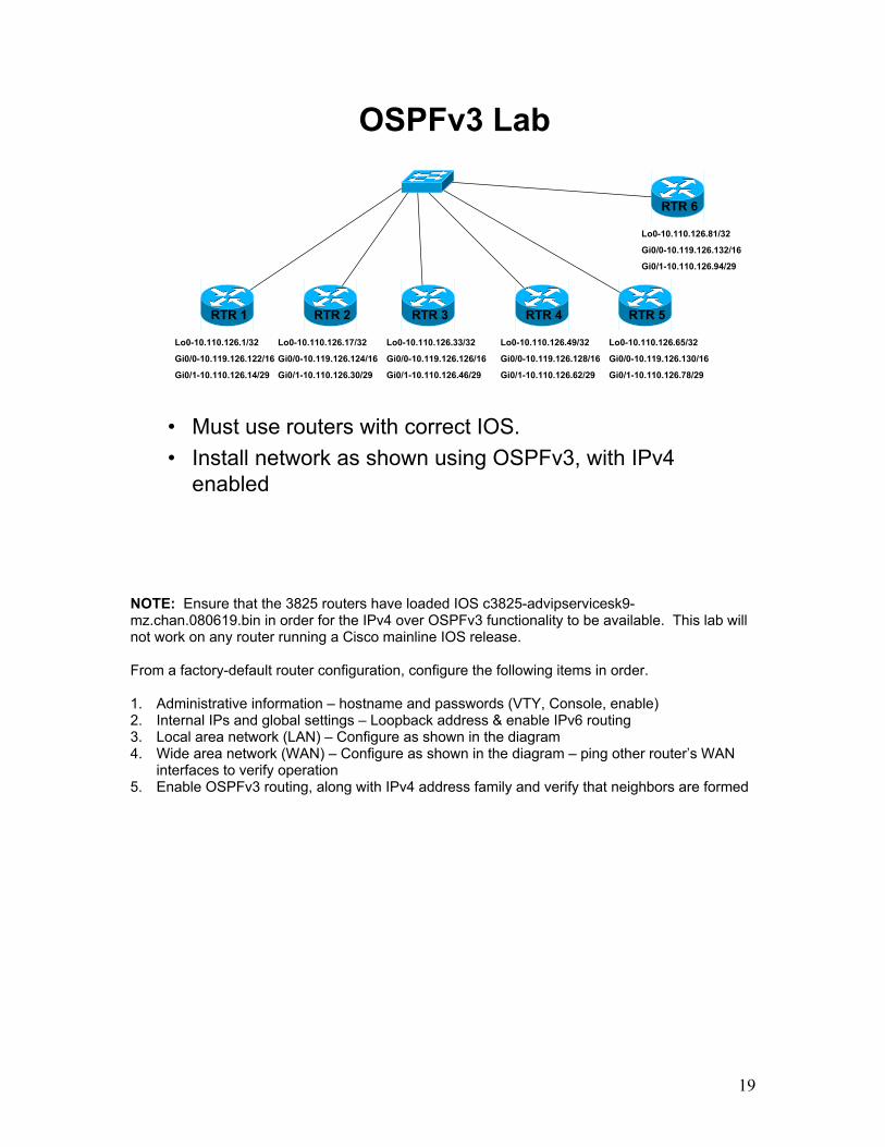
OSPFv3 Lab
• Must use routers with correct IOS.• Install network as shown using OSPFv3, with IPv4
enabled
RTR 1 RTR 2 RTR 3 RTR 4 RTR 5
Lo0-10.110.126.1/32
Gi0/0-10.119.126.122/16
Gi0/1-10.110.126.14/29
Lo0-10.110.126.17/32
Gi0/0-10.119.126.124/16
Gi0/1-10.110.126.30/29
Lo0-10.110.126.33/32
Gi0/0-10.119.126.126/16
Gi0/1-10.110.126.46/29
Lo0-10.110.126.49/32
Gi0/0-10.119.126.128/16
Gi0/1-10.110.126.62/29
Lo0-10.110.126.65/32
Gi0/0-10.119.126.130/16
Gi0/1-10.110.126.78/29
RTR 6
Lo0-10.110.126.81/32
Gi0/0-10.119.126.132/16
Gi0/1-10.110.126.94/29
NOTE: Ensure that the 3825 routers have loaded IOS c3825-advipservicesk9-mz.chan.080619.bin in order for the IPv4 over OSPFv3 functionality to be available. This lab will not work on any router running a Cisco mainline IOS release. From a factory-default router configuration, configure the following items in order. 1. Administrative information – hostname and passwords (VTY, Console, enable) 2. Internal IPs and global settings – Loopback address & enable IPv6 routing 3. Local area network (LAN) – Configure as shown in the diagram 4. Wide area network (WAN) – Configure as shown in the diagram – ping other router’s WAN
interfaces to verify operation 5. Enable OSPFv3 routing, along with IPv4 address family and verify that neighbors are formed

Insert Tab #3 Here
Dynamic Multi-Point Virtual Private Networks
DMVPN

2

3
JNN Network –Satellite Backbone
Hub Node
BN CPN BN CPN
STEP
Ku TDMA
Ku FDMA
(BCT)
(Battalion level unit)
JNN
(Div/Corps)
DISN/GIG
DISN/GIG(cable)
The JNN network utilizes a Ku Band commercial satellite network for the backbone interconnectivity of its systems. Both Time Division Multiple Access (TDMA) and Frequency Division Multiple Access (FDMA) are utilized. The JNN network architecture is composed of three primary elements: 1. Unit Hub Node (UHN) 2. Joint Network Node (JNN) 3. Battalion Command Post Node (Bn CPN) These systems provide communications support to the various elements within an Army Division. The UHN is located at the Division and/or the Corps element. It provides connectivity to the Defense Information Systems Network (DISN) and the Global Information Grid (GIG). The UHN utilizes both FDMA and TDMA satellite connectivity. The JNN is located at the Brigade Combat Team (BCT) element. It serves as both a distribution point for the various systems within the BCT and provides direct network services for the Brigade headquarter elements. The JNN can utilize both TDMA and FDMA satellite connectivity. It has a single FDMA link, which is usually reserved connectivity to the UHN. The Bn CPN provides direct network access to users within a Battalion element. It utilizes only TDMA satellite connectivity. It has permanent links to the UHN and/or JNN and can establish on demand connections to other CPNs within the BCT.

4
Why Satellite?
• Allows for beyond line of sight (BLOS) extension.
• Accessible from virtually anywhere on the battlefield.
• No need for extensive “link” planning for installation of ground systems at a new location.
• Scales well for maneuver units.
• Current ground equipment readily transportable.
The use of satellite communications by the JNN network allows for the installation and operation of a very flexible intra-network backbone for its users. Tactical line of sight radio systems are normally limited to a maximum range of approximately 40 miles. This limits the area on a battlefield that maneuver units can cover. With satellite, two systems can establish a radio link as long as they are within the earth “footprint” of the satellite coverage. This coverage can be rather large allowing systems to be hundreds of miles apart. LOS radio link installation requires extensive planning and engineering utilizing complex computer programs to provide a “profile”. It is not always possible to establish an LOS radio link between two locations. Whenever LOS radio systems are moved to a new location, this link planning must be conducted again prior to the installation of the new radio link. Satellite on the other hand requires initial link planning for the installation of radio links. Once this is done, systems can move almost anywhere within the footprint and reestablish the radio link. Additionally, there are very virtually no limits to establishing a satellite link as long as there is a clear line of sight path between the earth system and the satellite. With the flexibility noted above, satellite based systems serve well in meeting the needs of Army combat units. As changes occur on the battlefield and units are required to move, satellite based systems provide them the ability to rapidly terminate and reestablish communications in a minimal amount of time. The current satellite systems utilized with the JNN systems are mounted on a tactical two wheeled trailer pulled by a HMMWV. This makes the system readily transportable for tactical maneuver units.

5
FDMA
• Users xmit on one carrier frequency and receive on another.• 2 carriers per full duplex link (point to point).• Scales poorly - inefficient use of space segment.• Does not support ad hoc networking.• Dedicated bandwidth, not shared.• No delay for link connection.
TDMA
• Users share carrier(s) for both xmit and receive.• Additional carriers can be defined to support network growth.• Scales well – efficient use of valuable space resource.• Supports ad hoc networking well.• Bandwidth is a shared resource, not dedicated.• Slight delay in establishing link connection.
Space Segment Usage/Efficiency
* Space segment efficiency directly related to type of modulation/encoding used.
Provided by BCBL(G)
Frequency Division Multiple Access: FDMA is a traditional technique whereby earth stations transmit simultaneously on different pre-assigned frequencies, into a common satellite transponder. In addition, the FDMA carrier is allotted a certain amount of bandwidth. This carrier is constantly being transmitted to the satellite, processed by it, and retransmitted back to earth by it regardless of user traffic. Only the system assigned a certain transmit frequency can use the allocated bandwidth. Time Division Multiple Access: TDMA is a digital transmission technology that allows a number of users to access a single radio frequency (RF) carrier without interference by allocating unique time slots to each user within each carrier. The type utilized within JNTC-S is referred to as Multi-Frequency TDMA Demand Assigned Multiple Access. This allows for dynamic allocation of time slots based on user requirements and allows multiple carriers on the satellite within the TDMA network. This forms a “bandwidth pool” for the users.

6
FDMA/TDMA Satellite Payload-users present
• Above depicts two users communicating via a satellite link - TDMA or FDMA.• Spectrum analyzer display depicts the radio carrier used between the two systems.• The carrier has a center frequency plus a certain amount of bandwidth.• Amount of bandwidth is dependant upon data rate transfer.
The above diagram displays two ground based satellite systems with a radio link established between the two through a satellite. This could be an FDMA or TDMA link. There are two users communicating through this link with laptop computers. Depicted between the two systems is a display from a spectrum analyzer. The “hump” on the screen is a representation of the radio carrier being received by one of the satellite systems. The carrier has a center frequency and a certain amount of bandwidth being utilized on each side of this center frequency. The amount of bandwidth is determined by the data rate being transmitted by the earth systems.

7
• Above depicts two systems with no user data being transferred.• Satellite resource utilization remains unchanged on an FDMA link.• Carrier can only be utilized by systems with the pre-assigned frequency & bandwidth.• User activity or inactivity has no affect on satellite resource utilization.
FDMA Satellite Payload-no users present
The diagram now shows no user traffic being transmitted through the satellite radio link. From a satellite resource utilization standpoint, there would be no change on an FDMA link (as depicted by the spectrum analyzer display). FDMA systems have pre-assigned frequencies and pre-assigned bandwidth allocation; only the systems allocated these resources can utilize them. User activity or inactivity has no affect on satellite resource utilization.

8
• Above depicts two systems with no user data being transferred.• No satellite resources are utilized on a TDMA link.• Once user data transfer is complete, bandwidth is returned to a pool for use by
other systems.• Bandwidth is allocated on demand - based on user requirements.• User activity or inactivity has a direct affect on satellite resource utilization.
TDMA Satellite Payload-no users present
The diagram still shows no user traffic being transmitted through the satellite radio link. From a satellite resource utilization standpoint, there would be a change on a TDMA link (as depicted by the spectrum analyzer display). Resources on a TDMA satellite network are allocated based on user requirements. When users communicating through a TDMA satellite link have information to transfer, resources are allocated, a carrier (center frequency and bandwidth), to support the requirement. Once the transfer of this information is complete, the resources are returned to a pool for use by other systems as needed.
9
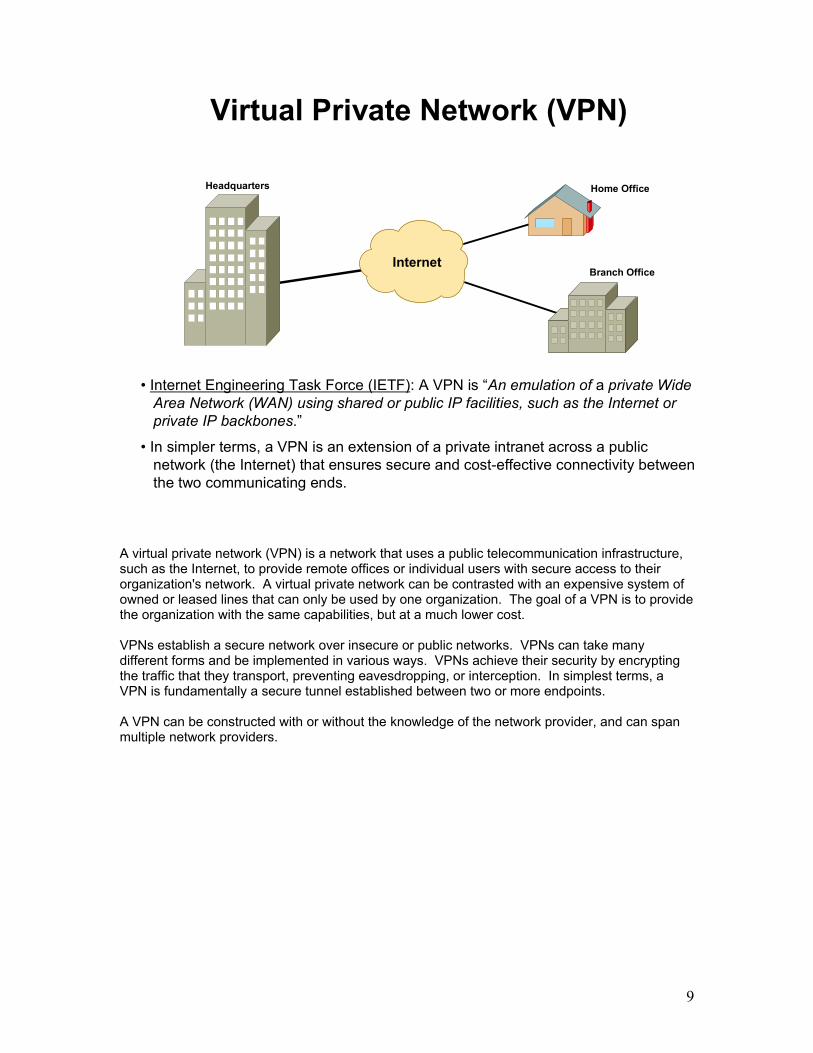
• Internet Engineering Task Force (IETF): A VPN is “An emulation of a private Wide Area Network (WAN) using shared or public IP facilities, such as the Internet orprivate IP backbones.”
• In simpler terms, a VPN is an extension of a private intranet across a publicnetwork (the Internet) that ensures secure and cost-effective connectivity between the two communicating ends.
Headquarters Home Office
Branch OfficeInternet
Virtual Private Network (VPN)
A virtual private network (VPN) is a network that uses a public telecommunication infrastructure, such as the Internet, to provide remote offices or individual users with secure access to their organization's network. A virtual private network can be contrasted with an expensive system of owned or leased lines that can only be used by one organization. The goal of a VPN is to provide the organization with the same capabilities, but at a much lower cost. VPNs establish a secure network over insecure or public networks. VPNs can take many different forms and be implemented in various ways. VPNs achieve their security by encrypting the traffic that they transport, preventing eavesdropping, or interception. In simplest terms, a VPN is fundamentally a secure tunnel established between two or more endpoints. A VPN can be constructed with or without the knowledge of the network provider, and can span multiple network providers.

10
Tunneling
Data TCP Hdr IP Hdr original IP packet
IP packet encapsulated w/tunnel protocol
• VPNs are established with the help of private logical tunnels. Tunneling is theencapsulation of one protocol within another.
• Tunnels enable the two ends to exchange data in a manner that resembles point-to-point communications.
• From a routing protocol stand point, the two routers depicted above would act asdirectly connected neighbors through the tunnel even though there may be several other routers physically between them.
TunnelTrailer
Data TCP Hdr
TunnelHdr
Orig IP Hdr
New IP Hdr
The VPNs are established with the help of private logical "tunnels." These tunnels enable the two ends to exchange data in a manner that resembles point-to-point communication. Tunneling technology lies at the core of VPNs. In addition, elaborate security measures and mechanisms can be used to ensure safe passage of sensitive data across an unsecured medium. Tunneling is the technique of encapsulating a data packet in a tunneling protocol, such as IP Security (IPSec), Point-to-Point Tunneling Protocol (PPTP), or Layer 2 Tunneling Protocol (L2TP), and then finally packaging the tunneled packet into an IP packet. The resultant packet is then routed to the destination network using the overlying IP information. Because the original data packet can be of any type, tunneling can support multi-protocol traffic, including IP, ISDN, FR, and ATM.

11
Tunnel Protocols
• Point-to-Point Tunneling Protocol (PPTP)
• Layer 2 Tunneling Protocol (L2TP)
• Internet Security Protocol (IPSec)*
• Generic Routing Encapsulation (GRE)
• Multi-point Generic Routing Encapsulation (mGRE)*
*utilized within the JNN network architecture
Point-to-Point Tunneling Protocol (PPTP) - Developed by Microsoft, 3COM, and Ascend Communications, PPTP was proposed as an alternative to IPSec. However, IPSec remains the favorite tunneling protocol. PPTP operates at layer 2 (Data Link layer) of the OSI model and is used for secure transmission of Windows-based traffic. Layer 2 Tunneling Protocol (L2TP) - Developed by Cisco Systems, L2TP was also intended to replace IPSec as the de facto tunneling protocol. However, IPSec continues to be the dominant protocol for secure communication over the Internet. L2TP is a combination of Layer 2 Forwarding (L2F) and PPTP and is used to encapsulate Point-to-Point Protocol (PPP) frames to be sent over X.25, FR, and ATM networks. IP Security (IPSec) - Developed by IETF, IPSec is an open standard that ensures transmission security and user authentication over public networks. Unlike other encryption techniques, IPSec operates at the Network layer of the seven-layer Open System Interconnect (OSI) model. Therefore, it can be implemented independently of the applications running over the network. As a result, the network can be secured without the need to implement and coordinate security for each individual application. Generic Routing Encapsulation (GRE) - A tunneling protocol developed by Cisco that can encapsulate a wide variety of protocol packet types inside IP tunnels, creating a virtual point-to-point link to Cisco routers at remote points over an IP inter-network. GRE allows routing updates to be sent over links that do not support broadcast and/or multicast. Multi-Point Generic Routing Encapsulation (mGRE) - mGRE allows a single GRE tunnel interface to support multiple tunnels (GRE is strictly point to point). This greatly simplifies the tunnel configuration and when used in conjunction with NHRP, tunnels can be established dynamically.

12
2.2.2.1/30s0/0s0/0
1.1.1.1/3012.12.12.0/24 11.11.11.0/24
.2 .2
UDPUDP IP HdrIP HdrPayloadPayload Tunn
IP HdrTunnIP Hdr
UDPUDP IP HdrIP
HdrPayloadPayload
GREGREs – 12.12.12.2d – 11.11.11.2
s – 12.12.12.2d – 11.11.11.2
UDPUDP IP HdrIP
HdrPayloadPayload
s – 12.12.12.2d – 11.11.11.2
s – 1.1.1.1d – 2.2.2.1
GRE Tunnel
• Routers 1 & 2 have a GRE tunnel established.
- host 12.12.12.2 sends a packet to host 11.11.11.2- router 1 encapsulates the packet with the IP’s assigned to serial interfaces.- router 2 de-encapsulates and delivers original packet.
• Packet is routed through the Internet based on the tunnel IP header.
1 2Internet
Generic Routing Encapsulation (GRE) is a Cisco proprietary (but published) standard for encapsulating routing protocols. It can encapsulate a wide variety of protocol packet types inside IP tunnels, creating a virtual point-to-point link to Cisco routers at remote points over an IP inter-network. By connecting multi-protocol sub-networks in a single-protocol backbone environment, IP tunneling that uses GRE allows network expansion across a single-protocol backbone environment. GRE, as specified in [RFC2784], is an IETF standard defining multi-protocol encapsulation format that could be suitable to tunnel any network layer protocol over any network layer protocol. GRE is normally used in two classes of applications: the transport of different protocols between IP networks and the provision of VPN services for networks configured with potentially overlapping private address space. The GRE header key field can be used to discriminate the identity of the customer network where encapsulated packets originate. In this way, it provides a way to offer many virtual interfaces to customer networks on a single GRE tunnel endpoint. This feature allows for policy-based routing (that is, when routing decisions are not based only on the destination IP address but on the combination of a virtual interface identifier, and the destination IP address) and relatively easy per-user network accounting. In addition, a GRE header allows the identification of the type of the protocol that is being carried over the GRE tunnel, thus allowing IP networks to serve as a bearer service onto which a virtual multi-protocol network can be defined and implemented. Similar to the IP in IP tunneling mechanism, the GRE tunneling technology does not include a tunnel setup protocol. It requires other protocols, such as Mobile IP, or network management to set up the tunnels. It also does not include security mechanisms and must be combined with IPSec to support secure user data delivery.

13
interface Tunnel0 creates a tunnel interface
ip address 10.10.10.1 255.255.255.252 assigns IP address & mask to tunnel
tunnel source Serial0/0 specifies which physical interface tunnel will utilize
tunnel destination 148.43.200.9 specifies the physical address associated with the distant end of the tunnel
GRE Tunnel Configuration
• GRE tunnels are point to point networks.
• GRE is the default tunnel encapsulation on a Cisco router.
• The physical IPs are used for encapsulating & routing the packet.
Above is the configuration commands utilized to establish a simple static GRE tunnel on a router. Once configured, the router treats the virtual tunnel interface the same as a physical interface. interface tunnel0: creates the tunnel interface; the tunnel can be designated with any number. NOTE: the three following commands are applied to the tunnel interface ip address: assigns an ip address and mask to the tunnel interface. tunnel source: specifies which physical interface on the router the tunnel interface will utilize to establish a connection to the distant end tunnel interface. tunnel destination: specifies the address of the physical interface the distant end tunnel interface is utilizing as its tunnel source. GRE IP is the default tunnel encapsulation on a Cisco router and therefore does not have to be configured.

14
GRE Tunnel Lab 1
interface Tunnel0ip address 10.10.10.1 255.255.255.252tunnel source Serial0/0tunnel destination 148.43.200.9
interface Tunnel0ip address 10.10.10.2 255.255.255.252tunnel source Serial0/0tunnel destination 148.43.200.10
148.43.200.9/30s0/0s0/0
148.43.200.10/3012.12.12.0/24 11.11.11.0/24
• Install the network as shown above.
• Enable EIGRP, configure network statements for tunnel & Ethernet interfaces.
• Once complete, ping from host computer to host computer.
In the above lab, establish a point-to-point router network. Then configure tunnel interfaces on each router utilizing the configuration examples above. Once the tunnel interfaces are installed, configure EIGRP with network statements for the tunnel interfaces and the Ethernet segments. Perform a ping test from a host on one Ethernet segment to a host the other. Examine the routing table of each router. What is the next hop address of the networks learned via EIGRP? The above diagram has a tunnel being established between two directly connected routers. It is possible to establish a tunnel between two routers with multiple routers in between. The two tunnel interfaces would act as if they are directly connected. It is a good practice to utilize different routing protocols on the tunnel and physical interfaces to prevent routing loops.

15
f0/0
GRE Tunnel Lab 2
f0/0
f0/0
f0/0
f0/0
f0/0
f0/0.193/28
.194/28
.195/28
.198/28
.197/28
.196/28.199/28
11.11.11.0/24
12.12.12.0/24
13.13.13.0/24
17.17.17.0/2414.14.14.0/24
15.15.15.0/24
16.16.16.0/24
1
2
3
4
5
6
7
The above is a broadcast multi-access network. The goal is to establish tunnels between all the systems. The following is a configuration example for router 1. Based on this example, as a group come up with an addressing & configuration scheme for each router within the tunneled network: Tunnel0 10.10.10.1/30, dest 148.43.200.194 Tunnel1 10.10.10.5/30, dest 148.43.200.195 Tunnel2 10.10.10.9/30, dest 148.43.200.196 Tunnel3 10.10.10.13/30, dest 148.43.200.197 Tunnel4 10.10.10.17/30, dest 148.43.200.198 Tunnel5 10.10.10.21/30, dest 148.43.200.199 How many subnets were created in this topology? By having all of these tunnels permanently in place, what affect would this have on the TDMA satellite network? If a router was added or removed from the topology, what would have to take place within the configurations? If time permits, install the above network within the classroom.

16
DMVPN
CommercialTDMA
Bn CPN Bn CPN
JNN
• DMVPN technology is utilized within the JNN network Architecture.
• Permanent VPNs are established between Hub/JNN & Bn CPN systems.
• Connections between CPN systems are established on an as needed basis utilizing DMVPN technology.
• TDMA satellite bandwidth is a shared resource; DMVPNs allow this to be utilized more efficiently.
The JNN network utilizes satellite radio links as the backbone to interconnect its IP based systems. There are two types of satellite networks within the JNN architecture: Time Division Multiple Access (TDMA) and Frequency Division Multiple Access (FDMA). For the past several years, legacy tactical communications systems have utilized FDMA satellite networks. Within FDMA, individual satellite systems are assigned a frequency and a certain amount of bandwidth. These two resources can then only be utilized by that system even if there is actually no user communications going through this link. TDMA on the other hand pools satellite bandwidth for use by ground systems on an as needed or demand basis. It is somewhat similar to a radio Ethernet network. For IP based systems to effectively utilize this TDMA network, dynamic multi-point virtual private networks (DMVPN) are established. IP Security (IPSec) is utilized to encrypt and authenticate the DMVPN traffic. DMVPN is composed of two protocols: multi-point generic routing encapsulation (mGRE) and next hop resolution protocol (NHRP). A DMVPN network is based on a hub/spoke topology. A system acts as the hub and all the others are considered spokes. Each spoke makes a permanent virtual connection to the hub. Initially, when a spoke system has traffic destined for another spoke system, it is routed through the hub. Utilizing NHRP, the hub provides the appropriate information so that a temporary virtual connection can be made between the two spoke systems. Essentially, connections are made on an as needed basis therefore effectively utilizing the satellite resources.

17
What is a DMVPN?
• DMVPNs allow the dynamic establishment of multiple GRE tunnelsthrough a single tunnel interface.
- based on a hub/spoke network design- tunnels can be established dynamically (as needed)- more efficiently utilizes network resources- minimizes router configuration size- allows routers to be added or removed from the topology without reconfiguring present routers
•Two protocols are utilized within DMVPNs.
- Multi-point GRE (mGRE)- Next Hop Resolution Protocol (NHRP)
The idea behind DMVPNs is that tunnels between certain routers can be established on an as needed basis. This has many benefits. The design is based on a hub/spoke topology with all spoke systems having a permanent tunnel to the hub system. Then as required the spoke systems dynamically establish tunnels between each other with information provided by the hub. This establishing of tunnels as needed and then terminating them once packet transfer is complete is very efficient in that network resources are only utilized when needed. Permanent VPNs (tunnels) utilize network resources even when there is no user traffic being transferred through the tunnel. When utilizing static tunnels with GRE, a separate tunnel interface and sub-net must be configured between the hub and each spoke. Depending on the number of routers involved, the size of the configuration and the numbers of IP’s required can be become quite extensive. DMVPNs by contrast have a simple configuration and the size of the configuration remains the same regardless of the number of routes participating. With DMVPNs as the network, topology changes (adding or removing routers) the configurations of the existing routers do not have to be modified. This makes the scaling of a DMVPN network very flexible. Static tunnels by contrast would require configuration changes to all routers within the network topology. To establish DMVPNs, three protocols are utilized: Multi-point GRE (mGRE), Next Hop Resolution Protocol (NHRP), and a dynamic routing protocol (OSPF or EIGRP).

18
Multi-Point Generic Router Encapsulation
• mGRE — allows a single GRE tunnel interface to support multiple tunnels.
• GRE tunnel configuration consists of:- ip address & mask- tunnel source- tunnel destination- optional tunnel key
• mGRE tunnel configuration consists of:- ip address & mask- tunnel source- tunnel key
• With mGRE, the tunnel destination is not defined.
• mGRE relies on NHRP to supply the tunnel destination information which it then utilizes to dynamically establish the tunnel.
Tunneling protocols such as IPSec can only support IP unicast traffic. Routing protocols such as OSPF and EIGRP exchange routing information via multi-cast therefore tunneling protocols such as IPSec cannot support dynamic routing. GRE was created to support multi-protocol traffic (IPX & AppleTalk) and in addition support all types of IP traffic (unicast, broadcast, & multicast). GRE however only supports point-to-point tunneling in which the source and destination addresses are specified. For each additional tunnel, a separate tunnel interface must be configured with the source and destination specified. mGRE, on the other hand, allows the establishment of multiple tunnels via a single tunnel interface. It is in a sense a broadcast multi-access tunnel interface. Within the mGRE configuration, only the source addressing information is supplied. The destination address is learned dynamically relying on some other protocol such as NHRP.

19
• Client/server protocol: hub is server & spokes are clients.
• Each client registers with server: tunnel address and associatedtunnel source interface address (physical).
• Server maintains an NHRP database of these registrations.
• Clients request next hop information (tunnel to physical addressresolution) from server to establish dynamic tunnel to anotherspoke.
Next Hop Resolution Protocol (NHRP)
Next Hop Resolution Protocol (NHRP) is a client/server protocol that provides the capability for the spoke routers to dynamically learn the exterior physical interface address of other spoke routers within the DMVP network. Spoke routers a considered the clients and the hub router is the server. NHRP is used by a source station (host or router) connected to a Non-Broadcast, Multi-Access (NBMA) subnetwork to determine the internetworking layer address and NBMA subnetwork addresses of the "NBMA next hop" towards a destination station. If the destination is connected to the NBMA subnetwork, then the NBMA next hop is the destination station itself. Otherwise, the NBMA next hop is the egress router from the NBMA subnetwork that is "nearest" to the destination station. NHRP is intended for use in a multiprotocol internetworking layer environment over NBMA subnetworks. NHRP Resolution Requests traverse one or more hops within an NBMA subnetwork before reaching the station that is expected to generate a response. Each station, including the source station, chooses a neighboring NHS to which it will forward the NHRP Resolution Request. The NHS selection procedure typically involves applying a destination protocol layer address to the protocol layer routing table, which causes a routing decision to be returned. This routing decision is then used to forward the NHRP Resolution Request to the downstream NHS. The destination protocol layer address previously mentioned is carried within the NHRP Resolution Request packet. Note that even though a protocol layer address was used to acquire a routing decision, NHRP packets are not encapsulated within a protocol layer header but rather are carried at the NBMA layer using the encapsulation described in its own header.

20
• Hub is the NHRP server, spokes are clients.• Clients register to server with address mapping information.• Server replies to clients once registration is complete.
NHRP (1)
tunnel 10.10.10.2/28f0/1 148.43.200.10/29
tunnel 10.10.10.3/28f0/1 148.43.200.20/29
tunnel 10.10.10.1/28f0/1 148.43.200.1/29
NHRPRegistration10.10.10.2 148.43.200.10
client 1
serverRegistration
ReplyNHRP
Registration10.10.10.3 148.43.200.20
client 2
TDMATDMA
NHRP Database10.10.10.2 148.43.200.1010.10.10.3 148.43.200.20
The registration request is sent from the client (spoke) to the server (hub) in order to identify or register its NHRP information. The destination protocol address field is set to the server’s IP address or address of the client in the event the client is not specifically configured with next hop server information. If the address field is set with the server’s address or with a client’s address that is within the same subnet as the server, then the server places the client NHRP information in its NHRP database. The server then sends a registration reply to the client informing it is now registered with this server. If the destination protocol address field is not set with the server’s address and the client IP is not within the same subnet as the server, then the server forwards the registration to another next hop server.

21
NHRPResolution
Request10.10.10.3
• Client 1 has packets destined for a network belonging to client 2.• Client 1 sends request to server for resolution of the next hop tunnel address to physical address of client 2.
NHRP Database10.10.10.2 148.43.200.1010.10.10.3 148.43.200.20
tunnel 10.10.10.2/28f0/1 148.43.200.10/29
tunnel 10.10.10.3/28f0/1 148.43.200.20/29
tunnel 10.10.10.1/28f0/1 148.43.200.1/29
TDMA TDMA
server
client 1 client 2
NHRP (2)
A resolution request is sent from a client to the server in order to identify the address for the next hop end point in the network. If the requested endpoint belongs to the server that has received the request, then it formulates a reply based on information contained in its database. Otherwise, the request must be forwarded to a next hop server that supports that endpoint. Within the JNN DMVPN network, the request contains the destination router’s tunnel address requesting the destinations associated physical address.

22
NHRPResolution
Reply10.10.10.3 148.43.200.20
• Server replies with the tunnel to physical address resolution.• Client 1 enters this into its NHRP database.
tunnel 10.10.10.2/28f0/1 148.43.200.10/29
tunnel 10.10.10.3/28f0/1 148.43.200.20/29
tunnel 10.10.10.1/28f0/1 148.43.200.1/29
TDMA TDMA
NHRP Database
10.10.10.3 148.43.200.20
client 1 client 2
server
NHRP (3)NHRP Database
10.10.10.2 148.43.200.1010.10.10.3 148.43.200.20
A resolution reply is sent from the server to requesting client. The reply provides a mapping of the requested destination tunnel address to the destination physical address. This information is then entered into the client’s NHRP database. This type of reply is termed an authoritative reply. The server that supports the subnet in question generates the reply. In the case where a resolution request was forwarded by an NHRP server to another server, it is possible for a server to receive a resolution reply. Once it has received the reply, it forwards it to the originating client. It also caches this reply for later use. When the same request is received again, it can use this cached information to reply instead of forwarding the request to the server that actually supports that subnet. This type of reply is termed non-authoritative.

23
dynamic tunnel
• Client 1 utilizes received NHRP info to establish a dynamic tunnel to client 2.• Tunnel will be terminated after a predetermined amount of time.
tunnel 10.10.10.2/28f0/1 148.43.200.10/29
tunnel 10.10.10.3/28f0/1 148.43.200.20/29
tunnel 10.10.10.1/28f0/1 148.43.200.1/29
TDMA TDMA
NHRP Database10.10.10.3 148.43.200.20
TDMAclient client
UDPUDP IP HdrIP HdrPayloadPayload Tunn
IP HdrTunnIP HdrGREGRE
s – 148.43.200.10d – 148.43.200.20
NHRP (4)NHRP Database
10.10.10.2 148.43.200.1010.10.10.3 148.43.200.20
server
Once the client (spoke) has received the reply from the server and has entered it into its NHRP database, it now has the required information to establish a dynamic tunnel to the other spoke. When configuring mGRE tunnels, the information supplied is the IP address & mask of the tunnel and the source physical interface to be utilized by the tunnel. In addition to packets utilizing the tunnel actually exiting the configured physical interface, the tunneled packet also utilizes the IP address assigned to the physical interface as its source address. NHRP is dynamically supplying the destination tunnel address. The tunnel will be terminated after a predetermined amount of time. By default, the tunnel will stay active for 120 minutes. This value can be changed within the tunnel configuration.

24
DMVPN and Routing Protocols
• For DMVPN to work properly, a routing protocol must be enabled on the tunnel interface.
• Spokes must advertise their supported networks to the hub& the hub must propagate these to all the other spokes.
• Advertisements received by a spoke router must have the subnets originating router listed as the next hop.
• The same routing protocol cannot be enabled on the tunnel & physical interfaces or recursive routing may occur.
For DMVPNs to work properly, a routing protocol must be utilized within the tunnel network so that the spokes can advertise their supported subnets to the hub. The hub then propagates these so that each spoke has knowledge of the subnets within the DMVPN topology. This is a key piece in the establishment of DMVPNs and can be easily overlooked. It is very common for a routing protocol to also be in operation on the physical network in addition to the tunnel network. It is very important that different routing protocols be utilized inside and outside of the tunnel to prevent recursive routing (routing loops). Recursive routing simply means that the routing table has found that the best path to the tunnel destination is through the tunnel. This means that the router cannot send the tunnel protocol’s TCP packets to the destination device because it thinks that they have to be encapsulated in the tunnel protocol again. This is a loop of sorts and the tunnel will be in a constant state of being torn down and rebuilt (up/down status). The other problem that can occur when using the same routing protocol inside and outside the tunnel is that packets can possibly be routed external to the tunnel. This can cause numerous problems and somewhat defeats the purpose of establishing the tunnel. Also, if IPSec is being applied to the tunnel, any packets that should be going through the tunnel but are routed externally will not have IPSec applied.

25
OSPF & EIGRP
• Certain configuration steps must be applied to the tunnel interfacewhen utilizing OSPF and EIGRP.
• OSPF- configure OSPF network type to broadcast (ip ospf network broadcast).- configure OSPF priority so hub is always DR (ip ospf priority).- insure the IP MTU is set the same on all tunnel interfaces (ip mtu).
• EIGRP- split horizons must be disabled on the hub (no ip split-horizons eigrp).- by default, eigrp routers list themselves as the next hop for all advertisedroutes – must be disabled (no ip next-hop-self eigrp).
- configure tunnel interface bandwidth so that EIGRP related traffic can beproperly maintained.
- consideration should also be given to configuring the spoke routers as EIGRP stub routers.
Depending on the routing protocol selected, there are certain configuration steps that must be taken for it to work properly within a DMVPN environment. OSPF: • OSPF considers a tunnel interface point to point, and will not allow it to support multiple
connections. Tunnel interface must be set to broadcast within OSPF. • Once interface is set to broadcast, OSPF treats it as part of a broadcast multi-access
network. The hub router must always be the designated router. A good practice would be to set the priority of all the spokes to “0”.
• Insure that all the ip mtu setting on the tunnel interfaces within the DMVPN topology are set
the same. Two OSPF routers cannot form a neighbor relationship if this setting is different. EIGRP: • Split horizons must be disabled on the hub tunnel interface (split horizons is enabled by
default with EIGRP). Since the hub is using a single interface to form connections with several spoke routers, EIGRP has to be able to send routing updates received from one to all other spokes. With split horizons enabled, this is not possible.
• By default, when an EIGRP router advertises a network, it lists itself as the next hop even if
the network does not originate on that router. For DMVPNs to function properly, this must be disabled on the hub router. Networks advertised from spokes to the hub and then to other spokes must list the originating spoke as the next hop.
• The default bandwidth for a tunnel interface is 9 kbs. EIGRP will only utilize at a maximum
half the interface bandwidth – 4.5 kbs. This is too low for EIGRP to be properly maintained between neighboring routers. Set the bandwidth to a higher value such as 1000.

26
• Consideration should be given to configuring the EIGRP routers as stub. By definition, the spokes should only have connections to one router, the hub. Therefore, there is no value added by allowing the hub to query the spokes.

27
• By default, OSPF treats a tunnel interface as a point to point network.• All tunnel interfaces on routers within a DMVPN net are on the same subnet.• OSPF must operate as if it is enabled on a broadcast multi-access network.• Tunnel interface must be set to broadcast for proper operation of the DMVPN.
OSPF & DMVPN –Broadcast Network
hub
spoke 1 spoke 2tunnel 10.10.10.2/28 - broadcastf0/1 148.43.200.10/29
tunnel 10.10.10.3/28 - broadcastf0/1 148.43.200.20/29
tunnel 10.10.10.1/28 - broadcastf0/1 148.43.200.1/29
TDMA TDMA
hub
spoke 1 spoke 2
OSPF considers a tunnel interface as a point-to-point network and will not allow it to support multiple OSPF neighbor connections. For DMVPNs to function properly, the tunnel interface must be set to OSPF broadcast. All tunnel interfaces belonging to routers within the same DMVPN network are configured as part of the same subnet. Configuring the tunnel interface to broadcast will cause all of these routers to function as part of the same OSPF broadcast multi-access network.

28
• Spoke routers have permanent connectivity only to the hub router.• Spoke routers will only form an OSPF neighbor relationship with the hub.• The hub must be elected as the OSPF designated router (DR).• Set all spoke routers' OSPF priority to 0.
OSPF & DMVPN - Hub is DR
TDMA TDMA
hub
spoke 1 spoke 2
tunnel 10.10.10.2/28 - priority 0f0/1 148.43.200.10/29
tunnel 10.10.10.3/28 - priority 0f0/1 148.43.200.20/29
tunnel 10.10.10.1/28 - priority 1f0/1 148.43.200.1/29
(DR)
(Drother) (Drother)
Once the DMVPN topology has been configured to function as an OSPF broadcast multi-access network, the OSPF priority must be configured for the designated router (DR) election. The goal is have the hub (NHRP server) always be the DR and the spokes (NHRP clients) never be the DR. To accomplish this, all spokes should have their OSPF priority configured as “0”. If there are going to be multiple hubs (servers) within a single DMVPN topology, the priority should be set according to which of these should be the DR and which should be the backup designated router (BDR).

29
• Within the JNN network, several tunnels along with IPSec are configured.• These functions add additional bytes to the packet.• To limit fragmentation, the MTU settings of the IP packets is reduced. • For two routers to form an OSPF neighbor relationship, the interfaces providing
connectivity for this must have the same IP MTU setting.
OSPF & DMVPN - IP MTU
TDMA TDMA
hub
spoke 1 spoke 2
tunnel 10.10.10.2/28 - ip mtu 1420f0/1 148.43.200.10/29
tunnel 10.10.10.3/28 - ip mtu 1420f0/1 148.43.200.20/29
tunnel 10.10.10.1/28 - ip mtu 1420f0/1 148.43.200.1/29
Within the JNN TDMA topology, several tunnels are created and IPSec is applied to these tunnels at various points. This tunnel creation and application of IPSec causes additional overhead to be added to the original IP packet causing the size (bytes) of the packet to increase. Ethernet based networks have a default maximum transmission unit (MTU) of 1500 bytes. Once the packet exceeds this size, packet fragmentation occurs. This can have detrimental effects on the processing of packets and can interfere with the operation of IPSec. To prevent the fragmentation of packets on the interface, the IP MTU size is adjusted on the tunnel interface. The actual setting can be calculated based on the additional overhead added by the above noted processes. For two routers to form an OSPF neighbor relationship, the interfaces being utilized by the routers must have the same MTU setting.

30
DMVPN Configuration - JNN
interface Tunnel7731bandwidth 2048ip address 172.21.16.233 255.255.255.0ip mtu 1289ip nhrp authentication 167731ip nhrp map multicast dynamicip nhrp map multicast 10.230.16.1ip nhrp map 172.21.16.20 10.230.16.1ip nhrp network-id 7731ip nhrp holdtime 600ip nhrp nhs 172.21.16.20ip tcp adjust-mss 1201ip ospf network broadcastip ospf cost 1100ip ospf priority 10tunnel source GigabitEthernet0/1tunnel mode gre multipointtunnel key 7731
interface tunnel 7731: Configures a tunnel interface. ip address: Assigns an IP address & mask to the tunnel interface. ip mtu: Sets the maximum transmission unit size on the tunnel interface. If an IP packet exceeds the MTU set for the interface, the Cisco IOS software will fragment it. All devices on a physical medium must have the same protocol MTU in order to operate. Within the DMVPN network, the MTU size for the tunnel interface is set to a smaller size than what is utilized for the physical interface (such as 1500 for Ethernet). This insures that once the packet is encapsulated with mGRE and IPSec that it will not exceed the physical MTU size and be fragmented once the additional headers & encryption have been applied. ip nhrp authentication: Configure the authentication string for an interface using the Next Hop Resolution Protocol (NHRP). All routers configured with NHRP within one logical NBMA network must share the same authentication string. ip nhrp map multicast dynamic: Configures NBMA addresses for use as destinations for broadcast or multicast packets to be sent over a tunnel network. When multiple NBMA addresses are configured, the system replicates the broadcast packet for each address. When utilized with the key word dynamic, multicast & broadcast packets are sent to all entries within the NHRP database. This is utilized on the hub so that router neighbor relationships can be established with all spoke systems dynamically. ip nhrp network-id: Enables the Next Hop Resolution Protocol (NHRP) on an interface. All NHRP stations within one logical NBMA network must be configured with the same network identifier.

31
ip nhrp holdtime: Changes the number of seconds that NHRP NBMA addresses are advertised as valid in authoritative NHRP responses. The command affects authoritative responses only. The advertised holding time is the length of time the Cisco IOS software tells other routers to keep information that it is providing in authoritative NHRP responses. The cached IP-to-NBMA address mapping entries are discarded after the holding time expires. The NHRP cache can contain static and dynamic entries. The static entries never expire. Dynamic entries expire regardless of whether they are authoritative or non-authoritative. Ip tcp adjust-mss: Adjusts the MSS value of TCP SYN packets going through a router. The max-segment-size argument is the maximum segment size, in bytes. The range is from 500 to 1460. Due to the multiple encapsulations that end packets use in a multi-tunnel network, this helps ensure that each communications endpoint never sends a TCP packet that will be fragmented. ip ospf network broadcast: Configures the OSPF network type to a type other than the default for a given medium. By default, the router sees a tunnel interface as part of a point-to-point network. By using the command and the key word broadcast, it causes OSPF to operate in a broadcast multi-access mode. ip ospf priority: Sets the OSPF router priority, which helps determine the designated router for a BMA network. When two routers attached to a network both attempt to become the designated router, the one with the higher router priority takes precedence. If there is a tie, the router with the higher router ID takes precedence. A router with a router priority set to zero is ineligible to become the designated router or backup designated router. In the DMVPN topology, the hub router should always be the designated router and the spokes never be the DR. tunnel source: Designates the router physical interface to be utilized as the source for this tunnel. Any traffic originating from the tunnel will be sent through the tunnel source interface. In addition, the IP address assigned to the tunnel source will be utilized as the source address of the tunneled packets. tunnel mode gre multipoint: Sets the tunnel encapsulation mode to gre multipoint. tunnel key: Enables an ID key for a tunnel interface. This command currently applies to (GRE) only. Tunnel ID keys can be used as a form of weak security to prevent improper configuration or injection of packets from a foreign source. When GRE is used, the ID key is carried in each packet. It is not recommended to be used for security purposes. All routers wishing to establish DMVPNs must have the same key. tunnel protection ipsec profile: Associates a tunnel interface with an IP Security (IPSec) profile. Use the command to specify that IPSec encryption will be performed after the GRE has been added to the tunnel packet. The tunnel protection command can be used with multipoint GRE (mGRE) and point-to-point GRE (p-pGRE) tunnels. With p-pGRE tunnels, the tunnel destination address will be used as the IPSec peer address. With mGRE tunnels, multiple IPSec peers are possible; the corresponding NHRP mapping NBMA destination addresses will be used as the IPSec peer addresses. If you wish to configure two Dynamic Multipoint VPN (DMVPN) mGRE and IPSec tunnels on the same router, you must issue the shared keyword.
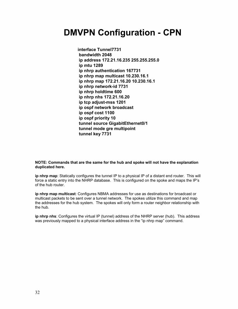
32
DMVPN Configuration - CPN
interface Tunnel7731bandwidth 2048ip address 172.21.16.235 255.255.255.0ip mtu 1289ip nhrp authentication 167731ip nhrp map multicast 10.230.16.1ip nhrp map 172.21.16.20 10.230.16.1ip nhrp network-id 7731ip nhrp holdtime 600ip nhrp nhs 172.21.16.20ip tcp adjust-mss 1201ip ospf network broadcastip ospf cost 1100ip ospf priority 10tunnel source GigabitEthernet0/1tunnel mode gre multipointtunnel key 7731
NOTE: Commands that are the same for the hub and spoke will not have the explanation duplicated here. ip nhrp map: Statically configures the tunnel IP to a physical IP of a distant end router. This will force a static entry into the NHRP database. This is configured on the spoke and maps the IP’s of the hub router. ip nhrp map multicast: Configures NBMA addresses for use as destinations for broadcast or multicast packets to be sent over a tunnel network. The spokes utilize this command and map the addresses for the hub system. The spokes will only form a router neighbor relationship with the hub. ip nhrp nhs: Configures the virtual IP (tunnel) address of the NHRP server (hub). This address was previously mapped to a physical interface address in the “ip nhrp map” command.
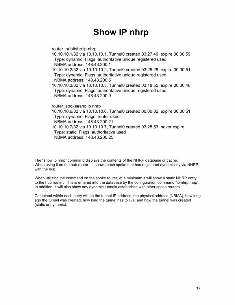
33
router_hub#sho ip nhrp10.10.10.1/32 via 10.10.10.1, Tunnel0 created 03:27:40, expire 00:00:59
Type: dynamic, Flags: authoritative unique registered usedNBMA address: 148.43.200.1
10.10.10.2/32 via 10.10.10.2, Tunnel0 created 03:25:28, expire 00:00:51Type: dynamic, Flags: authoritative unique registered usedNBMA address: 148.43.200.5
10.10.10.3/32 via 10.10.10.3, Tunnel0 created 03:18:55, expire 00:00:46Type: dynamic, Flags: authoritative unique registered usedNBMA address: 148.43.200.9
router_spoke#sho ip nhrp10.10.10.6/32 via 10.10.10.6, Tunnel0 created 00:00:02, expire 00:00:51
Type: dynamic, Flags: router usedNBMA address: 148.43.200.21
10.10.10.7/32 via 10.10.10.7, Tunnel0 created 03:28:53, never expireType: static, Flags: authoritative usedNBMA address: 148.43.200.25
Show IP nhrp
The “show ip nhrp” command displays the contents of the NHRP database or cache. When using it on the hub router. It shows each spoke that has registered dynamically via NHRP with the hub. When utilizing the command on the spoke router, at a minimum it will show a static NHRP entry to the hub router. This is entered into the database by the configuration command “ip nhrp map”. In addition, it will also show any dynamic tunnels established with other spoke routers. Contained within each entry will be the tunnel IP address, the physical address (NBMA), how long ago the tunnel was created, how long the tunnel has to live, and how the tunnel was created (static or dynamic).

34
Show IP NHRP NHS
router_spoke#sh ip nhrp nhs
Legend:E=Expecting repliesR=Responding
Tunnel6600:172.21.254.1 RE
The “show ip nhrp nhs” command displays a spoke router’s communications status with its configured next hop server(s). When successfully registered and active, the status codes R & E will both be present. Once an NHS address is configured within a Tunnel interface via the “ip nhrp nhs” command, it will be listed with this command, whether the address is correct or not. The “E” status code will always appear with this command whether the configuration is correct or not. If the “R” status code is missing, it is recommended to verify that the physical address that the NHS server is mapped to is reachable via the ping command. Refer to the tunnel configuration and check the entry for “ip nhrp map <nhs_ip> <phys_ip>. Verify that the addresses are in the correct order. Once connectivity and configuration are verified, restart the NHRP registration process by performing a “shut” and “no shut” on the tunnel interface.

35
TDMA TDMA
JNN JNN
Bn CPN
Bn CPN Bn CPN
Bn CPN
FDMA serial
FDMA serial
FDMA serial
Ethernet
Ethernet
Ethernet
Ethernet
Ethernet
Ethernet
Ethernet
Ethernet
BCT 1 BCT 2
HubUHN_66030_ST2R
LO0 22.230.0.6/32
FA0/0 172.20.254.1/29
TU6605 172.21.78.1/25
TU6607 172.21.79.1/25
VLAN 59 22.230.3.254/24
DMAIN – OSPF Area 0
22.230.0.0/19
OSPF Area 0
22.230.32.0/19
JNN_66050_ST2R
LO0 22.230.32.2/32
FA0/0 172.20.78.9/29
TU6605 172.21.78.8/25
VLAN 59 22.230.34.62/27
BCP_66052_ST2R
LO0 22.230.32.9/32
FA0/0 172.20.78.17/29
TU6605 172.21.78.16/25
VLAN 59 22.230.40.62/27
BCP_66053_ST2R
LO0 22.230.32.10/32
FA0/0 172.20.78.25/29
TU6605 172.21.78.24/25
VLAN 59 22.230.44.62/27
UA 2 – OSPF Area 0
22.230.64.0/19
BCP_66072_ST2R
LO0 22.230.64.9/32
FA0/0 172.20.79.17/29
TU6607 172.21.79.16/25
VLAN 59 22.230.72.62/27
BCP_66073_ST2R
LO0 22.230.64.10/32
FA0/0 172.20.79.25/29
TU6607 172.21.79.24/25
VLAN 59 22.230.76.62/27
JNN_66070_ST2R
LO0 22.230.64.2/32
FA0/0 172.20.79.9/29
TU6607 172.21.79.8/25
VLAN 59 22.230.66.62/27
Install the above network as shown. Configure the hub and spoke routers using the configuration information from the two previous pages. Enable OSPF to operate on the tunnel interface and the interface supporting host computers. Do not configure a routing protocol for the physical interfaces connected to the TDMA cloud. Configure a static route. The TDMA router’s Ethernet interface is configured with all seven physical subnets. Configure the first subnet with “ip address” command and then the other six with “ip address” command and the “secondary” extension. Once complete, test for network connectivity using ping and trace between the user subnets. Utilize the “show ip nhrp” command to view the tunnels in place.

Insert Tab #4 Here

Multicast

2

3
What is Multicast?
• A one-to-many packet distribution scheme
IP multicast routing enables a host (source) to send packets to a group of hosts (receivers) anywhere within the IP network by using a special form of IP address called the IP multicast group address. The sending host inserts the multicast group address into the IP destination address field of the packet and IP multicast routers and multilayer switches forward incoming IP multicast packets out all interfaces that lead to the members of the multicast group. Any host, regardless of whether it is a member of a group, can send to a group. However, only the members of a group receive the message. With Unicast, traffic one copy of a packet goes to each client so if there is a large group of clients a large number of the same packets take up bandwidth on the same network, particularly if the traffic is multimedia. Although this may sometimes be called 'Multicast', it is in fact 'Replicated Unicast'. A single video stream between a client and a server takes about 1.5Mbps of bandwidth. With broadcasts, only one copy of a packet is sent to all clients but each client has to process the broadcast packet even if the packet is not relevant to them. Routers do not forward layer 2 broadcasts, so 'Directed IP Broadcasts‘ would have to be used. Routers DO forward multicast packets. Because multimedia traffic is large in volume, it is impractical to expect all clients to look at all the multimedia broadcast packets. Multicast techniques use special multicast addresses that groups of clients can choose to listen to or ignore. This way we get the best of both worlds whereby only those clients that choose to be part of the group get to process the data. This group is identified by a single multicast IP address, the server does not know individual IP addresses so the clients remain anonymous. Multicast traffic is handled by UDP at the transport layer.

4
Tactical Multicast Applications
• TACLANE SDD• Multipoint Conferencing• GBS – Global Broadcast System• CPOF – Command Post of the Future
The concept of multicast originated during the 1980s at Stanford University. A doctoral graduate student was working on a distributed Operating System called Vsystem, which consisted of several loosely coupled computers together via a single Ethernet segment. They communicated via a primitive MAC-based multicast process in order to exchange operating system level messages. As the program grew, the need arose to add more computers to the network; however, there was no more space in the local area for additional hardware. The computers were added to the other side of the campus, requiring the engineers to come up with a means of extending their protocols to work across the now Layer 3 network. The protocols developed became the basis for the multicast implementation used today, namely Internet Group Membership Protocol (IGMP) and Protocol Independent Multicast (PIM). While multicast was developed for a specific need at the time, the groundwork was laid in such a way that many different applications could take advantage of the same concept. It was quickly realized that this could be an efficient means of sharing voice and video, as well as distributing common files to multiple nodes simultaneously. Today the military makes extensive use of the multicast protocol for applications that require collaboration between many different locations using bandwidth-efficient means of distribution. The Warfighter Information Network – Tactical (WIN-T) enables multicast in order to form its TDMA links over the TACLANCE inline network encryptor. The Secure Dynamic Discovery (SDD) protocol it uses to form security associations utilizes the multicast protocol. The Global Broadcast System makes use of multicast to share live feeds of news channels and Unmanned Aerial Vehicle feeds from a downlink source to the local tactical network. Command Post of the Future utilizes multicast to distribute messages between CPOF sites across the battlefield. Commanders frequently use Video Teleconferencing (VTC) equipment over multicast to synchronize plans and ensure that progress is being made.

5
Benefits of Multicast
• Optimized network performance• Support for distributed applications• Resource economy• Scalability• More network availability
There are several benefits that multicast can bring to both highspeed local area networks, as well as lower bandwidth wide area networks including: Optimized network performance: The intelligent use of network resources avoids unnecessary flow replication. This way, an economy in terms of passing band is achieved through a better architecture to distribute the data. Support to distributed applications: Multicast technology is directed towards distributed applications. Multimedia applications such as distance learning and videoconference can be used in the network in a measurable and effective way. Resource economy: The cost of the network resources is reduced through the passing band economy in the links and the processing economy in servers and network equipment. New applications and services can be implanted, without requiring the renovation of network resources. Scalability: The effective use of the network and the reduction of the load in traffic sources, permit services and applications to be accessed by a great number of participants. Consequently, services that run on multicast can be easily dimensioned, distributing packages to both few and many receivers. More network availability: The economy of network resources associated to the reduction of the load in the applications and servers makes the network less susceptible to jams, and, therefore, more available to be used.

6
Disadvantages
• Multicast must be enabled on all routers –complexity
• Forwarding devices must replicate packets • Unreliable packet delivery (UDP-based)• Network congestion avoidance lacking• Out of sequence packets• Duplicate packet reception
It is also important to keep in mind when designing and implementing a multicast network to some of its inherent drawbacks: Configuration Complexity – While it is relatively simple to enable multicast at the local level, implementing into a large-scale network properly requires a great deal of network planning and configuration. Best Effort Delivery - Drops in the data stream are to be expected. Multicast applications should not expect reliable delivery of data and should be designed accordingly. Reliable multicast is in development. Requesting retransmissions of the lost data is not feasible due to the design of multicasting. Routers Must Replicate Packets – Most network devices responsible for forwarding multicast traffic through the network are routers. As such, their primary duty is to receive packets, make routing decisions, and switch packets to the correct outgoing interface. Multicast adds an additional strain to a router’s load in that not only does it need to make forwarding decisions, but also replicate all packets into every outgoing interface buffer that is required. No Congestion Avoidance - Unlike TCP, there are no windowing and 'slow-start' mechanisms. This can result in network congestion. If possible, Mulicast applications should attempt to detect and avoid congestion conditions. Duplication - Some multicast protocol mechanisms (Asserts, Registers, and Shortest Path Tree Transitions) may result in the occasional generation of duplicate packets. Multicast applications should be designed to take this into consideration. Out of Sequency Packets - Various network events may result in packets arriving out of sequence - as there is no windowing, multicast applications should handle these cases.

7
Multicast Addressing
• Class D Space 224.0.0.0 – 239.255.255.255– 224.0.0.0 – 224.0.0.255 – Link-local only– 224.0.1.0 – 238.255.255.255 – Global Addressing– 239.0.0.0 – 239.255.255.255 – Site local (Private)
• Layer 2 Addressing – Generated MAC based on Layer 3 Group Address– Begins with vendor code 0100.5exx.xxxx– Alleviates need for ARP for MAC to IP translation
IP multicast addresses have been assigned to the IPv4 Class D address space by IANA. The high-order four bits of a Class D address are 1110. Therefore, host group addresses can be in the range 224.0.0.0 to 239.255.255.255. A multicast address is chosen at the source (sender) for the receivers in a multicast group. Reserved Link-Local Addresses: The IANA has reserved the range 224.0.0.0 to 224.0.0.255 for use by network protocols on a local network segment. Packets with an address in this range are local in scope and are not forwarded by IP routers. Packets with link local destination addresses are typically sent with a time-to-live (TTL) value of 1 and are not forwarded by a router. Globally Scoped Addresses: Addresses in the range 224.0.1.0 to 238.255.255.255 are called globally scoped addresses. These addresses are used to send multicast data between organizations across the Internet. Some of these addresses have been reserved by IANA for use by multicast applications. Limited Scope Addresses: The range 239.0.0.0 to 239.255.255.255 is reserved as administratively or limited scoped addresses for use in private multicast domains. These addresses are constrained to a local group or organization. Companies, universities, and other organizations can use limited scope addresses to have local multicast applications that will not be forwarded outside their domain. Routers typically are configured with filters to prevent multicast traffic in this address range from flowing outside an autonomous system (AS) or any user-defined domain.

8
Layer 2 Addressing Historically, network interface cards (NICs) on a LAN segment could receive only packets destined for their burned-in MAC address or the broadcast MAC address. In IP multicast, several hosts need to be able to receive a single data stream with a common destination MAC address. Some means had to be devised so that multiple hosts could receive the same packet and still be able to differentiate between several multicast groups. One method to accomplish this is to map IP multicast Class D addresses directly to a MAC address. Using this method, NICs can receive packets destined to many different MAC address.

9
Layer 2 Addressing
1 1 1 0
0 1 2 3 4 5 6 7 8 9 15 16 23 24 31BitsClass D IP address
224 UnusedThese low order 23 bits are copied to the Ethernet address
Hex 01 00 5E
0000 0001 0000 0000 0101 1110 0
26 48
Ethernet multicast address
When possible, IP makes use of the multicast addressing and delivery capabilities of the underlying network to deliver multicast datagrams on a physical network. Multicast address resolution is done using a version of the direct mapping technique. By defining a mapping between IP multicast groups and data link layer multicast groups, we enable physical devices to know when to pay attention to multicasted datagrams. The most commonly used multicast-capable data link-addressing scheme is the IEEE 802 addressing scheme best known for it use in Ethernet networks. These data link layer addresses have 48 bits, arranged into two blocks of 24. The upper 24 bits are arranged into a block called the organizationally unique identifier (OUI), with different values assigned to individual organizations; the lower 24 bits are then used for specific devices. The Internet Assigned Numbering Authority (IANA) itself has an OUI that it uses for mapping multicast addresses to IEEE 802 addresses. This OUI is "01:00:5E". To form a mapping for Ethernet, 24 bits are used for this OUI and the 25th (of the 48) is always zero. This leaves 23 bits of the original 48 to encode the multicast address. To do the mapping, the lower-order 23 bits of the multicast address are used as the last 23 bits of the Ethernet address starting with "01:00:5E" for sending the multicast message. IP multicast addresses consist of the bit string “1110” followed by a 28-bit multicast group address. To create a 48-bit multicast IEEE 802 (Ethernet) address, the top 24 bits are filled in with the IANA’s multicast OUI, 01-00-5E, the 25th bit is zero, and the bottom 23 bits of the multicast group are put into the bottom 23 bits of the MAC address. This leaves 5 bits (shown in pink) that are not mapped to the MAC address, meaning that 32 different IP addresses may have the same mapped multicast MAC address.

10
Addressing Example
230.115.97.1
230 115 97 111100110 0111 0011 0110 0001 0000 0001
0100.5E 73.6101
Class D IP address
Ethernet multicast address
The above example demonstrates the mapping of an IPv4 multicast address to a 48 bit MAC address. It is important to note that the resulting MAC address, due to the 5 bit ambiguity inherent in the mapping scheme means that there are 31 additional multicast group addresses that can map into the same MAC address. Using the above example, those addresses would be 224.115.97.1, 224.243.97.1, 225.115.97.1, and so on to 239.243.97.1. This of little consequence in most cases because the scenario would require separate receivers of the above addresses to reside on the same LAN in order for them to both receive all traffic for both groups.

11
Key Terms & Protocols
• IGMP – Internet Group Membership Protocol • Multicast Distribution Trees (Source & Shared)• RPF - Reverse Path Forwarding• PIM – Protocol Independent Multicast• RP – Rendezvous Point• BSR – Bootstrap Router
Internet Group Membership Protocol – A protocol used by IP hosts and gateways to report their multicast group memberships. It is used in concert with a multicast protocol for IP based multicasting. Multicast Distribution Trees • Source – The root is the source of the multicast traffic and branches out to form a spanning
tree through the network to the receiver. A source tree uses the shortest path through the network and is known as the Shortest Path Tree (SPT).
• Shared – The root is not necessary the source of the multicast traffic. The root is considered a single common root and can be placed at some chosen point in the network. This root will be called the rendezvous point for Protocol Independent Multicast (PIM).
Reverse Path Forwarding – It is used to avoid multicast loops. A router will ensure the received packet entered from the most reliable reverse path to the source. If so, the packet is forwarded; if not, the packet is discarded. Protocol Independent Multicast – PIM is IP routing protocol independent in that is uses a current unicast routing table to perform RPF, no matter what protocol was used to populate the unicast table. Rendezvous Point – The single common root used in a Shared Multicast Distribution Tree. Bootstrap Router – It is introduced with PIMv2. BSR is another name for Rendezvous Point but used in an open standard network.

12
IGMPv2
Video Stream
Multicast Routing - IGMP
Video Server (Source)
End Station
4
3
2
51
3
Internet Group Management Protocol is used primarily by multicast hosts to notify their local router of their desire to join or leave a specific multicast group and to have traffic forwarded on to them. Using this information, a multicast router can maintain a list of multicast groups and the interfaces that have at least one member requesting traffic for it. An example of this process is described below. 1. The client sends an IGMP join message to its designated multicast router. The destination MAC address maps to the Class D address of the group being joined, rather than being the MAC address of the router. The body of the IGMP datagram also includes the Class D group address. 2. The router logs the join message and uses PIM or another multicast routing protocol to add this segment to the multicast distribution tree. 3. IP multicast traffic transmitted from the server is now distributed via the designated router to the client's subnet. The destination MAC address corresponds to the Class D address of group 4. The switch receives the multicast packet and examines its forwarding table. If no entry exists for the MAC address, the packet will be flooded to all ports within the broadcast domain. If an entry does exist in the switch table, the packet will be forwarded only to the designated ports. 5. With IGMP V2, the client can cease group membership by sending an IGMP leave to the router. With IGMP V1, the client remains a member of the group until it fails to send a join message in response to a query from the router. Multicast routers also periodically send an IGMP query to the "all multicast hosts" group or to a specific multicast group on the subnet to determine which groups are still active within the subnet. Each host delays its response to a query by a small random period and will then respond only if no other host in the group has already reported. This mechanism prevents many hosts from congesting the network with simultaneous reports.

13
Characteristics of Distribution Trees
• Source or Shortest Path trees– Uses more memory O(S x G) but you get optimal paths from
source to all receivers; minimizes delay
• Shared trees– Uses less memory O(G) but you may get sub-optimal paths
from source to all receivers; may introduce extra delay
Source or Shortest Path Tree Characteristics – Provides optimal path (shortest distance and minimized delay) from source to all receivers, but requires more memory to maintain. Shared Tree Characteristics – Provides sub-optimal path (may not be shortest distance and may introduce extra delay) from source to all receivers, but requires less memory to maintain.

14
Shortest Path Distribution Tree
Source 1Notation: (S, G)
S = SourceG = Group
Source 2
Receiver 1 Receiver 2
A B
C E
D F
Shortest Path Trees — aka Source Trees • A Shortest path or source distribution tree is a minimal spanning tree with the lowest cost
from the source to all leaves of the tree. • We forward packets on the Shortest Path Tree according to both the Source Address that the
packets originated from and the Group address G that the packets are addressed to. For this reason we refer to the forwarding state on the SPT by the notation (S,G) (pronounced “S comma G”) where:
o “S” is the IP address of the source. o “G” is the multicast group address
Example 1: The shortest path between Source 1 and Receiver 1 is via Routers A and C, and shortest path to Receiver 2 is one additional hop via Router E.

15
Shared Distribution Tree
Source 1Notation: (*, G)
* = All SourcesG = Group
Source 2
Receiver 1 Receiver 2
A B
C E
D F
(RP) PIM Rendezvous Point
Shared Tree
Source Tree
Shared Distribution Trees (cont.) • Before traffic can be sent down the Shared Tree, it must somehow be sent to the Root of the
Tree. • In classic PIM-SM, this is accomplished by the RP joining the Shortest Path Tree back to
each source so that the traffic can flow to the RP and from there down the shared tree. In order to trigger the RP to take this action, it must somehow be notified when a source goes active in the network.
• In PIM -SM, this is accomplished by first-hop routers (i.e. the router directly connected to an
active source) sending a special Register message to the RP to inform it of the active source. • In the example above, the RP has been informed of Sources 1 and 2 being active and has
subsequently joined the SPT to these sources.

16
Multicast Routing
• Multicast Routing is backwards from Unicast Routing– Unicast Routing is concerned about where the packet is going.– Multicast Routing is concerned about where the packet came
from.
• Multicast Routing uses “Reverse Path Forwarding”
Multicast Routing • Routers must know packet origin, rather than destination (opposite of unicast)
o origination IP address denotes known source o destination IP address denotes unknown group of receivers
• Multicast routing utilizes Reverse Path Forwarding (RPF)
o Broadcast: floods packets out all interfaces except incoming from source; initially assuming every host on network is part of multicast group
o Prune: eliminates tree branches without multicast group members; cuts off transmission to LANs without interested receivers
o Selective Forwarding: requires its own integrated unicast routing protocol
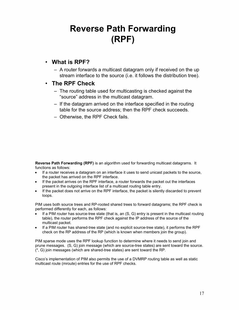
17
Reverse Path Forwarding (RPF)
• What is RPF?– A router forwards a multicast datagram only if received on the up
stream interface to the source (i.e. it follows the distribution tree).
• The RPF Check– The routing table used for multicasting is checked against the
“source” address in the multicast datagram.– If the datagram arrived on the interface specified in the routing
table for the source address; then the RPF check succeeds.– Otherwise, the RPF Check fails.
Reverse Path Forwarding (RPF) is an algorithm used for forwarding multicast datagrams. It functions as follows: • If a router receives a datagram on an interface it uses to send unicast packets to the source,
the packet has arrived on the RPF interface. • If the packet arrives on the RPF interface, a router forwards the packet out the interfaces
present in the outgoing interface list of a multicast routing table entry. • If the packet does not arrive on the RPF interface, the packet is silently discarded to prevent
loops. PIM uses both source trees and RP-rooted shared trees to forward datagrams; the RPF check is performed differently for each, as follows: • If a PIM router has source-tree state (that is, an (S, G) entry is present in the multicast routing
table), the router performs the RPF check against the IP address of the source of the multicast packet.
• If a PIM router has shared-tree state (and no explicit source-tree state), it performs the RPF check on the RP address of the RP (which is known when members join the group).
PIM sparse mode uses the RPF lookup function to determine where it needs to send join and prune messages. (S, G) join message (which are source-tree states) are sent toward the source. (*, G) join messages (which are shared-tree states) are sent toward the RP. Cisco’s implementation of PIM also permits the use of a DVMRP routing table as well as static multicast route (mroute) entries for the use of RPF checks.

18
Types of PIM
• Dense-mode– Uses “Push” Model– Traffic flooded throughout network– Pruned back where it is unwanted– Flood & Prune behavior (typically every 3 minutes)
• Sparse-mode– Uses “Pull” Model– Traffic sent only to where it is requested– Explicit Join behavior
Dense-mode multicast protocols • Initially flood/broadcast multicast data to entire network, then prune back paths that do
not have interested receivers. • A typical dense network is one with a large amount of available bandwidth and a large
number of hosts expected, such as a local area network or campus network. Sparse-mode multicast protocols
• Assumes no receivers are interested unless they explicitly ask for it. • WAN-based multicast would be an example of sparse – lower bandwidth with fewer
upstream connections and a smaller distribution tree. • Flooding will cause problems so more selective techniques are used to create the trees.
The trees start empty of any branches until there are explicit requests to join the distribution tree i.e. no packets are sent unless specifically asked for them.

19
PIM-DM
• Protocol Independent– Supports all underlying unicast routing protocols
including: static, RIP, IGRP, EIGRP, IS-IS, BGP, and OSPF
• Uses reverse path forwarding– Floods all network and prunes back based on
multicast group membership– Asset mechanism used to prune off redundant flows
• Appropriate for…– Smaller implementations and pilot networks
Protocol Independent Multicast (PIM) Dense-mode (Internet-draft) • Uses Reverse Path Forwarding (RPF) to flood the network with multicast data, then
prune back paths based on messages notifying routers that there are no interested receivers on a given segment.
• Interoperates with DVMRP – works along the same lines as this protocol, but does not require an underlying unicast routing mechanism.
Appropriate for small implementations and pilot networks
• Because of the flooding nature of the dense mode protocol, it is only appropriate to use this in a smaller network, generally controlled by one organization (autonomous system).
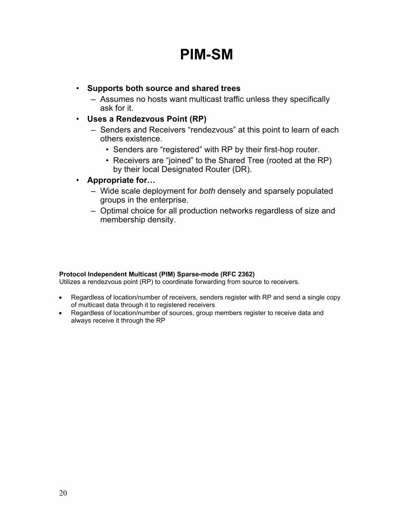
20
PIM-SM
• Supports both source and shared trees– Assumes no hosts want multicast traffic unless they specifically
ask for it.• Uses a Rendezvous Point (RP)
– Senders and Receivers “rendezvous” at this point to learn of each others existence.
• Senders are “registered” with RP by their first-hop router.• Receivers are “joined” to the Shared Tree (rooted at the RP)
by their local Designated Router (DR).• Appropriate for…
– Wide scale deployment for both densely and sparsely populated groups in the enterprise.
– Optimal choice for all production networks regardless of size and membership density.
Protocol Independent Multicast (PIM) Sparse-mode (RFC 2362) Utilizes a rendezvous point (RP) to coordinate forwarding from source to receivers.
• Regardless of location/number of receivers, senders register with RP and send a single copy
of multicast data through it to registered receivers • Regardless of location/number of sources, group members register to receive data and
always receive it through the RP

21
PIM-SM Shared Tree Joins
(*, G) JoinsShared Tree
(*, G) State created only along the Shared Tree
RP
PIM-SM Shared Tree Joins • In this example, there is an active receiver (attached to leaf router at the bottom of the
drawing) has joined multicast group “G”. • The leaf router knows the IP address of the Rendezvous Point (RP) for group G and when it
sends a (*,G) Join for this group towards the RP. • This (*, G) Join travels hop-by-hop to the RP building a branch of the Shared Tree that
extends from the RP to the last-hop router directly connected to the receiver. • At this point, group “G” traffic can flow down the Shared Tree to the receiver.

22
Configuring Multicast
Router (config) #ip multicast-routing • Enables multicast routing globally
Router (config-int) #ip pim sparse-dense-mode • Enables multicast on a per interface basis• Interface operates in dense mode until RP is selected
Enabling basic multicast functionality on a Cisco router is quite simple. The command ip multicast-routing is used to enable multicast globally. If you configure either the ip pim sparse-mode or ip pim dense-mode interface configuration command, then sparseness or denseness is applied to the interface as a whole. However, some environments might require PIM to run in a single region in sparse mode for some groups and in dense mode for other groups. An alternative to enabling only dense mode or only sparse mode is to enable ip sparse-dense-mode. In this case, the interface is treated as dense mode if the group is in dense mode; the interface is treated in sparse mode if the group is in sparse mode. You must have an RP if the interface is in sparse-dense mode, and you want to treat the group as a sparse group. If you configure sparse-dense mode, the idea of sparseness or denseness is applied to the group on the router, and the network manager should apply the same concept throughout the network. Another benefit of sparse-dense mode is that Auto-RP information can be distributed in a dense mode manner; yet, multicast groups for user groups can be used in a sparse mode manner. Thus, there is no need to configure a default RP at the leaf routers. When an interface is treated in dense mode, it is populated in the outgoing interface list of a multicast routing table when either of the following conditions is true: • Members or DVMRP neighbors are on the interface. • There are PIM neighbors and the group has not been pruned. When an interface is treated in sparse mode, it is populated in the outgoing interface list of a multicast routing table when either of the following conditions is true: • Members or DVMRP neighbors are on the interface. • An explicit join message has been received by a PIM neighbor on the interface.
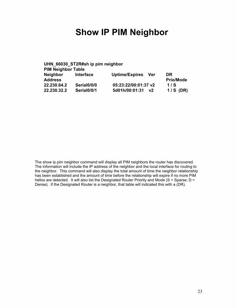
23
Show IP PIM Neighbor
UHN_66030_ST2R#sh ip pim neighborPIM Neighbor TableNeighbor Interface Uptime/Expires Ver DRAddress Prio/Mode22.230.64.2 Serial0/0/0 05:23:22/00:01:37 v2 1 / S22.230.32.2 Serial0/0/1 5d01h/00:01:31 v2 1 / S (DR)
The show ip pim neighbor command will display all PIM neighbors the router has discovered. The information will include the IP address of the neighbor and the local interface for routing to the neighbor. This command will also display the total amount of time the neighbor relationship has been established and the amount of time before the relationship will expire if no more PIM hellos are detected. It will also list the Designated Router Priority and Mode (S = Sparse; D = Dense). If the Designated Router is a neighbor, that table will indicated this with a (DR).

24
Show IP IGMP Group
UHN_66030_ST2R#sho ip igmp groupIGMP Connected Group MembershipGroup Address Interface Uptime Expires Last Reporter224.0.1.40 Serial0/0/0 01:41:18 stopped 22.230.0.6
JNN_66050_ST2R#sho ip igmp groupIGMP Connected Group MembershipGroup Address Interface Uptime Expires Last Reporter224.0.1.40 Vlan59 00:05:27 00:02:40 22.230.34.62239.255.255.250 Vlan59 00:21:27 00:02:42 22.230.34.60
JNN-66070-ST2R#sho ip igmp groupIGMP Connected Group MembershipGroup Address Interface Uptime Expires Last Reporter224.0.1.40 Vlan59 00:07:31 00:02:16 22.230.66.62
Displays the multicast groups having receivers that are directly connected to the router and that were learned through IGMP. A receiver must be active on the network at the time that this command is issued in order for receiver information to be present on the resulting display. Group Address – Lists the groups that the router currently knows about and manages. Interface – Lists the interface that the reporter’s information was received through Uptime – Displays in hours:min:sec how long the group has been known about Expires - Countdown timer when the group is to age out of the IGMP table if no further information is received for it. Stops if an IGMP-leave message is received Last Reporter – Displays the IP address of the last host to send IGMP information to the router.

25
Show IP MrouteUHN_66030_ST2R#sho ip mrouteIP Multicast Routing TableFlags: D - Dense, S - Sparse, B - Bidir Group, s - SSM Group, C - Connected,
L - Local, P - Pruned, R - RP-bit set, F - Register flag,T - SPT-bit set, J - Join SPT, M - MSDP created entry,X - Proxy Join Timer Running, A - Candidate for MSDP Advertisement,U - URD, I - Received Source Specific Host Report,Z - Multicast Tunnel, z - MDT-data group sender,Y - Joined MDT-data group, y - Sending to MDT-data group
Outgoing interface flags: H - Hardware switched, A - Assert winnerTimers: Uptime/ExpiresInterface state: Interface, Next-Hop or VCD, State/Mode
(*, 234.254.0.3), 00:09:27/stopped, RP 0.0.0.0, flags: DIncoming interface: Null, RPF nbr 0.0.0.0Outgoing interface list:Serial0/0/1, Forward/Sparse-Dense, 00:09:27/00:00:00Serial0/0/0, Forward/Sparse-Dense, 00:09:27/00:00:00
(22.230.66.60, 234.254.0.3), 00:09:27/00:00:43, flags: PTIncoming interface: Serial0/0/0, RPF nbr 22.230.64.2Outgoing interface list:Serial0/0/1, Prune/Sparse-Dense, 00:02:20/00:00:39
Source
Destination
Displays the contents of the IP Multicast routing table. Note that there are no destination prefixes displayed in this table as in a unicast routing table – it is normally a series of learned group addresses and their sourcing information. Entries can be broken into two types – source and destination paths. Source – Source paths are those coming from a sending node and can be determine from the unicast address for the source, followed by a multicast group address Destination – The destination paths are denoted by a * entry in place of the source field Both types of entries will build Incoming and Outgoing Interface lists, showing where the traffic is coming from and going to. In addition, for sparse mode routes, the RP field will include the selected Rendezvous Point for that group. If the field is populated, then any received packets for that entry will only be forwarded to the RP.

26
Basic Multicast Lab
239.254.0.3BCT 2 JNN
239.254.0.2BCT 1 JNN
239.254.0.1UHN
Multicast AddressMulticast Group
1) Multicast to Local LAN
2) Multicast from VLAN 58 to 59 on local Router
UHN
BCT 2 JNNBCT 1 JNNVLAN 58 22.230.99.126/26 Fa1/0 - 7
VLAN 59 22.230.98.62/27 Fa1/8 - 15
VLAN 58 22.230.2.254/26 Fa1/0 - 7
VLAN 59 22.230.3.254/27 Fa1/8 - 15
VLAN 58 22.230.131.126/26 Fa1/0 - 7
VLAN 59 22.230.130.162/27 Fa1/8 - 15
1. Multicast to Local LAN • Set up three Users on each BCT VLAN 59 and two users on UHN VLAN 59 • Enable multicasting with global command ip multicast routing • Configure Multicast Tester to verify multicasting on VLAN 59. • Perform show commands: sho ip mroute; sho ip igmp group; sho ip pim neighbor.
o Were there any entries? Why, why not? 2. Multicast on VLAN 58 & 59 • Establish a single sender on VLAN 58 and two receivers on VLAN 59 • Configure Multicast Tester to verify multicasting from VLAN 58 to VLAN 59 • Configure multicast over the interfaces with “ip pim sparse-dense-mode” • Perform show commands: sho ip mroute; sho ip igmp group; sho ip pim neighbor
o Were there any entries? From which commands?

27
Multicast over WAN serialUHN
BCT 1 JNN BCT 2 JNN
239.254.0.3239.254.0.2239.254.0.1Multicast Address
BCT 2 User 3BCT 1 User 2UHN User 1Sender
BCT 1 User 3 UHN & BCT 2 User 2BCT 1 & 2 User 1Receivers
BCT 2 JNNBCT 1 JNNUHNMulticast Group
123
123
1 2
3. Multicast over WAN serial • Install all users on their respective VLAN 59 • Install serial links using OSPF between routers • Enable multicasting over WAN serial links with interface command ip pim sparse-dense
mode • Configure Multicast Tester for scenario as referenced in table and run. • Perform show commands: sho ip mcast route; sho ip igmp group; sho ip pim neighbor • Perform show commands: sho ip mroute; sho ip igmp group; sho ip pim neighbor
o Were there any entries? From which commands?

28
Advanced Multicast
• Using Rendezvous Points and Bootstrap Routers• Using Multicast over mGRE tunnels• WIN-T Increment 2 Multicast Architecture• Increment 1b Multicast Integration• Troubleshooting Multicast

29
RPs for Sparse Mode Operation
(S, G) Register (unicast)(S, G) JoinsShared TreeSource Tree
(S, G) State created only along the Source Tree
RP
Rendezvous Points (RPs) PIM-SM Sender Registration • As soon as an active source for group G sends a packet, the leaf router that is attached to
this source is responsible for “Registering” this source with the RP and requesting the RP to build a tree back to that router.
• The source router encapsulates the multicast data from the source in a special PIM SM
message called the Register message and unicasts that data to the RP. • When the RP receives the Register message it does two things:
o It de-encapsulates the multicast data packet inside of the Register message and forwards it down the Shared Tree.
o The RP also sends an (S,G) Join back towards the source network S to create a branch of an (S, G) Shortest-Path Tree. This results in (S, G) state being created in all the routers along the SPT, including the RP.

30
Configuring RP
Router (config) #ip pim rp-candidate Loopback0 group-list 5• Sets loopback0 as auto-RP candidate
ip pim rp-address <Lo0 IP>• Sets the RP to the local router’s Loopback Interface
ip pim rp-candidate <I/F type> <I/F #> [group-list <acl #>] – Specifies the interface on the local router to use as a candidate for the rendezvous point for the specified multicast domains. By default, the domain prefix is 224.0.0.0/4, but specifying a more specific ACL increases that router’s priority to become the RP. ip pim rp-address <Lo0 IP> - Use this command to specify the RP address to use for the local router, which will then be announced to the rest of the network should this router be elected as the domain Rendezvous Point. The RP address is used by first hop routers to send PIM register messages on behalf of a host sending a packet to the group. The RP address is also used by last hop routers to send PIM join and prune messages to the RP to inform it about group membership.

31
Bootstrap Routers (BSRs)
• Used in PIMv2 to maintain RPs• Only a single BSR elected per multicast domain• BSR messages sent to all multicast-enabled
routers• Messages contain:
– Active BSR address– Candidate-RP mappings for each active group
The Bootstrap Router (BSR) protocol is an integral part of the PIM version 2 protocol. It is used as a means to maintain Rendezvous Point mappings for the entire multicast domain. Even though only one BSR is active at any given time, any number of RPs can be active – one RP per multicast group address. The BSR sends out messages every 60 seconds to multicast-enabled routers that are listening on the 224.0.0.13 group address. This address is local-scope only, thus the messages are propagated on a per-hop basis. The messages contain the active BSR’s address, allowing RPs to know which router to forward candidate RP (C-RP). BSR performs similarly to Auto-RP in that it uses candidate routers for the RP function and for relaying the RP information for a group. RP information is distributed through BSR messages, which are carried within PIM messages. PIM messages are link-local multicast messages that travel from PIM router to PIM router. Because of this single hop method of disseminating RP information; TTL scoping cannot be used with BSR. A BSR performs similarly as an RP, except that it does not run the risk of reverting to dense mode operation, and it does not offer the ability to scope within a domain. PIM uses the BSR to discover and announce RP-set information for each group prefix to all the routers in a PIM domain. This is the same function performed by Auto-RP, but the BSR is part of the PIM Version 2 specification. The BSR mechanism interoperates with Auto-RP on Cisco routers. To avoid a single point of failure, you can configure several candidate BSRs in a PIM domain. A BSR is elected among the candidate BSRs automatically; they use bootstrap messages to discover which BSR has the highest priority. This router then announces to all PIM routers in the PIM domain that it is the BSR.

32
Configuring BSRs
Router (config) #
ip pim bsr-candidate Loopback0 4 254• Designates router as BSR candidate, with interface Lo0
ip pim spt-threshold infinity• Allows SPT
ip pim register-source Loopback0• Ensures a single source is used for all PIM messages
ip pim bsr-candidate Loopback0 4 254 – Configures the router to announce its candidacy as a bootstrap router (BSR). • Perform this step on the RP and BSR routers. • The routers to serve as candidate BSRs should be well connected and be in the backbone
portion of the network, as opposed to the dialup portion of the network. NOTE: The Cisco IOS implementation of PIM BSR uses the value 0 as the default priority for candidate RPs and BSRs. This implementation predates the draft-ietf-pim-sm-bsr IETF draft, the first IETF draft to specify 192 as the default priority value. The Cisco IOS implementation, thus, deviates from the IETF draft. To comply with the default priority value specified in the draft, you must explicitly set the priority value to 192. ip pim spt-threshold infinity – To configure when a Protocol Independent Multicast (PIM) leaf router should join the shortest path source tree for the specified group, use the ip pim spt-threshold command in global configuration mode. To restore the default value, use the no form of this command. When this command is not used, the PIM leaf router joins the shortest path tree immediately after the first packet arrives from a new source. ip pim register-source Loopback0 – To configure the IP source address of a register message to an interface address other than the outgoing interface address of the designated router (DR) leading toward the rendezvous point (RP), use the ip pim register-source command in global configuration mode. To disable this configuration, use the no form of this command. By default, the IP address of the outgoing interface of the DR leading toward the RP is used as the IP source address of a register message.

33
Multicast over mGRE/NBMA
• TDMA network utilized NBMA for DMVPN tunneling
• Multicast traffic is not handled correctly unless configured properly
• In an mGRE-based network, the router sees an interconnected network, but is discontiguous at Layer 2
• Configure “ip pim nbma-mode”, along with “ippim sparse-mode”
Non-Broadcast, Multi-Access (NBMA) networks such as ATM and mGRE (DMVRN) are implemented in a shared-network environment. When these connections are implemented using point-to-multipoint interfaces, the NBMA cloud is configured as a Logical IP Subnet (LIS). When this form of NBMA network connectivity is used, the special nature of how broadcast and multicast traffic is forwarded must be considered in order for IP Multicast in general and PIM in specific, to operate correctly. When the ‘ip pim nbma-mode’ command is configured on an interface, the normal PIM control message processing is modified as follows: • When a Join message is received on the interface, the router puts both the interface and the
joiner (usually in the form of the joiners IP address) in the Outgoing Interface List (OIL). • When a Prune message is received on the interface, the router removes the associated
interface/joiner from the OIL. The method effectively maintains a picture of the active underlying Layer 2 topology in the OIL, which allows the router to make the appropriate forwarding decisions at Layer 3.

34
TDMA TDMA
JNN JNN
Bn CPN
Bn CPN Bn CPN
Bn CPN
FDMA serial
FDMA serial
FDMA serial
Ethernet
Ethernet
Ethernet
Ethernet
Ethernet
Ethernet
Ethernet
Ethernet
BCT 1 BCT 2
HubUHN_66030_ST2R
LO0 22.230.0.6/32
FA0/0 172.20.254.1/29
TU6605 172.21.78.1/25
TU6607 172.21.79.1/25
VLAN 59 22.230.3.254/24
DMAIN – OSPF Area 0
22.230.0.0/19
OSPF Area 0
22.230.32.0/19
JNN_66050_ST2R
LO0 22.230.32.2/32
FA0/0 172.20.78.9/29
TU6605 172.21.78.8/25
VLAN 59 22.230.34.62/27
BCP_66052_ST2R
LO0 22.230.32.9/32
FA0/0 172.20.78.17/29
TU6605 172.21.78.16/25
VLAN 59 22.230.40.62/27
BCP_66053_ST2R
LO0 22.230.32.10/32
FA0/0 172.20.78.25/29
TU6605 172.21.78.24/25
VLAN 59 22.230.44.62/27
UA 2 – OSPF Area 0
22.230.64.0/19
BCP_66072_ST2R
LO0 22.230.64.9/32
FA0/0 172.20.79.17/29
TU6607 172.21.79.16/25
VLAN 59 22.230.72.62/27
BCP_66073_ST2R
LO0 22.230.64.10/32
FA0/0 172.20.79.25/29
TU6607 172.21.79.24/25
VLAN 59 22.230.76.62/27
JNN_66070_ST2R
LO0 22.230.64.2/32
FA0/0 172.20.79.9/29
TU6607 172.21.79.8/25
VLAN 59 22.230.66.62/27
Install the above network as shown. Configure the hub and spoke routers using the configuration information from the two previous pages. Enable OSPF to operate on the tunnel interface and the interface supporting host computers. Do not configure a routing protocol for the physical interfaces connected to the TDMA cloud. Configure a static route. The TDMA router’s Ethernet interface is configured with all seven physical subnets. Configure the first subnet with “ip address” command and then the other six with “ip address” command and the “secondary” extension. Once complete, test for network connectivity using ping and trace between the user subnets. Utilize the “show ip nhrp” command to view the tunnels in place.

35
Advanced Multicast Lab
JNNJNN
HUB
Int Tu xIp pim sparse-modeIp pim nbma-mode
ip pim rp-address <Lo0 IP>ip pim spt-threshold infinityip pim bsr-candidate Loopback0 4 253ip pim rp-candidate Loopback0 group-list 5ip pim register-source Loopback0
Int Tu xip pim sparse-modeip pim nbma mode
ip pim rp-address <Lo0 IP>ip pim spt-threshold infinityip pim bsr-candidate Loopback0 4 253ip pim rp-candidate Loopback0 group-list 5ip pim register-source Loopback0
Int Tu xIp pim sparse-modeIp pim nbma-mode
ip pim spt-threshold infinityip pim register-source Loopback0
1. Use the TDMA network from the previous slide. 2. Install laptops with multicast tester on VLAN 59 on each router & enable ip pim sparse-
dense-mode on the VLAN. 3. Configure access-list 5 for BSR priority using the following lists for the JNNs
access-list 5 permit 224.0.0.0 1.255.255.255 access-list 5 permit 226.0.0.0 1.255.255.255 access-list 5 permit 228.0.0.0 1.255.255.255 access-list 5 permit 230.0.0.0 1.255.255.255 access-list 5 permit 232.0.0.0 1.255.255.255 access-list 5 permit 234.0.0.0 1.255.255.255 access-list 5 permit 236.0.0.0 1.255.255.255 access-list 5 permit 238.0.0.0 1.255.255.255
4. Configure access-list 5 for BSR priority using the following lists for the HUB access-list 5 permit 224.0.0.0 0.255.255.255 access-list 5 permit 225.0.0.0 0.255.255.255 access-list 5 permit 226.0.0.0 0.255.255.255 access-list 5 permit 227.0.0.0 0.255.255.255 access-list 5 permit 228.0.0.0 0.255.255.255 access-list 5 permit 229.0.0.0 0.255.255.255 access-list 5 permit 230.0.0.0 0.255.255.255 access-list 5 permit 231.0.0.0 0.255.255.255 access-list 5 permit 232.0.0.0 0.255.255.255 access-list 5 permit 233.0.0.0 0.255.255.255 access-list 5 permit 234.0.0.0 0.255.255.255 access-list 5 permit 235.0.0.0 0.255.255.255

36
access-list 5 permit 236.0.0.0 0.255.255.255 access-list 5 permit 237.0.0.0 0.255.255.255 access-list 5 permit 238.0.0.0 0.255.255.255 access-list 5 permit 239.0.0.0 0.255.255.255
5. Configure the rest of the multicast configuration commands listed in the above diagram as
shown above. 6. Verify multicast operations using various show commands.

37
WIN-T Inc 1 Multicast Architecture
RP
INE
LW
INE
LW
LW
INE RP
INC-1 HUB
Static group *
CPNJNN
The shelters support a multicast architecture on SIPR and NIPR networks. Multicast routing is enabled on all WIN-T routers. In the SIPR network, multicast supports user applications such as Command post of the Future (CPoF). In the NIPR network, multicast is used primarily for TACLANE SDD probes. Protocol Independent Multicast (PIM) Sparse mode protocol (more selective) is used on all TDMA interfaces and enables multicast routers to identify other multicast routers to receive packets. PIM-Dense mode (less selective) is enabled on external access interfaces, including plug and play VLANs and serial FDMA ports. An example of dense mode usage is on legacy interfaces such as MSE. For PIM-Sparse mode operations, a rendezvous point (RP) is selected. The rendezvous point in a sparse network is the collection point for all multicast routing tables and group memberships. Router configurations at both NIPR and SIPR network edges (Tier 2 or Transmission); maintain a priority scheme using the Boot Strap Routing (BSR) Protocol. The BSR protocol is configured in routers such that they select the internal router as the rendezvous point. If a TacHub is not available as first choice, the first JNN in a TDMA network is elected, then the second. A BnCP is never elected. When using multicast in tunnels, pay particular attention to tunnel configuration. Static multicast mapping is used to send unicast packets across a tunnel. The RP is responsible for building a Shared Tree (ST) for all participants in a Multicast Group. To send Multicast traffic, a Shortest Path Tree (SPT) is established from the source to the RP. Multicast traffic is sent from the source using SPT, and the RP distributes packets to members of that specific multicast group, down the ST.

38
WIN-T Inc 2 Architecture
Multicast enabled SIPR stub. Each SIPR tier 2 router connected to the INE PT interface acts as the Rendezvous Point.
VWP-1
VWP-2VWP-3
TCN
TOC-A TOC-B
TOC-ATOC-A
VWP-1VWP-1
LAW Tunnels
LAW Tunnels
LAW Tunnels
TCN TCNRP
RP RP
INE
INE
INE
COLORLESS CORE NETWORKPIM Sparse mode
*Red enclaves required to be stubs off of the colorless core.
The Increment 2 multicast architecture is a significant shift from the previous design primarily due to the nature of the NCW modems transmission capability. The tunneling system used is unicast-only. The TACLANE mini INE’s also allow for multicast IGMP messages to be bypassed through using PPK-based security associations. When multicast traffic is sent into the colorless core, the payload is encrypted inline and sent onto the MPM-1000 modem or the HNR radio with its group address intact. This allows for a much more efficient use of bandwidth, unlike the Increment 1 system of using the DMVPN implementation’s use of mapping multicast to unicast addresses. Each of the smaller nodes within a given subset – Brigade and below or even Battalion and below has a designated RP for multicast traffic within the area. Once this traffic is forwarded onto the RP and is required to leave the local stub, the Tier 2 router forwards the traffic to the CT side of the Taclane. The Taclane checks its SA mappings, and if one is found for the given group address, it is encrypted and forwarded on to the PT side of the network. This requires the Colorless Core routed network to be aware of all group address memberships in the network. Once the traffic is forwarded to the receiver’s router, it is decrypted and passed back into the Taclane CT side network.

39
INE INEINE INE INE
SRR
NCW NCW NCWLW LW
Colorless Core LINKWAY NET
LW
INE
INC-2 integration Kit
INC-2 integration Kit
RP
RP
INE
RP
NCW
*BSR Border
Igmp proxy-serviceMroute-proxy interfacesIgmp helper to INC-2 RP
igmp helper to INE PT
*
*
Multicast enabled mGREtunnels
Unicast only mGRE tunnels
cost 1050
cost 1100
HUB Node
PIM DR
Disable PIM Disable PIM
Colorless Router
NIPR Router
The Increment 1b package is a hybrid of these two implementations. While the package gives Increment 1 systems the capability of using both methods, PIM is disabled between the SIPR/NIPR tier 2 routers and the 1b interface. This forces any multicast traffic to forward over the Linkway or FDMA network to the Hub node, which is configured as the BSR for the network. This traffic is then forwarded at the Hub node between its Inc 2 and Inc 1 enclaves.

40
LW
INE
RP
INE
RP
NCW
*BSR Border
*
Int Loopback0:Ip igmp proxy-serviceIp igmp helper-address <int B>
All tunnel interfaces:Ip igmp mroute-proxy Loopback0
Int A:ip pim bsr-borderip igmp static-group *
Int AInt B
tunnel interface:ip ospf cost 1100
Int B:ip pim bsr-borderip pim dr-priority 100ip igmp igmp-helper address <INE PT>
Int C:ip igmp static-group *
Int C
INC-2 HUB SIPR ROUTER Config: INC-1 HUB SIPR ROUTER Config:
Colorless Router
This interface must be the PIM designated router on the LAN.
NIPR Router
INC-2 Enclave INC-1 Enclave
HUB Node Configuration Highlights

Insert Tab #5 Here

Quality of Service

2

3
Quality of Service (QoS)
• QoS is the implementation of tools on a network to achieve optimum functionality within the constraints of the network
• Requirements– Understand the network– Understand organizational
requirements– Determine network applications
which support the organizational requirements
– Implement QoS tools on the networkElementary network of
two computers connected to each other by a cable so that they can share data.
QoS is the implementation of tools on a network to achieve optimum functionality within the constraints of the network. Achieving optimum functionality requires understanding the network. In addition, the goals and operational requirements of the organization must be understood. The applications, which support these goals and requirements, must be determined. Then QoS is implemented to achieve optimum functionality to support the organization within the constraints of the network. For example: An analysis of the elementary network depicted on the left side of the diagram above.
• The network consists of two computers. • These two computers are connected by a single cable. • The two computers auto negotiate their speed and duplex settings. • The network speed and throughput is 100 Mbps. • The computers are in full duplex mode. • Applications can only run between these 2 computers
o Therefore, each networking application has exclusive use of the network whenever it needs it.
• The quality of the networking services depends on the configuration and capabilities of each computer’s operating system.
• Depending upon the application being run, this network may or may not benefit from additional QOS configuration.
Our discussion of QoS in this lesson will focus on the example network on the following slide.

4
Example Network
NIPR Router Case(Sp 2-7: Bn Case B)
For DT/LUT Only
SIPR Router Case(Sp 2-7: Bn Case A)
Vlan 175
Vlan 175
Vlan 6
Vlan 6
SEP
TLNT2R
NIPR AdaptiveRouter Case
STTLinkway
MPM-100
TLST2R
SIPR AdaptiveRouter Case
Colorless Router Case
3560
CLR
M/C
M/C
M/C
M/C
M/CNT2R
100BaseTX (Copper)TFOCA-II100BaseFX (Fiber)
Required Tunnels and
configuratio
n to
communicate w/Inc 2
ST2R
In this lesson, Quality of Service (QOS) will be discussed in the context of the example network above.

5
Traffic Analysis
• Any network carries a variety of traffic
• Traffic Analysis is determining the traffic carried on a given network.
TCP
UDP
RTP
LSA
STP
?SMTP
HTML
NIPR Router Case(Sp 2-7: Bn Case B)
For DT/LUT OnlySIPR Router Case
(Sp 2-7: Bn Case A)
Vlan 175
Vlan 175
Vlan 6
Vlan 6
SEP
TLPT
CT
NT2R
NIPR AdaptiveRouter Case
STTLinkway
MPM -100
TLPT
CT
ST 2R
SIPR AdaptiveRouter Case
Colorless Router Case
3560
CLR
M/C
M/ C
M/C
M/C
M/CNT2R
100BaseTX(Copper)TFOCA-II100BaseFX(Fiber)
ST2R
Any network carries a variety of traffic. Traffic Analysis is determining the traffic carried on a given network.

6
Traffic Analysis of the Example Network
• SIPR Serial WAN• NIPR Serial WAN• TDMA WAN
NIPR Router Case
(Sp 2 -7 : Bn Case B )
For DT / LUT Only
SIPR Router Case
( Sp 2 - 7 : Bn Case A )
Vlan 175
Vlan 175
Vlan 6
Vlan 6
S
E
P
TL
PT
CT
NT 2 R
NIPR AdaptiveRouter Case
STT
Linkway
MPM - 100
TL
PT C
T
ST 2 R
SIPR Adaptive
Router Case
Colorless Router Case
3 5 60
CLR
M / C
M / C
M / C
M / C
M / CNT 2 R
100 BaseTX ( Copper )
TFOCA - II
100 BaseFX ( Fiber )
ST 2 R
The example network has SIPRnet and NIPRnet. The interface, which carries the consolidated traffic of SIPRnet, is referred to as the SIPR WAN interface. The interface, which carries the consolidated traffic of NIPRnet, is referred to as the NIPRnet WAN interface. The traffic from the SIPR WAN interface and the NIPR WAN interface reaches the colorless router. The colorless router then consolidates the traffic from both networks into the TDMA WAN.

7
Existing QoS Implementation
The above graphic shows the existing Increment 1 QoS implementation points.

8
Traffic Allocations
34%
3%
5%
35%
20%
3%
SIPR VoIPVoice SignalingNetwork ControlTime SensitiveCollaborationDefault
35%
5%6%3%5%
20%
7%
10%
5% 4%
SIPR VoIP(PQ)NIPR VoIP(PQ)Transit VoIP(PQ)Voice SignalingNetwork ControlTime SensitiveTransit DataCollaborationNIPR DataDefault
35%
6%3%
5%7%
40%
4%
NIPR VoIPTransit VoIPVoice SignalingNetwork ControlTransit DataNIPR DataDefault
TDMA
SIPR Serial NIPR Serial
The graphic above displays the results of an analysis of the traffic found on the existing Increment 1 network. Traffic is broken down into several different types of traffic (classified), and then allocated a certain percentage of the bandwidth on the designated link.

9
Traffic Protocols and Packet Size
Relative Packet Sizes
File transferVideo
TelnetVoice
TCP+IP
UDP+IP
• The TCP/IP suite uses two protocols to carry traffic -- TCP and UDP
• IP protocol encapsulates a TCP or UDP segment into a packet
• Ethernet then puts the IP packet into a frame
• This produces frames in a variety of sizes
Traffic exists on the network in packets of various sizes. Recall that a packet consists of an IP header and all data above the network layer in the TCP/IP suite. In the TCP/IP suite, the transport protocol can be either UDP or TCP. Additionally, the amount of data in a UDP or TCP segment is determined by the network application. The table above graphically depicts the relative size of packets from different network applications. Notice that Telnet uses TCP and has a packet size approaching the size of a voice packet. The voice packet uses UDP. A video packet also contains a UDP segment. However, it is larger than a voice packet. File transfers are an example of an application, which uses the maximum Ethernet packet size. That size is 1500 bytes. File transfers also use TCP at the transport layer.

10
Characteristics of an Interface Propagating Outgoing Traffic
• First In First Out (FIFO) Buffer– Jitter– Queuing Delay– Tail Drop
TCP
UDP
RTP
LSA
STP
?SMTP
HTML
The router uses a first in first out buffer to process traffic for an outgoing interface. This buffer has effects on outgoing traffic. Three of these effects are jitter, queuing delay, and tail drop.

11
First In First Out (FIFO)
• The outgoing interface– Puts packets in its queue in the order the packets arrive– Sends the packets from the front of the queue out the interface
• Jitter: Packets of different sizes will take different amounts of time to send
• Queuing Delay: The time elapsed from when a packet enters the queue until it exits the interface
• Tail Drop: more frames arrive at the interface than the interface can handle
FIFO Queue Depth 50 Frames
FastEthernet 0/0
First In First Out
Last In Last Out
First In First Out (FIFO): F0/0 is going to send the packets out based on which packet arrives first. This is referred to as First In First Out (FIFO). Packets containing UDP and TCP segments of various sizes will be intermingled on the transmission medium. Queuing delay: The outgoing interface has a FIFO buffer where it stores packets. This buffer is called a queue. The interface sends the packets from the queue in the order they are received. The time elapsed from when a packet enters the queue until it exits the queue is Queuing Delay. Jitter: Notice the intermixing of the smaller packets with the larger packets. The varying packet size causes the time delay between packets to vary. This variation in delay is called jitter. Tail Drop: If more packets arrive at the interface than the interface can handle the packets will be dropped. This is referred to as tail drop.

12
Data Quality
• The user expects certain performance from data traffic– While web browsing rapid display of the page is
expected, therefore the user develops the perception of network speed
– When transferring files, files are expected to transfer successfully and rapidly
– When doing e-mail it is expected that the mail will go through
Depending on the application being used, the user applies different criteria to the network. When the application is data based the user’s primary criteria is successful completion of the transfer of data. That is why applications, which perform data transfer, use TCP. The next criteria the user most often applies to the network is speed. The user’s perception and requirement for speed varies from one application to another. Possibly the user may believe the term bandwidth is a synonym for speed. For a network administrator, the more correct term for speed is network throughput. When working with webpages, the user expects the pages to update rapidly. If there is video or sound on the webpages, the user expects a certain level of performance for those also. When there is video or sound, the user will apply the same performance criteria they would use for a phone call or a video teleconference. For webpages that contain a mix of text, pictures, video, and sound, both TCP and UDP are used to transfer the data. Text and graphics are transferred using TCP. Voice and video are transferred using UDP. When transferring files, the user looks for successful completion as well as speed. When doing e-mail, the user expects e-mail will go through. Whether the e-mail takes a few seconds or a few minutes the user may not even be able to tell. Seconds and minutes are really long times relative to network throughput. Therefore, a relatively slow throughput can still satisfy the users’ needs.

13
Voice / Video Quality
• The user expects certain performance from voice and video of IP– A certain sound quality is
expected– A certain video quality is
expected
Telephone users notice the quality of their phone calls. Three primary characteristics of Voice over IP phone calls affect the user’s perception of voice call quality: • Packet loss greater than 1% — this means .02 seconds of sound from the person talking is
missing every 2 seconds. Voice uses UDP; the packet has only one chance to get from the source to the destination.
• Jitter — the network has variable delay causing the packets to arrive at varying intervals of
time exceeding 30ms. Jitter indicates information about incoming packets not outgoing. That means jitter indicates the quality of the incoming voice not the quality of the outgoing voice.
• Total delay greater than 150ms (milliseconds) — remember that conversations are two
way. Delay is the time from when one person stops talking and starts hearing the other person.
Queuing delay and jitter have already been discussed. Those are variable delays. Fixed delays are propagation delay and serialization delay. Propagation delay is the time required for a signal or a bit to travel the length of the medium (cable, fiber, air etc). Formula: length of the medium / speed of 1 bit through the medium = propagation delay. Serialization delay is the time required to put a packet out of the interface and on to the medium. Examples: Voice and Data Packets over UTP CAT-5 Cable • 10 meters / 2.1* 10^8 = 0.0004 ms • 1000 km / 2.1* 10^8 = 4.8 ms

14
Voice and Data Packets over Satellite • 35,786 kilometers / 3.0 * 10^8 = .12 sec or about 0.25 sec round trip Serialization delay is the time required to put a packet out of the interface and on to the medium. • Bits in a packet / link speed = serialization delay Voice Packets • Assume G711 CODEC 160 bytes every 20 ms = 50 pps (packets per second) • 160 bytes = 1280 bits • Serialization delay for 1 packet:
1280 bits / 100 Mbps = 0.00001280 seconds = 0.0128 ms (milliseconds) Data Packets • 1500 byte MTU • 1500 bytes =12000 bits • Serialization delay for 1 packet:
12000 bits / 100 Mbps = 0.00012 seconds = 0.12 ms (milliseconds) During Video Teleconferences (VTCs) users expect the same voice quality. Therefore, everything that has been discussed pertaining to voice above still pertains. The video portion of the teleconference places additional traffic on the network.

15
Data & Voice Sharing Bandwidth
• TCP Windowing– Congestion Window (CWND)
• TCP Packet Size– Lost or dropped TCP packets will be resent.– The header size is 20 bytes. Therefore each packet will be 20 bytes or
greater.• UDP Packet Size
– Lost or dropped UDP packets are not resent.– Have a header of 8 bytes. Therefore each packet will be 8 bytes or
greater.• Voice Packet
– Size– Quantity per second
On 100Mbps networks, voice and data can share the bandwidth with no negative effects on voice quality most of the time. In fact, the negative effects on voice may occur so seldom that the problem is not noticed. When voice and data are sharing bandwidth, voice packets can be delayed or lost completely. Data using TCP can be delayed. Data using UDP can be delayed or lost. To understand this several things must be recognized and considered. TCP Windowing and Congestion Window (CWND): Reacts to network congestion by slowing down TCP traffic. TCP Segments: Lost or dropped TCP packets will be resent. The header size is 20 bytes. Therefore each packet will be 20 bytes or greater. UDP Segments: Lost or dropped UDP packets are not resent. The header size is 8 bytes. Therefore each packet will be 8 bytes or greater. Voice Segments: Voice packets using G.711 codec are typically 160 bytes sent at 50 packets per second. IP Header: the header size is 20 bytes. Frames: The header size is 38 bytes minimum. The maximum frame size is set by the Maximum Transmission Unit (MTU). For Ethernet the MTU is up to 1500 bytes. 1500 bytes is a typical value. A minimum frame size of 64 bytes is required.

16
Oversubscription
• Oversubscription of a link can result when traffic from high bandwidth links is routed or switched to lower bandwidth links.
• QoS is needed on this example network because traffic will be sharing the 4 Mbps link at the STT
NIPR Router Case
(Sp 2 -7 : Bn Case B )
For DT / LUT Only
SIPR Router Case
( Sp 2- 7 : Bn Case A )
Vlan 175
Vlan 175
Vlan 6
Vlan 6
S
E
P
TL
PT C
T
NT 2 R
NIPR AdaptiveRouter Case
STT
Linkway
MPM - 100
TL
PT C
T
ST 2 R
SIPR Adaptive
Router Case
Colorless Router Case
3 5 60
CLR
M / C
M / C
M / C
M / C
M / CNT 2 R
100 BaseTX ( Copper )
TFOCA - II
100 BaseFX ( Fiber )
ST 2 R
1 Gbps Interfaces 4 Mbps
Interface
Colorless Router
Oversubscription of a link can easily result when traffic from high bandwidth links is routed or switched to lower bandwidth links. It can also result when traffic arrives from multiple links and is routed or switched out another link. If the traffic is a combination of voice, video, and data, oversubscription of the link will diminish the quality of the voice and video. Notice in our example network that a 1Gbps interface is connected to the STT. On the STT, the satellite bandwidth via the Linkway modem is 4Mbps. Traffic from the 1 Gbps interface that exceeds 4 Mbps at the STT will be dropped. QoS is needed on this example network because traffic will be sharing the 4 Mbps link at the STT. QoS is required to manage the network traffic.

17
Implementing QoS
• QoS is not built into a network• QoS exists after deploying features that
implement it throughout the network.
QoS is not built into a network. QoS exists after deploying features that implement it throughout the network.

18
Path to Establishing QoS
• Traffic Analysis– What types of traffic are running on the network?– How much bandwidth is used by each type of traffic?
• Traffic Classification– How important is each type of traffic?– Group traffic with equal importance together.
• Priority / Policy for Traffic Classes– How should the different groups of traffic be handled (priority, bandwidth)?
• Translate the Classifications to the router– Use class-maps to group the traffic.– Define characteristics used to recognize the traffic.
• Translate the Priority / Policy to the Router– Enter policy-maps defining priority and bandwidths to be allocated to the
traffic classes.• Assign the Policy to Interfaces
– Use service-policy to assign the policy to outgoing or incoming traffic
This lesson will take the path above to establish QoS on our example network.

19
QoS Toolset
•Shaping•Marking •Classification •Congestion Avoidance•Congestion Management
Managing traffic with QoS is also referred to as traffic engineering of paths. By using QoS tools, the network engineer is defining Policy Based Routing (PBR). Rules define the policies. These policies are referred to as a Per Hop Behavior (PHB). Shaping is the management of traffic flow to keep traffic flow within constraints found within the network. Marking is the application of a code to a frame or a packet based on defined criteria. For instance, an IP phone marks packets based on whether the packet is carrying voice or data from the phone. Marking can be used to assign a distinct code to a packet when the packet does not already contain a unique identifying characteristic. Marking also includes changing a packets current marking to a different marking. Classification is the assignment of packets to a group/class based on characteristics of the packet. A characteristic may be the packet’s marking, another characteristic, or a combination of characteristics. Congestion Avoidance is the management of packet flow before congestion occurs at an interface. Congestion Management is the management of packets to try to achieve acceptable service for all network traffic.

20
Shaping
• Shaping reduces throughput on an interface• Shaping is applied to interfaces as needed to manage
constraints found in the network• Shaping affects outbound traffic not inbound traffic• In our example network shaping will be applied to the
interface facing the Linkway modem
Shaping reduces throughput on an interface. It is applied to interfaces as needed to manage constraints found in the network. Shaping affects outbound traffic not inbound traffic. In our example network, shaping will be applied to the interface facing the STT. The choice is made to limit traffic going to the STT since the STT limits the traffic to 4 Mbps.

21
Marking
• Differentiated Services Model – Also known as DiffServ.– Provides “6” bits in the IP header to group traffic.– These groups are referred to as DSCPs (Differentiated Services Code
Points).
Differentiated Services Code Points
EFExpedited forwarding (EF)
AF11, AF12, AF13, AF21,AF22, AF23, AF31, AF32,AF33, AF41, AF42, AF43
Assured forwarding (AF)
CS1, CS2, CS3, CS4, CS5,CS6, CS7
Class selector (CS)
DSCP BE (default)Best effort (BE)
DSCPsPHB
One of the most common marking tasks is the setting of Differentiated Services Code Point (DSCP) values. Six bits in the IP header identify 64 possible Differentiated Services Code Point (DSCP) values. The chart above identifies 21 Differentiated Services Code Point (DSCP) named values. These names are defined in RFCs, which define DSCP. The RFCs also identify how packets marked by each of the 21 named values should be handled. This handling of the packet is called a Per Hop Behaviors (PHB). In general, 21 values are sufficient to provide desired QoS results. This enables traffic to be grouped into 21 PHBs. Additionally, these 21 values are structured for backward compatibility with other ways the 6 bits were/are used.

22
Differentiated Services Code Point (DSCP) Values
Binary DecimalBest effort (BE) BE 000000 0
cs1 001000 8cs2 010000 16cs3 011000 24cs4 100000 32cs5 101000 40cs6 110000 48cs7 111000 56af11 001010 10af12 001100 12af13 001110 14af21 010010 18af22 010100 20af23 010110 22af31 011010 26af32 011100 28af33 011110 30af41 100010 34af42 100100 36af43 100110 38
Expedited forwarding (EF) ef 101110 46
Class selector (CS)
Assured forwarding (AF)
Per Hop Behavior (PHB)
Recall that RFCs identify how packets marked by each of the 21 named values should be handled. This handling of a packet is called a Per Hop Behavior (PHB). A PHB is a description of the forwarding actions applied to a packet. A PHB can: • Define the amount of bandwidth the packets are given relative to another PHB. • Define the priority of packets relative to another PHB. • Define the dropping of rate packets. The table above provides information pertaining to each PHB named value. • Column 1 identifies the 4 groups of defined PHBs. • Column 2 identifies the name of a PHB in the group. • Column 3 identifies the binary value. • Column 4 identifies the decimal value.

23
Marking for Example Network
Traffic PHB DSCP
SIPR Voice EF 46
NIPR Voice EF 46
Transit Voice EF 46
Network Control CS6 48
Call-Signaling CS3 24
Critical Servers AF21 18
SIPR Data AF23 22
CPOF AF31 26
VTC AF32 28
Transit Data AF41 34
NIPR Data AF42 36
Management AF43 38
Best-Effort 0 0
In the network, required marking must be done before classification into groups. In the planning phase, marking and classification are interrelated. This is because the DSCP marking is often used as criteria to group traffic. Therefore, very often packets with the same DSCP value are placed in the same group. In the slide above, the planner identified the Traffic, the Per Hop Behavior (PHB) and the Differentiated Services Code Point (DSCP) value.

24
Traffic Classification
• Classify the various traffic on the network into groups
• Write a plan describing how different groups of traffic are to be handled.– Situation– Priority– Type of Traffic– How much traffic– Etc
Once the traffic on the network is known; then traffic that requires similar handling is placed into groups. Grouping is done based on organizational requirements. How critical is the application generating the traffic to the organizations operation? Access to web pages from the internet may be useful but not essential. Access to web pages from within the organization may be critical. Does delaying the traffic make the traffic useless? For example, delayed traffic can make voice and video garbled and useless. Is the traffic TCP or UDP based? How much traffic is essential? Is support needed for 10 phone calls or 20?

25
Traffic Classifications for Example Network
SIPRVoIPFlash Override 41
Flash 42Immediate 44
Priority 45Routine 46
TransitVoIPFlash Override 41
Flash 42Immediate 44
Priority 45Routine 46
NIPRVoIPFlash Override 41
Flash 42Immediate 44
Priority 45Routine 46
VoiceSig CS5NetworkControl CS6SIPRData AF21, AF22, AF23TransitData AF23VTC AF43Streaming AF31NIPRData AF23Management CS2
The planner has now placed traffic into groups as shown above.

26
Congestion Management
• Congestion Management is accomplished by implementing queues which process traffic before it is released to the FIFO queue
• The traffic which will be competing for 4 Mbps of bandwidth at the STT has been identified
Analysis of the network identified the need for quality of service. Detailed analysis of the traffic has been completed. There are multiple types of network traffic essential for the organizations operation. The following traffic will be competing for 4 Mbps of bandwidth at the STT. • SIPR VoIP - SIPR VoIP calls • NIPR VoIP – NIPR VoIP calls • Transit VoIP – Transit VoIP calls • Network Control – all routing updates, ISAKMP messaging…etc • Call Signaling – SIPR, NIPR and Transit VoIP call signaling • Time Sensitive – Critical Servers and all other SIPR traffic • Collaboration – CPOF and VTC traffic • Transit Data – Transit Data • NIPR Data – NIPR Data • Management – Management traffic

27
Congestion Management Design
• Congestion management design depends on selection from a number of queuing strategies
• Best practice in this network is to use Low-Latency Queuing (LLQ)
Low-Latency Queuing (LLQ) is the selected queuing strategy because it provides the best support and set of options on a network, which includes voice, video, and data.

28
Low-Latency Queuing (LLQ)
100Mbps connections
4Mbps connection
• Implementing LLQ can prioritize traffic across an interface.
Implementing LLQ can prioritize traffic across an interface. LLQ can reserve a certain amount or percentage of bandwidth to be used by each class of traffic. LLQ can also assign traffic to a queue, which has a certain amount of bandwidth and has priority to be processed before other queues.

29
Low-Latency Queuing (LLQ)
Low-Latency Queuing (LLQ) Queuing Strategy
Priority Queue (PQ)
Class Based Weighted Fair Queue (CBWFQ)
Class Based Weighted Fair Queue (CBWFQ)
Class Based Weighted Fair Queue (CBWFQ)
Class Based Weighted Fair Queue (CBWFQ)
Class Based Weighted Fair Queue (CBWFQ)
Class Based Weighted Fair Queue (CBWFQ)
Class Based Weighted Fair Queue (CBWFQ)
Class Based Weighted Fair Queue (CBWFQ)
Class Based Weighted Fair Queue (CBWFQ)
Scheduler
FIFO
LLQ combines the concept of a priority queue (PQ) with Class Based Weighted Fair Queues (CBWFQ). Priority queues get allocated bandwidth and priority in processing the packet. If required there can be more than one priority queue. The DSCP value of packets placed in a PQ is typically the PHB named EF. Class-based weighted fair queues get an allocated bandwidth. The DSCP value of packets placed in a CBWFQ is typically one of the PHB named values. Although any of the 64 DSCP values can be used. The scheduler processes queues ensuring that each queue gets its allocated resources, those resources being priority and bandwidth. The scheduler moves the packets into the first in first out buffer, from which the hardware interface places the packets on the medium.

30
Modular QoS Command-Line (MQC)
• Modular QoS CLI (MQC) is the tool that Cisco uses to define the implementation of QoS on an IOS device. – MQC is used to create QoS traffic policies and then to associate these
policies to the device’s interface(s). – Each traffic policy has two components:
• Class-Map: classifies (or groups) traffic – Commands used to map traffic to a common group (class).
• Policy- Map: defines how the traffic should be processed– Commands used to define policies to be applied to a specific group (class) of traffic
or groups (classes) of traffic.– Service-Policy
• Command used to assign a policy map to an interface.• One Service-Policy may be applied to more than on interface.
QoS planning has been completed. Now it is time to implement QoS on the colorless router. Modular QoS CLI (MQC) is the tool that Cisco uses to define the implementation of QoS on an IOS device. MQC is used to create QoS traffic policies and then to associate these policies to the devices’ interface(s). Each traffic policy has two components: a traffic class that groups traffic and a traffic policy that defines how the traffic should be processed. Class-Map Commands used to map traffic to a common group (class). Policy- Map Commands used to define policies to be applied to a specific group (class) of traffic or groups (classes) of traffic. Service-Policy Command used to assign a policy map to an interface. One Service-Policy may be applied to more than on interface. As the name MQC implies, configuration is done using the command line interface, specifically configuration mode.

31
Shaping the Traffic Using MQC
• Limit the output of the colorless router traffic to STT to 4 Mbps
NIPR Router Case
(Sp 2 -7 : Bn Case B )
For DT / LUT Only
SIPR Router Case
( Sp 2- 7 : Bn Case A )
Vlan 175
Vlan 175
Vlan 6
Vlan 6
S
E
P
TL
PT C
T
NT 2 R
NIPR AdaptiveRouter Case
STT
Linkway
MPM - 100
TL
PT C
T
ST 2 R
SIPR Adaptive
Router Case
Colorless Router Case
3 5 60
CLR
M / C
M / C
M / C
M / C
M / CNT 2 R
100 BaseTX ( Copper )
TFOCA - II
100 BaseFX ( Fiber )
ST 2 R
policy-map qosPARENTclass class-defaultshape average 4096000
interface GigabitEthernet0/1.106service-policy output qosPARENT
Service policies require that a policy-map exist defining the rules to be applied to the traffic. Policy-maps require class-maps that define groups of traffic exist. There is one class-map, which always exists. It is always available to a policy-map. That class-map is the class-default. The class-default class is used to classify traffic that does not fall into one of the defined classes. policy-map qosPARENT class class-default shape average 4096000 interface GigabitEthernet0/1.106 service-policy output qosPARENT The above configuration meets the requirements of MQC. The user starts from global configuration mode. policy-map qosPARENT creates a new policy-map and puts the command line into p-map configuration mode class class-default assigns Class-map class-default to the policy map. shape average 4096000 states that all traffic processed by class-default is to be processed by the router at an average rate of 4Mbps. Next, the user changes to interface configuration mode by issuing the command interface GigabitEthernet0/1.106 service-policy output qosPARENT applies the policies identified in qosPARENT to the traffic going out the interface. The end result is all traffic is handled by the class class-default policies. Therefore, all traffic is sent to the interface FIFO buffer at an average rate of 4 Mbps. What this has accomplished is moving the congestion point from the STT to this interface. Now a set of rules must be built to manage the traffic congestion at this interface. First, the traffic must be grouped into groups using class-map commands.

32
Class-Map Command
• Class-Map commands are used to group traffic based on defined criteria
• A wide range of criteria can be used– DSCP values– Protocols– Access Control Lists– Interface– And others
Format of the class-map command: class-map class-map-name [match-all | match-any] The match-all and match-any Keywords of the class-map Command The command syntax for the class-map command includes two keywords: match-all and match-any. The match-all and match-any keywords need to be specified only if more than one match criterion is configured in the traffic class. • The match-all keyword is used when all of the match criteria in the traffic class must be met
in order for a packet to be placed in the specified traffic class. • The match-any keyword is used when only one of the match criteria in the traffic class must
be met in order for a packet to be placed in the specified traffic class. • If neither the match-all keyword nor match-any keyword is specified, the traffic class will
behave in a manner consistent with match-all keyword. Once the class-map command has been entered, the prompt will be similar to: Router(config-cmap)# Now items to match will be entered such as: Router(config-cmap)#match dscp ef Many possible match commands exist.

33
Class Maps for Example Network
• class-map match-any VOICE-queue• class-map match-any VIDEO-queue• class-map match-all CPOFLegacy• class-map match-all VSigLegacy• class-map match-all NDataLegacy• class-map match-any DATA-queue• class-map match-any NC-queue• class-map match-all TDataLegacy• class-map match-all VTCLegacy
Following are the contents of the class maps for the example network.

34
class-map match-any VOICE-queue
class-map match-any VOICE-queuematch ip dscp 49 match ip dscp 41 match ip dscp 42 match ip dscp 44 match ip dscp 45 match ip dscp ef match ip dscp cs5
class-map match-any VIDEO-queue
class-map match-any VIDEO-queuematch ip dscp 33 match ip dscp af41 match ip dscp af42 match ip dscp 37 match ip dscp af43 match ip dscp cs4

35
class-map match-all CPOFLegacy
class-map match-all CPOFLegacymatch dscp af31 match access-group name SIPR-Traffic
class-map match-all VSigLegacy
class-map match-all VSigLegacymatch dscp cs3

36
class-map match-all NDataLegacy
class-map match-all NDataLegacymatch dscp af42
class-map match-any DATA-queue
class-map match-any DATA-queuematch ip dscp 25 match ip dscp af31 match ip dscp af32 match ip dscp 29 match ip dscp af33 match ip dscp cs3 match ip dscp 17 match ip dscp af21 match ip dscp af22 match ip dscp 21 match ip dscp af23 match ip dscp cs2 match ip dscp 9 match ip dscp af11 match ip dscp af12 match ip dscp 13 match ip dscp af13 match ip dscp cs1 match ip dscp default

37
class-map match-any NC-queue
class-map match-any NC-queuematch ip dscp cs7 match ip dscp cs6
class-map match-all TDataLegacy
class-map match-all TDataLegacymatch dscp af41 match access-group name Transit-Traffic

38
class-map match-all VTCLegacy
class-map match-all VTCLegacymatch dscp af32

39
Policy-Map Command
• Policy-map commands are used to create class policies that make up the service policy – For each class in the policy map one or more of the following
commands can be used• priority• bandwidth• queue-limit or random-detect• fair-queue (for class-default class only)• And others
policy-map policy-map-name Then classes are assigned to the policy map. Router(config-pmap)# class {class-name | class-default} Then policies are assigned for the class Example: Router(config-pmap-c)# bandwidth percent 20 (guarantees 20% of the bandwidth to this class) Or Router(config-pmap-c)# bandwidth 20 (guarantees 20 kbps of the bandwidth to this class) Or Router(config-pmap-c)# priority percent 20 (guarantees 20% of the bandwidth to this class and that this queue will be processed before other queues) Or Router(config-pmap-c)# priority 20 (guarantees 20 kbps of the bandwidth to this class and that this queue will be processed before other queues) Notice only 1 of the previous commands would be applied. Additional commands can also be part of the policy. For example, commands which determine the size of a queue and when packets are dropped for the class.

40
Congestion Avoidance
• DSCP based WRED is applied to all queues that have the potential of containing TCP traffic.
• DSCP based WRED uses the AF drop preference values to influence drop probabilities as queues fill.
• This will allow more critical TCP sessions to continue while less critical sessions are dropped.
Congestion avoidance involves the controlled dropping packets. The tools are applied to TCP traffic not UDP. Remember a dropped packet containing UDP means the data is lost. A dropped packet containing a TCP segment is resent by the source node when it is not acknowledged by the receiving node. Weighted Random Early Detection (WRED) is used for congestion avoidance. Its implementation is described next.

41
Random Detect Policy
This command creates a custom profile for the selected DSCP value.random-detect dscp dscp-value min-threshold max-threshold drop-probabilityFor packets with the DSCP value 32(dscp-value)Start discarding packets once the average queue depth = 50(min-threshold) packetsIf the queue depth grows beyond 50(min-threshold) discard more and more packets such that as the average queue depth approaches 100(max-threshold) then 1 in 10 i.e. drop-probability packets is being droppedIf the queue depth exceeds 100 drop all packets until the queue has less than 100 packets
random-detect dscp 32 50 100 10
Enables WRED using the DSCP value to calculate the drop probability for the packet. There are default drop profiles for each named PHB.
random-detect dscp-based
CommentCommand
Weighted Random Early Detection (WRED) is enabled using DSCP values by the command random-detect dscp-based. Custom processing of a specific dscp value is set by the command: random-detect dscp dscp-value min-threshold max-threshold drop-probability

42
Policy-Maps For Example Network
• policy-map qosCHILD• policy-map Legacy-Remark• policy-map qosPARENT
Following are the contents of the policy maps for our example network.

43
Policy-Map qosCHILD
policy-map qosCHILDclass NC-queue
priority percent 10class VOICE-queuepriority percent 50
class VIDEO-queuebandwidth percent 20random-detect dscp-basedrandom-detect dscp 32 50 100 10 random-detect dscp 33 99 100 10 random-detect dscp 34 99 100 10 random-detect dscp 36 99 100 10 random-detect dscp 37 99 100 10 random-detect dscp 38 50 100 10
class DATA-queuebandwidth percent 20random-detect dscp-basedrandom-detect dscp 0 50 100 2 random-detect dscp 8 50 100 2 random-detect dscp 9 99 100 10 random-detect dscp 10 99 100 10 random-detect dscp 12 99 100 10 random-detect dscp 13 99 100 10 random-detect dscp 14 50 100 2 random-detect dscp 16 50 100 2 random-detect dscp 17 99 100 10 random-detect dscp 18 99 100 10 random-detect dscp 20 99 100 10 random-detect dscp 21 99 100 10 random-detect dscp 22 50 100 2 random-detect dscp 24 50 100 2 random-detect dscp 25 99 100 10 random-detect dscp 26 99 100 10 random-detect dscp 28 99 100 10 random-detect dscp 29 99 100 10 random-detect dscp 30 50 100 2
policy-map Legacy-Remark
policy-map Legacy-Remarkclass CPOFLegacyset dscp af22class VTCLegacyset dscp af43class NDataLegacyset dscp af23class TDataLegacyset dscp af23class VSigLegacyset dscp cs6

44
Policy-Map qosPARENTpolicy-map qosPARENT
class class-defaultshape average 4096000service-policy qosCHILD
Discussed with the service-policy command
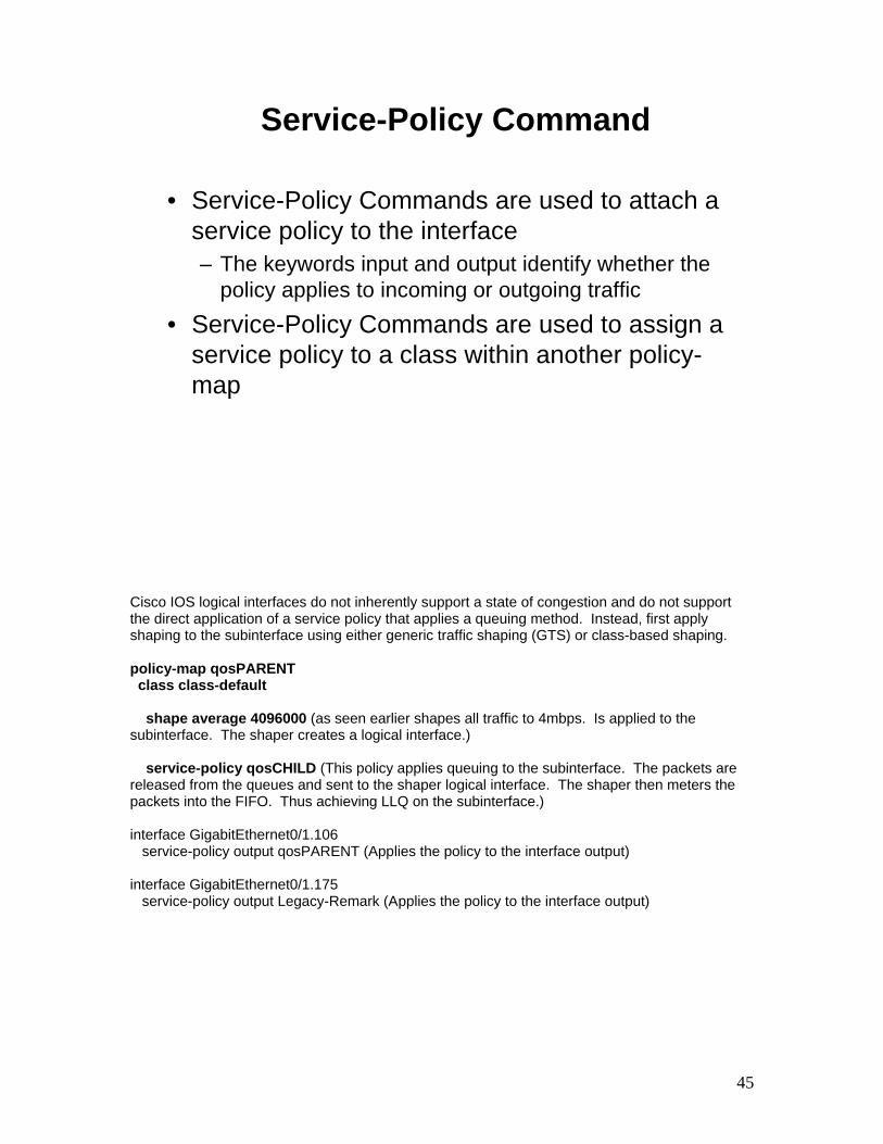
45
Service-Policy Command
• Service-Policy Commands are used to attach a service policy to the interface – The keywords input and output identify whether the
policy applies to incoming or outgoing traffic• Service-Policy Commands are used to assign a
service policy to a class within another policy-map
Cisco IOS logical interfaces do not inherently support a state of congestion and do not support the direct application of a service policy that applies a queuing method. Instead, first apply shaping to the subinterface using either generic traffic shaping (GTS) or class-based shaping. policy-map qosPARENT class class-default shape average 4096000 (as seen earlier shapes all traffic to 4mbps. Is applied to the subinterface. The shaper creates a logical interface.) service-policy qosCHILD (This policy applies queuing to the subinterface. The packets are released from the queues and sent to the shaper logical interface. The shaper then meters the packets into the FIFO. Thus achieving LLQ on the subinterface.) interface GigabitEthernet0/1.106 service-policy output qosPARENT (Applies the policy to the interface output) interface GigabitEthernet0/1.175 service-policy output Legacy-Remark (Applies the policy to the interface output)
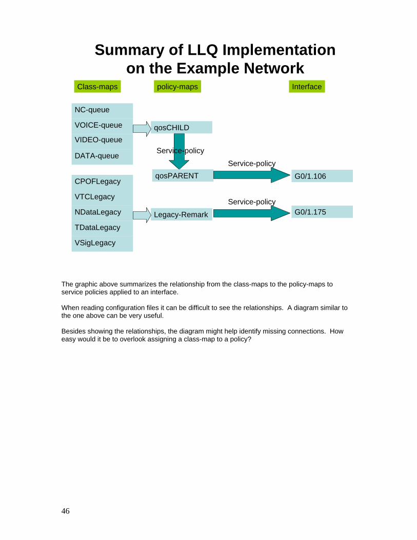
46
Summary of LLQ Implementation on the Example Network
CPOFLegacy
VSigLegacy
NDataLegacy
TDataLegacy
VTCLegacy
VIDEO-queue
DATA-queue
NC-queue
VOICE-queue qosCHILD
Legacy-Remark
qosPARENT
Class-maps policy-maps
Service-policy
Interface
G0/1.106
G0/1.175
Service-policy
Service-policy
The graphic above summarizes the relationship from the class-maps to the policy-maps to service policies applied to an interface. When reading configuration files it can be difficult to see the relationships. A diagram similar to the one above can be very useful. Besides showing the relationships, the diagram might help identify missing connections. How easy would it be to overlook assigning a class-map to a policy?

47
Example Network QoS
SIPR
NIPR
X
LLQ
Call-Signaling
Time Sensitive
Collaboration
Best Effort
PQ
CBWFQ
FirstinFirst O
ut (FIFO)
InterfaceScheduler
Network Control
Transit Data
Classifier
Queuing/Shaping
Marker
Congestion Management
Congestion Avoidance
Marking / ClassificationNIPR Data
The diagram above depicts the elements of QoS found within the example network. In this lesson, QoS was applied to the colorless router. Consistent QoS must also be applied to other devices in the network to ensure the network handles traffic as desired.

Insert Tab #6 Here

Access Control Lists Inc 1b

2

3
Why Use Access Lists
? Access List 10deny 148.43.200.1deny tcp eq 20permit any any
-Manage IP traffic as network access grows.-Filter packets as they pass through the router.
The earliest routed networks connected a modest amount of LANs and hosts. As the router connections increase to legacy and outside networks, and with the increased use of the Internet, there will be new challenges to control access. Network administrators face the following dilemma: how to deny unwanted connections while allowing appropriate access. Although other tools such as passwords, callback equipment, and physical security devices are helpful, they often lack the flexible and specific controls most administrators prefer. Access lists offer another powerful tool for network control. These lists add the flexibility to filter the packet flow in or out router interfaces. Such control can help limit network traffic and restrict network use by certain users or devices.

4
Hierarchical Model
CORE
DISTRIBUTION
ACCESS
Cisco Switches
Cisco Routers
In the new campus model, traffic patterns dictate the grouping and resulting placement of the services required by the end user. To properly build an internetwork that can view and address traffic pattern (user) requirements, the three-layer hierarchical model is organized as follows: • Access layer • Distribution layer • Core layer The access layer of the network is the point at which end users are connected to the network. This is why it is sometimes referred to as the desktop layer. Users and the resources they need to access most are locally available. Traffic to and from local resources is confined between the resources, switches and end users. Multiple “groups” of users and their resources exist at the access layer. The distribution layer of the network, also referred to as the workgroup layer, marks the point between the access layer and the main “motorway” of the internetwork, called the core. The primary function of this layer is to perform potentially “expensive” packet manipulations such as routing, filtering, and WAN access. The distribution layer can be summarized as the layer that provides “policy-based connectivity” because it determines if and how packets can access the core or backbone. The distribution layer determines the five fastest ways for a user request, such as file server access, to be forwarded to the server. Once the distribution layer decides the path, it forwards the request to the core layer. The core layer then quickly transports the request, using the instructions from the distribution layer. The sole purpose of the core layer of the network is to switch traffic as fast as possible. Typically, the traffic being transported is to and from services that are common to a majority of users. These services are referred to as enterprise services. Examples of enterprise services would be email,

5
Internet access, or video conferencing. When a user must have access to enterprise services, the user’s request is processed at the distribution layer. The distribution layer devices then forward the user requests to the core, or backbone. The backbone simply provides quick transport to the desired enterprise service. If and how a packet can be transported through the core is the role of the distribution layer.

6
Access List Applications
- Permit or deny packets moving through the router.- Permit or deny vty access to or from the router.- Permit or deny SNMP access to the router.- Permit or deny routing information.- Identify traffic for another application (ex. QoS)
Packet filtering helps control packet movement through the network. Such control can help limit network traffic and restrict network use by certain users or devices. To permit or deny packets from crossing specified router interfaces, Cisco provides access lists. An IP access list is a sequential list of permit and deny conditions that apply to IP addresses or upper-layer IP protocols. Access lists filter traffic going through the router but they do not filter traffic originated from the router. Access lists can also be applied to the vty ports of the router to permit or deny Telnet traffic into or out of the router’s vty ports. You can use IP access lists to establish a finer granularity of control when differentiating traffic into priority and custom queues. An access list can also be used to identify “interesting” traffic that serves to trigger dialing in dial-on-demand routing (DDR). Access lists are also a fundamental component of route maps, which filter and in some cases alter the attributes within a routing protocol update.

7
StandardSimple address specifications.Generally permits or denies entire protocol suite.
ExtendedMore complex address specifications.Generally permits or denies specific protocols.
What Are Access Lists?
OptionalDialer
OutgoingPacket
F0/0
S0/0Incoming
Packet
Access List Processes
Permit?Source
and Destination
Protocol
Access lists are optional mechanisms in Cisco IOS software that can be configured to filter or test packets to determine whether to forward them toward their destination or to discard them. How access lists operate is the subject of the next several pages. There are two general types of access lists: Standard access lists—Standard access lists for IP check the source address of packets that could be routed. The result permits or denies output for an entire protocol suite, based on the source network/subnet/host IP address. Extended access lists—Extended IP access lists check for both source and destination packet addresses. They can also check for specific protocols, port numbers, and other parameters, which allow administrators more flexibility in describing what checking the access list will do. Access lists may be applied as: Inbound access lists—Incoming packets are processed before being routed to an outbound interface. An input access list is efficient because it saves the overhead of routing lookups if the packet is to be discarded because it is denied by the filtering tests. If the packet is permitted by the tests, it is then processed for routing. Outbound access lists—Incoming packets are routed to the outbound interface and then processed through the outbound access lists. Access lists express the set of rules that give added control for packets that enter inbound interfaces, packets that relay through the router, and packets that exit outbound interfaces of the router. Access lists do not act on packets that originate from the router itself. Instead, access lists are statements that specify conditions on how the router will handle the traffic flow through specified interfaces. Access lists give added control for processing the specific packets in a unique way.

8
Access List Tests
MatchFirstTest
Packet to interface
Deny
Deny
Permit
Permit
MatchSecond
Test
Destination Interface
No
Packet Discard Bucket
No MatchAny TestDENY ALL
No
Top Down Processing
Access list statements operate in sequential, logical order. They evaluate packets from the top down, one statement at a time. If a packet header and an access list statement match, the rest of the statements in the list are skipped and the packet is permitted or denied as specified in the matched statement. If a packet header does not match an access list statement, the packet will then be tested against the next statement in the list. This matching process continues until the end of the list is reached. A final implied statement covers all packets for which conditions did not test true. This final test condition matches all other packets and results in a deny. Instead of proceeding in or out an interface, all these remaining packets are dropped. This final statement is often referred to as the “implicit deny any” at the end of every access list. Because of the implicit deny any, an access list should have at least one permit statement in it; otherwise, the access list will block all traffic. An access list can be applied to multiple interfaces. However, there can be only one access list per protocol, per direction, per interface.

9
How Access Lists Work
Y Y
Y
Y
Y
N
N
N
N
N
Unwanted PacketsNotify Sender
inboundinterface
packet
outboundinterface
packet
packet
As a packet enters an interface, the router checks to see whether the incoming interface is grouped to an access list. If not, the packet can be sent on to the routing process. If an access list exists, the packet will be processed from the top to the bottom of the list to determine whether it should be permitted or denied. If denied the packet is discarded. If permitted the packet continues on to the routing process. Next, the router checks to see whether it is routable by checking the routing table. If not routable, the packet will be dropped. Next, the router checks to see whether the destination interface is grouped to an access list. If not, the packet can be sent to the output buffer. For example: a. If it will use S0, which has not been grouped to an outbound access list, the packet is sent S0 directly. b. If it will use E0, which has been grouped to an outbound access list, before the packet can be sent out on E0, it is tested by a combination of access list statements associated with that interface. Based on the access list tests, the packet can be permitted or denied. For outbound lists, permit means send it to the output buffer; deny means discard the packet. For inbound lists, permit means continue to process the packet after receiving it on an inbound interface. Deny means discard the packet. When discarding packets, some protocols return a special packet to notify the sender that the destination is unreachable.

10
Configuration Guidelines
• Access list numbers indicate which protocol is filtered
• One access list per interface, per protocol, per direction
• Most restrictive statements should be at the top of the list
• There is a implicit deny any as the last access list test-every list should have at least one permit
• Create access lists before applying them to an interface
• Access list filter traffic going through the router; they do notapply to traffic originated from the router
Following these general principles, helps ensure the access lists you create have the intended results: 1. Only use the numbers from the assigned range for the protocol and type of list you are creating. 2. Only one access list per protocol, per direction, per interface is allowed. Multiple access lists are permitted per interface, but each must be for a different protocol. 3. Top-down processing • Organize your access list so that more specific references in a network or subnet appear before more general ones. Place more frequently occurring conditions before less frequent conditions. • Subsequent additions are always added to the end of the access list. • You cannot selectively add or remove lines when using numbered access lists, however, you can when using named IP access lists (a Cisco IOS Release 11.2 feature). With named IP access lists, additions are still added to the end of the access list. 4. Implicit deny all • Unless you end your access list with an explicit permit any, it will deny by default all traffic that fails to match any of the access list lines. • Every access list should have at least one permit statement. Otherwise, all traffic will be denied. 5. Create the access list before applying it to an interface. An interface with an empty access list applied to it allows (permits) all traffic. 6. Access lists only filter traffic going through the router. They do not filter traffic originated from the router.

11
Number Range/Identifier
IP 1-99, 1300-1999100-199, 2000-2699Named (Cisco IOS 11.2 and later)
How to Identify Access Lists
800-899900-9991000-1099Named (Cisco IOS 11.2. F and later)
StandardExtendedSAP filters
StandardExtended
Access List Type
600-699
IPX
AppleTalk
- Standard IP access lists (1-99, 1300-1999) test conditions of all IP packets from the source address
- Extended access lists (100-199, 2000-2699) can test conditions of source and destination ports
Access lists can control most protocols on a Cisco router. The figure shows the protocols and number ranges of the access list types for IP and IPX. IPX access lists are covered in the “Configuring Novell IPX” chapter of this course. An administrator enters a number in the protocol number range as the first argument of the global access list statement. The router identifies which access list software to use based on this numbered entry. Access list test conditions follow as arguments. These arguments specify test according to the rules of the given protocol suite. The test conditions for an access list vary by protocol. Many access lists are possible for a protocol. Select a different number from the protocol number range for each new access list; however, the administrator can specify only one access list per protocol, per direction, per interface. Specifying an access list number from 1 to 99, 1300 to 1999 instructs the router to accept standard IP access list statements. Specifying an access list number from 100 to 199, 2000 to 2699 instructs the router to accept extended IP access list statements.

12
Testing Packets w/ Standard Access Lists
Segment(for example, TCP header)
DataPacket(IP header)
Frame Header(for example, HDLC)
SourceAddress
Useaccess
list statements1-99, 1300-1999
Deny Permit
An Example from a TCP/IP Packet
Standard access lists only examine source address

13
Testing Packet w/ Extended Access lists
Segment(for example, TCP header)
DataPacket(IP header)
Frame Header(for example, HDLC)
DestinationAddress
SourceAddress
Protocol
PortNumber
Useaccess
list statements100-199,2000-2699
to test thepacket Deny Permit
Extended access lists offer greater flexibility
For TCP/IP packet filtering, Cisco IOS IP access lists check the packet and upper-layer headers for:
• Source IP addresses using standard access lists. Standard access lists are identified with a number in the range 1 to 99.
• Destination and source IP address, specific protocols, and TCP or UDP port numbers using extended access lists. Extended access lists are identified with a number in the range 100 to 199.
For all of these IP access lists, after a packet is checked for a match with the access list statement, it can be denied or permitted to use an interface in the access group

14
• 0 means check corresponding bit value• 1 means ignore value of corresponding bit
do not check address (ignore bits in octet)
=0 0 1 1 1 1 1 1
128 64 32 16 8 4 2 1
=0 0 0 0 0 0 0 0
=0 0 0 0 1 1 1 1
=1 1 1 1 1 1 0 0
=1 1 1 1 1 1 1 1
Octet bit position and address value for bit
ignore last 6 address bits
check all address bits(match all)
ignore last 4 address bits
check last 2 address bits
Examples
How to Use Wildcard Mask Bits
Address filtering occurs using access list address wildcard masking to identify how to check or ignore corresponding IP address bits. Wildcard masking for IP address bits uses the number 1 and the number 0 to identify how to treat the corresponding IP address bits. • A wildcard mask bit 0 means “check the corresponding bit value”. • A wildcard mask bit 1 means “do not check (ignore) that corresponding bit value.” This type of mask is sometimes referred to as an “inverted mask”. By carefully setting wildcard masks, an administrator can select single or several IP addresses for permit or deny tests. Refer to the example in the figure. NOTE: Wildcard masking for access lists operates differently from an IP subnet mask. A 0 (zero) in a bit position of the access list mask indicates that the corresponding bit in the address must be checked; a 1 (one) in a bit position of the access list mask indicates the corresponding bit in the address is not “interesting” and can be ignored.

15
• Example 172.30.16.29 0.0.0.0 checks all the address bits
• Abbreviate the wildcard using the IP address preceded by the keyword host or simply the IP in standard lists
Test conditions: Check all the address bits (match all)
172.30.16.29
0.0.0.0(check all bits)
An IP host address, for example:
Wildcard mask:
Matching a Specific IP Host Address
You have seen how the zero and one bits in an access list wildcard mask cause the access list to either check or ignore the corresponding bit in the IP address. In the figure, this wildcard masking process is applied in an example. Consider a network administrator who wants to specify that a specific IP host address will be denied in an access list test. To indicate a host IP address, the administrator would enter the full address—for example, 172.30.16.29; then to indicate that the access list should check all the bits in the address, the corresponding wildcard mask bits for this address would be all zeros, that is, 0.0.0.0. Working with decimal representations of binary wildcard mask bits can be tedious. For the most common uses of wildcard masking, you can use abbreviation words. These abbreviation words reduce how many numbers an administrator will be required to enter while configuring address test conditions. One example where you can use an abbreviation instead of a long wildcard mask string is when you want to match a host address. The administrator can use the abbreviation host to communicate this same test condition to Cisco IOS access list software. In the example, instead of typing 172.30.16.29 0.0.0.0, the administrator can use the string host 172/30.16.29.

16
• Accept any address: 0.0.0.0 255.255.255.255
• Abbreviate the expression using the keyword any
Test conditions: Ignore all the address bits (match any)
0.0.0.0
255.255.255.255(ignore all)
Any IP address
Wildcard mask:
Matching Any IP Address
A second common condition where Cisco IOS software will permit an abbreviation term in the access list wildcard mask is when the administrator wants to match all the bits of any IP address. Consider a network administrator who wants to specify that any destination address will be permitted in an access list test. To indicate any IP address, the administrator would enter 0.0.0.0; then to indicate that the access list should ignore (allow without checking) any value, the corresponding wildcard mask bits for this address would be all ones (255.255.255.255). The administrator can use the abbreviation any to communicate this same test condition to Cisco IOS access list software. Instead of typing 0.0.0.0 255.255.255.255, the administrator can use the work any by itself as the keyword.

17
Wildcard Bits to Match IP Subnets
Test for IP subnets 172.30.16.0/24 to 172.30.31.0/24172.30.16.0 0.0.15.255
Address Wildcard Mask
0 0 0 1 0 0 0 00 0 0 0 1 1 1 1
match wildcard bits0 0 0 1 0 0 0 0 = 16 0 0 0 1 0 0 0 1 = 170 0 0 1 0 0 1 0 = 18. . . . . . . . . . . . . . . . . .
0 0 0 1 1 1 1 1 = 31
Wildcard mask:
172.30.16.0
An administrator wants to test a range of IP subnets that will be permitted or denied. Assume the IP address is a Class B address (the first two octets are the network number) with eight bits of subnetting (the third octet is for subnets). The administrator wants to use the IP wildcard masking bits to match subnets 172.30.16.0/24 to 172.30.31.0/24. First, the wildcard mask will check the first two octets (172.30) using corresponding zero bits in the wildcard mask. Because there is no interest in an individual host, the wildcard mask will ignore the final octet by using corresponding one bits in the wildcard mask (The final octet of the wildcard mask is 255 in decimal for example). In the third octet, where the subnet address occurs, the wildcard mask will check that the bit position for the binary 16 is on and all the higher bits are off using corresponding zero bits in the wildcard mask. For the final (low-end) four bits in this octet, the wildcard mask will indicate that the bits can be ignored. In these positions, the address value can be binary 0 or binary 1. Thus, the wildcard mask matches subnet 16, 17, 18, and so on up to subnet 31. The wildcard mask will not match any other subnets. In this example, the address 172.30.16.0 with the wildcard mask 0.0.15.255 matches subnets 172.30.16.0/24 to 172.30.31.0/24.

18
Contiguous Wildcard Masks
router (config) # access-list 1 deny 172.30.16.192 0.0.0.63
Range = 172.30.16.192 – 172.30.16.255Tested addresses:
can’t change
0. 0. 0. 63
matchAddress: 1 1 0 0 0 0 0 0 = 192Mask: 0 0 1 1 1 1 1 1 = 63
172.30.16.
router (config) # access-list 1 permit any
Non-contiguous Wildcard Masks
0. 0. 0. 33
match
172.30.16.
Address: 1 1 0 0 0 0 0 0 = 192Mask: 0 0 1 0 0 0 0 1 = 33
Range = 172.30.16.192 172.30.16.224172.30.16.193 172.30.16.225
Tested addresses:
router (config) # access-list 1 deny 172.30.16.192 0.0.0.33 router (config) # access-list 1 permit 0.0.0.0 255.255.255.255

19
Access-list [1-99,1300-1999] {permit/deny} s.s.s.s w.w.w.w
s.s.s.s = source ip (single host or Network)w.w.w.w = wildcard mask
Standard ACL Syntax
The access-list command creates an entry in a standard IP traffic filter list. Access-list Command Description Access-list-number Identifies the list to which the entry belongs; a number from 1 to 99. permit | deny Indicates whether this entry allows or blocks traffic from the
specified address.
source Identifies source IP address. source-mask Identifies which bits in the address field are matched. The default
mask is 0.0.0.0 (match all bits). NOTE: To remove an IP access list from an interface, first enter the no ip access-group access-list-number command on the interface, and then enter the global no access-list access-list-number command to remove the access list.

20
(config)#access-list 1 deny 148.43.200.136(config)#access-list 1 permit 148.43.200.0 0.0.0.7(config)#access-list 1 deny any
All ip addresses from the 148.43.200.0 network are permitted except 148.43.200.136
Standard ACL Example

21
(config)#line vty 0 4(config-line)access-class [ACL#] {in/out}
Routers have 5 vty linesSwitches have 16 vty linesDefault wildcard mask is 0.0.0.0Use the any keyword to replace the source address
Apply to vty Lines
Standard access lists are not typically applied to a physical interface. That job is usually reserved for extended access lists. The purpose of applying an access list to the VTY lines is to prevent unauthorized access via SSH or Telnet. To filter access to the VTY lines first configure a standard access list. Once the list is created, you enter the VTY lines using the following commands: (config)# Line VTY 0 4 (Switch 0 15) (config-Line)# access-class # {in/out} When applying to VTY lines apply the list using the access-class command. Specify which list by using its number and a direction either in or out.

22
(config)#access-list 99 permit 148.43.200.136(config)#access-list 99 permit 148.43.200.51(config)#access-list 99 deny any(config)#line vty 0 4(config-line)access-class 99 in
Virtual Terminal Line Access
In this example, only the IP addresses of 148.43.200.136 and 148.43.200.51 will be allowed access to the VTY lines.

23
1. Configure a standard access list to allow telnet access from your workstation and the instructors workstation while blocking everyone else.
2. Try to telnet to your router.
3. Have the instructor try to telnet to your router.
4. Have your neighbor try to telnet to your router.
5. Create and apply the ACL and retry.
VTY ACL Lab 1

24
Access-list [100-199,2000-2699] {permit/deny} {protocol} s.s.s.s w.w.w.w d.d.d.d w.w.w.w eq {port#}
Access-list [100-199,2000-2699] {permit/deny} ip any any
protocol = IP,TCP,UDP,ICMPs.s.s.s = source ip (single host or Network)d.d.d.d = destination ip (single host or Network)w.w.w.w = wildcard maskPort # = 0 – 65535 or service name
Extended ACL Syntax
The access-list command creates an entry to express a condition statement in a complex filter. The following table explains the syntax of the command as shown in the figure.
access-list command Description
access-list-number Identifies the list using a number in the range 100 to 199.
permit | deny Indicates whether this entry allows or blocks the specified address.
protocol IP, TCP, UDP, ICMP, GRE, IGRP
source and destination Identifies source and destination IP addresses
Source-wildcard and destination wildcard
Wildcard mask; 0s indicate positions that must match, 1s indicate “don’t care” positions.
operator port lt, gt, eq, neq, (less than, greater than, equal, not Equal), and a port number.
established Allows TCP traffic to pass if packet uses an established connection (for example, it has ACK bits set).
log Sends a logging message to the console.
NOTE: The syntax of the access-list command presented here is representational of the TCP protocol form. Not all parameters or options are given. For the complete syntax of all forms of the command, refer to the appropriate Cisco IOS documentation available on CD-ROM or at the CCO web site.

25
(config)#interface {interface}(config)#ip access-group {ACL#} [in/out]
1 ACL per direction per interface
Apply to an Interface
The ip access-group command links an existing extended access list to an interface. Only one access list per protocol, per direction, per interface is allowed. IP ACCESS-GROUP DESCRIPTION Access-list-number Indicates the number of the access list to be
linked to an interface. in-out Selects whether the access list is applied as an
input or output filter. If in or out is not specified, out is the default.

26
Extended Access List Example 1
172.16.3.0 172.16.4.0
172.16.3.2 172.16.4.13
Non-172.16.0.0
S0/0
F0/0 F0/1
Access-list 101 deny tcp 172.16.4.0 0.0.0.255 172.16.3.0 0.0.0.255 eq 21Access-list 101 deny tcp 172.16.4.0 0.0.0.255 172.16.3.0 0.0.0.255 eq 20Access-list 101 permit ip any any(implicit deny all)(Access-list 101 deny ip 0.0.0.0 255.255.255.255 0.0.0.0 255.255.255.255
Interface Fastethernet F0/0Ip access-group 101 out
-Deny FTP from subnet 172.16.4.0 to subnet 172.16.3.0 out of F/00-Permit all other traffic
In the example:
ACCESS-LIST COMMAND DESCRIPTION
101 deny tcp 172.16.4.0 0.0.0.255
Protocol type of TCP Source IP address and mask; the first three octets must match but ignore the last octet.
172.16.3.0 0.0.0.255 Destination IP address and mask; the first three octets must match, but ignore the last octet.
eq 20 | eq 21 Specifies standard FTP port numbers. IP ACCESS-GROUP 101 COMMAND
DESCRIPTION
out Links access list 101 to interface F0/0 as an output filter. The deny statements deny FTP traffic from subnet 172.16.4.0 to subnet 172.16.3.0. The permit statement allows all other IP traffic out interface F0/0.

27
Extended Access List Example 2
172.16.3.0 172.16.4.0
172.16.3.2 172.16.4.13
Non-172.16.0.0
S0/0
F0/0 F0/1
Access-list 101 deny tcp 172.16.4.0 0.0.0.255 172.16.3.0 0.0.0.255 eq 23Access-list 101 permit ip any any(implicit deny all)(Access-list 101 deny ip 0.0.0.0 255.255.255.255 0.0.0.0 255.255.255.255
Interface fastethernet 0/0Ip access-group 101 out
-Deny only Telnet from subnet 172.16.4.0 out of e0-Permit all other traffic

28
(config)#ip access-list standard {unique name}(config-std-nacl)#[permit/deny] {test parameters}
(config)#ip access-list extended {unique name}(config-exd-nacl)#[permit/deny] {test parameters}
Named ACL Syntax
This feature allows IP standard and extended access lists to be identified with an alphanumeric string (name) instead of the current numeric (1 to 199) representations with a numbered IP access list, an administrator wanting to alter an access list would first be required to delete the numbered access list then reconfigure it. Individual statements cannot be deleted. Named IP access lists allow you to delete, but not insert, individual entries from a specific access list. Deleting individual entries enables you to modify your access lists without deleting and then reconfiguring them. Use named IP access list when: • You want to intuitively identify access lists using an alphanumeric name. Consider the following before implementing named IP access lists: • Named IP access lists are not compatible with Cisco IOS releases prior to Release 11.2. • You cannot use the same name for multiple access lists. In addition, access lists of different types cannot have the same name. For example, it is illegal to specify a standard access control list named “George” and an extended access control list with the same name. NOTE: Most of the commonly used IP access list commands accept named IP access lists.

29
Access List Configuration Principles
- Order of access list statements is crucialRecommended: use a text editor on a TFTP server or use PC to cut and paste
- Top-down processingPlace more specific test statements first
- Reordering or removal of statementsUse no access-list number command to remove entire list – or –Modify numbered ACLs using named syntax
- Implicit deny allUnless access list ends with explicit permit any
The basic principles of access list configuration are given in the figure. • The order of access list statements is crucial to proper filtering. It is recommended to create and download your access list on a TFTP server using a text editor or to use a PC to cut and paste the access list into the router. • Access lists are processed from the top down. If you place more specific tests, and tests that will test true frequently, in the beginning of the access list you can reduce processing overhead. • Only named access lists allow removal, but not reordering, of individual statements from a list. If you wish to reorder or remove access list statements, you must remove the whole list and recreate it in the desired order or with the desired statements. • All access lists end with an implicit deny all statements.

30
Where to Place Access Lists
TOKENRINGTo0
F0/0
F0/0 F0/0
F0/0
F0/1
S0/0 S0/0
S0/1 S0/1
A
B C
D
Recommended:- Place extended access lists close to the source- Place standard access lists close to the destination
S1/1
S0/1
D
Access lists are used to control traffic by filtering and eliminating unwanted packets. Proper placement of an access list statement can reduce unnecessary traffic. Traffic that will be denied at a remote destination should not use network resources along the route to that destination. Suppose an enterprise’s policy aims at denying Token Ring traffic on Router A to the switched Ethernet LAN on Router D’s E1 port. At the same time, other traffic must be permitted. Several approaches can accomplish this policy. The recommended approach uses an extended access list. It specifies both source and destination addresses. Place this extended access list in Router A. Then, packets do not cross Router A’s Ethernet, do not cross the serial interfaces of Routers B and C, and do not enter Router D. Traffic with different source and destination addresses can still be permitted. Extended access lists should normally be placed as close as possible to the source of the traffic to be denied. Standard access lists do not specify destination addresses. The administrator would have to put the standard access list as near the destination as possible. For example, place an access list on E0 of Router D to prevent Token Ring traffic from Router A.

31
Commands to Verify Access Lists
- show ip interfaceWill show the access list applied to that interface
- show access-listsWill show all access lists on the router
- show access-lists {access-list number}Displays on the access list number you specify
- show {protocol} access-list {access-list number}Will show all access lists applied in that protocol. (Normally you would use IP)

32
1. Configure an extended access list to block web access from your workstation to the instructors workstation while permitting everyone else.
2. Try to web to the instructors laptop
3. Try to ping the instructors laptop
4. Create and apply the ACL and retry
Extended ACL Lab 3

33
ACL Statement Ordering
• Both named and numbered ACLs can be modified inline (IOS > 12.3)
• Use “show ip access-list x” to view ACL statements and line numbers
• Use “ip access-list x standard|extended” to enter ACL management context
• Statements can be added, modified or removed via line # reference
Beginning with IOS version 12.3, Cisco included the ability to modify named access lists, but numbered as well. Numbered access-lists can still be managed in the traditional manner of using the “no access-list x” statement, but best practice is that the numbered ACL should first be unapplied prior to modification. Being able to modify even numbered ACLs in place leads to fewer configuration errors – especially when modifications are done remotely. In the device configurations, the numbered access lists continue to appear in their traditional format. However, if they are to be modified in place, use the named access list command syntax. The following page shows a couple examples of numbered access-lists being modified in this manner. Existing statements are numbered in order by 10s (i.e. 10, 20, 30, etc.). To insert a statement, simply use any number between the two numbered statements. For example, to insert a statement between lines 20 & 30, use 21-29. Once these statements are created, they will show in the configurations in proper order and their reference numbers will display in the show commands. However, upon the reboot of the device, the statements will renumber in order by 10s.

34
ACL Statement Ordering Example 1
Show ip access-list 90
Standard IP access list 9010 permit 22.230.8.22420 permit 22.230.4.0, wildcard bits 0.0.0.31 log30 deny any log
Conf tip access-list standard 9015 deny 22.230.4.2025 permit 22.230.7.225
End
Show ip access-list 90
Standard IP access list 9025 permit 22.230.7.22510 permit 22.230.8.22415 deny 22.230.4.2020 permit 22.230.4.0, wildcard bits 0.0.0.31 log30 deny any log
ACL Statement Ordering Example 2
Show ip access-list IA_Allowed_SNMP_RO
Standard IP access list IP_Allowed_SNMP_RO10 permit 22.230.4.2020 permit 22.230.7.0, wildcard bits 0.0.0.31 log
Conf tip access-list standard IP_Allowed_SNMP_ROpermit 22.230.4.30 0.0.0.315 deny 22.230.4.20no 10
End
Show ip access-list IA_Allowed_SNMP_RO
Standard IP access list IP_Allowed_SNMP_RO5 deny 22.230.4.2020 permit 22.230.7.0, wildcard bits 0.0.0.31 log30 permit 22.230.4.0, wildcard bits 0.0.0.31

35
2ABC2: First digit is always 2 to set acceptable 2101-
2392 rangeA: Where the ACL is applied:
1 - JNN/Hub Tier 1/2 Router2 - JNN/Hub Tier 2 Router3 - Bn CP Tier 2 Router
WIN-T ACL Numbering

36
2ABCB: Distant end:
0 - UnTrusted Network1 - JNN/Hub Tier 1/2 Router2- JNN/Hub Tier 2 Router3 - Bn CP Tier 2 Router4 - Protected User Enclave5 - Unprotected User Enclave6 - Voice VLAN8 – FDD Plug & Play TOC Network9 - Mgt/Server Enclave
ACL Numbering (1)
2ABCC: Direction of ACL (from point of presence of
Field A)1 - Inbound2 - OutboundX - Inbound & Outbound
ACL Numbering (2)

37
The router administrator will ensure ICMP unreachable notifications, mask replies, and redirects are disabled on all external interfaces of the premise router.
access-list 2101 deny icmp any any echo-reply logaccess-list 2101 deny icmp any any time-exceeded logaccess-list 2101 deny icmp any any unreachable log
ICMP Control
The IAO/NSO will ensure that the premise router is acting as an NTP server for only internal clients.
access-list 2101 deny udp any any eq ntp logaccess-list 2102 permit udp any host<A.B.C.D> eq ntpaccess-list 2102 deny udp any any eq ntp log
NTP Control

38
Inc 1b ACL Additions (1)
• Colorless Router– Numbered Management ACLs changed to named
• 90 = IA_Allowed_SNMP_RO• 95 = IA_Allowed_SNMP_RW• 99 = IA_Allowed_VTY_IN
– IPV6 ACLs• ipv6 “no-ipv6-packets”• Ipv6 “inbound-to-enclave”
The Increment 1b package will include named ACLs for use in limiting access to Cisco network devices. This marks a change from the previous incarnations of the WIN-T system, which used standard, numbered ACLS. The colorless router also includes a new access list to prevent actual IPv6 traffic from traversing through the router. Tat this stage the IPv6 protocol is enabled only on the colorless router and only to allow the OSPF version 3 routing protocol to function properly. As with any other router, any traffic not required or expected to transit the network device should be filtered.

39
Inc 1b ACL Additions (2)
• SIPR/NIPR Enclave Routers– TACLANE Blocking
• IA_ACL_JNN_S_N_TACLANE
• Prevents existing TACLANE tunnel formation over colorless enclave
• Applied to VLAN 6 (Plug and Play TOC)– Named SNMP & Telnet ACLs
ip access-list extended IA_ACL_JNN_S_N_TACLANEdeny ip 172.19.0.0 0.0.255.255 172.19.0.0 0.0.255.255deny ip 172.20.0.0 0.0.255.255 172.20.0.0 0.0.255.255permit ip any any
The increment 1b package also includes an access list designed to prevent the existing TACLANE network from utilizing the NCW network as a transit path. This is done because the only purpose of the colorless suite is to allow access into the Increment 2 network for an Increment 1 and earlier system. As with the colorless router itself, the SIPR and NIPR routers include named access lists for device management access.