Embed Size (px)
Citation preview
1
Fireware XTM TrainingStudent Guide
Branch Office VPN TunnelsCreating IPSec VPNs in Fireware XTM 11.x
This training is for:
Introduction
About Instructor NotesInstructor Notes do not appear in the Student Guide. You can quickly find them by looking for the black vertical bar on the side of the page. The “side note” below appears in the Student Guide and the Instructor Guide.
What You Will LearnIn this course, you learn how to make branch office virtual private networks (BOVPNs) between Firebox X or WatchGuard XTM devices with Fireware XTM version 11.x, when one or both devices have multiple connections to the Internet. You learn how to make these VPNs manually and with the WatchGuard Management Server. You also learn how VPN failover works.
ExerciseAbout Side NotesSide notes are extra information that is not necessary to understand the training. They might be configuration or troubleshooting tips, or extra technical information.
This course includes a step-by-step exercise to show you how to make VPNs in a multi-WAN environment. It also illustrates a use case that might apply in your organization.
Before you begin the exercise, be sure to read the section “Before You Begin,” on page 40. This section has a list of the equipment and software you need to do the exercise, and gives you basic information about how to prepare your device.
What BOVPNs Can Do For YouA BOVPN enables computers at one office to securely transmit private data through an untrusted public network to computers at another office. The BOVPN provides these benefits:
• Privacy or confidentiality of the data — The VPN uses encryption to guarantee that traffic between the two offices is secret. An attacker that intercepts the traffic cannot understand it.
• Data integrity — The VPN guarantees that the data that passes through it has not been altered in transit.
• Data authentication — The VPN guarantees that data that passes through the tunnel actually comes from one of the two endpoints of the VPN, and not from some attacker on the Internet.
Devices Firebox X Edge e-Series / Firebox X Core e-Series / Firebox X Peak e-Series / WatchGuard XTM 2 Series /WatchGuard XTM 5 Series / WatchGuard XTM 8 Series / WatchGuard XTM 1050
Device OS versions Fireware XTM v11.x with a Pro Upgrade
Management Software versions WatchGuard System Manager v11.x
Category VPN, Multi-WAN
2 WatchGuard Fireware XTM Training
• Direct private IP address to private IP address communication — The computers at the two offices communicate as if they were not behind devices with Network Address Translation (NAT). The data “tunnels” through NAT to give a transparent connection from one device to the other.
Related Courseware and InformationWatchGuard Training: Fireware XTM Multi-WAN Methods
This course shows you how Fireware XTM handles outgoing, non-IPSec traffic with each of the four different multi-WAN modes of operation:
- Round-robin - Failover - Interface Overflow - Routing Table
Frequently Asked QuestionsThe WatchGuard Knowledge Base provides articles that can help expand your knowledge. For example, the Knowledge Base has articles about:
- BOVPN Interoperability - Use NAT through a BOVPN tunnel - Set up a default route to send all Internet-bound traffic through a BOVPN - Use tunnel switching to route VPN traffic between two BOVPN tunnels - Use traffic management with BOVPN tunnels - Improve availability of your VPN connection - Configure VPN failover
Search the Knowledge Base at http://watchguard.custhelp.com.
What You Should Know
How Branch Office VPNs work A Branch Office VPN tunnel (BOVPN) is a method for two networks to send data through an untrusted network (typically, the Internet) using an encrypted, authenticated connection.
In this training, the gateway device at each location is a WatchGuard Firebox or XTM device, but your Firebox or XTM device can make an IPSec VPN tunnel to any device that implements the IPSec standards.
One gateway device at each location does the IPSec processing for all the computers behind the gateway device. The computers at each location do not need any special software and they are not aware that IPSec processing takes place.
The Firebox or XTM device looks at traffic that comes from and goes to computers on its protected networks. It knows what traffic to encrypt and send to the other
What You Should Know
3
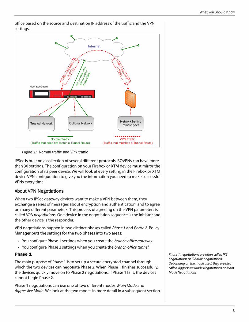
office based on the source and destination IP address of the traffic and the VPN settings.
Figure 1: Normal traffic and VPN traffic
IPSec is built on a collection of several different protocols. BOVPNs can have more than 30 settings. The configuration on your Firebox or XTM device must mirror the configuration of its peer device. We will look at every setting in the Firebox or XTM device VPN configuration to give you the information you need to make successful VPNs every time.
About VPN NegotiationsWhen two IPSec gateway devices want to make a VPN between them, they exchange a series of messages about encryption and authentication, and to agree on many different parameters. This process of agreeing on the VPN parameters is called VPN negotiations. One device in the negotiation sequence is the initiator and the other device is the responder.
VPN negotiations happen in two distinct phases called Phase 1 and Phase 2. Policy Manager puts the settings for the two phases into two areas:
• You configure Phase 1 settings when you create the branch office gateway.
• You configure Phase 2 settings when you create the branch office tunnel.
Phase 1 negotiations are often called IKE negotiations or ISAKMP negotiations. Depending on the mode used, they are also called Aggressive Mode Negotiations or Main Mode Negotiations.
Phase 1
The main purpose of Phase 1 is to set up a secure encrypted channel through which the two devices can negotiate Phase 2. When Phase 1 finishes successfully, the devices quickly move on to Phase 2 negotiations. If Phase 1 fails, the devices cannot begin Phase 2.
Phase 1 negotiations can use one of two different modes: Main Mode and Aggressive Mode. We look at the two modes in more detail in a subsequent section.
4 WatchGuard Fireware XTM Training
Phase 2 negotiations are often called IPSec negotiations or Quick Mode negotiations.
Phase 2
The purpose of Phase 2 negotiations is for the two peers to agree on a set of parameters that define what traffic can go over the VPN, and how to encrypt and authenticate the traffic. The resulting agreement is called a Security Association.
About the gateway name and the tunnel name
You assign names to each gateway and tunnel. These names are for your use only; the Firebox or XTM device does not send them to the remote peer. Use a name that helps you identify the remote device for the gateway. For the examples in the next sections, we call the gateway RemotePeer, and we call the tunnel BranchOfficeTunnel.
In the next section we introduce some terms you might see in the training. Then, we look at all the different parameters that the two VPN devices agree upon during the VPN negotiations. Finally, we show all steps required to set up a VPN between two Firebox or XTM devices.
Terms and DefinitionsUse this list as a reference for the rest of the training course.
IPSec is built on a collection of protocols and algorithms that include: Encryption algorithms: – DES – 3DES – AES (128, 192, or 256-bit key length) Authentication algorithms: – HMAC-SHA1 – HMAC-MD5Internet Key Exchange (IKE) protocolOakley key determination protocolDiffie-Hellman key exchange algorithmInternet Security Association and Key Management Protocol (ISAKMP)Authentication Header (AH)Encapsulating Security Payload (ESP)
AESAdvanced Encryption Standard.
This encryption algorithm is the strongest available. Fireware XTM can use AES with encryption keys of length 128, 192, or 256 bits.
Aggressive ModeOne of the two modes that Phase 1 VPN negotiations can use.
It uses a total of three messages between the two IKE peers. Aggressive Mode does not give protection for the identities of the two IKE peers.
AHAuthentication Header.
Defined in RFC 2402, AH provides security by adding authentication information to the IP datagram. Because AH does not provide encryption, it is not typically used for VPNs.
The Internet Assigned Numbers Authority (IANA) assigned AH the IP protocol number 51. (Compare to TCP which is IP protocol 6, and UDP which is IP protocol 17.)
DESData Encryption Standard.
An older encryption algorithm that is still in wide use. It uses an encryption key that is 56 bits long.
3DESTriple-DES or three-DES.
An encryption algorithm based on DES. The DES encryption algorithm is applied to a data set once, and then the result is encrypted again with DES. Finally, this result is encrypted one more time with DES.
What You Should Know
5
Diffie-Hellman group (DH group)A group of integers used for the Diffie-Hellman key exchange.
The Diffie-Hellman group is also called the DH group or key group. Fireware XTM can use DH groups 1, 2, and 5. The larger key groups give larger integers to use in the exchange, which provides stronger security.
Diffie-Hellman key exchangeA method of making a shared encryption key available to two entities without actually exchanging the key.
The encryption key for the two devices is used as a symmetric key for encrypting data. The security of the resulting encryption key comes from the extreme difficulty of solving certain mathematical problems in reverse (the discrete logarithm problem). Only the two parties involved in the DH key exchange can deduce the shared key, and the key is never sent over the wire.
ESPEncapsulating Security Payload.
Defined in RFC 2406, ESP provides confidentiality and integrity of data. ESP takes the original data payload of a data packet and replaces it with encrypted data. It adds integrity checks to be sure that the data is not altered in transit, and that the data came from the proper source.
The Internet Assigned Numbers Authority (IANA) assigns a number to each protocol. For ESP, the IP protocol number is 50. For TCP, the IP protocol number is 6. For UDP, the IP protocol number is 17.
HashA mathematical transform applied to a set of data.
This transform takes a string of bits as input and produces an output called the hash or hash value. (The hash value is normally much smaller than the original data input.) A hash is generally a one-way function. It is not possible to find the original input if the only data you have is the hash. There are different hash algorithms, but for any given input and any given algorithm, the hash value is always the same.
Computing hash values to compare data sets is much more efficient than exchanging and comparing the actual raw data. This is because the hash is much smaller than the raw data.
If two entities each have a set of data and they want to see if they are the same data set without actually exchanging the data, they can both compute the hash of their own data set using the same hash algorithm. Next, they exchange the hash values that they each compute and compare them. If the two hash values match, then the input data is the same on each side. If the hash values do not match, then the data sets are not identical.VPN traffic uses a variation of the hash idea called a Hashed Message Authentication Code or HMAC (sometimes also called a Keyed HMAC). Similar to the normal use of hash functions, each VPN peer computes hashes of data to guarantee the data’s integrity. In addition, each side mixes the data with a secret key before computing the hash. This guarantees the authenticity of the data; each side knows that the data came from the authorized peer and not an imposter or attacker.
IKEInternet Key Exchange.
Defined in RFC 2409, IKE specifies methods to obtain authenticated keying material for use with ISAKMP.
6 WatchGuard Fireware XTM Training
IKE peerThe entity that your Firebox or XTM device uses to make a VPN.
The IKE peer is typically another IPSec device such as another firewall.
IPSecA collection of cryptography-based services and security protocols to protect communication between entities that send traffic through an untrusted network (such as the public Internet).
ISAKMPInternet Security Association and Key Management Protocol.
Defined in RFC 2408, ISAKMP provides a framework for authenticating a communicating peer, for key generation techniques, and for managing (negotiating, forming and destroying) Security Associations. IKE and Oakley operate within this framework.
Key expiration
Phase 1 keys usually expire based on an amount of time, but expiration can also be based on the amount of data exchanged. Phase 2 keys usually expire based on an amount of time or an amount of data sent. The first event that happens (time elapsed or amount of data sent) causes the key to expire. If you set either the time or data limit to zero, the Firebox or XTM device disregards that limit. If you set both to zero, the key never expires.
Phase 1 and Phase 2 session and encryption keys change periodically.
This prevents an attacker from getting access to a large data set using the same encryption keys. When a key must change, the appliance declares the current key no longer valid.
Main ModeOne of the two modes that Phase 1 VPN negotiations can use.
It uses a total of six messages between the two IKE peers. Main Mode gives protection to the identities of the two IKE peers.
MD5Message Digest 5.
This is a hash algorithm. The type of MD5 algorithm used by IPSec provides data integrity (a guarantee that the data has not changed in transit) as well as authentication of the data (a guarantee that the data came from the proper source). MD5 is not considered as strong a hash algorithm as SHA-1.
OakleyThe Oakley Key Determination Protocol.
This is a protocol for two parties to agree on a secret key. RFC 2412 describes the protocol named Oakley, by which two authenticated parties can agree on secure and secret keying material. The basic mechanism is the Diffie-Hellman key exchange algorithm.
PFSPerfect Forward Secrecy.
A guarantee that keying material used to generate one encryption key is not used to generate a new encryption key. If one key is compromised, it gives the attacker no information about subsequent encryption keys.
Quick ModeThe mode that Phase 2 VPN negotiations use.
Quick Mode is the only mode that Phase 2 uses. The two IKE peers exchange three messages to complete Quick Mode.
What You Should Know
7
Replay An attack that consists of capturing data packets sent from one IKE peer to another, and then sending them to the recipient again.
The attacker can get information about the IPSec implementation from the responses it gets from the recipient. Fireware XTM uses the sequence numbers in ESP packets to reject duplicate packets and old packets, to protect against replay attacks.
SASecurity Association.
This is a contract between two IPSec endpoints. The SA is an abstract object that contains all the information necessary for two entities to exchange data securely.
SHA-1Secure Hash Algorithm 1.
A type of hash algorithm called a cryptographic hash function. It provides data integrity (a guarantee that the data has not changed in transit) as well as authentication of the data (a guarantee that the data came from the proper source). SHA-1 is considered a stronger hash algorithm than MD5.
SPISecurity Parameters Index.
This is the 32-bit number that identifies an IPSec SA. The SPI number is an identifier in the header of every IPSec data packet. This number tells the receiving gateway device to which IPSec data flow the packet belongs. The SPI number is not bidirectional. Each device keeps an SPI number for traffic it sends (outgoing SPI) and an SPI number for traffic it receives (incoming SPI).
Traffic selector
Sometimes traffic selectors have additional limits based on source and destination ports. Because you control traffic in Fireware XTM with firewall policies, this type of limitation is usually not necessary.
The configuration parameter that tells the gateway device what traffic can pass through the VPN.
Traffic selectors in Fireware XTM are called tunnel routes. Traffic selectors consist of source IP addresses and destination IP addresses. Each peer has a reverse match of the other peer’s traffic selectors. If one peer has subnet A as the local part of its traffic selector and subnet B as the remote part of its traffic selector, then the other peer has subnet B as local and subnet A as remote.
When a data packet comes in from a host on an internal network, Fireware XTM checks to see if the source and destination IP addresses of the packet match a traffic selector. If they do, and if there is a policy to allow the traffic, then Fireware XTM encapsulates the data packet in IPSec and sends it to the IPSec peer.
TunnelThe virtual path between two locations on the Internet that a VPN between them.
This virtual path is called a tunnel because data packets are encapsulated inside ESP headers and trailers, and inside a new IP header. Thus, two computers behind two IKE gateways can send packets to private IP addresses, effectively “tunneling” through the public Internet.
8 WatchGuard Fireware XTM Training
Some of your students may be familiar with the very rigid order of VPN negotiations: Certain information must be in the first message and cannot be in any other message. Certain information must be in the second packet exchange, and cannot be in any other message, and so on.
In the subsequent sections, the information is not presented in the same order as the negotiation messages. The steps follow the order in which the Firebox or XTM device administrator completes the different dialog boxes.
This enables you to move easily from one dialog box to the next and explain the purpose of each one.
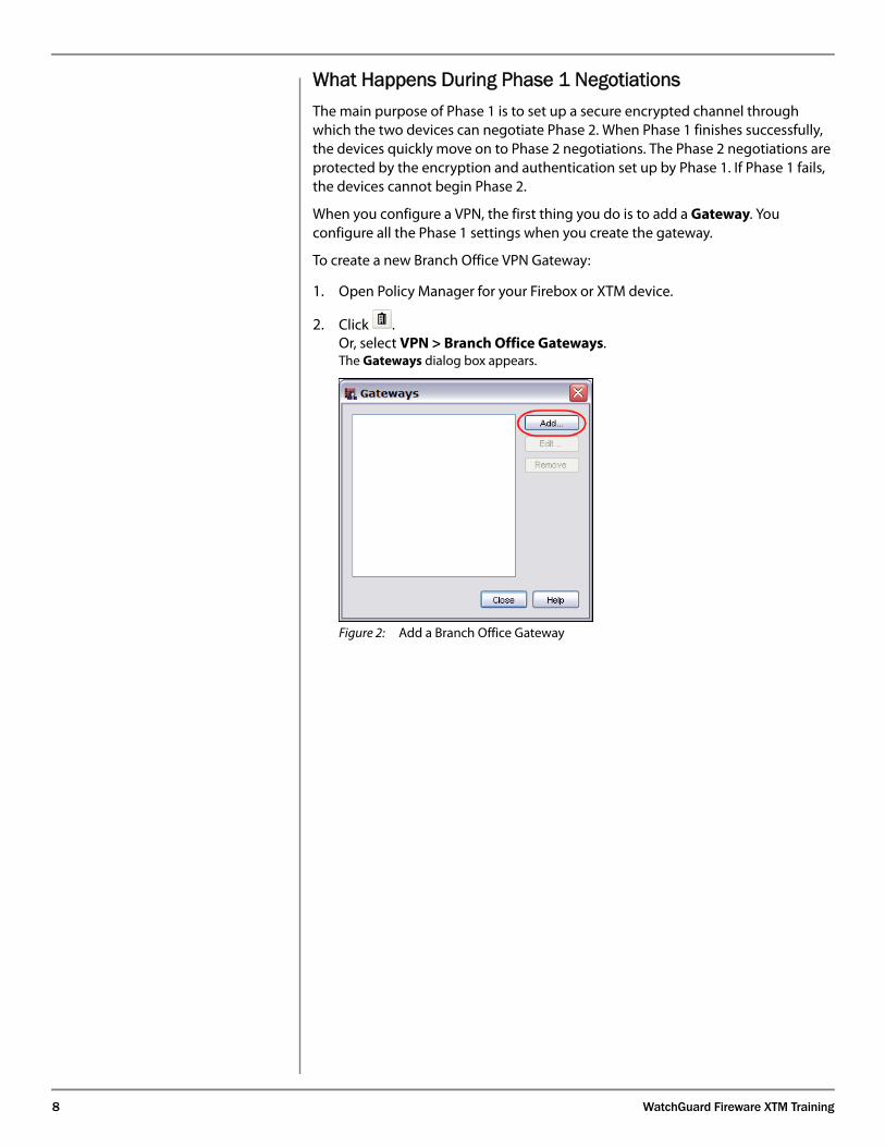
What Happens During Phase 1 NegotiationsThe main purpose of Phase 1 is to set up a secure encrypted channel through which the two devices can negotiate Phase 2. When Phase 1 finishes successfully, the devices quickly move on to Phase 2 negotiations. The Phase 2 negotiations are protected by the encryption and authentication set up by Phase 1. If Phase 1 fails, the devices cannot begin Phase 2.
When you configure a VPN, the first thing you do is to add a Gateway. You configure all the Phase 1 settings when you create the gateway.
To create a new Branch Office VPN Gateway:
1. Open Policy Manager for your Firebox or XTM device.
2. Click .Or, select VPN > Branch Office Gateways.The Gateways dialog box appears.
Figure 2: Add a Branch Office Gateway
What You Should Know
9
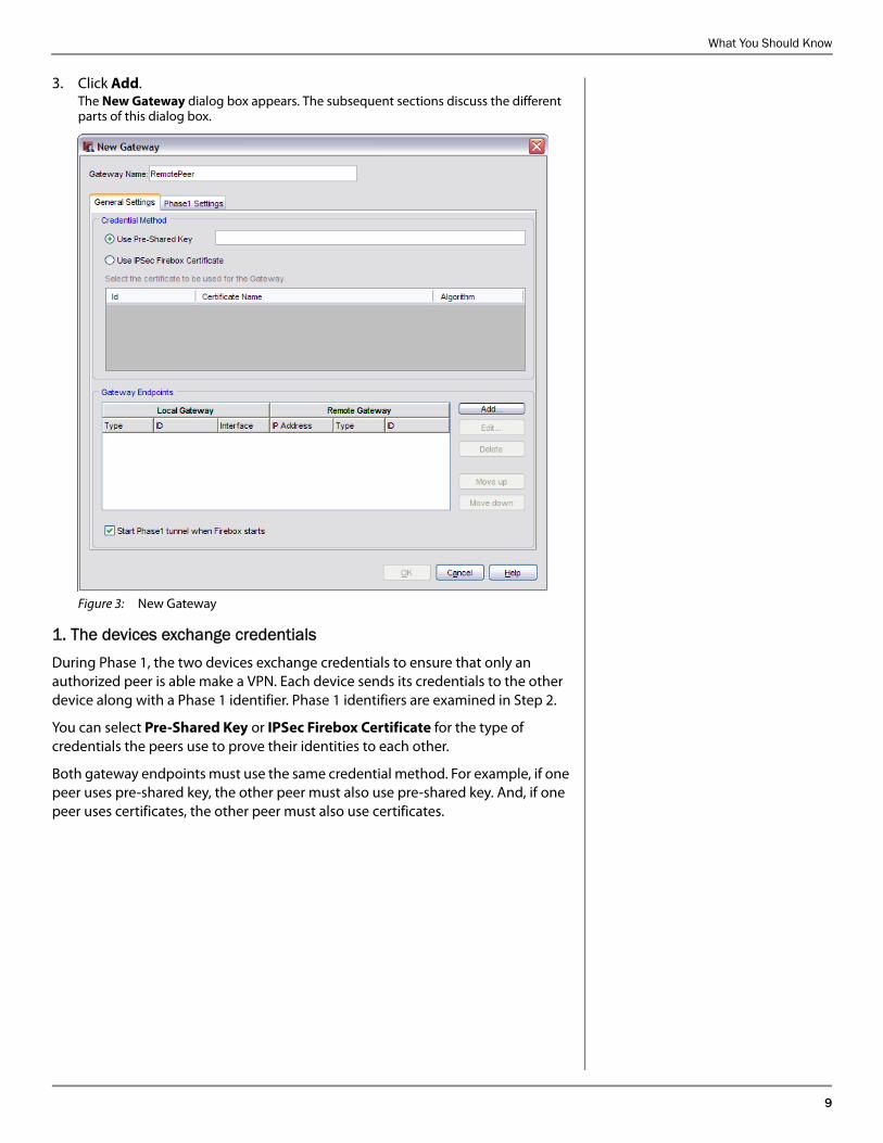
3. Click Add.The New Gateway dialog box appears. The subsequent sections discuss the different parts of this dialog box.
Figure 3: New Gateway
1. The devices exchange credentials During Phase 1, the two devices exchange credentials to ensure that only an authorized peer is able make a VPN. Each device sends its credentials to the other device along with a Phase 1 identifier. Phase 1 identifiers are examined in Step 2.
You can select Pre-Shared Key or IPSec Firebox Certificate for the type of credentials the peers use to prove their identities to each other.
Both gateway endpoints must use the same credential method. For example, if one peer uses pre-shared key, the other peer must also use pre-shared key. And, if one peer uses certificates, the other peer must also use certificates.
10 WatchGuard Fireware XTM Training
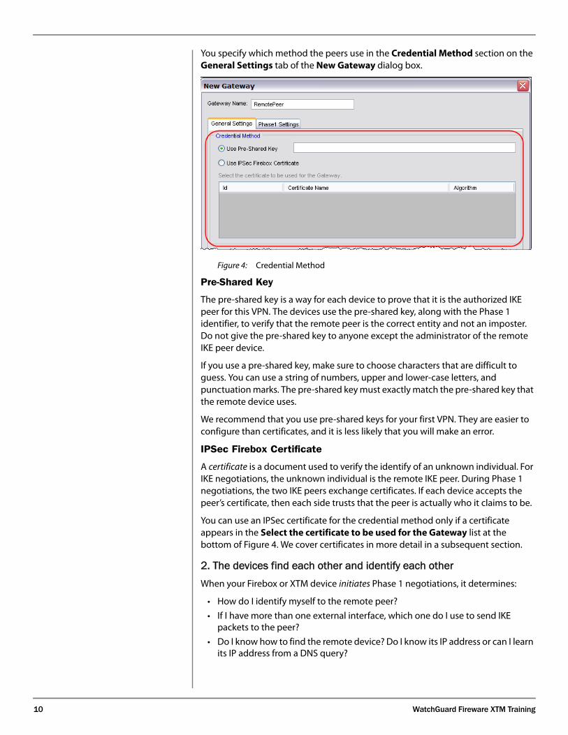
You specify which method the peers use in the Credential Method section on the General Settings tab of the New Gateway dialog box.
Figure 4: Credential Method
Pre-Shared Key
The pre-shared key is a way for each device to prove that it is the authorized IKE peer for this VPN. The devices use the pre-shared key, along with the Phase 1 identifier, to verify that the remote peer is the correct entity and not an imposter. Do not give the pre-shared key to anyone except the administrator of the remote IKE peer device.
If you use a pre-shared key, make sure to choose characters that are difficult to guess. You can use a string of numbers, upper and lower-case letters, and punctuation marks. The pre-shared key must exactly match the pre-shared key that the remote device uses.
We recommend that you use pre-shared keys for your first VPN. They are easier to configure than certificates, and it is less likely that you will make an error.
IPSec Firebox Certificate
A certificate is a document used to verify the identify of an unknown individual. For IKE negotiations, the unknown individual is the remote IKE peer. During Phase 1 negotiations, the two IKE peers exchange certificates. If each device accepts the peer’s certificate, then each side trusts that the peer is actually who it claims to be.
You can use an IPSec certificate for the credential method only if a certificate appears in the Select the certificate to be used for the Gateway list at the bottom of Figure 4. We cover certificates in more detail in a subsequent section.
2. The devices find each other and identify each other When your Firebox or XTM device initiates Phase 1 negotiations, it determines:
• How do I identify myself to the remote peer?
• If I have more than one external interface, which one do I use to send IKE packets to the peer?
• Do I know how to find the remote device? Do I know its IP address or can I learn its IP address from a DNS query?
What You Should Know
11
When your Firebox or XTM device responds to IKE negotiations from the peer, your Firebox or XTM device must decide:
• Does my configuration allow me to negotiate with this device, based on the way the device identifies itself and the source IP address of the IKE packets?
• If I specified more than one external interface for this peer to use for negotiations, did the IKE packets come to the correct one?
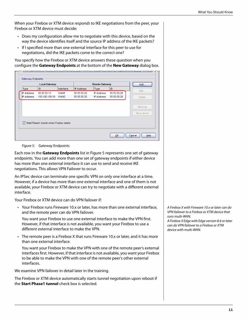
You specify how the Firebox or XTM device answers these question when you configure the Gateway Endpoints at the bottom of the New Gateway dialog box.
Figure 5: Gateway Endpoints
Each row in the Gateway Endpoints list in Figure 5 represents one set of gateway endpoints. You can add more than one set of gateway endpoints if either device has more than one external interface it can use to send and receive IKE negotiations. This allows VPN Failover to occur.
An IPSec device can terminate one specific VPN on only one interface at a time. However, if a device has more than one external interface and one of them is not available, your Firebox or XTM device can try to negotiate with a different external interface.
Your Firebox or XTM device can do VPN failover if:
A Firebox X with Fireware 10.x or later can do VPN failover to a Firebox or XTM device that runs multi-WAN. A Firebox X Edge with Edge version 8.6 or later can do VPN failover to a Firebox or XTM device with multi-WAN.
• Your Firebox runs Fireware 10.x or later, has more than one external interface, and the remote peer can do VPN failover.
You want your Firebox to use one external interface to make the VPN first. However, if that interface is not available, you want your Firebox to use a different external interface to make the VPN.
• The remote peer is a Firebox X that runs Fireware 10.x or later, and it has more than one external interface.
You want your Firebox to make the VPN with one of the remote peer’s external interfaces first. However, if that interface is not available, you want your Firebox to be able to make the VPN with one of the remote peer’s other external interfaces.
We examine VPN failover in detail later in the training.
The Firebox or XTM device automatically starts tunnel negotiation upon reboot if the Start Phase1 tunnel check box is selected.
12 WatchGuard Fireware XTM Training
To add a set of gateway endpoints:
1. Open the New Gateway dialog box.
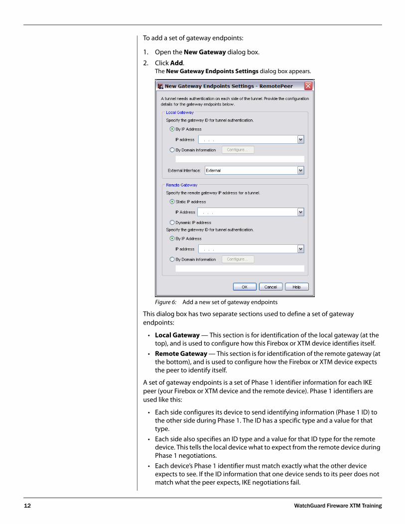
2. Click Add. The New Gateway Endpoints Settings dialog box appears.
Figure 6: Add a new set of gateway endpoints
This dialog box has two separate sections used to define a set of gateway endpoints:
• Local Gateway — This section is for identification of the local gateway (at the top), and is used to configure how this Firebox or XTM device identifies itself.
• Remote Gateway — This section is for identification of the remote gateway (at the bottom), and is used to configure how the Firebox or XTM device expects the peer to identify itself.
A set of gateway endpoints is a set of Phase 1 identifier information for each IKE peer (your Firebox or XTM device and the remote device). Phase 1 identifiers are used like this:
• Each side configures its device to send identifying information (Phase 1 ID) to the other side during Phase 1. The ID has a specific type and a value for that type.
• Each side also specifies an ID type and a value for that ID type for the remote device. This tells the local device what to expect from the remote device during Phase 1 negotiations.
• Each device’s Phase 1 identifier must match exactly what the other device expects to see. If the ID information that one device sends to its peer does not match what the peer expects, IKE negotiations fail.
What You Should Know
13
Each device can use one of four types of identifiers, or Phase 1 ID types:
After each ID type we show the common representation of the ID type as it is defined in the relevant RFCs. For example, with the IP Address ID Type, the IKE RFCs define the ID type ID_IPv4_ADDR.
• IP Address (ID_IPv4_ADDR)
The value for this ID type must be a dotted-decimal IP address, without a subnet mask. This is almost always the IP address assigned to the device interface that terminates the VPN.
In some network topologies, the value for the IP address ID type can instead be the IP address of a device configured for Network Address Translation (NAT) that is between the IPSec device and the Internet. In these cases, the NAT device has a one-to-one NAT mapping that sends all ports and protocols to the IPSec device behind it.
• Domain Name (ID_FQDN)
The value for this ID type is a string of text. This is usually a fully qualified domain name (such as firebox.domain.com or mywatchguard.com) that has a record in the DNS system for the IP address assigned to the external interface.
When the appliance has a dynamic IP address but no DNS record, you can use this ID type and the next one (User ID on Domain) in a similar way. A later side note tells you the main difference between the two types in this situation.
It is not necessary for this name to have a corresponding record in DNS. The value for this ID type can also be a simple name that serves only as a Phase 1 identifier, but does not have an address record in DNS.
If your Firebox or XTM device has a static IP address on the external interface and you publish a DNS record for this IP address, you can use the domain name for the Phase 1 identifier. The other device can learn your Firebox or XTM device IP address by doing a DNS query for the domain name. However in these cases you usually use the IP address for the Phase 1 identifier because the IP address never changes.
If your Firebox or XTM device has a dynamic IP address and you use the Dynamic DNS service, you can use the DynDNS host name for your Phase 1 identifier, for example, myfirebox.dyndns.org. The dynamic DNS service lets the remote peer find your Firebox or XTM device with a DNS query even when your Firebox or XTM device IP address changes often, so that the peer can initiate IKE negotiations.
Keep in mind that this ID type is intended to relate to a DNS record but it is not necessary. Consider this scenario:
IPSec device A has a dynamic IP address but does not use a dynamic DNS service. Thus the DNS system has no record for device A’s external interface. Device A can use Domain Name for its ID type, and the value can be a string of text that does not have a record in the DNS system. This is the only identifier information that the other IKE peer, device B, knows about device A. When device B wants to initiate IKE negotiations to make the VPN to A, device B sends a DNS query to resolve this name to an IP address. The DNS query fails and device B cannot find device A. In this scenario, device A must be the initiator. IKE negotiations can succeed in this scenario as long as all other parameters match. Aggressive Mode must be used.
If you use certificates for the credential method, the value for this ID type is the DNS Name or Domain Name field in the certificate. When you view the certificate with a Windows certificate viewer, the certificate field name is DNS Name, and it is listed as a Subject Alternative Name.
14 WatchGuard Fireware XTM Training
Some IPSec appliances can use “User ID on Domain” for the remote peer only, and cannot use it for the local identifier. — Firebox SOHO, SOHO 6, and Edge appliances cannot use User ID for the local gateway identifier. — Appliances running Fireware XTM and WFS can use User ID for the local ID.
• User ID on Domain (ID_USER_FQDN)
This is typically a user’s ID in the form of an email address, such as [email protected]. It can also be a simple string of text that does not represent a real email address, such as bobs_firebox.
If you do not use certificates for the credential method, the value of the ID is only a string of identifying text. It can be a real email address, or just a simple name.
You usually use this ID type when the remote IKE peer is a user who connects from a single computer (instead of an IPSec device such as a firewall). This is the case with the WatchGuard Mobile VPN client; the software uses User ID on Domain for its local Phase 1 identifier. (In the SafeNet Security Policy settings it is named email address but the Phase 1 ID type that the remote client sends is actually ID_USER_FQDN.)
The main difference between the “User ID on Domain” and the “Domain Name” ID types when the external IP address is dynamic is this: the peer does not try to resolve a “User ID on Domain” with a DNS query, but it usually does try to resolve a “Domain Name”. With User ID on Domain, the peer simply waits for the remote device to begin IKE negotiations. With Domain Name the peer can try to initiate negotiations by first doing a DNS query to find the other device.
If an IPSec appliance that acts as the IKE gateway supports it, this ID type can be the device’s own local Phase 1 identifier.
You can use this ID type for the local identifier if your Firebox or XTM device has a static IP address or a dynamic IP address on its external interface. If the IP address on your Firebox or XTM device is dynamic, this ID type creates a situation that is similar to the previous scenario (a domain name that does not resolve to an IP address in DNS). When a device has a dynamic IP address and it uses this ID type for its Phase 1 identifier, it must be the initiator. This is because the identifier alone is not sufficient information for its peer to find it. The value for this ID type never resolves to an IP address in DNS.
If you use certificates for the credential method, the value for this ID type is usually the email address field in the certificate. The certificate field name is RFC822 Name, and is listed as a Subject Alternative Name when you view the certificate with a Windows certificate viewer.
• X500 name (ID_DER_ASN1_DN)
Use this ID type only when you use certificates for the credential method. The value for the ID is the value of the certificate’s Subject field. The format of an X500 name is similar to the format of a distinguished name in an LDAP-style directory service. For example:CN=MyWatchGuard,OU=Main Office,O=mywatchguard.com,ST=NY,C=US
The Local Gateway Identifier
When the Firebox or XTM device uses multi-WAN and VPN failover, be sure to stress the importance of specifying the correct external interface in Figure 7. This is by far the most common mistake users make when configuring multiple gateway endpoints: they forget to select a different external interface when adding the second pair of gateway endpoints.
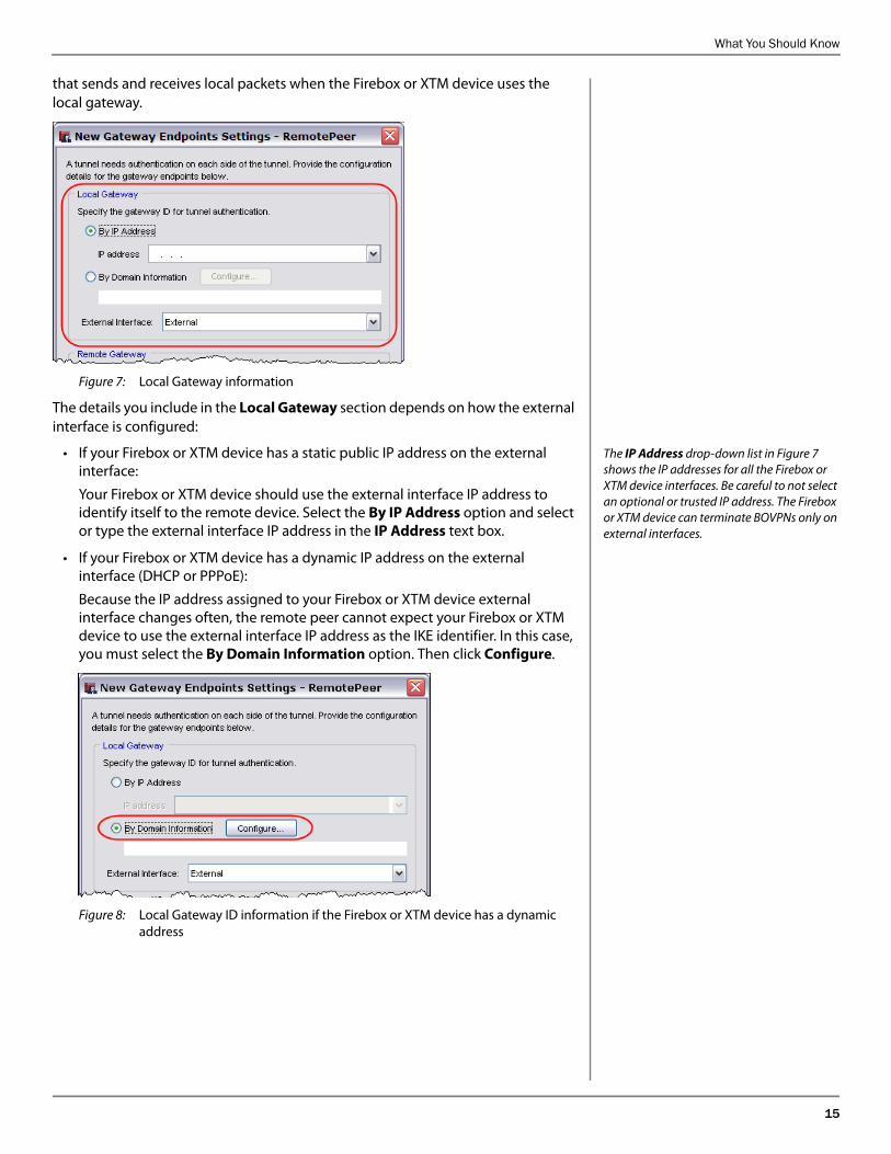
In the Local Gateway section, you configure the gateway identification information for the Firebox or XTM device. You also configure the external interface
What You Should Know
15
that sends and receives local packets when the Firebox or XTM device uses the local gateway.
Figure 7: Local Gateway information
The details you include in the Local Gateway section depends on how the external interface is configured:
The IP Address drop-down list in Figure 7 shows the IP addresses for all the Firebox or XTM device interfaces. Be careful to not select an optional or trusted IP address. The Firebox or XTM device can terminate BOVPNs only on external interfaces.
• If your Firebox or XTM device has a static public IP address on the external interface:
Your Firebox or XTM device should use the external interface IP address to identify itself to the remote device. Select the By IP Address option and select or type the external interface IP address in the IP Address text box.
• If your Firebox or XTM device has a dynamic IP address on the external interface (DHCP or PPPoE):
Because the IP address assigned to your Firebox or XTM device external interface changes often, the remote peer cannot expect your Firebox or XTM device to use the external interface IP address as the IKE identifier. In this case, you must select the By Domain Information option. Then click Configure.
Figure 8: Local Gateway ID information if the Firebox or XTM device has a dynamic address
16 WatchGuard Fireware XTM Training
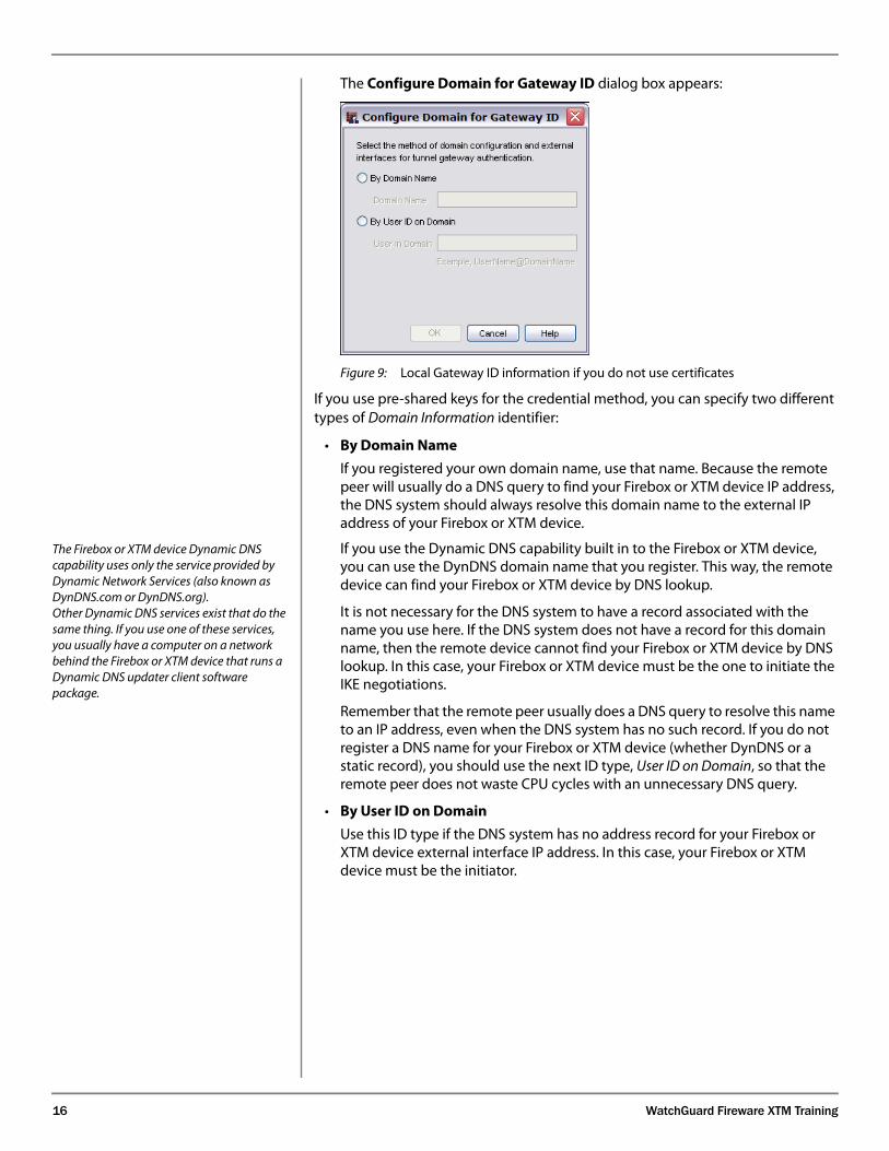
The Configure Domain for Gateway ID dialog box appears:
Figure 9: Local Gateway ID information if you do not use certificates
If you use pre-shared keys for the credential method, you can specify two different types of Domain Information identifier:
• By Domain Name
If you registered your own domain name, use that name. Because the remote peer will usually do a DNS query to find your Firebox or XTM device IP address, the DNS system should always resolve this domain name to the external IP address of your Firebox or XTM device.
The Firebox or XTM device Dynamic DNS capability uses only the service provided by Dynamic Network Services (also known as DynDNS.com or DynDNS.org).Other Dynamic DNS services exist that do the same thing. If you use one of these services, you usually have a computer on a network behind the Firebox or XTM device that runs a Dynamic DNS updater client software package.
If you use the Dynamic DNS capability built in to the Firebox or XTM device, you can use the DynDNS domain name that you register. This way, the remote device can find your Firebox or XTM device by DNS lookup.
It is not necessary for the DNS system to have a record associated with the name you use here. If the DNS system does not have a record for this domain name, then the remote device cannot find your Firebox or XTM device by DNS lookup. In this case, your Firebox or XTM device must be the one to initiate the IKE negotiations.
Remember that the remote peer usually does a DNS query to resolve this name to an IP address, even when the DNS system has no such record. If you do not register a DNS name for your Firebox or XTM device (whether DynDNS or a static record), you should use the next ID type, User ID on Domain, so that the remote peer does not waste CPU cycles with an unnecessary DNS query.
• By User ID on Domain
Use this ID type if the DNS system has no address record for your Firebox or XTM device external interface IP address. In this case, your Firebox or XTM device must be the initiator.
What You Should Know
17
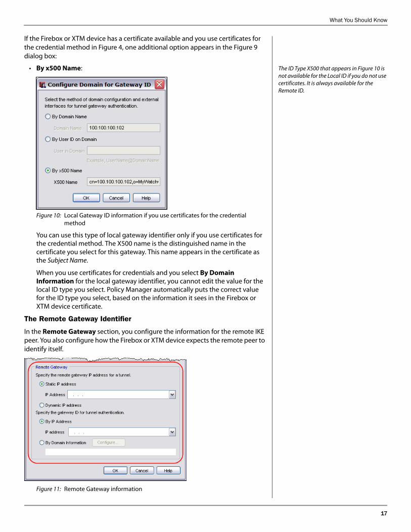
If the Firebox or XTM device has a certificate available and you use certificates for the credential method in Figure 4, one additional option appears in the Figure 9 dialog box:
The ID Type X500 that appears in Figure 10 is not available for the Local ID if you do not use certificates. It is always available for the Remote ID.
• By x500 Name:
Figure 10: Local Gateway ID information if you use certificates for the credential method
You can use this type of local gateway identifier only if you use certificates for the credential method. The X500 name is the distinguished name in the certificate you select for this gateway. This name appears in the certificate as the Subject Name.
When you use certificates for credentials and you select By Domain Information for the local gateway identifier, you cannot edit the value for the local ID type you select. Policy Manager automatically puts the correct value for the ID type you select, based on the information it sees in the Firebox or XTM device certificate.
The Remote Gateway Identifier
In the Remote Gateway section, you configure the information for the remote IKE peer. You also configure how the Firebox or XTM device expects the remote peer to identify itself.
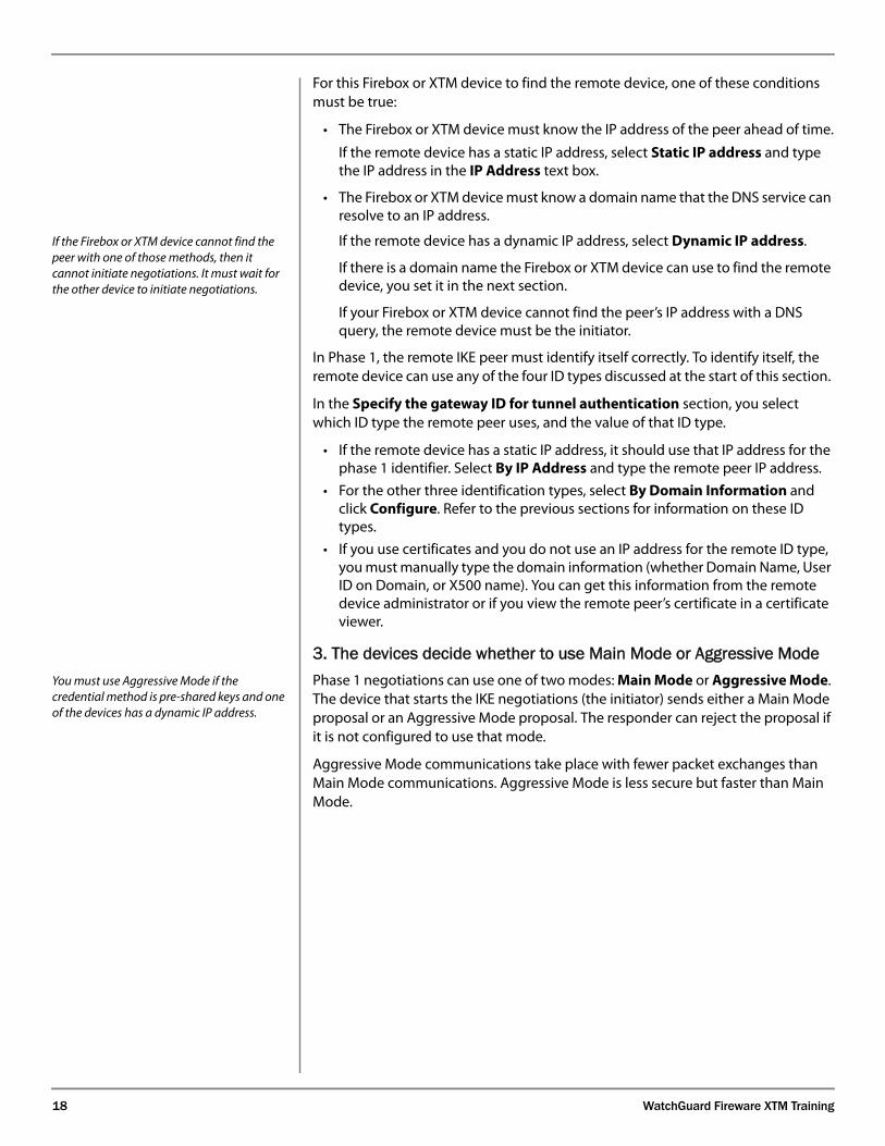
Figure 11: Remote Gateway information
18 WatchGuard Fireware XTM Training
For this Firebox or XTM device to find the remote device, one of these conditions must be true:
• The Firebox or XTM device must know the IP address of the peer ahead of time.
If the remote device has a static IP address, select Static IP address and type the IP address in the IP Address text box.
• The Firebox or XTM device must know a domain name that the DNS service can resolve to an IP address.
If the Firebox or XTM device cannot find the peer with one of those methods, then it cannot initiate negotiations. It must wait for the other device to initiate negotiations.
If the remote device has a dynamic IP address, select Dynamic IP address.
If there is a domain name the Firebox or XTM device can use to find the remote device, you set it in the next section.
If your Firebox or XTM device cannot find the peer’s IP address with a DNS query, the remote device must be the initiator.
In Phase 1, the remote IKE peer must identify itself correctly. To identify itself, the remote device can use any of the four ID types discussed at the start of this section.
In the Specify the gateway ID for tunnel authentication section, you select which ID type the remote peer uses, and the value of that ID type.
• If the remote device has a static IP address, it should use that IP address for the phase 1 identifier. Select By IP Address and type the remote peer IP address.
• For the other three identification types, select By Domain Information and click Configure. Refer to the previous sections for information on these ID types.
• If you use certificates and you do not use an IP address for the remote ID type, you must manually type the domain information (whether Domain Name, User ID on Domain, or X500 name). You can get this information from the remote device administrator or if you view the remote peer’s certificate in a certificate viewer.
3. The devices decide whether to use Main Mode or Aggressive ModeYou must use Aggressive Mode if the credential method is pre-shared keys and one of the devices has a dynamic IP address.
Phase 1 negotiations can use one of two modes: Main Mode or Aggressive Mode. The device that starts the IKE negotiations (the initiator) sends either a Main Mode proposal or an Aggressive Mode proposal. The responder can reject the proposal if it is not configured to use that mode.
Aggressive Mode communications take place with fewer packet exchanges than Main Mode communications. Aggressive Mode is less secure but faster than Main Mode.
What You Should Know
19
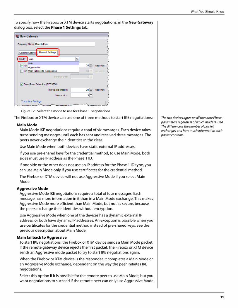
To specify how the Firebox or XTM device starts negotiations, in the New Gateway dialog box, select the Phase 1 Settings tab.
Figure 12: Select the mode to use for Phase 1 negotiations
The two devices agree on all the same Phase 1 parameters regardless of which mode is used. The difference is the number of packet exchanges and how much information each packet contains.
The Firebox or XTM device can use one of three methods to start IKE negotiations:
Main ModeMain Mode IKE negotiations require a total of six messages. Each device takes turns sending messages until each has sent and received three messages. The peers never exchange their identities in the clear.
Use Main Mode when both devices have static external IP addresses.
If you use pre-shared keys for the credential method, to use Main Mode, both sides must use IP address as the Phase 1 ID.
If one side or the other does not use an IP address for the Phase 1 ID type, you can use Main Mode only if you use certificates for the credential method.
The Firebox or XTM device will not use Aggressive Mode if you select Main Mode.
Aggressive ModeAggressive Mode IKE negotiations require a total of four messages. Each message has more information in it than in a Main Mode exchange. This makes Aggressive Mode more efficient than Main Mode, but not as secure, because the peers exchange their identities without encryption.
Use Aggressive Mode when one of the devices has a dynamic external IP address, or both have dynamic IP addresses. An exception is possible when you use certificates for the credential method instead of pre-shared keys. See the previous description about Main Mode.
Main failback to AggressiveTo start IKE negotiations, the Firebox or XTM device sends a Main Mode packet. If the remote gateway device rejects the first packet, the Firebox or XTM device sends an Aggressive mode packet to try to start IKE negotiations again.
When the Firebox or XTM device is the responder, it completes a Main Mode or an Aggressive Mode exchange, dependant on the way the peer initiates IKE negotiations.
Select this option if it is possible for the remote peer to use Main Mode, but you want negotiations to succeed if the remote peer can only use Aggressive Mode.
20 WatchGuard Fireware XTM Training
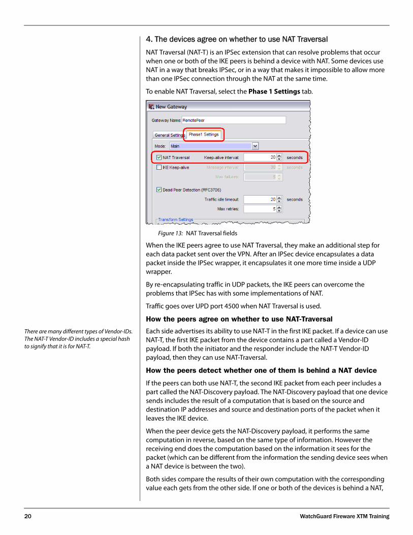
4. The devices agree on whether to use NAT TraversalNAT Traversal (NAT-T) is an IPSec extension that can resolve problems that occur when one or both of the IKE peers is behind a device with NAT. Some devices use NAT in a way that breaks IPSec, or in a way that makes it impossible to allow more than one IPSec connection through the NAT at the same time.
To enable NAT Traversal, select the Phase 1 Settings tab.
Figure 13: NAT Traversal fields
When the IKE peers agree to use NAT Traversal, they make an additional step for each data packet sent over the VPN. After an IPSec device encapsulates a data packet inside the IPSec wrapper, it encapsulates it one more time inside a UDP wrapper.
By re-encapsulating traffic in UDP packets, the IKE peers can overcome the problems that IPSec has with some implementations of NAT.
Traffic goes over UPD port 4500 when NAT Traversal is used.
How the peers agree on whether to use NAT-Traversal
There are many different types of Vendor-IDs. The NAT-T Vendor-ID includes a special hash to signify that it is for NAT-T.
Each side advertises its ability to use NAT-T in the first IKE packet. If a device can use NAT-T, the first IKE packet from the device contains a part called a Vendor-ID payload. If both the initiator and the responder include the NAT-T Vendor-ID payload, then they can use NAT-Traversal.
How the peers detect whether one of them is behind a NAT device
If the peers can both use NAT-T, the second IKE packet from each peer includes a part called the NAT-Discovery payload. The NAT-Discovery payload that one device sends includes the result of a computation that is based on the source and destination IP addresses and source and destination ports of the packet when it leaves the IKE device.
When the peer device gets the NAT-Discovery payload, it performs the same computation in reverse, based on the same type of information. However the receiving end does the computation based on the information it sees for the packet (which can be different from the information the sending device sees when a NAT device is between the two).
Both sides compare the results of their own computation with the corresponding value each gets from the other side. If one or both of the devices is behind a NAT,
What You Should Know
21
then the two results of the same computation do not match because NAT changes the source IP addresses, the source ports, or both. The mismatch means that there is a NAT device in front of one of the IKE peers.
If the values do match, then no NAT is detected and the devices do not use NAT-T. Even though both devices are capable of using NAT-T, it is not necessary if neither device is behind a NAT.
How data traverses the NAT
If both devices can do NAT-Traversal, and if a NAT is detected, then the devices immediately change the port they use to communicate. The remaining IKE negotiations switch to UDP port 4500. Data transfers over the VPN also use UDP port 4500, instead of ESP as the transport method.
After the VPN finishes negotiation of Phase 1 and Phase 2, actual data can be sent over the VPN. When NAT-T is used, data sent over the VPN is encapsulated in IPSec before the device sends it, just as the device normally does without NAT-T. However, with NAT-T each packet is re-encapsulated one more time inside a UDP port 4500 packet before the device sends it.
When the peer gets a NAT-T packet that contains data, it unwraps the IPSec packet from the UDP encapsulation. Then it can process the resulting packet as it normally does for IPSec traffic.
The NAT Traversal Keep-Alive
The NAT-T keep-alive keeps the NAT open on the NAT device.
A NAT device does outbound Network Address Translation by changing the source port and source IP address of a packet before it sends it. The device keeps a mapping between the original source port / original source IP address and the new source port / new source IP address. It uses the mapping so that when a packet returns in response (when the destination of the response packet is the translated source port and translated source IP address), it can send the response back to the correct computer (the response to the original IP address that started the data flow is sent with the flow’s original source port).
The NAT device maintains this mapping for only a short time when there is no traffic that matches the mapping. If the device does not see traffic that uses the NAT mapping for a certain amount of time, it closes the NAT. NAT timeouts for UDP traffic are typically much lower than NAT timeouts for TCP connections.
If UDP-encapsulated traffic is sent from behind the NAT device, NAT is opened on the NAT device.
To keep the IPSec tunnel active when NAT-T is used, the IPSec devices keep the NAT mapping alive. The IPSec device behind a NAT sends a NAT-T keep-alive packet to keep the NAT mapping active. The peer that receives the NAT keep-alive packet replies with a keep-alive ACK to keep the NAT active on the remote NAT device.
The Keep-Alive Interval affects your Firebox or XTM device only if your Firebox or XTM device is the IKE peer behind the NAT. It specifies how often your Firebox or XTM device sends a NAT keep-alive packet to keep the NAT mapping active on the NAT device in front of the Firebox or XTM device.
When the remote IKE peer is behind a NAT, it has its own settings for the keep-alive interval. Your Firebox or XTM device responds to the NAT keep-alive messages it gets from the other side, but your Firebox or XTM device does not influence the interval that the peer uses between the keep-alives it sends.
22 WatchGuard Fireware XTM Training
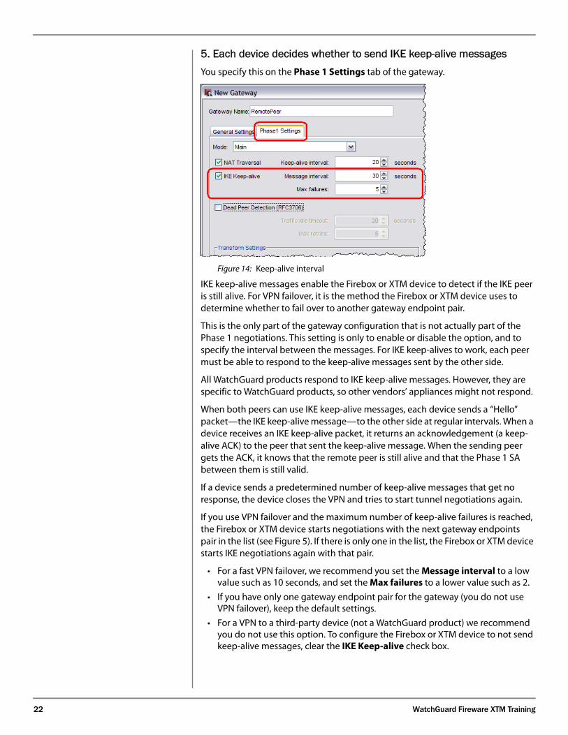
5. Each device decides whether to send IKE keep-alive messages You specify this on the Phase 1 Settings tab of the gateway.
Figure 14: Keep-alive interval
The IKE Keep-Alive packets consist of encrypted INFORMATION exchange packets that have a NOTIFY payload. The NOTIFY types are:KEEPALIVE_REQUEST 32768KEEPALIVE_ACK 32769
IKE keep-alive messages enable the Firebox or XTM device to detect if the IKE peer is still alive. For VPN failover, it is the method the Firebox or XTM device uses to determine whether to fail over to another gateway endpoint pair.
This is the only part of the gateway configuration that is not actually part of the Phase 1 negotiations. This setting is only to enable or disable the option, and to specify the interval between the messages. For IKE keep-alives to work, each peer must be able to respond to the keep-alive messages sent by the other side.
All WatchGuard products respond to IKE keep-alive messages. However, they are specific to WatchGuard products, so other vendors’ appliances might not respond.
When both peers can use IKE keep-alive messages, each device sends a “Hello” packet—the IKE keep-alive message—to the other side at regular intervals. When a device receives an IKE keep-alive packet, it returns an acknowledgement (a keep-alive ACK) to the peer that sent the keep-alive message. When the sending peer gets the ACK, it knows that the remote peer is still alive and that the Phase 1 SA between them is still valid.
If a device sends a predetermined number of keep-alive messages that get no response, the device closes the VPN and tries to start tunnel negotiations again.
If you use VPN failover and the maximum number of keep-alive failures is reached, the Firebox or XTM device starts negotiations with the next gateway endpoints pair in the list (see Figure 5). If there is only one in the list, the Firebox or XTM device starts IKE negotiations again with that pair.
• For a fast VPN failover, we recommend you set the Message interval to a low value such as 10 seconds, and set the Max failures to a lower value such as 2.
• If you have only one gateway endpoint pair for the gateway (you do not use VPN failover), keep the default settings.
• For a VPN to a third-party device (not a WatchGuard product) we recommend you do not use this option. To configure the Firebox or XTM device to not send keep-alive messages, clear the IKE Keep-alive check box.
What You Should Know
23
• For a VPN to any Firebox or XTM device that can use Dead Peer Detection, we recommend you do not use this option. To configure the Firebox to not send keep-alive messages, clear the IKE Keep-alive check box.
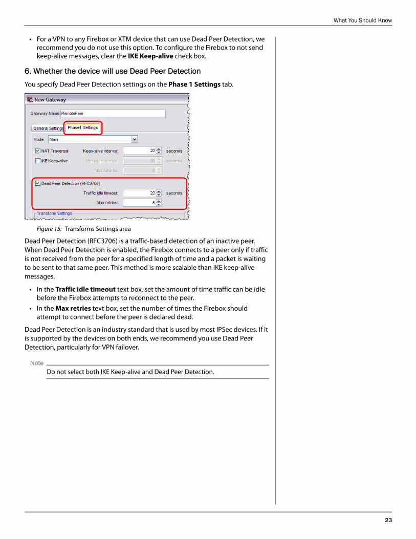
6. Whether the device will use Dead Peer DetectionYou specify Dead Peer Detection settings on the Phase 1 Settings tab.
Figure 15: Transforms Settings area
Dead Peer Detection (RFC3706) is a traffic-based detection of an inactive peer. When Dead Peer Detection is enabled, the Firebox connects to a peer only if traffic is not received from the peer for a specified length of time and a packet is waiting to be sent to that same peer. This method is more scalable than IKE keep-alive messages.
• In the Traffic idle timeout text box, set the amount of time traffic can be idle before the Firebox attempts to reconnect to the peer.
• In the Max retries text box, set the number of times the Firebox should attempt to connect before the peer is declared dead.
Dead Peer Detection is an industry standard that is used by most IPSec devices. If it is supported by the devices on both ends, we recommend you use Dead Peer Detection, particularly for VPN failover.
Note
Do not select both IKE Keep-alive and Dead Peer Detection.
24 WatchGuard Fireware XTM Training
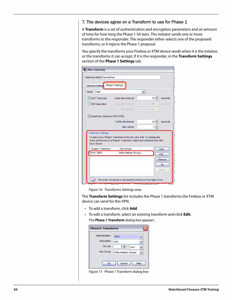
7. The devices agree on a Transform to use for Phase 1 A Transform is a set of authentication and encryption parameters and an amount of time for how long the Phase 1 SA lasts. The initiator sends one or more transforms to the responder. The responder either selects one of the proposed transforms, or it rejects the Phase 1 proposal.
You specify the transforms your Firebox or XTM device sends when it is the initiator, or the transforms it can accept, if it is the responder, in the Transform Settings section of the Phase 1 Settings tab.
Figure 16: Transforms Settings area
The Transform Settings list includes the Phase 1 transforms the Firebox or XTM device can send for this VPN.
• To add a transform, click Add.
• To edit a transform, select an existing transform and click Edit. The Phase 1 Transform dialog box appears.
Figure 17: Phase 1 Transform dialog box
What You Should Know
25
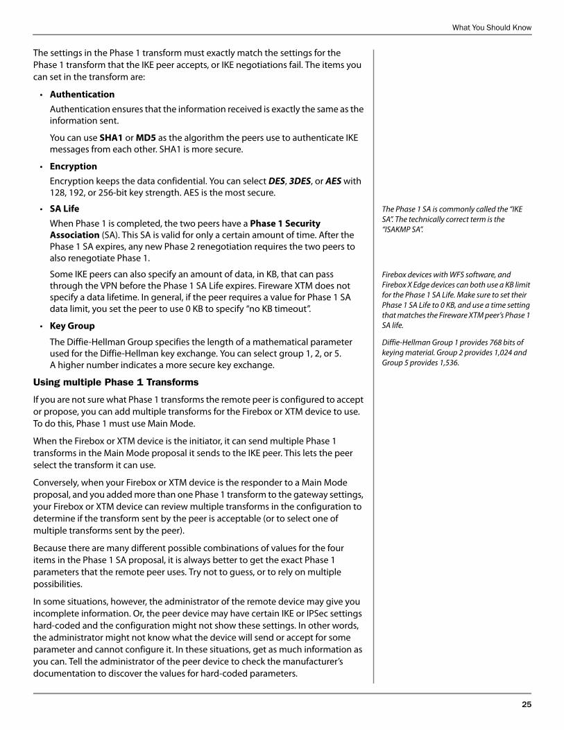
The settings in the Phase 1 transform must exactly match the settings for the Phase 1 transform that the IKE peer accepts, or IKE negotiations fail. The items you can set in the transform are:
• Authentication
Authentication ensures that the information received is exactly the same as the information sent.
You can use SHA1 or MD5 as the algorithm the peers use to authenticate IKE messages from each other. SHA1 is more secure.
• Encryption
Encryption keeps the data confidential. You can select DES, 3DES, or AES with 128, 192, or 256-bit key strength. AES is the most secure.
The Phase 1 SA is commonly called the “IKE SA”. The technically correct term is the “ISAKMP SA”.
• SA Life
When Phase 1 is completed, the two peers have a Phase 1 Security Association (SA). This SA is valid for only a certain amount of time. After the Phase 1 SA expires, any new Phase 2 renegotiation requires the two peers to also renegotiate Phase 1.
Firebox devices with WFS software, and Firebox X Edge devices can both use a KB limit for the Phase 1 SA Life. Make sure to set their Phase 1 SA Life to 0 KB, and use a time setting that matches the Fireware XTM peer’s Phase 1 SA life.
Some IKE peers can also specify an amount of data, in KB, that can pass through the VPN before the Phase 1 SA Life expires. Fireware XTM does not specify a data lifetime. In general, if the peer requires a value for Phase 1 SA data limit, you set the peer to use 0 KB to specify “no KB timeout”.
• Key Group
Diffie-Hellman Group 1 provides 768 bits of keying material. Group 2 provides 1,024 and Group 5 provides 1,536.
The Diffie-Hellman Group specifies the length of a mathematical parameter used for the Diffie-Hellman key exchange. You can select group 1, 2, or 5. A higher number indicates a more secure key exchange.
Using multiple Phase 1 Transforms
If you are not sure what Phase 1 transforms the remote peer is configured to accept or propose, you can add multiple transforms for the Firebox or XTM device to use. To do this, Phase 1 must use Main Mode.
When the Firebox or XTM device is the initiator, it can send multiple Phase 1 transforms in the Main Mode proposal it sends to the IKE peer. This lets the peer select the transform it can use.
Conversely, when your Firebox or XTM device is the responder to a Main Mode proposal, and you added more than one Phase 1 transform to the gateway settings, your Firebox or XTM device can review multiple transforms in the configuration to determine if the transform sent by the peer is acceptable (or to select one of multiple transforms sent by the peer).
Because there are many different possible combinations of values for the four items in the Phase 1 SA proposal, it is always better to get the exact Phase 1 parameters that the remote peer uses. Try not to guess, or to rely on multiple possibilities.
In some situations, however, the administrator of the remote device may give you incomplete information. Or, the peer device may have certain IKE or IPSec settings hard-coded and the configuration might not show these settings. In other words, the administrator might not know what the device will send or accept for some parameter and cannot configure it. In these situations, get as much information as you can. Tell the administrator of the peer device to check the manufacturer’s documentation to discover the values for hard-coded parameters.
26 WatchGuard Fireware XTM Training
NoteYou can add more than one Phase 1 transform only if you use Main Mode for Phase 1. If you use Aggressive Mode, you can only have one Phase 1 transform
in the gateway configuration.
When Phase 1 is finishedWhen Phase 1 finishes, the two devices can negotiate Phase 2 over a secure encrypted channel. Their Phase 2 negotiations are protected by the Phase 1 SA (Security Association).
Through the Phase 1 negotiations, the two IKE peers generate keying material to use for Phase 2 negotiations. We look at this aspect of Phase 1 when we discuss Perfect Forward Secrecy.
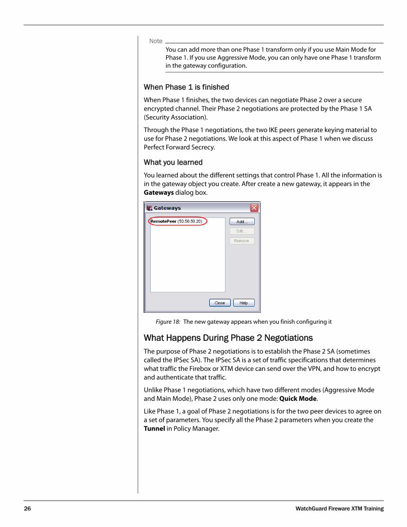
What you learnedYou learned about the different settings that control Phase 1. All the information is in the gateway object you create. After create a new gateway, it appears in the Gateways dialog box.
Figure 18: The new gateway appears when you finish configuring it
What Happens During Phase 2 NegotiationsSome of your students may be familiar with the very rigid order of VPN negotiations: Certain information must be in the first message and cannot be included in any other message. Certain information must be in, and can only be in, the second packet exchange, and so on.
In the sections that follow, we do not present the information in the same order as the ISAKMP message exchanges. Rather, the steps follow the order in which the Firebox or XTM device administrator completes the different dialog boxes.
This way you can easily go from one dialog box to the next and explain the purpose of each one.
The purpose of Phase 2 negotiations is to establish the Phase 2 SA (sometimes called the IPSec SA). The IPSec SA is a set of traffic specifications that determines what traffic the Firebox or XTM device can send over the VPN, and how to encrypt and authenticate that traffic.
Unlike Phase 1 negotiations, which have two different modes (Aggressive Mode and Main Mode), Phase 2 uses only one mode: Quick Mode.
Like Phase 1, a goal of Phase 2 negotiations is for the two peer devices to agree on a set of parameters. You specify all the Phase 2 parameters when you create the Tunnel in Policy Manager.
What You Should Know
27
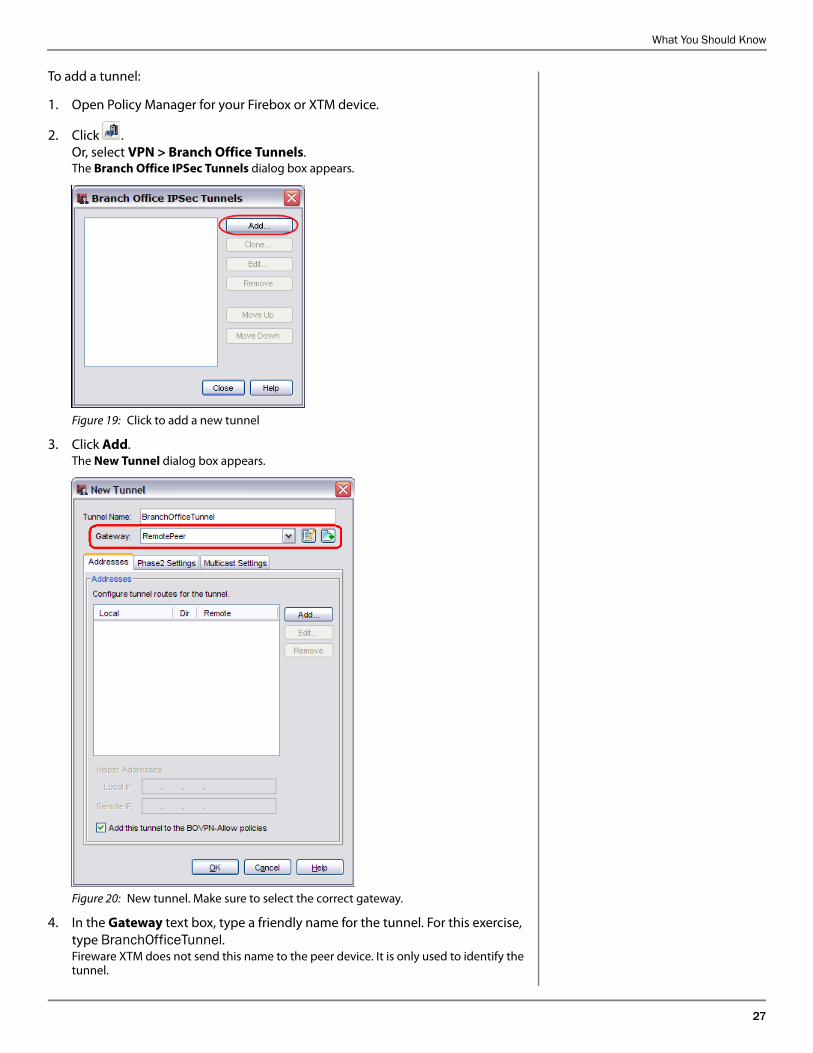
To add a tunnel:
1. Open Policy Manager for your Firebox or XTM device.
2. Click .Or, select VPN > Branch Office Tunnels.The Branch Office IPSec Tunnels dialog box appears.
Figure 19: Click to add a new tunnel
3. Click Add.The New Tunnel dialog box appears.
Figure 20: New tunnel. Make sure to select the correct gateway.
4. In the Gateway text box, type a friendly name for the tunnel. For this exercise, type BranchOfficeTunnel. Fireware XTM does not send this name to the peer device. It is only used to identify the tunnel.
28 WatchGuard Fireware XTM Training
The subsequent sections describe the purpose of each element in the tunnel configuration.
1. Peers use the Phase 1 SA to secure the Phase 2 negotiationsThe Phase 1 SA that the two peers create applies only to the two peers that negotiated the SA. If you have multiple VPNs to different remote devices, your Firebox or XTM device makes a unique Phase 1 SA to each device.
Because the Phase 2 negotiations are protected by the Phase 1 SA, you must select the correct gateway to use for the tunnel.
To select the gateway for the remote peer device to which the Firebox or XTM device sends VPN traffic for this tunnel, in the New Tunnel dialog box, click the Gateway drop-down list, and select a gateway.
2. Peers exchange Phase 2 IDsThe administrators of both IPSec devices must agree on what traffic can pass through the VPN. The two devices exchange Phase 2 IDs to specify the IP addresses behind each device that is allowed to send traffic through the VPN.
Phase 2 IDs are always sent as a pair in a Phase 2 proposal: one Phase 2 ID shows which IP addresses behind the local device can send traffic through the VPN, and the other Phase 2 ID shows which IP addresses behind the remote device can send traffic through the VPN.
If more than one pair of local/remote IP addresses can send traffic over the VPN, then a unique SA is created for each pair. The devices do a Quick Mode negotiation for each local/remote pair.
Because the Phase 2 IDs are part of the Phase 2 Security Association, they are sent as part of the Phase 2 negotiations. Fireware XTM supports three types of Phase 2 IDs:
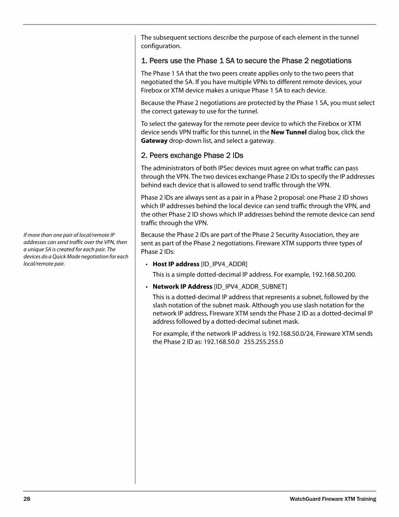
• Host IP address [ID_IPV4_ADDR]
This is a simple dotted-decimal IP address. For example, 192.168.50.200.
• Network IP Address [ID_IPV4_ADDR_SUBNET]
This is a dotted-decimal IP address that represents a subnet, followed by the slash notation of the subnet mask. Although you use slash notation for the network IP address, Fireware XTM sends the Phase 2 ID as a dotted-decimal IP address followed by a dotted-decimal subnet mask.
For example, if the network IP address is 192.168.50.0/24, Fireware XTM sends the Phase 2 ID as: 192.168.50.0 255.255.255.0
What You Should Know
29
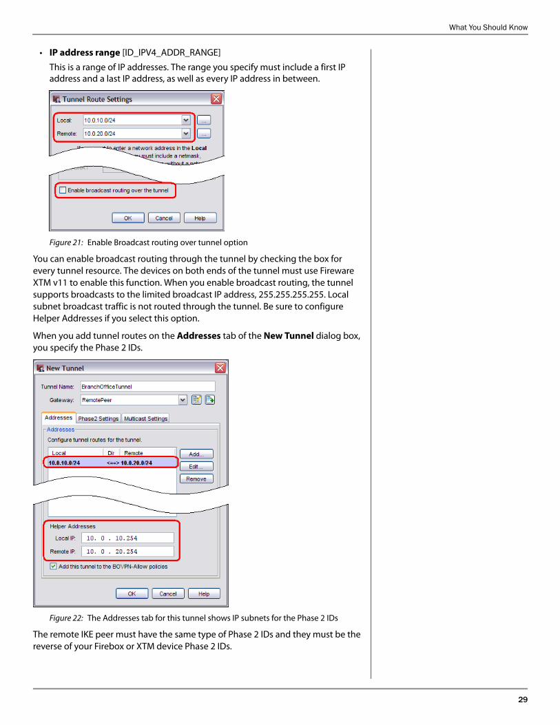
• IP address range [ID_IPV4_ADDR_RANGE]
This is a range of IP addresses. The range you specify must include a first IP address and a last IP address, as well as every IP address in between.
Figure 21: Enable Broadcast routing over tunnel option
You can enable broadcast routing through the tunnel by checking the box for every tunnel resource. The devices on both ends of the tunnel must use Fireware XTM v11 to enable this function. When you enable broadcast routing, the tunnel supports broadcasts to the limited broadcast IP address, 255.255.255.255. Local subnet broadcast traffic is not routed through the tunnel. Be sure to configure Helper Addresses if you select this option.
When you add tunnel routes on the Addresses tab of the New Tunnel dialog box, you specify the Phase 2 IDs.
Figure 22: The Addresses tab for this tunnel shows IP subnets for the Phase 2 IDs
The remote IKE peer must have the same type of Phase 2 IDs and they must be the reverse of your Firebox or XTM device Phase 2 IDs.
30 WatchGuard Fireware XTM Training
If broadcast routing through the tunnel is enabled for the added tunnel routes, the tunnel resources appear in bold. When broadcast routing is enabled, you must configure Helper Addresses. These are unused IP addresses on the network at each end of the tunnel. The Firebox or XTM device uses these addresses as the endpoints of the GRE tunnel inside the IPSec BOVPN tunnel. The Firebox or XTM device sends the broadcast traffic through the GRE tunnel.
The remote IKE peer must use the same Helper Addresses, and they must be the reverse of your Firebox or XTM device Helper Addresses.
When broadcast routing is not enabled the tunnel resources are not bold and the Helper Addresses are not required.
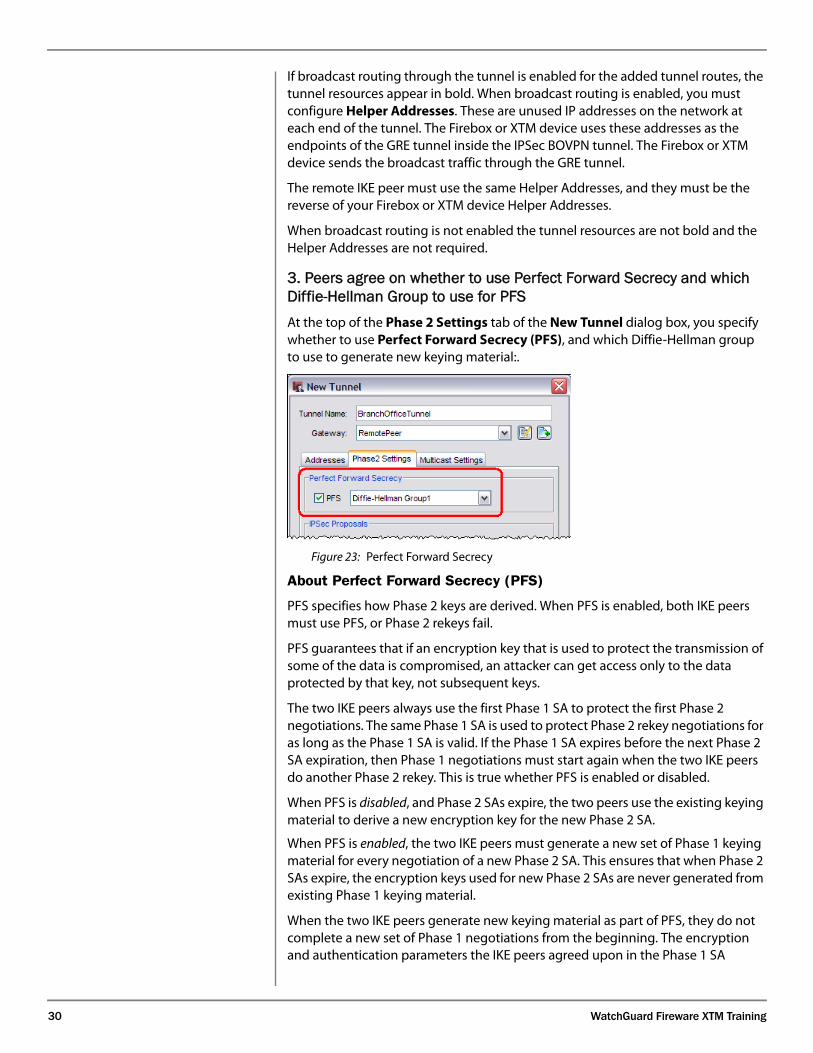
3. Peers agree on whether to use Perfect Forward Secrecy and which Diffie-Hellman Group to use for PFSAt the top of the Phase 2 Settings tab of the New Tunnel dialog box, you specify whether to use Perfect Forward Secrecy (PFS), and which Diffie-Hellman group to use to generate new keying material:.
Figure 23: Perfect Forward Secrecy
About Perfect Forward Secrecy (PFS)
PFS specifies how Phase 2 keys are derived. When PFS is enabled, both IKE peers must use PFS, or Phase 2 rekeys fail.
PFS guarantees that if an encryption key that is used to protect the transmission of some of the data is compromised, an attacker can get access only to the data protected by that key, not subsequent keys.
The two IKE peers always use the first Phase 1 SA to protect the first Phase 2 negotiations. The same Phase 1 SA is used to protect Phase 2 rekey negotiations for as long as the Phase 1 SA is valid. If the Phase 1 SA expires before the next Phase 2 SA expiration, then Phase 1 negotiations must start again when the two IKE peers do another Phase 2 rekey. This is true whether PFS is enabled or disabled.
When PFS is disabled, and Phase 2 SAs expire, the two peers use the existing keying material to derive a new encryption key for the new Phase 2 SA.
When PFS is enabled, the two peers must complete a new Diffie-Hellman key exchange for every new Quick Mode exchange. This is the “keying material” referred to in the text.
When PFS is enabled, the two IKE peers must generate a new set of Phase 1 keying material for every negotiation of a new Phase 2 SA. This ensures that when Phase 2 SAs expire, the encryption keys used for new Phase 2 SAs are never generated from existing Phase 1 keying material.
When the two IKE peers generate new keying material as part of PFS, they do not complete a new set of Phase 1 negotiations from the beginning. The encryption and authentication parameters the IKE peers agreed upon in the Phase 1 SA
What You Should Know
31
negotiations are still valid, and the authentication of the peer is still valid. These things are still valid as long as the Phase 1 lifetime does not expire.
Even though PFS does not require a new set of Phase 1 negotiations for each Phase 2 rekey, generating new session keys for every Phase 2 renegotiation is computationally expensive. Thus PFS can cause a short delay in Phase 2 rekeying.
4. Peers agree on a Phase 2 proposalAs we saw previously, the IP addresses that can send traffic over the tunnel are part of the Phase 2 SA. The remainder of the Phase 2 SA is a group of encryption and authentication parameters. Fireware XTM sends these parameters in a Phase 2 proposal. The proposal includes the algorithm to use for authenticating data, the algorithm to use for encrypting data, and the timeline to make new Phase 2 encryption keys.
32 WatchGuard Fireware XTM Training
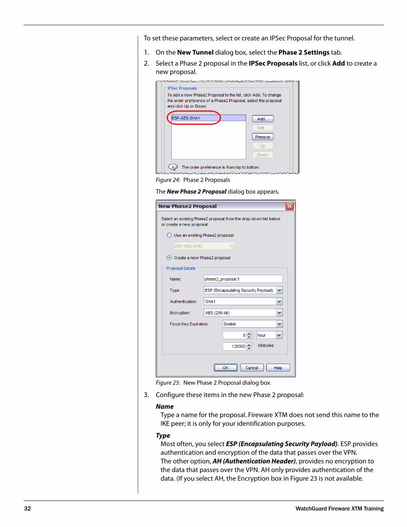
To set these parameters, select or create an IPSec Proposal for the tunnel.
1. On the New Tunnel dialog box, select the Phase 2 Settings tab.
2. Select a Phase 2 proposal in the IPSec Proposals list, or click Add to create a new proposal.
Figure 24: Phase 2 Proposals
The New Phase 2 Proposal dialog box appears.
Figure 25: New Phase 2 Proposal dialog box
3. Configure these items in the new Phase 2 proposal:
NameType a name for the proposal. Fireware XTM does not send this name to the IKE peer; it is only for your identification purposes.
TypeMost often, you select ESP (Encapsulating Security Payload). ESP provides authentication and encryption of the data that passes over the VPN. The other option, AH (Authentication Header), provides no encryption to the data that passes over the VPN. AH only provides authentication of the data. (If you select AH, the Encryption box in Figure 23 is not available.
What You Should Know
33
Authentication Authentication ensures that the information received is exactly the same as the information sent.
You can use SHA1 or MD5 as the algorithm the peers use to authenticate IKE messages from each other. SHA1 is more secure.
Encryption Encryption keeps the data confidential.
You can select DES, 3DES, or AES with 128, 192, or 256-bit key strength. AES is the most secure.
Force Key Expiration To make sure that Phase 2 encryption keys change periodically, always enable key expiration. The longer a Phase 2 encryption key is in use, the more data an attacker has for mounting an attack on the key.
Phase 2 expiration can happen based on the amount of time passed since the SA was created, the amount of data that goes over the VPN since the SA was created, or both. If you use 0 (zero) for either value, it means the Firebox or XTM device will disregard that limit. If you use both time and data as triggers for Phase 2 key expiration, the key is expired when the first event happens (time limit is reached or data limit is reached).
4. Click OK to save the new proposal.
5. Multicast over BOVPN Tunnel
In addition to Broadcast over BOVPN, Fireware XTM also introduces Multicast over BOVPN. This feature lets you extend multicast beyond your LAN and private networks. When you enable Multicast over BOVPN, you can configure your Firebox or XTM device to route multicast traffic through a BOVPN tunnel to another Firebox or XTM device.
Multicast supports one-way traffic streams from a sender at one end of the BOVPN tunnel to a receiver or group of receivers at the other end of the tunnel. The sender sends the multicast packets to the Firebox or XTM device through an internal interface such as the Trusted or Optional interface. When the Firebox or XTM device receives a multicast packet on the internal interface, it forwards it through the BOVPN tunnel. When the Firebox or XTM device at the other end of the tunnel receives the multicast packet, it forwards it to its internal interface. The actual receiving devices of the multicast packets must first associate themselves with a group IP address. This group IP address must be known on both ends of the tunnel.
34 WatchGuard Fireware XTM Training
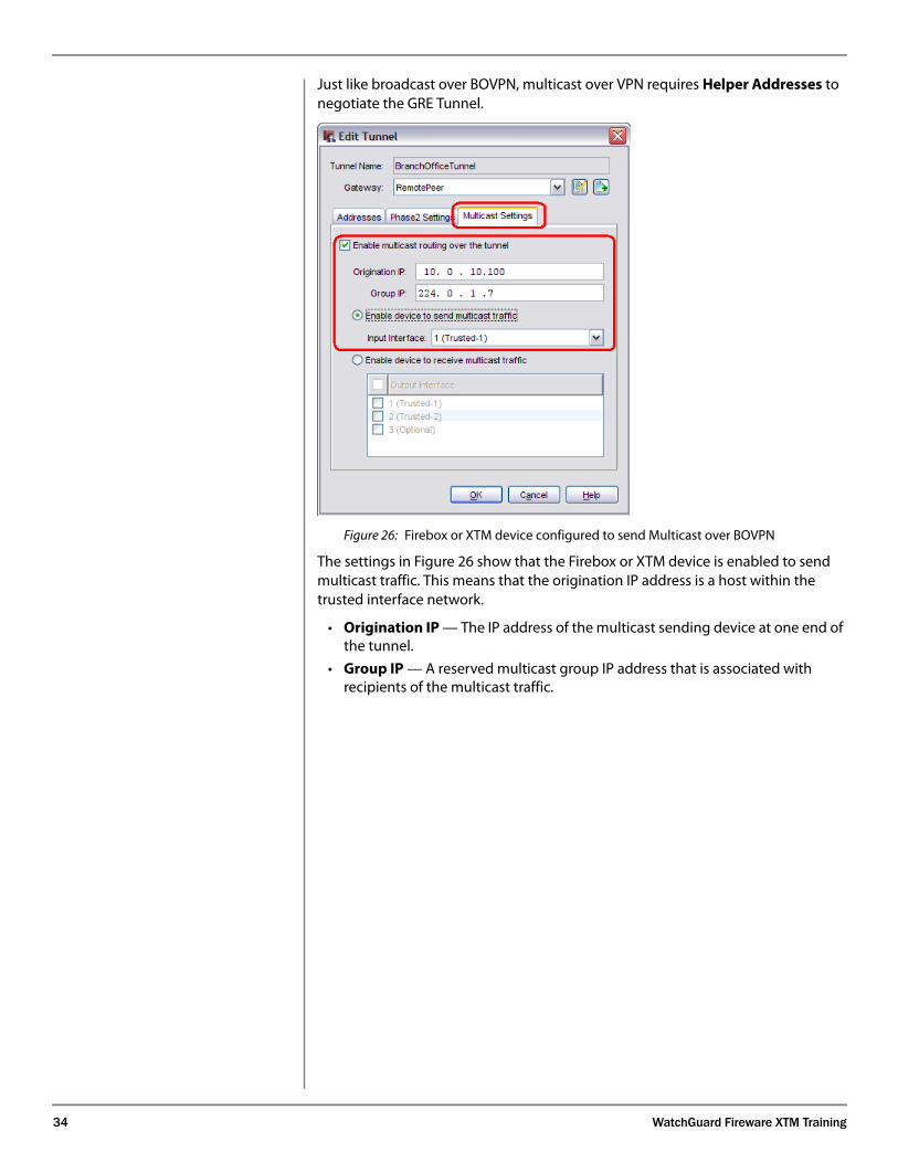
Just like broadcast over BOVPN, multicast over VPN requires Helper Addresses to negotiate the GRE Tunnel.
Figure 26: Firebox or XTM device configured to send Multicast over BOVPN
The settings in Figure 26 show that the Firebox or XTM device is enabled to send multicast traffic. This means that the origination IP address is a host within the trusted interface network.
• Origination IP — The IP address of the multicast sending device at one end of the tunnel.
• Group IP — A reserved multicast group IP address that is associated with recipients of the multicast traffic.
What You Should Know
35
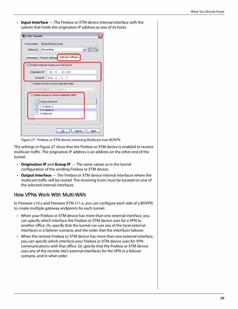
• Input Interface — The Firebox or XTM device internal interface with the subnet that holds the origination IP address as one of its hosts.
Figure 27: Firebox or XTM device receiving Multicast over BOVPN
The settings in Figure 27 show that the Firebox or XTM device is enabled to receive multicast traffic. The origination IP address is an address on the other end of the tunnel.
• Origination IP and Group IP — The same values as in the tunnel configuration of the sending Firebox or XTM device.
• Output Interface — The Firebox or XTM device internal interfaces where the multicast traffic will be routed. The receiving hosts must be located on one of the selected internal interfaces.
How VPNs Work With Multi-WAN In Fireware v10.x and Fireware XTM v11.x, you can configure each side of a BOVPN to create multiple gateway endpoints for each tunnel.
• When your Firebox or XTM device has more than one external interface, you can specify which interface the Firebox or XTM device uses for a VPN to another office. Or, specify that the tunnel can use any of the local external interfaces in a failover scenario, and the order that the interfaces failover.
• When the remote Firebox or XTM device has more than one external interface, you can specify which interface your Firebox or XTM device uses for VPN communications with that office. Or, specify that the Firebox or XTM device uses any of the remote site’s external interfaces for the VPN in a failover scenario, and in what order.
36 WatchGuard Fireware XTM Training
What multi-WAN can do for your VPNsMultiple Internet connections provide these benefits to your VPNs:
• Redundancy — If one Internet gateway is down, the VPN peers automatically use a different gateway (VPN failover). When the preferred gateway is available again, the peers automatically use it (VPN failback).
• Stability — Connections that go through the VPN stay connected when VPN failover and failback occur.
• VPN traffic load distribution — You can specify which external interface to use for each VPN. For example, you can use a less expensive Internet connection for a VPN with a small amount of traffic, and a more expensive connection for a more critical VPN or one with more traffic.
How the Firebox or XTM device detects that the IPSec peer gateway is downThe Firebox or XTM device detects that the IPSec peer gateway is down in two ways:
• IKE keep-alives get no response
• Ethernet link failure is detected on an external interface
Using IPSec Certificates for the IKE CredentialsWhen you use certificates, make sure that both devices have correct time zone settings, and that their internal clocks have approximately the same time (no more than a few minutes different). Certificates are time-sensitive instruments. Certificates are valid for a specified time period (only after a specified beginning date and time and only before an ending date and time). If the time for one of the clocks is different by a large amount, IKE negotiations can fail because a certificate is not yet valid (the clock is set before the “Valid From” date) or is no longer valid (past the “Valid To” date).
A certificate is a document used to verify the identify of an unknown individual. For IKE negotiations, the unknown individual is the remote IKE peer. During Phase 1 negotiations, the two IKE peers exchange their certificates. If each device accepts its peer’s certificate, then each side trusts that the peer is actually who it claims to be.
A certificate is issued by a certification authority (CA), which is an entity that represents an organization you trust for this purpose. A certification authority also issues a certificate for itself, called the CA certificate.
When the CA issues a certificate to an entity, it guarantees that the entity is actually who the entity claims to be. The CA indicates this guarantee by signing the certificate it issues to the entity.
In a transaction between an entity with a certificate and another party, the certified entity presents its certificate to the other party as proof of its identity. Thus, any party that wants to accept the certificate must trust the certification authority that issued the certificate. You indicate your trust in the CA when you import the CA certificate to the Firebox or XTM device. You learn how to import certificates in the section “About certificates issued by a third-party certification authority” on page 38.
When the CA signs a client certificate, the client certificate and the CA certificate have a cryptographic relationship. Because the two certificates are cryptographically tied to each other, you must have the CA certificate to verify the client certificate.
To use certificates with a VPN, each gateway endpoint must have these certificates:
What You Should Know
37
Note that in many situations, the same CA issues the client certificate for both gateway devices. If this is the case, #1 and #3 are the same CA certificate and your Firebox or XTM device needs only two certificates: the CA certificate and the local device’s client certificate.
If the two gateway devices use certificates issued by different certification authorities, then each device needs two CA certificates: one from the CA that issued the local device’s certificate and one from the CA that issued the remote device’s certificate.
• The CA certificate from the certification authority that issued the certificate for the local device.
Your Firebox or XTM device must verify the client certificate for the local device (see the subsequent point). It does this with the CA certificate from the authority that issued the client certificate. Make sure you import the CA certificate before you import the client certificate. This enables the Firebox or XTM device to verify the client certificate.
• The client certificate for the local device.
For your Firebox or XTM device, this is the certificate that your Firebox or XTM device sends to its VPN peer. The peer device verifies this certificate by checking it against a CA certificate.
• The CA certificate from the certification authority that issued the remote device’s IPSec certificate.
When your Firebox or XTM device receives an IPSec certificate from its IKE peer, it must have a means ‘to verify the peer’s certificate. It does this with the CA certificate of the certification authority that signed the remote peer’s certificate.
Only client certificates show at the bottom of Figure 3. CA certificates do not show here. Use Firebox System Manager to see CA certificates.
The certificates that this Firebox or XTM device can use to prove its identity appear in New Gateway dialog box in the Select the certificate to be used for the Gateway list. Items in this list can be certificates that were issued by a WatchGuard Management Server or by a third-party certification authority.
The WatchGuard Management Server issues IPSec certificates only for Firebox III, Firebox X Core, Firebox X Peak, and WatchGuard XTM devices. The Firebox SOHO 6 and Firebox X Edge cannot use certificates for VPNs.
About certificates issued by the WatchGuard Management Server
The WatchGuard Management Server is an optional component of the WatchGuard System Manager (WSM) software. When you install the WatchGuard Management Server, you install a server that lets you easily manage the VPNs for many Firebox or XTM devices. This also installs a certification authority, called the WatchGuard Certificate Authority, to issue and verify certificates for the managed client devices.
NoteIf your Firebox or XTM device is a managed client of a WatchGuard Management Server, you will probably use the Management Server to make managed VPNs. You cannot make managed VPNs with Policy Manager. Instead you use the Management Server to make managed VPNs between managed devices. The Management Server writes the VPN information to Policy Manager for each device, so that you can see the managed VPN in Policy Manager.
However, you cannot alter the managed VPN information with Policy Manager.
Using the Management Server to make VPNs is not a part of this training.
If you choose not to make a managed VPN between two managed Firebox or XTM devices, you can use Policy Manager to make a VPN between them manually. You can use the certificates issued by the Management Server when you create a manual VPN.
The WatchGuard Management Server automatically sends an IPSec certificate to the managed Firebox or XTM device, and it will appear at the bottom of the New Gateway dialog box. You can use this certificate to make a VPN to another Firebox or XTM device if both devices are managed by the same WatchGuard Management Server. The Management Server also automatically sends each managed Firebox or XTM device the CA certificate so that each Firebox or XTM device can verify the certificate that its peer sends in Phase 1. You do not manually import any certificates (described in the next section) if you use these certificates.
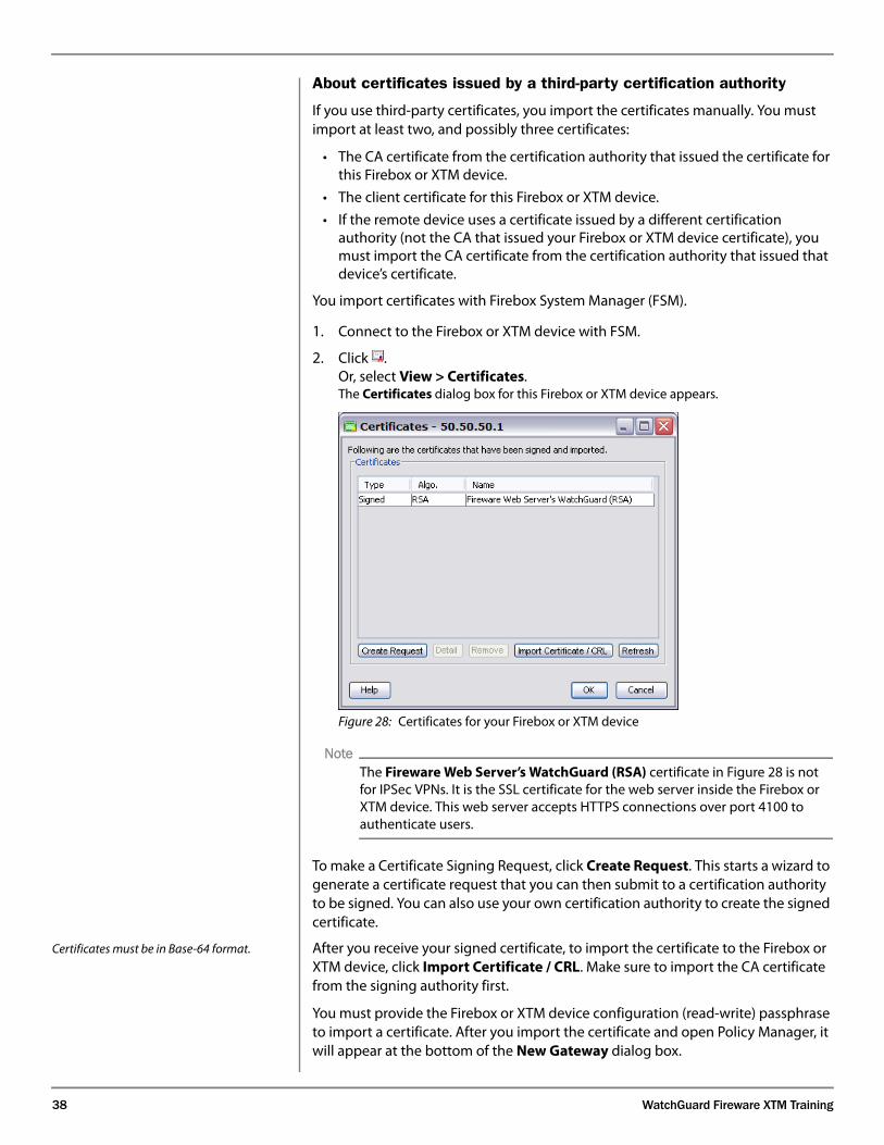
38 WatchGuard Fireware XTM Training
About certificates issued by a third-party certification authority
If you use third-party certificates, you import the certificates manually. You must import at least two, and possibly three certificates:
• The CA certificate from the certification authority that issued the certificate for this Firebox or XTM device.
• The client certificate for this Firebox or XTM device.
• If the remote device uses a certificate issued by a different certification authority (not the CA that issued your Firebox or XTM device certificate), you must import the CA certificate from the certification authority that issued that device’s certificate.
You import certificates with Firebox System Manager (FSM).
1. Connect to the Firebox or XTM device with FSM.
2. Click .Or, select View > Certificates.The Certificates dialog box for this Firebox or XTM device appears.
Figure 28: Certificates for your Firebox or XTM device
NoteThe Fireware Web Server’s WatchGuard (RSA) certificate in Figure 28 is not for IPSec VPNs. It is the SSL certificate for the web server inside the Firebox or XTM device. This web server accepts HTTPS connections over port 4100 to
authenticate users.
To make a Certificate Signing Request, click Create Request. This starts a wizard to generate a certificate request that you can then submit to a certification authority to be signed. You can also use your own certification authority to create the signed certificate.
Certificates must be in Base-64 format. After you receive your signed certificate, to import the certificate to the Firebox or XTM device, click Import Certificate / CRL. Make sure to import the CA certificate from the signing authority first.
You must provide the Firebox or XTM device configuration (read-write) passphrase to import a certificate. After you import the certificate and open Policy Manager, it will appear at the bottom of the New Gateway dialog box.
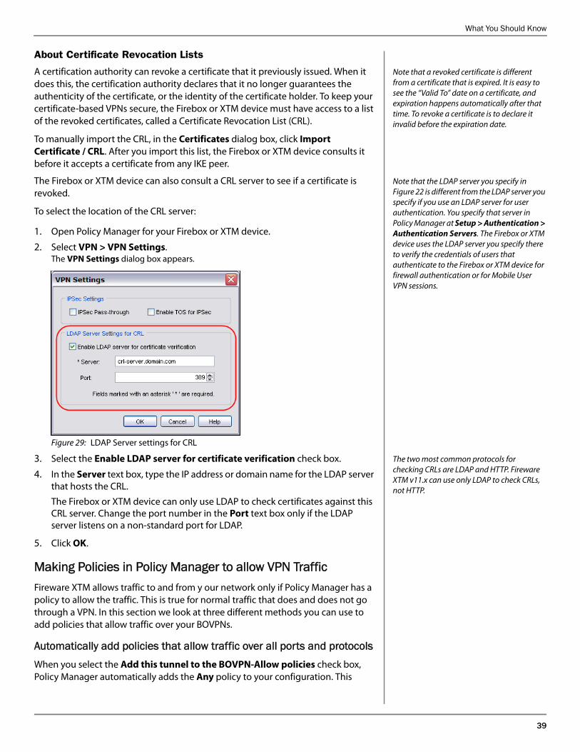
What You Should Know
39
About Certificate Revocation Lists
Note that a revoked certificate is different from a certificate that is expired. It is easy to see the “Valid To” date on a certificate, and expiration happens automatically after that time. To revoke a certificate is to declare it invalid before the expiration date.
A certification authority can revoke a certificate that it previously issued. When it does this, the certification authority declares that it no longer guarantees the authenticity of the certificate, or the identity of the certificate holder. To keep your certificate-based VPNs secure, the Firebox or XTM device must have access to a list of the revoked certificates, called a Certificate Revocation List (CRL).
To manually import the CRL, in the Certificates dialog box, click Import Certificate / CRL. After you import this list, the Firebox or XTM device consults it before it accepts a certificate from any IKE peer.
Note that the LDAP server you specify in Figure 22 is different from the LDAP server you specify if you use an LDAP server for user authentication. You specify that server in Policy Manager at Setup > Authentication > Authentication Servers. The Firebox or XTM device uses the LDAP server you specify there to verify the credentials of users that authenticate to the Firebox or XTM device for firewall authentication or for Mobile User VPN sessions.
The Firebox or XTM device can also consult a CRL server to see if a certificate is revoked.
To select the location of the CRL server:
1. Open Policy Manager for your Firebox or XTM device.
2. Select VPN > VPN Settings.The VPN Settings dialog box appears.
Figure 29: LDAP Server settings for CRL
The two most common protocols for checking CRLs are LDAP and HTTP. Fireware XTM v11.x can use only LDAP to check CRLs, not HTTP.
3. Select the Enable LDAP server for certificate verification check box.
4. In the Server text box, type the IP address or domain name for the LDAP server that hosts the CRL.
The Firebox or XTM device can only use LDAP to check certificates against this CRL server. Change the port number in the Port text box only if the LDAP server listens on a non-standard port for LDAP.
5. Click OK.
Making Policies in Policy Manager to allow VPN TrafficFireware XTM allows traffic to and from y our network only if Policy Manager has a policy to allow the traffic. This is true for normal traffic that does and does not go through a VPN. In this section we look at three different methods you can use to add policies that allow traffic over your BOVPNs.
Automatically add policies that allow traffic over all ports and protocolsWhen you select the Add this tunnel to the BOVPN-Allow policies check box, Policy Manager automatically adds the Any policy to your configuration. This
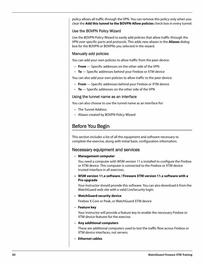
40 WatchGuard Fireware XTM Training
policy allows all traffic through the VPN. You can remove this policy only when you clear the Add this tunnel to the BOVPN-Allow policies check box in every tunnel.
Use the BOVPN Policy WizardUse the BOVPN Policy Wizard to easily add policies that allow traffic through the VPN over specific ports and protocols. This adds new aliases in the Aliases dialog box for the BOVPN or BOVPNs you selected in the wizard.
Manually add policiesYou can add your own policies to allow traffic from the peer device:
• From — Specific addresses on the other side of the VPN
• To — Specific addresses behind your Firebox or XTM device
You can also add your own policies to allow traffic to the peer device:
• From — Specific addresses behind your Firebox or XTM device
• To — Specific addresses on the other side of the VPN
Using the tunnel name as an interfaceYou can also choose to use the tunnel name as an interface for:
• The Tunnel Address
• Aliases created by BOVPN Policy Wizard
Before You Begin
This section includes a list of all the equipment and software necessary to complete the exercise, along with initial basic configuration information.
Necessary equipment and services• Management computer
You need a computer with WSM version 11.x installed to configure the Firebox or XTM device. This computer is connected to the Firebox or XTM device trusted interface in all exercises.
• WSM version 11.x software / Fireware XTM version 11.x software with a Pro upgrade
Your instructor should provide this software. You can also download it from the WatchGuard web site with a valid LiveSecurity login.
• WatchGuard security device
Firebox X Core or Peak, or WatchGuard XTM device
• Feature key
Your instructor will provide a feature key to enable the necessary Firebox or XTM device features for the exercise.
• Any additional computers
These are additional computers used to test the traffic flow across Firebox or XTM device interfaces, not servers.
• Ethernet cables
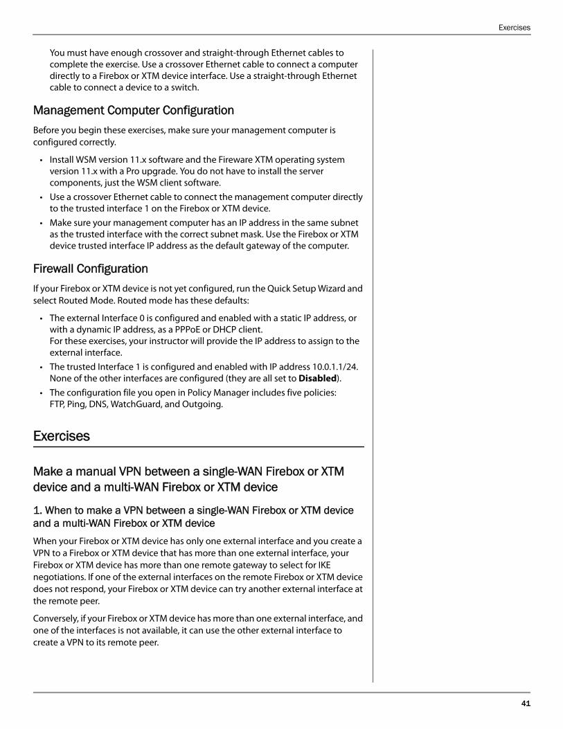
Exercises
41
You must have enough crossover and straight-through Ethernet cables to complete the exercise. Use a crossover Ethernet cable to connect a computer directly to a Firebox or XTM device interface. Use a straight-through Ethernet cable to connect a device to a switch.
Management Computer ConfigurationBefore you begin these exercises, make sure your management computer is configured correctly.
• Install WSM version 11.x software and the Fireware XTM operating system version 11.x with a Pro upgrade. You do not have to install the server components, just the WSM client software.
• Use a crossover Ethernet cable to connect the management computer directly to the trusted interface 1 on the Firebox or XTM device.
• Make sure your management computer has an IP address in the same subnet as the trusted interface with the correct subnet mask. Use the Firebox or XTM device trusted interface IP address as the default gateway of the computer.
Firewall ConfigurationIf your Firebox or XTM device is not yet configured, run the Quick Setup Wizard and select Routed Mode. Routed mode has these defaults:
• The external Interface 0 is configured and enabled with a static IP address, or with a dynamic IP address, as a PPPoE or DHCP client. For these exercises, your instructor will provide the IP address to assign to the external interface.
• The trusted Interface 1 is configured and enabled with IP address 10.0.1.1/24.None of the other interfaces are configured (they are all set to Disabled).
• The configuration file you open in Policy Manager includes five policies: FTP, Ping, DNS, WatchGuard, and Outgoing.
Exercises
Make a manual VPN between a single-WAN Firebox or XTM device and a multi-WAN Firebox or XTM device
1. When to make a VPN between a single-WAN Firebox or XTM device and a multi-WAN Firebox or XTM deviceWhen your Firebox or XTM device has only one external interface and you create a VPN to a Firebox or XTM device that has more than one external interface, your Firebox or XTM device has more than one remote gateway to select for IKE negotiations. If one of the external interfaces on the remote Firebox or XTM device does not respond, your Firebox or XTM device can try another external interface at the remote peer.
Conversely, if your Firebox or XTM device has more than one external interface, and one of the interfaces is not available, it can use the other external interface to create a VPN to its remote peer.
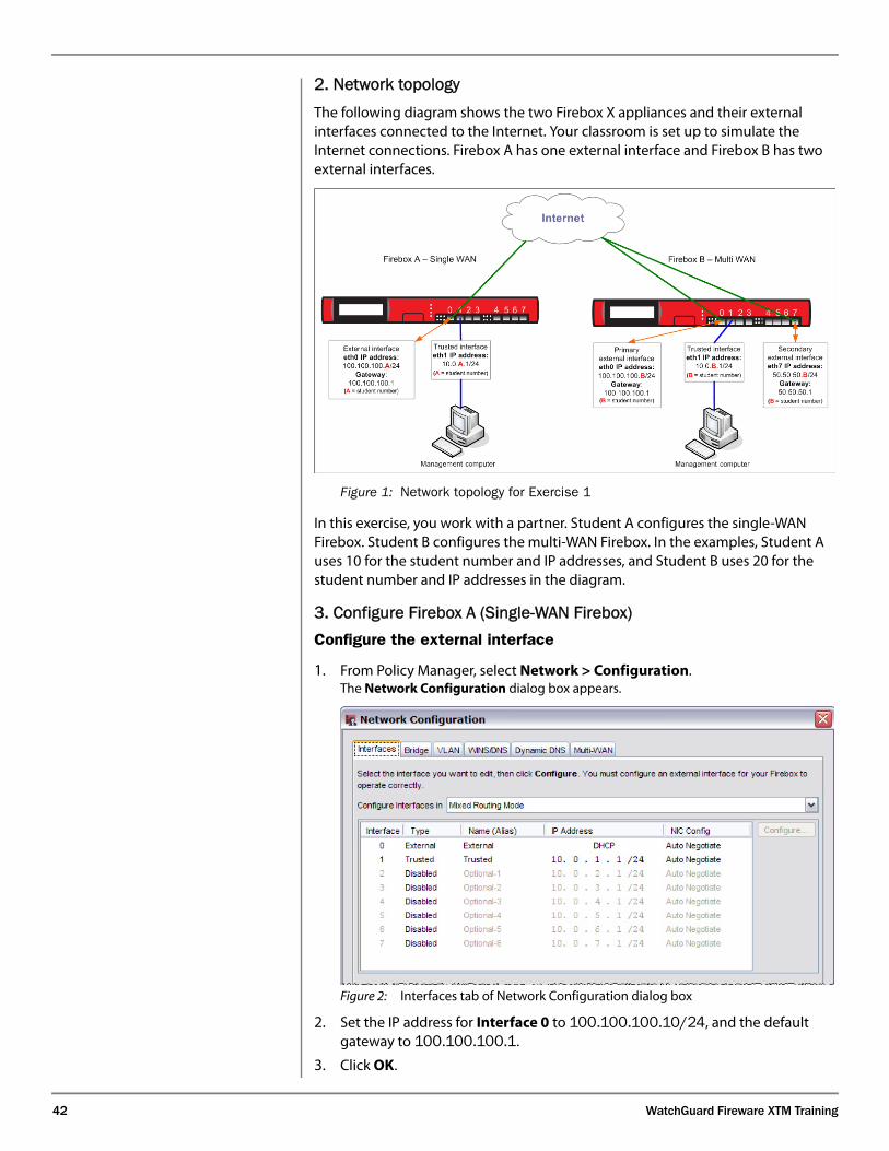
42 WatchGuard Fireware XTM Training
2. Network topologyThe following diagram shows the two Firebox X appliances and their external interfaces connected to the Internet. Your classroom is set up to simulate the Internet connections. Firebox A has one external interface and Firebox B has two external interfaces.
Figure 1: Network topology for Exercise 1
In this exercise, you work with a partner. Student A configures the single-WAN Firebox. Student B configures the multi-WAN Firebox. In the examples, Student A uses 10 for the student number and IP addresses, and Student B uses 20 for the student number and IP addresses in the diagram.
3. Configure Firebox A (Single-WAN Firebox)Configure the external interface
1. From Policy Manager, select Network > Configuration.The Network Configuration dialog box appears.
Figure 2: Interfaces tab of Network Configuration dialog box
2. Set the IP address for Interface 0 to 100.100.100.10/24, and the default gateway to 100.100.100.1.
3. Click OK.
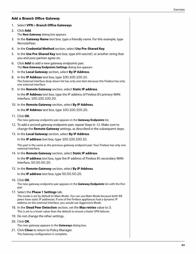
Exercises
43
Add a Branch Office Gateway
1. Select VPN > Branch Office Gateways.
2. Click Add.The New Gateway dialog box appears.
3. In the Gateway Name text box, type a friendly name. For this example, type RemotePeer.
4. In the Credential Method section, select Use Pre-Shared Key.
5. In the Use Pre-Shared Key text box, type shh-secret!, or another string that you and your partner agree on.
6. Click Add to add a new gateway endpoints pair.The New Gateway Endpoints Settings dialog box appears.
7. In the Local Gateway section, select By IP Address.
8. In the IP Address text box, type 100.100.100.10.The External Interface drop-down list has only one item because this Firebox has only one external interface.
9. In the Remote Gateway section, select Static IP address.
In the IP Address text box, type the IP address of Firebox B’s primary WAN interface, 100.100.100.20.
10. In the Remote Gateway section, select By IP Address.
In the IP Address text box, type 100.100.100.20.
11. Click OK. The new gateway endpoints pair appears in the Gateway Endpoints list.
12. To add a second gateway endpoints pair, repeat Steps 6–12. Make sure to change the Remote Gateway settings, as described in the subsequent steps.
13. In the Local Gateway section, select By IP Address.
In the IP address text box, type 100.100.100.10.
This part is the same as the previous gateway endpoint pair. Your Firebox has only one external interface.
14. In the Remote Gateway section, select Static IP address.
In the IP address text box, type the IP address of Firebox B’s secondary WAN interface, 50.50.50.20.
15. In the Remote Gateway section, select By IP Address.
In the IP address text box, type 50.50.50.20.
16. Click OK. The new gateway endpoints pair appears in the Gateway Endpoints list with the first pair.
17. Select the Phase 1 Settings tab. The mode is set by default to Main Mode. You can use Main Mode because both IKE peers have static IP addresses. If one of the Firebox appliances had a dynamic IP address on the external interface, you would use Aggressive Mode.
18. In the Dead Peer Detection section, set the Max retries value to 3.This is set to a lower value than the default to ensure a faster VPN failover.
19. Do not change the other settings.
20. Click OK. The new gateway appears in the Gateways dialog box.
21. Click Close to return to Policy Manager.The Gateway configuration is complete.
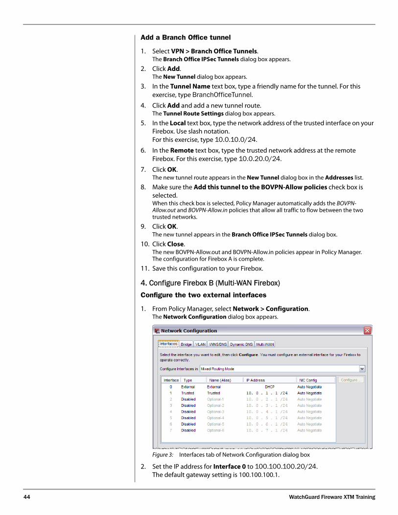
44 WatchGuard Fireware XTM Training
Add a Branch Office tunnel
1. Select VPN > Branch Office Tunnels. The Branch Office IPSec Tunnels dialog box appears.
2. Click Add.The New Tunnel dialog box appears.
3. In the Tunnel Name text box, type a friendly name for the tunnel. For this exercise, type BranchOfficeTunnel.
4. Click Add and add a new tunnel route.The Tunnel Route Settings dialog box appears.
5. In the Local text box, type the network address of the trusted interface on your Firebox. Use slash notation. For this exercise, type 10.0.10.0/24.
6. In the Remote text box, type the trusted network address at the remote Firebox. For this exercise, type 10.0.20.0/24.
7. Click OK. The new tunnel route appears in the New Tunnel dialog box in the Addresses list.
8. Make sure the Add this tunnel to the BOVPN-Allow policies check box is selected. When this check box is selected, Policy Manager automatically adds the BOVPN-Allow.out and BOVPN-Allow.in policies that allow all traffic to flow between the two trusted networks.
9. Click OK.The new tunnel appears in the Branch Office IPSec Tunnels dialog box.
10. Click Close.The new BOVPN-Allow.out and BOVPN-Allow.in policies appear in Policy Manager.The configuration for Firebox A is complete.
11. Save this configuration to your Firebox.
4. Configure Firebox B (Multi-WAN Firebox)Configure the two external interfaces
1. From Policy Manager, select Network > Configuration.The Network Configuration dialog box appears.
Figure 3: Interfaces tab of Network Configuration dialog box
2. Set the IP address for Interface 0 to 100.100.100.20/24.The default gateway setting is 100.100.100.1.
Exercises
45
3. Double-click Interface 7 and edit it.
4. In the Interface Type drop-down list, select External.
5. In the Interface Name (Alias) text box, type a new name for the interface. For this example, type WAN2.
6. Select Use Static IP.
7. In the IP address text box, type 50.50.50.20/24.
8. In the Default Gateway text box, type 50.50.50.1.
9. Click OK to return to Policy Manager.
Add a Branch Office Gateway
1. Select VPN > Branch Office Gateways.
2. Click Add.
3. In the Gateway Name text box, type a friendly name for the gateway. For this example, type RemotePeer.
4. In the Credential Method section, select Use Pre-Shared Key.
5. In the Use Pre-Shared Key text box, type sshh-secret!, or another string that you and your partner agree on.
6. Click Add.The New Gateway Endpoints Settings dialog box appears.
7. In the Local Gateway section, select By IP Address.
In the IP address text box, type 100.100.100.20.
8. From the External Interface drop-down list, select External.External is the default name for interface 0. If you changed the name of interface 0, select that name.
9. In the Remote Gateway section, select Static IP address.
In the IP address text box, type the IP address of Firebox B’s primary WAN interface, 100.100.100.10.
10. In the Remote Gateway section, select By IP Address.
In the IP address text box, type 100.100.100.10.
11. Click OK.The new gateway endpoints pair appears in the Gateway Endpoints list.
12. To add a second gateway endpoints pair, repeat Steps 6–12. Make sure to change the Local Gateway settings, as described in the subsequent steps.
13. In the Local Gateway section, select By IP Address.
In the IP address text box, type 50.50.50.20.
14. From the External Interface drop-down list, select WAN2.This is the most common place to make an error. Make sure to select the interface name that corresponds to the secondary WAN interface on this Firebox.
15. In the Remote Gateway section, select Static IP address.
In the IP address text box, type the IP address of Firebox B’s secondary WAN interface, 100.100.100.10.
These settings do not change from the previous gateway endpoint pair you added. The remote Firebox has only one external interface.
16. In the Remote Gateway section, select By IP Address.
In the IP address text box, type 100.100.100.10.
46 WatchGuard Fireware XTM Training
17. Click OK. The new gateway endpoints pair appears in the Gateway Endpoints list with the first pair.
18. Click the Phase 1 Settings tab. The mode is set by default to Main Mode. You can use Main Mode because both IKE peers have static IP addresses. If one of the Firebox appliances had a dynamic IP address on the external interface, use Aggressive Mode.
19. In the Dead Peer Detection section, set the Max retries value to 3.This is set to a lower value than the default to ensure a faster VPN failover.
20. Do not change the other settings.
21. Click OK. The new gateway appears in the Gateways dialog box.
22. Click Close to return to Policy Manager.The Gateway configuration is complete.
Add a Branch Office tunnel
1. Select VPN > Branch Office Tunnels. The Branch Office IPSec Tunnels dialog box appears.
2. Click Add.The New Tunnel dialog box appears.
3. In the Tunnel Name text box, type a friendly name for the tunnel. For this exercise, type BranchOfficeTunnel.
4. Click Add and add a new tunnel route.The Tunnel Route Settings dialog box appears.
5. In the Local text box, type the network address of the trusted interface on your Firebox. Use slash notation. For this exercise, type 10.0.20.0/24.
6. In the Remote text box, type the trusted network address at the remote Firebox, 10.0.10.0/24.
7. Click OK. The new tunnel route appears in the Addresses list.
8. Make sure the Add this tunnel to the BOVPN-Allow policies check box is selected.When this option is selected, Policy Manager automatically adds the BOVPN-Allow.out and BOVPN-Allow.in policies to your configuration. These policies allow all traffic to flow between the two trusted networks.
9. Click OK.The new tunnel appears in the Branch Office IPSec Tunnels dialog box.
10. Click Close. The new BOVPN-Allow.out and BOVPN-Allow.in policies appearThe configuration for Firebox B is complete.
11. Save this configuration to your Firebox.
5. Physically Connect all DevicesBoth appliances
1. Connect one end of an Ethernet cable to the Firebox Interface 0.
2. Connect the other end of this Ethernet cable to the hub or switch that connects to the 100.100.100.x network.
Appendix
47
Firebox B
1. Connect one end of an Ethernet cable to the Firebox Interface 7.
2. Connect the other end of this Ethernet cable to the hub or switch that connects to the 50.50.50.x network.
6. Demonstrate the configuration
1. Get the IP address of your partner’s management computer.
2. Start a continuous ping to that address.
For example, if your partner’s management computer IP address is 10.0.20.2, open a command prompt and type: ping 10.0.20.2 -t
3. Disconnect interface 0 on Firebox B
The Firebox appliances start new IKE negotiations with Firebox B’s secondary WAN interface. Only one to three pings should time out.
Appendix
Here is a typical sequence of log messages for a Main Mode VPN between two Firebox or XTM device appliances running Fireware XTM 11.x with a Pro upgrade. The Diagnostic Log Level for IKE is set to High.
Logs from Firebox or XTM device with external IP address 192.168.54.61
Starting phase 1 negotiation using [Box64] to 192.168.54.64:500
main mode
Received second message with policy [Box64] from 192.168.54.64:500
main mode
Sending third message to 192.168.54.64:500 main mode
Received fourth message with policy [Box64] from 192.168.54.64:500
main mode
Sending fifth message with policy [Box64] to 192.168.54.64:500 main
mode
Received sixth message with policy [Box64] from 192.168.54.64:500
main mode
Phase 1 completed as initiator
MM hash_alg=2 encr_alg=5 auth_alg=1 dh_group=1 seconds=28797
kbytes=0
Sending INITIAL_CONTACT message to 192.168.54.64:500,
mess_id=0x5e6321aa
Starting phase 2 to 192.168.54.64:500 quick mode message (id
969e4ee2)
Received second message(id 969e4ee2) from 192.168.54.64:500 quick
mode
Received the SA responder_lifetime message from 192.168.54.64
Sending to 192.168.54.64:500 quick mode third message(id 969e4ee2)
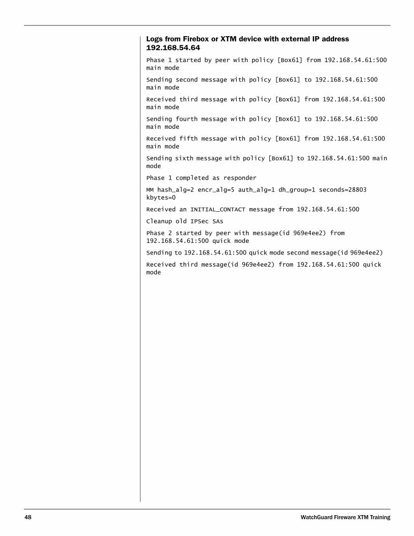
48 WatchGuard Fireware XTM Training
Logs from Firebox or XTM device with external IP address 192.168.54.64
Phase 1 started by peer with policy [Box61] from 192.168.54.61:500
main mode
Sending second message with policy [Box61] to 192.168.54.61:500
main mode
Received third message with policy [Box61] from 192.168.54.61:500
main mode
Sending fourth message with policy [Box61] to 192.168.54.61:500
main mode
Received fifth message with policy [Box61] from 192.168.54.61:500
main mode
Sending sixth message with policy [Box61] to 192.168.54.61:500 main
mode
Phase 1 completed as responder
MM hash_alg=2 encr_alg=5 auth_alg=1 dh_group=1 seconds=28803
kbytes=0
Received an INITIAL_CONTACT message from 192.168.54.61:500
Cleanup old IPSec SAs
Phase 2 started by peer with message(id 969e4ee2) from
192.168.54.61:500 quick mode
Sending to 192.168.54.61:500 quick mode second message(id 969e4ee2)
Received third message(id 969e4ee2) from 192.168.54.61:500 quick
mode
Frequently Asked Questions
49
Frequently Asked Questions
What if my Firebox or XTM device has a private IP address on the external interface? A private IP address is an address from one of the three ranges defined in RFC-1918. These addresses are sometimes called non-routable addresses, because they are not allowed to be routed by public Internet routers. The private address ranges are:
• 10.0.0.0/8 [10.0.0.1–10.255.255.254]
• 172.16.0.0/12 [172.16.0.1–172.31.255.254]
• 192.168.0.0/16 [192.168.0.0–192.168.255.254]
In this situation, it is likely that your Firebox or XTM device is behind a device that does NAT. Whether your Firebox or XTM device can make a BOVPN to another device depends on the type of NAT this device uses. Most devices today have an IPSec pass-through option. Make sure to enable this option on the NAT device.
After you enable the IPSec pass-through option on the NAT device, you must still decide how your Firebox or XTM device identifies itself to the remote device. You have several options:
• One way to configure the local gateway for the gateway endpoints is to select By Domain Information.
- If the NAT device has an IP address that can be resolved by DNS query of a domain name, then the remote device can find your device by domain name. Use the fully qualified domain name that resolves to the public IP address on the external interface of the NAT device.
- If there is no domain name that resolves to an IP address for the NAT device, you can still use By Domain Information. However, because the remote device cannot find your device, this means that your device must always be the initiator.
• You may be able to select By IP Address for the local gateway in the gateway endpoints settings. The IP address for the local gateway must match the source IP address that the remote device sees for packets coming from this Firebox or XTM device. If your Firebox or XTM device is behind a device that applies NAT to outgoing packets, the remote device sees the source of your Firebox or XTM device’s packets as the IP address on the NAT device. If this is the case, and if the NAT device has a static public IP address, you can type the public IP address on the Internet-facing interface of the NAT device for the IP address of the local gateway for the gateway endpoints settings.
If the IP address on the NAT device is dynamic, you must select By Domain Information for the local gateway in the gateway endpoints settings.

TRAININGwww.watchguard.com/[email protected]
COPYRIGHT © 2010 WatchGuard Technologies, Inc. All rights reserved.WatchGuard, the WatchGuard logo, Firebox, and Core are registered trademarks or trademarks of WatchGuard Technologies, Inc. in the United States and/or other countries.
What You Have Learned
You have learned:
• What happens in IPSec Phase 1.
• What happens in IPSec Phase 2.
• How to enable broadcast routing over a VPN.
• How to create a VPN tunnel between a single-WAN Firebox or XTM device and a multi-WAN Firebox or XTM device.
• How VPN failover works.