Embed Size (px)
Citation preview

Student Engineer Work Program Induction Guide - Mechanical and Piping Engineering
CONTENTS 1. Objective................................................................................................................ 1
1.1 Outcomes ............................................................................................................ 1
2. Schedule................................................................................................................ 2
3. Work Structure...................................................................................................... 3
3.1 Training Elements ................................................................................................. 3
3.1.1 Core Elements ................................................................................................. 3
3.1.2 Elective Elements ............................................................................................ 4
3.1.3 Alternative Elements ........................................................................................ 9
3.2 Feedback ............................................................................................................. 9
3.3 Work Dossier.......................................................................................................10
3.4 Work Presentation ...............................................................................................10
4. Conclusion...........................................................................................................11
Appendices
Core Element 1: Understanding the Business
Core Element 2: Introduction to Engineering
Core Element 3: Project Document Types
Elective Element 1: Pressure Vessels
Elective Element 2: Heat Exchangers
Elective Element 3: Pump Basics
Elective Element 4: Compressor/Turbine Basics
Elective Element 5: Materials Handling Basics
Elective Element 6: Materials Selection Basics
Elective Element 7: Manning and Maintenance
Elective Element 8: Piping Hydraulic Design
Elective Element 9: Piping Mechanical Design
Elective Element 10: Bulk Materials Handling Equipment
Elective Element 11: Mineral Processing Equipment
Elective Element 12: 3D Design Workflow
Elective Element 13: SP Item List
Elective Element 14: Piping Materials Specification
Page ii

Elective Element 15: Compressor/Turbine Basics - Piping
Elective Element 16: Material Selection Basics
Elective Element 17 Piping Design
Page iii
1. OBJECTIVE
The aim of the program is to provide the student engineer with an appreciation of the engineering culture in this organisation by establishing a structured program.
The typical duration of the program is 12 weeks, generally between the months of November and March for students studying in Australia.
1.1 Outcomes
Upon completion of the work program, the student engineer is expected to develop skills in the following areas:
Technical competencies – understand the basic requirements of engineers in the workplace;
Business acumen – understand the role of this organisation as a business;
Teamwork and communication – understand team dynamics on a project and within the organisation; and
Self-management – understand the importance of structured work and time management.
The program is structured as a systematic tool for guiding and monitoring the student engineer’s performance.
Page 1
2. SCHEDULE
The schedule presented below acts only as a guide and actual timeframes may vary. The supervising engineer will monitor progress on a regular basis and adjust the work program to suit. The student engineer will:
Week 1 to Week 10 – Gain relevant knowledge/experience and compile work dossier on regular basis.
Week 11 – Submit work dossier to supervising engineer. Prepare presentation to discipline team.
Week 12 – Present summary of work program.
The initial 10 weeks of the program focus on technical training and the final 2 weeks will concentrate on developing communication and presentation skills.
Page 2
3. WORK STRUCTURE
The student engineer is expected to undertake a combination of project-based work and supplementary training activities to satisfy the requirements of the work program. Project-based work is the preferred option but depends on the status of the project and suitable workload for the student engineer. The supplementary training activities are designed to cover the competencies that project-based work cannot offer.
3.1 Training Elements
The following set of training elements are to be completed in the agreed engagement duration and compiled into a work dossier for submission. These elements can be completed using either project-based work or supplementary training activities as discussed previously.
The student engineer is required to address 3 compulsory core elements and 3 elective elements. The elective elements are designed to allow the student to increase their knowledge in an area of relevance to their project work or in an area of particular interest.
3.1.1 Core Elements
All core elements are compulsory and must be addressed. The total time proposed for the completion of all core elements is four weeks.
3. 1.1. 1 Core Element 1 – Understandi ng the Business
Role of Client, Contractor and Sub-contractors
Type of projects
Project phases
Engineering functions
Standard lifecycle of a project
3. 1.1. 2 Core Element 2 – Introduction to Engineering
Basis of Design (BOD), Project Execution Plan (PEP), Engineering Execution Plan (EEP)
Types of disciplines
Process drawings: Process Flow Diagram (PFD), Piping and Instrumentation Diagram (P&ID)
Mechanical drawings: General arrangements, layout plans, elevations, details, assemblies, isometrics, fabrication
Equipment List
Piping Line List, Valve List, Tie In List
3. 1.1. 3 Core Element 3 – Project Document Types
Basis of Design
Scope of Work / Planning / CTRs
Study/Reports (Technical Notes)
Page 3
Technical Specifications
Data Sheets
Material Requisitions (RFQs)
Technical Bid Evaluations
Purchase Requisitions
Supplier Documents and Drawings Review / Approval
3.1.2 Elective Elements
The student engineer must select at least three elements from the available set which apply to his/her group and project situation. The total time proposed for the completion of these elements is six weeks. Therefore, the period between Week 5 and Week 10 will focus on the three elements chosen.
The following elements are common to Hydrocarbons and Minerals and Metals:
• Elective Element 1 – Pressure Vessels
• Elective Element 2 – Heat Exchangers
• Elective Element 3 – Pump Basics
Only students working in Hydrocarbons may select from the following elective elements:
• Elective Element 4 – Compressor/Turbine Basics
• Elective Element 5 – Materials Handling Basics
• Elective Element 6 – Materials Selection Basics
• Elective Element 7 – Manning and Maintenance
Only students working in Minerals and Metals may select from the following elective elements:
• Elective Element 8 – Piping: Hydraulic Design
• Elective Element 9 – Piping: Mechanical Design
• Elective Element 10 – Bulk Materials Handling
• Elective Element 11 – Mineral Processing Equipment
The following element is common to Minerals and Metals and Piping (Hydrocarbons):
• Elective Element 12 – 3D Design Workflow
Only students working in Piping (Hydrocarbons) may select from the following elective elements:
• Elective Element 13 – SP Item List
• Elective Element 14 – Piping Materials Specification
• Elective Element 15 – Piping: Compressor/Turbine Basics
• Elective Element 16 – Piping: Materials Selection Basics
• Elective Element 17 – Piping: Design
The following table summarises the above list and may be used as a guide for the vacation student to determine what elements may be researched depending on the vacation student’s discipline:
Page 4
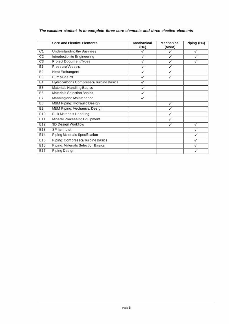
The vacation student is to complete three core elements and three elective elements
Core and Elective Elements Mechanical
(HC) Mechanical
(M&M) Piping (HC)
C1 Understanding the Business C2 Introduction to Engineering C3 Project Document Types E1 Pressure Vessels E2 Heat Exchangers E3 Pump Basics E4 Hydrocarbons Compressor/Turbine Basics E5 Materials Handling Basics E6 Materials Selection Basics E7 Manning and Maintenance E8 M&M Piping: Hydraulic Design E9 M&M Piping: Mechanical Design E10 Bulk Materials Handling E11 Mineral Processing Equipment E12 3D Design Workflow E13 SP Item List E14 Piping Materials Specification E15 Piping: Compressor/Turbine Basics E16 Piping: Materials Selection Basics E17 Piping Design
Page 5
3. 1.2. 1 Elective Element 1 – Pressure Vesse ls
Design codes – Australian standards, ASME and international standards
Issues determined by codes
Material choices and selection
Principal calculations required
Design rules and analysis
Inspection and testing
External loadings from attached piping, supports, wind, seismic and blast
How to specify a vessel for procurement
3. 1.2. 2 Elective Element 2 – Hea t Exchangers
Exchanger types and selection – Shell & Tube, Plate, Printed Circuit, Air Cooled
Design codes – Australian standards, TEMA and international standards
Issues determined by codes
Material choices and selection
Principal calculations required
Design rules and analysis
Inspection and testing
External loadings from attached piping, supports, wind, seismic and blast
How to specify a heat exchanger for procurement
3. 1.2. 3 Elective Element 3 – Pump Basics
Pump types and selection – Centrifugal, Positive Displacement, Metering, slurry
Design codes – API 610, ANSI and vendor standards.
Mechanical seal systems and selection
Materials of construction
3. 1.2. 4 Elective Element 4 – Compresso r/T ur bine Basics
Compressor types and selection – Centrifugal, Reciprocating
Turbine types and selection
Engine types and selection
Design codes – API 616, API 617, API 618
Seal systems and selection
Lube systems and selection
Page 6
3. 1.2. 5 Elective Element 5 – Mate ria ls Handling Basics
Onshore operational requirements
Offshore operational requirements
Pedestal Crane basic selection
3. 1.2. 6 Elective Element 6 – Mate ria ls Se lection Basics
Corrosion aspects of oil and gas
Basic material selection philosophy
3. 1.2. 7 Elective Element 7 – Manning and Ma intenance
Manning and maintenance studies/calculations
3. 1.2. 8 Elective Element 8 – Piping: Hydraul ic design
Moody Diagram and friction factor calculation
Pump types – centrifugal and other
Head loss due to fittings
Pipework pressure rating
Use of software package(s)
3. 1.2. 9 Elective Element 9 – Piping: Mechanica l Design
Design Codes – Australian Standards and ASME
Issues determined by codes
Material choices and selection
Valve types and selection
Supporting of pipework
3. 1.2. 10 Elective Element 10 – Bulk Mate ria ls Handling
Select two items from the list below.
Flow through bins
Feeders
Belt conveyors
Other bulk material conveyors
Principal calculations required
Wear resistant materials
3. 1.2. 11 Elective Element 11 – Minera l Processi ng Equipment
Select two items from the list below.
Crushing or screening
Page 7
Grinding
Flotation
Liquid-solid separation
Size classification
3. 1.2. 12 Elective Element 12 – 3D Design Workflow
Pre-requisites to start modelling
Indicative, primary and secondary equipment data.
Interdiscipline coordination and space allocation
Review and checking
Extraction and issue of deliverables
3. 1.2. 13 Elective Element 13 – SP I tem List
Production of an SP Item List
Design codes – Australian standards, ASME and international standards
Issues determined by codes
Material choices and selection
Principal calculations required
Design rules and analysis
Inspection and testing
How to specify an SP item for procurement
3. 1.2. 14 Elective Element 14 – Piping Mate ria l Specifica tion
Purpose of piping material specifications (line classes)
Design codes – Australian standards, TEMA and international standards
Issues determined by codes
Material choices and selection
Principal calculations required
Inspection and testing
3. 1.2. 15 Elective Element 15 – Compresso r/T ur bine Basics- Piping
Compressor types – Centrifugal, Reciprocating
Turbine types
Piping issues associated with compressors
Nozzle loads
Pipe supports
Page 8
3. 1.2. 16 Elective Element 16 – Mate ria ls Se lection Basics
Corrosion aspects of oil and gas
Basic material selection philosophy
3. 1.2. 17 Elective Element 17 – Piping Design
Design Codes – Australian Standards and ASME
Issues determined by codes
Material choices and selection
Valve types and selection
Supporting of pipework
3.1.3 Alternative Elements
The following elements provide valuable experience for a student engineer but are not catered for in the work program due to their unpredictable availability:
Project site visits
Fabrication yard site visits
3D plant model “walk” throughs
Vendor presentations
Organisation of social activities
Where applicable, the student engineer is expected to prepare a brief description on what they learned and observed from the experience. This provides feedback to the supervising engineer for future use.
3.2 Feedback
The student engineer is required to provide feedback on each section of the program and on their overall experience during vacation work with the organisation. This feedback shall be submitted formally in the final section of the work dossier and is expected to include discussion on the following points:
- Clarity in the description and expectations of the program
- Clarity of the description for each topic in the dossier
- Difficulty in sourcing materials to complete each topic
- Difficulty of exercises within each topic
- Recommended changes for each topic
- Any difficulties faced during work experience as a whole
- Best and worst aspects of the work experience
- Recommended changes for the program and work experience as a whole
Page 9
3.3 Work Dossier
It is recommended that the student engineer begin compiling their work dossier from day one. Each student engineer is expected to submit a work dossier to the supervising engineer upon completion of the training elements. As a guide, this is to occur during Week 11 as per the schedule in Section 2.
Upon completion of the dossier, the contents of the binder are to be scanned as per the divided section headings and stored electronically.
The state of the work dossier is an effective indicator of the individual’s performance. Therefore, it is expected that all work stored in the dossier will be of the student’s highest quality.
3.4 Work Presentation
The student engineer is required to organise and prepare a formal presentation addressing the discipline team. In general, the presentation is prepared as a summary of the work dossier. It will include a brief description of each training element completed and the project examples used. In addition, the presenter is encouraged to address their thoughts on the work program and areas for improvement.
Where applicable, the presentation will be prepared in groups of two. The two student engineers will discuss and agree on the material to be presented. Both are required to present on the day. The two presenters are encouraged to alternate between the presentation of training elements e.g. Presenter A talks about Core Element 1 and Presenter B talks about Core Element 2 and so on.
The standardised format for the presentation is an electronic file prepared in Microsoft Powerpoint. The file is to be stored electronically under
Hydrocarbons: [location removed]
Minerals and Metals: [location removed]
Piping: [location removed]
Page 10

4. CONCLUSION
As a continuing work program, it is recommended that the supervising engineers perform an exit interview to gain further feedback from the student engineers as this will improve the quality and success of the program. The valuable feedback gained can then be incorporated into future revisions.
Page 11
Core Element 1: Understanding the Business Introduction
This section aims to provide an understanding of the basic aspects of business in this organisation.
Reference Documents
None
Exercises
Discuss the following topics:
1. Role of client, contractor and sub-contractors
2. Different types of projects
3. Project phases
4. Engineering functions
5. Standard lifecycle of a project
Page 12
Core Element 2: Introduction to Engineering Introduction
This section aims to provide an understanding of the engineering practices and processes in this organisation.
Reference Documents
None
Exercises
1. Discuss the role and objective of the following documents in a project:
a. Basis of Design (BOD)
b. Project Execution Plan (PEP)
c. Engineering Execution Plan (EEP)
2. Describe the basic process flow for your project based on the Process Flow Diagram (PFD). Examine the Piping and Instrumentation Diagrams (P&IDs) with respect to the Process Flow Diagram to understand the role and content of the P&IDs and learn how to read these drawings.
3. Collect an example of each of the listed mechanical drawing types in section 3.1.1.2. Write a one sentence description for the typical content of each.
4. Provide a one-sentence description of each of the lists.
5. Describe the various discipline groups on your project and their role in design.
Page 13
Core Element 3: Project Document Types Introduction
This section aims to provide an understanding of the various documents frequently produced and used in this organisation.
Reference Documents
Hydrocarbons: [location removed]
Minerals & Metals: [location removed]
Piping: [location removed]
Search for this organisation’s standard specifications and datasheets on the intranet.
Exercises
1. Discuss the role and objective of the following documents in a project:
a. Data Sheet
b. Technical Specification
c. Material Requisition
2. Take a sample equipment datasheet and describe the equipment specified in simple terms.
Page 14
Elective Element 1: Pressure Vessels Introduction
This unit addresses the design basis for pressure vessels and the regulatory framework within Australia governing their design, fabrication, and approval for service.
Reference Documents
1. AS 1200
2. AS 1210
3. Occupational Health and Safety regulations [in relevant state]
4. AS 4343
5. AS 3920.1
Exercises
1. Use the organisation’s on-line library to find the Australian standard AS 1200. In the Standard find the recognised Australian, ASME and international standards relating to pressure vessels.
2. AS 1210 is the Australian pressure vessel design code. Common materials and allowable stresses are listed in table 3.3.1 Read Appendix A to gain understanding of how allowable stresses in table 3.1.1 are formulated.
3. Read section 7 and list the minimum name plate requirements for pressure vessels.
4. Search for the occupational health and safety regulations (each state has their own regulations). Read through the regulations to see the minimum legal requirements which are expected in relation to pressure equipment. Note that in Australia all pressure vessels (except gas bottles) require design verification. Also note the registration requirements.
5. In the occupational health and safety regulations it states that only vessels classified as Hazard Level A, B, C, need to be registered with government departments. Review AS4343 to gain understanding of different hazard level types. Review AS3920.1 to gain understanding of external design verification and fabrication inspection for various hazard levels.
6. Calculate the hazard level of a pressure vessel with the following criteria: Design Pressure: 2.00 MPa(g) Design Temperature: 350°C Volume: 71.6 m³ of liquid and gas hydrocarbons (C1 to C4) Operating in a Major Hazard Facility.
Page 15
Elective Element 2: Heat Exchangers Introduction
This section discusses the design and selection of heat exchangers.
Reference Documents
1. Standards of Tubular Exchanger Manufacturers Association (TEMA)
2. AS 3857 – Heat Exchangers – Methods of Design
3. Steam Tables (e.g. Thermodynamic Tables in SI Units by R.W. Haywood)
4. Spirax Sarco Website (http://www.spiraxsarco.com)
5. Shell & Tube Heat Exchanger Process Data Sheet
6. Fluid Flow Design Software
Exercises
1. Investigate the different types and configurations of heat exchangers, paying particular attention to ‘Shell & Tube’, ‘Air Cooled’ and ‘Plate’ heat exchangers. Summarize the factors affecting design and selection using the referenced and general published texts, including the tendency of commonly encountered fluids to create scaling or fouling.
2. M&M: Pretend you are sizing a shell & tube heat exchanger, assuming the tube-side fluid is water and the shell-side fluid is steam. The input process data defines the tube-side inlet and outlet temperatures as 55°C and 95°C respectively with a flow rate of 500m3/hr, and steam temperature and pressure of 175°C and 450kPa(g). Using the referenced resources, determine and enter the remaining parameters on the datasheet (Reference 5) including the quantity of steam required assuming a Transfer Rate (Overall Heat Transfer Coefficient, U) of 2000W/m2°C. Refer to the next exercise for the Pressure Drop.
3. M&M: Using [document number removed], calculate the pressure drop for any given size and configuration of shell & tube heat exchanger and investigate its acceptability.
4. Hydrocarbons: Explain the difference between forced draft and induced draft air cooled heat exchangers.
5. Hydrocarbons: Describe the advantages and disadvantages of using a printed circuit heat exchanger.
Page 16
Elective Element 3: Pump Basics Introduction
This section provides a basic overview of pump selection.
Reference Documents and Website
1. API 610, API 674, API 675
2. ANSI B73.1
3. Intranet – Pump discussion page [link removed]
4. Process & Industrial Training Technology: http://www.iglou.com/pitt/centrifu.html
5. Mechanical Seals: www.mechanicalseals.net
Exercises
1. There are 2 main groups of pumps available in today’s industry, the Rotodynamic or Centrifugal Pump and the Positive Displacement pump, what are the operating principles behind each group of pumps?
2. Identify the advantages and limitations of the 2 groups of pumps?
3. Identify 2 types of pumps and their common application from each group of pumps?
4. The wetted areas of pumps, which include the casing, impeller and shaft commonly experience corrosive and/or erosive media with high pressures and/or temperatures. Name some commonly used casing, impeller and shaft materials that are used to extend the service life of the pump?
5. Some commonly used mechanical seals include, (1) In-line Pusher Seals (2) Bellow Seals and (3) Cartridge Seals. Discuss the differences between these seal and identify suitable applications for each type?
6. Commonly used standards in today’s industry include ANSI B73.1 and API 610, these standards address minimum requirements of bearing life, lubrication methods, testing and inspection methods, nozzle strength, shaft stiffness, casing design stresses and alignment stresses. Obtain a copy of the pump data sheet in API 610. Review this data sheet to identify what information is required when sourcing a pump.
Page 17
Elective Element 4: Compressor/Turbine Basics Introduction
This unit addresses the basics of compressor and turbine selection.
Reference Documents
1. [intranet link removed]
2. Search for th organisation’s standard specifications and datasheets on the intranet.
3. Hydrocarbons mechanical technical standards intranet library [link removed]
4. API 616, API 617, API 618, API 619
5. http://esolar.cat.com
6. www.gepower.com/nuovopignone/
Exercises
1. Research the main types of compressors used in the oil and gas industry and explain where each type is suitable for service.
2. Review a compressor specification datasheet and identify the information required to be completed by the engineer.
3. Identify the main rotating components of a turbine.
Page 18
Elective Element 5: Materials Handling Basics Introduction
This unit provides a basic introduction to offshore materials handling.
Reference Documents
1. [link removed]
2. Search for the organisaton’s standard specifications and datasheets on the Mechanical intranet.
3. API 2C - Specification for Offshore Pedestal Mounted Cranes
4. Lloyd's Register for Shipping - Code for Lifting Appliances in a Marine Environment
5. BS 2573 - Rules for the Design of Cranes (Fatigue, Steel Selection and Design of Mechanisms)
6. AS 1418 - Cranes, Hoists and Winches (Maintenance Aids)
Exercises
1. Identify the main types of lifting equipment used on offshore oil and gas platforms and FPSOs.
2. Research the various available types of pedestal crane prime movers and describe the positive and negative aspects of each.
3. Calculate the class of utilisation, state of loading and structural group classification factors for a pedestal crane lifting moderate safe working loads fair frequently.
4. Identify the various methods of offshore personnel transfer, listing the associated safety hazards and mitigating measures.
5. Where available, review the [company name removed] lifting equipment standard [number removed] and [company name removed] lifting operations standard [number removed].
Page 19
Elective Element 6: Materials Selection Basics Introduction
This unit provides a basic introduction to materials selection.
Reference Documents
1. [link removed]
2. Search for this organisation’s standard specifications and datasheets on the intranet.
3. ASME B16.5 – Pipe Flanges and Flanged Fittings
Exercises
1. Describe the difference between the following stainless steels and provide an example of where they can be used:
a. SS304
b. SS304L
c. SS316
d. SS316L
2. Describe the difference between the following stainless steels and provide an example of where they can be used:
a. Austenitic
b. Ferritic
c. Martensitic
d. Duplex
3. Describe Thermally Sprayed Aluminium, explain when it is used and list any advantages and disadvantages.
4. Use ASME B16.5 to answer the following questions:
a. A 300# flange is specified as carbon steel ASTM A 105. If the flange design tenperature is 150°C what is the maximum design pressure?
b. A SS316L flange has a design pressure of 3000kPa(a) and design temperature of 200°C, what is a safe flange rating?
Page 20

Elective Element 7: Manning and Maintenance Introduction
This unit provides a basic introduction to manning and maintenance requirements at site.
Reference Documents
1. [link removed]
2. Search for this organisation’s standard specifications and datasheets on the intranet.
Exercises
1. Explain the purpose of a manning and maintenance study.
2. Describe the difference between planned maintenance and corrective maintenance.
3. Select a site an identify the five most maintenance intensive equipment items based on planned and corrective maintenance requirements.
4. Recent offshore platform designs have shown a preference for not normally manned operation, why?
Page 21
Elective Element 8: Piping Hydraulic Design Introduction
This section deals with assessment of the hydraulic friction and pumping requirements for Newtonian turbulent flows.
Reference Documents
AS 2200
Crane Technical Paper [number removed]– Flow of Fluids through valves, fittings and pipe (metric edition)
Cameron Hydraulic Data Book
Line Sizing – Offshore design Guide – [number removed] (Intranet)
[number removed] (software – optional)
Exercises
1. Source a detailed Moody diagram and paste it into your working document. Review the diagram sufficiently to fully understand its qualitative implications for friction in turbulent Newtonian flow.
2. Find and reference two different formulae used to approximate the turbulent region of the Moody diagram (Hint: One is available from AS2200 and from the Crane handbook).
3. A boiler feed pump delivers 500 m3/hr of condensate (water) at 150C and 700 kPag into a boiler drum located 10 metres higher with an internal pressure of 5000 kPag. The delivery line has an equivalent length of 50 metres of DN 250 Std Wt pipe, with no control valve. What head rise (in metres) must the pump develop?
4. A beachfront pump station draws 1000 m3/hr of seawater at 28C from the ocean at RL 0.0 Australian Height Datum (AHD). It delivers through 2500 metres of MSCL (mild steel cement-lined) pipe with an installed ID of 450 mm to a cooling tower basin at RL 15 metres. What head rise (in metres) must the pump develop?
5. Estimate the accuracy of your answers in each case (as a σ%) by assessing likely ranges of parameters and re-running the calculation. Hint – consider potential fouling.
6. What information would help narrow your range for question 5?
7. What are the two common types of non-Newtonian flow encountered in mineral industry flow systems? i.e. Newtonian methods are not suitable for design.
Page 22
Elective Element 9: Piping Mechanical Design Introduction
This section deals with the mechanical integrity aspects of piping, supports and restraints.
Reference Documents
AS 4041
AS 2033
AS 3500
Exercises
1. Review the Scope section for the listed Australian Standards, and the rest of their Table of Contents. From this comparison summarise the types of piping AS 4041 applies to (materials, service, application). Identify common piping systems that it does NOT apply to (materials, service, application).
2. Is AS 4041 compliance a statutory requirement for piping systems in Australia that lie within its scope?
3. What aspects of piping design are not covered in detail by AS 4041, but are addressed instead by clauses accepting compliance with other standards eg ANSI/ASME B31.X series?
4. What are the principal load types to be considered in design of piping and supports (should come up with 6 without considering pressure)?
5. A power station steam line located indoors is L-shaped, 25 metres per leg of DN 300 steel, fixed at the outer ends with the rest supported on hangers. What is the displacement (from cold) of the 90 degree elbow fitting when the pipe reaches its operating temperature of 500C.
6. A bore water pumping station delivers to a pond outfall through a 100 metre straight horizontal line detailed so that it always remains full. The pump only runs briefly every few days. The DN 400 Std Wt pipe is anchored at the pump station and supported on dished concrete precasts at 12 metre centres. What is the required axial load to be resisted by the anchor?
Page 23
Elective Element 10: Bulk Materials Handling Equipment Introduction
This section gives an overview to Bulk Materials Handling.
Reference documents
AS1333 Conveyor Belting of Elastomeric and Steel Cord Construction
AS1755 Conveyors – Safety Requirements
Mines Safety and Inspection Regulations, [for relevant state]
Conveyors Equipment Manufacturers Association - Belt Conveyors for Bulk Materials, Sixth Edition
Apex Fenner Handbook (Weblink: Apex Fenner Handbook)
Goodyear Handbook of Conveyor and Elevator Belting
Search for Australian Standards using the organisation’s Library.
Exercises
1. Describe briefly what is involved in “Bulk Materials Handling”.
2. List some types of conveyors and their suitability for different types of materials.
3. Discuss the most common issues faced in bulk materials handling.
4. Identify the basic equipment needed in a simple belt conveyor and how they contribute to the drive power requirement of the conveyor.
5. Carry out a calculation to determine the belt width, belt speed, trough angle, idler spacing and conveyor power of a belt conveyor that best suits the requirements given below. A calculation spreadsheet will be provided.
Belt conveyor requirements:
a) Material: Iron Ore
b) Capacity: 3,000 tonnes/hour (tph)
c) Material size: -150mm to +32mm
d) Material surcharge angle: 15degrees
e) Bulk material density: 2000 kg/m3
f) Conveyor horizontal length (pulley centres): 250m
g) Conveyor vertical lift (pulley centres): 8m
h) Assumptions:
• Ground is horizontal
• One loading point and one discharge point
• No curves in conveyor
Full weblink addresses:
[removed]
Page 24
Elective Element 11: Mineral Processing Equipment Introduction
Select two topics from the list below.
Crushing or screening
Grinding
Flotation
Liquid-solid separation
Size classification
Reference Documents
Equipment vendor websites eg Metso, FL Smidth, Outokumpu
Metallurgical processing texts
Mineral Processing Plant Design, Practice, and Control - Mular, Barratt, Halbe 2002 SME
Introduction to Mineral Processing – Kelly & Spottiswood 1995
Basics in Mineral Processing - (Available free from Metso Minerals)
Exercises
For each of your topics address the following points:
1. What are the ranges or types of equipment falling within this general category? ie units which are identifiably different, not just bigger or smaller.
2. What are the principal items of process information required to make an intelligent selection (type and size)?
3. Is testwork required? If so what format would be appropriate? What specific units (if any) are applied to the results?
4. List 6-10 essential items of information required to be supplied by the vendor in order to successfully incorporate their equipment item into a project.
Page 25

Elective Element 12: 3D Design Workflow Introduction
This section aims to provide an understanding of the 3D Design process used at this organisation.
Reference Documents
Overall 3D Modelling Procedure
Model Development Guideline
Model Review Guideline
Exercises
1. Provide project specific data that is required to commence modelling. Data should relate to a facility’s structural outline and its main equipment and piping elements. Sources of such data may include, but are not limited to:
a. BOD Facility Overview.
b. BOD PFD’s.
c. Previous Project Go-By’s.
2. Discuss the role of information generated by the Process Discipline and Vendors in progressing the model. If possible, track project datasheet and P&ID revisions. Discuss each revision stage and how changes between revisions are accommodated in the model.
3. Identify the project disciplines that have input into the model and describe the nature of these inputs. Using project examples, discuss the interdiscipline coordination that is required to produce the model. Identify instances where one discipline’s goals place it in conflict with another discipline. Discuss how these situations are resolved and what processes/procedures are utilised to manage the interface between disciplines.
4. Discuss the informal and formal mechanisms used when reviewing and checking the model to ensure that the design is in accordance with client requirements, key project documents and good engineering practices. Identify the main aspects of the design that are reviewed and describe the method for tracking and closing out actions raised during reviews.
5. Using project CTR sheets identify the deliverables required to be extracted from the model and note the timing of these as defined by the Project Schedule. Review the procedure for producing drawings and MTO’s from the 3D design model software and how these items are ultimately issued.
Page 26

Elective Element 13: SP Item List Introduction
This section aims to provide an understanding of the process involved in selecting, designing and specifying SP Items and producing an SP Item List.
Reference Documents
Special Piping (SP) Items List Template
Exercises
1. Using a set of project P&ID’s, produce an SP Item List using the List Template noted above or a project specific template if available.
2. For each Special Piping Item (e.g. Strainers, Hoses, Screens, etc) determine the relevant Design Code (Australian, ASME, International, etc). This may be accomplished by examining Go-By information, previous project SP Item datasheets and reviewing vendor information for referenced codes.
3. Discuss the material choices available for each Special Piping Item and identify the material/s that best fit the requirements. Keep in mind the piping class of the line that the Special Piping Item is attached to and, where necessary, obtain vendor advice as to a material’s suitability for a given service.
4. With reference to the relevant Design Code for each Special Piping Item, identify if there are any calculations relating to that item’s design. Where necessary, produce a fully worked calculation sheet using the method detailed by the code.
5. Define the Inspection and Testing requirements for each SP Item. This should be done in consultation with the project Quality division and with reference to Go-By’s and project standards for inspection and testing of standard piping items of the same service as the SP Item in question.
6. Using the information obtained above, produce Datasheets for a number of SP Items. These Datasheets form the basis upon which procurement shall proceed. Use the project standard Datasheet layout where available.
Page 27
Elective Element 14: Piping Materials Specification Introduction
This section aims to provide an understanding of a Piping Materials Specification.
Reference Documents
Piping Material Specification
Pipe Material Classes
Exercises
1. Obtain the relevant project Piping Material Specification and associated Pipe Material Classes. Discuss the purpose of these documents.
2. Identify the Design and Material Codes referred to by the Piping Material Specification and the Pipe Material Classes. Review all of the referenced codes and summarise the relevant contents of each.
3. Discuss the material selections in the Piping Material Specification and the Pipe Material Classes. Identify the suitability of each material for different services. Make use of current or previous project material selection reports (if available) and consult with the Materials division for further information.
4. Produce a fully worked Pipe Wall Thickness Calculation sheet for a selected Pipe Material Class as per the relevant Piping Design Code.
5. Identify the inspection and testing requirements stipulated by the Piping Material Specification and each Pipe Material Class. Discuss the reasoning behind the inspection and testing philosophy for the project as it relates to the Piping Material Specification.
Page 28
Elective Element 15: Compressor/Turbine Basics - Piping Introduction
This section aims to provide an understanding of Compressor/Turbine basics in the context of the Piping Discipline.
Reference Documents
Piping Stress Analysis Philosophy or Guidelines
API Codes for Compressors (API 617, API 618)
Exercises
1. Discuss the two basic types of compressors – centrifugal and reciprocating. Demonstrate a basic understanding of the technical requirements of each with regard to design and material selection.
2. Similarly, demonstrate a basic understanding of the technical requirements of Gas Turbines in relation to the Oil and Gas Industry.
3. Using a project situation if possible, discuss the piping issues associated with compressors. Factors that should be considered are:
a. Compressor location
b. Suction and Discharge Nozzle Locations
c. Suction and Discharge Piping Arrangement
d. Supporting Compressor and Associated Piping
e. Nozzle Loads
f. Turbine Location and Piping
g. Location of Compressor Auxiliaries
Page 29
Elective Element 16: Material Selection Basics Introduction
This section aims to provide an understanding of Materials Selection Basics in the Hydrocarbons context.
Reference Documents
Material Selection and Corrosion Management Report
Exercises
1. Identify the main corrosion and degradation mechanisms of piping by produced hydrocarbons and associated utility/auxiliary services. Examine both internal and external mechanisms.
2. For a chosen project, examine the basic material selection philosophy. The philosophy generally should give guidelines for selecting materials that are fit for service for the design life of a facility based on corrosion assessments for both internal and external environments. Identify the risks of piping failure due to corrosion for the project and the approach taken to mitigate such a situation occurring.
3. Using the information gathered in the previous exercises, produce a statement for each project system which identifies potential candidate materials and the reasons for these choices.
Page 30
Elective Element 17: Piping Design Introduction
This section aims to provide an understanding of Piping Design as governed by the various Piping Codes.
Reference Documents
ASME B31.3 Code for Process Piping
Valve Selection Report
Pipe Support Design Criteria
Pipe Support Standard Drawings
Exercises
1. Identify the various Piping Design Codes and the kind of piping installations that each one’s rules govern.
2. For the selected project, determine the relevant Piping Design Code. Review the Design section of the Code and summarise the main issues.
3. Similarly, review the Materials section of the Code and summarise the main issues relating to choices and selection.
4. Identify the main valve types used on the project and the selection criteria employed. Include a discussion on the suitability of each valve type for the various project line services and the valve construction materials specified.
5. Review the Pipe Support Design Criteria for the project and summarise its requirements. Additionally, review the Pipe Support Standard Drawings for the project and become familiar with their application.
Page 31