Embed Size (px)
Citation preview

Operations Manual
TW6802 Heavy-Duty Stud Welding System
Stud Welding
TRU-WELD

Table of Contents
Description Page
Warranty Information 1
Company Profile and Product Information 2
Safety Precautions - Symbols and Fumes 3
Safety Precautions - Electric Shock and Arc Rays 4
Safety Precautions - Welding Sparks and EMF’s 5
TW6802 Product Specifications 6
TW6802 Setup and Installation - Initial Steps 7
TW6802 Setup and Installation - Power Diagrams 8
TW6802 Setup and Installation - Primary Power 9
Stud Gun Setup - Initial Steps 10
Stud Gun Setup - Lift Adjustment 11
Stud Gun Setup - Free Travel Adjustment and Weld Preparation 12
Cable Connection - Ground Cable Connections 13
Cable Connection - Weld Cable Connections 14
Machine Operation - Powering On and Control Panel 15
Machine Operation - Menu Selection 16
Machine Operation - Time and Current Settings 17
Machine Operation - Preset Menu 18
Machine Operation - Stud Counters 19
Suggested Time and Current Settings 20
Welding - Step by Step Process 21
Welding Hints and Suggestions 22
Weld Inspection - Visual Inspection 23
TW6802 Troubleshooting 24
TW6802 Troubleshooting 25
TW6802 Troubleshooting 26
Parts and Accessories 27

TRU-WELD EQUIPMENT LIMITED WARRANTY
All goods produced by TRU-WELD shall be warranted against defects including workmanship and components. No other
warranties whether expressed, verbal, or implied will apply. Warranties only apply to the original equipment purchaser.
Warranty claims will be limited to either repair or replacement of the defective materials by TRU-WELD. At the option of
TRU-WELD the location of where the warranty evaluation and repairs are made will be determined. All warranty claim
items returned to TRU-WELD will be at the customer’s expense. At the option of TRU-WELD the defect will either be
repaired or replaced. Notice must be provided to TRU-WELD of a warranty defect within 30 days that the defect or failure
is incurred. Warranties are not transferable.
This warranty does not apply for equipment which is used improperly in any fashion including but not exclusive to the
following:
• Equipment which has been modified
• Equipment which has not been installed properly
• Equipment which has been used for purposes other than which it had been designed
• Equipment which has not been properly maintained
• Equipment which was continued to be used after a defect had been found
• Equipment which was damaged in any way
Truweld Equipment will never be liable for consequential damages, loss, or expense occurring directly or indirectly from
the use of the equipment covered in this warranty.
All cables, cable sets and connectors are not covered under warranty
Two (2) year warranty period from date of purchase
● TWE250 Power Supply ● SC900 Power Supply ● SC2400 Power Supply ● TW5500 Power Supply
● TWE250CP Power Supply ● SC950 Power Supply ● SC2402 Power Supply ● TW5600 Power Supply
● TWE321 Power Supply ● SC1400Power Supply ● SC2420 Power Supply ● TW5700 Power Supply
● TWE375 Power Supply ● SC1450 Power Supply ● SC3400 Power Supply ● TW6800 Power Supply
● TW-i250 Power Supply ● SC1600 Power Supply ● SC3402 Power Supply ● TW6802 Power Supply
● TW-i250CP Power Supply ● SC1650 Power Supply ● SC3422 Power Supply ● TW6900 Power Supply
● TW-i321 Power Supply ● SC1900 Power Supply ● TW4300 Power Supply ● TW6902 Power Supply
● TW-i375 Power Supply ● SC1950 Power Supply ● TW4400 Power Supply ● TW6950 Power Supply
One (1) year warranty period from date of purchase
● TWESPC Power Supply ● TWP-2 Power Supply ● ACE-P100 Power Supply
Ninety (90) day warranty period from date of purchase
● TWEGP CD stud gun ● TWE17000 HD arc stud gun
● TWEG CD stud gun ● TWE18500 MD arc stud gun
● TWEHDG CD stud gun ● TWE19000 LD arc stud gun
Warranty Information
1

Company and Product Information
Company Profile
TRU-WELD Stud Welding has been manufacturing weld studs since 1959 and high-quality stud welding
equipment since 1970. TRU-WELD is located in Medina, Ohio and has product and equipment
distributors throughout the United States and Canada.
Our Mission
Our experienced Management and Staff is committed to provide the utmost in quality and service in
every step of our production, while remaining competitive in the marketplace. It is our goal to meet
our customer's needs more effectively than our competitors through a process of continuous quality
improvement. Our long-standing relationship with our customers' and suppliers' is our key to
continued success and growth. If we can be of any further assistance to you and your company,
please do not hesitate to contact us.
Product Information
The TW6802 is a fully integrated dual-gun stud welding system with two digital controls for time and
current. The system is designed to meet the most challenging stud welding jobs.
Features:
Enhanced duty cycle for production requirements and powerful output for even the largest diameter jobs
Factory presets and user customizable presets
Improved weld control
PRO-TECH’D technology protects the gun circuitry
Complete system Includes:
(1) TWE6802 power supply
(2) TWE17000 HD stud gun
(2) 50’ of 4/0 weld and control cable
(2) 25’ of 4/0 ground cable assembly
2

Do not install, operate, or repair this equipment without carefully reading the manual and observing all of the safety precautions mentioned.
Safety Symbols
Every effort has been made to protect trained operators from injury or unnecessary risk. Certain symbols are used throughout this manual to call attention to safety-related information and in-struction. The safety symbols in this manual have these meanings:
This symbol indicates dangerous situations. When this symbol is used within this manual, death or serious bodily harm is possible or probable if the corresponding preventative measures are not taken. Operators must take caution in the method and manner of handling or using the machine when this symbol is displayed.
Safety Precautions
Do not install, operate, or repair the TW6802 welding equipment without reading this manual and all safety precautions stated within! The TW6802 was designed and built with operator safety in mind. Every effort has been made to protect the trained operator from injury. Familiarization with the information in this manual is to minimize the risk of shock or injury.
STUD WELDING CAN BE HAZARDOUS. ALWAYS PROTECT YOURSELF AND OTHERS FROM POSSIBLE INJURY OR DEATH. KEEP CHILDREN AWAY.
Operators who have a pacemaker should consult with their physician before operating stud weld-ing equipment.
FUMES and OXYGEN DEPLETION
Only weld in areas where adequate ventilation of weld gases is possible and where there is no fire, smoke, or explosion hazards
When working in a confined space always have trained support personnel nearby
Welding fumes and gases can displace air and lower the oxygen level causing injury or death, be sure the breathing air is safe
Do not weld in locations near degreasing, cleaning, or spraying operations, the heat and rays of the arc can react with vapors resulting in highly toxic or irritating gases
Do not weld on coated metals, such as galvanized, lead, or cadmium plated steel, coatings and metals containing these elements can generate toxic fumes when heated to welding temperature
Stud Welding Safety Precautions
3

ELECTRIC SHOCK
Electric shock can injure or kill!
Precautionary measures must be taken to provide maximum protection against electrical shock
Do not touch live or energized electrical parts or store metallic objects near power
Ground the work or metal to be welded to a good electrical (earth) ground
Do not leave an energized machine unattended
Never work in wet clothing, gloves or footwear
Insulate yourself from work and ground using dry insulation, make certain the insulation is large enough to cover your full area of physical contact with work and ground
Inspect all system components, protective equipment, cables, connectors and gas lines prior to operating equipment, never use cables that are longer than necessary
When testing a live unit, use the one-hand method, do not put both hands inside of the unit, keep one hand free
Disconnect input power conductors from de-energized supply line before moving a welding power source
Always be sure the work cable makes a good electrical connection with the metal being welded, the connection should be as close as possible to the area being welded
Turn OFF welding power source before servicing unless the procedure specifically requires an energized unit
Never touch the energized stud or gun before discharging the stud to ground
Never use the power source to provide heat for thawing frozen pipes
ARC RAYS and EYE PROTECTION
Arc rays can injure eyes and burn skin. Arc flashes are painful.
Use a shield with the proper filter and cover plates to protect eyes from sparks and the rays of the arc when welding or while observing open arc welding
Use protective clothing specifically intended for work with welding equipment, it should be made of durable flame-resistant material to provide ample protection from the arc rays
Protect other nearby workers with suitable, non-flammable screening
Caution other workers not to watch the arc nor expose themselves to the arc rays or to hot spatter or metal
Stud Welding Safety Precautions
4

Stud Welding Safety Precautions
WELDING SPARKS
Heat from flames and arcs can start fires. Hot slag or sparks can also cause fires and explosions.
Remove all combustible materials from the work area or cover these materials with a protective non-flammable tarp. Combustible materials include wood, fabrics, sawdust, liquid and gas fuels, solvents, paints and coatings, paper, etc. Hot sparks or hot metal can fall through cracks or crevices in floors or wall openings and cause a hidden smoldering fire. Make certain that such openings are protected from hot sparks and metal.
ELECTRIC and MAGNETIC FIELDS
Electric current flowing through any conductor causes localized Electro-Magnetic Fields (EMF). Welding and cutting current creates EMF around welding cables and welding machines. Operators having pacemakers should consult their physician before welding, EMF may
interfere with some pacemakers
Exposure to EMF may have other health effects, which are unknown
Operators should use the following procedures to minimize exposure to EMF
Route the work cables together, secure them with electrical tape when possible
Never coil the work cable around any part of the body
Do not stand between the work cables
Connect the work cable to the work piece as close as possible to the area being welded
Keep welding power source and cables as far away from your body as possible
Electromagnetic fields can irrevocable erase magnetic data carriers (computer memory, credit cards, security ID cards, etc.)
Electromagnetic fields may magnetize and damage watches or similar digital devices
PROTECT YOURSELF and OTHERS
Some welding, cutting, and gouging processes are noisy and require ear protection. The arc, like the sun, emits ultraviolet (UV) and other radiation and may injure skin and eyes. Hot metal can cause burns. Training in the proper use of welding processes and equipment is essential to prevent accidents.
Wear flameproof type gloves, heavy long-sleeve shirt, cuff less trousers, and a welding helmet
or cap for hair protection, to protect against arc rays and hot sparks or hot metal. A flame-proof apron may also be desirable as protection against radiated heat and sparks.
Hot sparks or metal can lodge in rolled up sleeves, trouser cuffs, or pockets. Sleeves and col-lars should be kept buttoned, and open pockets eliminated from the front of clothing.
5

Weld Range
1/4” to 1” Consistent welding regardless of stud diameter.
Duty Cycle
1/4” thru 5/8”
3/4”
7/8”
1”
Unlimited
18 to 24 per minute
12 to 14 per minute
6 to 8 per minute
Dimensions Height
Width
Length
Weight
28” (736.6mm)
29” (711.2mm)
36” (914.4mm)
695 Lbs.
Input Voltages
230 / 460 / 575 VAC 3 Phase 60Hz
Fusing Requirements
(slow acting)
230 / 200 Amps
460 / 100 Amps
575 / 90 Amps
TW6802 Product Specifications
** Specifications are subject to change without prior notification
6

TW6802 Setup and Installation
Initial Steps
Only qualified personnel should perform this installation.
This section provides detailed instructions for the proper installation of the TW6802. It is
recommended that these instructions be followed carefully to allow for the best possible oper-
ating environment.
Handling and Unpacking the Welder
Immediately upon receipt of the welder, inspect the shipment for any damage and notify the
carrier of such damage before accepting delivery. Inspect welder for damage which may have
occurred in transit. After removing the components from the shipping container(s), check the
container for any loose parts. Remove all packing materials. Visually check all air passages of
power source for any packing materials that may obstruct airflow through the welder. If the
equipment is not being installed immediately, store it in a clean, dry, well-ventilated area until
installation.
Selecting a Location
The location of the power source should be carefully selected to ensure satisfactory and
dependable service. Choose a location relatively close to a properly fused source of electrical
power. Use care against toppling over if the machine is placed on a tilted surface or plane. It is
important that the machine be located in an open area where air can circulate freely through the
front and rear openings. If space is at a premium, leave at least 1 foot (300 mm) of clearance
between the rear of the power source and wall or other obstruction.
Electrical Input Requirement
The welding power source is designed to be operated from three-phase, 60Hertz, AC power
supply. Consult the local electrical utility supplier if there are any questions on the electrical
system at the present installation site. The TW6802 should be operated from a separate, fused or
circuit-breaker protected circuit.
7
TW6802 Setup and Installation
Power Connection Diagrams
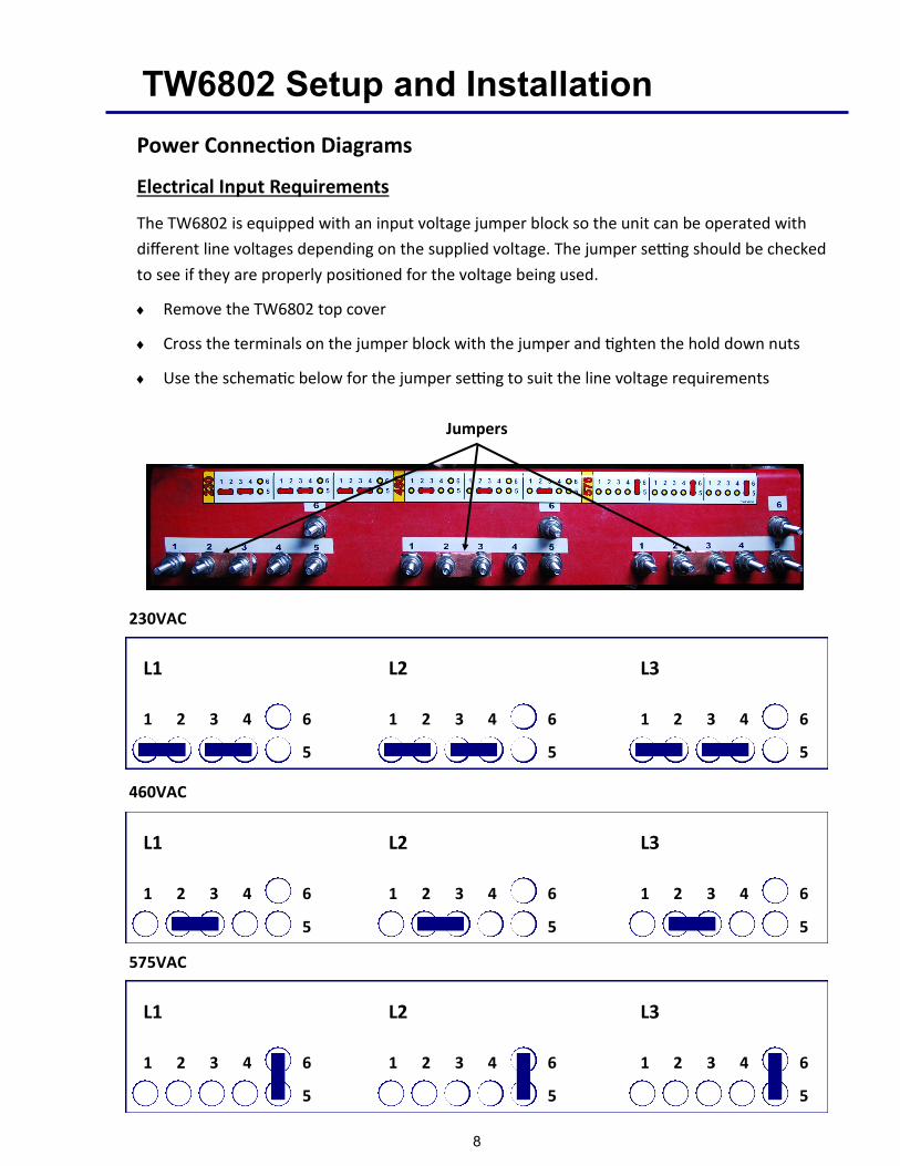
Electrical Input Requirements
The TW6802 is equipped with an input voltage jumper block so the unit can be operated with
different line voltages depending on the supplied voltage. The jumper setting should be checked
to see if they are properly positioned for the voltage being used.
Remove the TW6802 top cover
Cross the terminals on the jumper block with the jumper and tighten the hold down nuts
Use the schematic below for the jumper setting to suit the line voltage requirements
1 2 3 4
5
6 1 2 3 4
5
6 1 2 3 4
5
6
L1 L2 L3
1 2 3 4
5
6 1 2 3 4
5
6 1 2 3 4
5
6
L1 L2 L3
460VAC
Jumpers
1 2 3 4
5
6 1 2 3 4
5
6 1 2 3 4
5
6
L1 L2 L3
8
575VAC
230VAC

TW6802 Setup and Installation
Preparing the Unit for Primary Power
Only qualified personnel should perform this installation.
Turn the input power off at the disconnect switch or fuse box before working on the welder
Do not touch electrically hot parts
Primary Power Cable and Ground Connection
Remove the top cover of the TW6802
Route the primary power cable through the power inlet hole in the top left corner on the
backside of the welder with enough slack to reach the terminal block
Connect the ground wire to the frame of the welder as shown below
Connect the power leads (black, white, red) to the L1, L2, and L3 connectors on the terminal
block, as shown below
Power
Connections
Ground
Connection
9
Stud Gun Setup
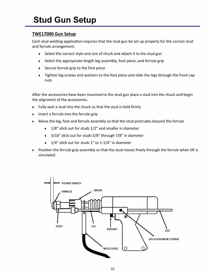
TWE17000 Gun Setup
Each stud welding application requires that the stud gun be set up properly for the correct stud and ferrule arrangement.
Select the correct style and size of chuck and attach it to the stud gun
Select the appropriate length leg assembly, foot piece, and ferrule grip
Secure ferrule grip to the foot piece
Tighten leg screws and washers to the foot piece and slide the legs through the front cap nuts
After the accessories have been mounted to the stud gun place a stud into the chuck and begin the alignment of the accessories.
Fully seat a stud into the chuck so that the stud is held firmly
Insert a ferrule into the ferrule grip
Move the leg, foot and ferrule assembly so that the stud protrudes beyond the ferrule
1/8” stick out for studs 1/2" and smaller in diameter
3/16” stick out for studs 5/8” through 7/8” in diameter
1/4” stick out for studs 1” to 1-1/4” in diameter
Position the ferrule grip assembly so that the stud moves freely through the ferrule when lift is simulated
10

Stud Gun Setup
Lift
Set the lift when all of the accessories and stud have been properly set on the stud gun and prior to welding. Plug the stud gun control connector directly into the stud welder (do not attach the weld cable). Turn on the stud welder and actuate the trigger of the stud gun with the stud and ferrule in place. Note the retraction of the shaft of the stud gun, this is designated as the lift.
The lift setting should be approximately 3/32” for general welding applications and studs ranging up to 3/4” in diameter. Larger diameter studs and select applications should have an 1/8” lift setting.
Adjusting the lift:
Remove the back cap of the stud gun
Loosen the two socket set screws around the periphery of the lift adjustment screw
To increase lift rotate the lift adjustment screw counter clockwise and to decrease lift rotate clockwise
With each turn check the lift by actuating the stud gun until the desired lift is achieved
Tighten the socket set screws to hold the lift adjustment screw in place to secure the selected setting
Replace the back cap of the stud gun
Rear coil yoke
Set screw
Lift adjusting screw
Gun body
11

Stud Gun Setup
Free Travel Adjustment
This adjustment can be used to control the force with which the stud is plunged into the molten weld pool by moving the engagement point of when the shaft of the stud gun engages the damp-ener. Rotating the dampener cover counter clockwise increases the amount of free travel.
Dampener cover
12
Attaching the stud gun to start welding
Select the gun, control cable, and weld cable that is recommended for the specific type of welder and job
Attach stud gun to weld and control cable extension
Actuate the stud gun without placing it on the surface to be welded to assure that the connection through the control cable is correct to complete the circuit
Confirm time and current settings are correct
Place the selected stud into the chuck and attach the ferrule to the ferrule grip
Place stud onto surface to be welded and press stud gun down until ferrule is flush with the welding surface
Trigger the gun and hold in place until cycle is completed
Pull gun assembly straight up off of the welded stud
Do not depress trigger when removing gun from stud
Remove the ferrule by breaking it off and inspect the weld
Make proper adjustments if needed

TW6802 Cable Connection
Ground Cable Connections
The TW6802 is equipped with two ground cable connections located beneath the access panel
on the front of the machine
Tighten the ground cable to the bracket and secure the heavy duty C-clamp to the work
surface
Access panel Ground connections
Ground cable lug
Ground cable C-clamp
13

TW6802 Cable Connection
Weld Cable Connections
The TW6802 has two weld and control cable connections on the front of the welder behind
the access panel
Tighten the weld cable lug to the weld cable bracket labeled Gun 1
Plug the male control cable connector to the female panel mount labeled Gun 1
Repeat these steps for the Gun 2 connections
Access Panel Weld Cable Connections
(Dual Gun)
Control Cable Connections
(Dual Gun)
14

TW6802 Operation
TW6802 Power Switch/Power On
The power switch for the TW6802 is located on the right
front of the welder’s control panel. Off position is verti-
cal with the “O” showing. On position is horizontal with
the “I” displayed.
When the welder is turned on, the digital display will go
through a self-diagnostic check. This takes approximately
3 to 5 seconds, and then the digital display will show the
last time and current setting. Once the time and current
is displayed, the unit is ready to weld. When connected
to the welder, the stud gun will actuate 3 times, indi-
cating that there is a good connection.
TW6802 Control Panel
Brightness Switch — LED brightness can be set to indoor or outdoor brightness levels
Time Button — Used to adjust time settings
Current Button — Used to adjust current settings
Digital Display — Displays weld settings, machine presets, or weld counters
Diagnostic LED — Used to determine an issue with weld/control cable or machine
Fine/Coarse Switch — Can be selected to adjust time or current by 10th’s or 100th’s
Menu Options — Shows which menu the machine is displaying
Adjustment Dial — Used to toggle through menus or adjust the time and current
Supervisor Lock — Locks the machine so changes cannot be made to the weld settings
Brightness Switch
Adjustment Dial Current Button
Digital Display
Time Button
Fine/Coarse Switch
Supervisor Lock
Menu Options
Diagnostic LED
15

TW6802 Operation
Menu Selection
By depressing the adjustment dial and rotating clockwise or counter clockwise a
menu can be chosen. The menus include weld settings, welding presets, job
counter, and a lifetime unit counter.
Menu Selection:
1. Verify supervisor lock is off
2. To chose a menu, depress and hold down the adjustment dial
3. Turn adjustment dial clockwise or counter-clockwise to cycle through the different menu options
4. Stop rotating the dial when the LED for the desired menu is illuminated
5. Release the adjustment dial
Adjustment dial
Supervisor lock
Menu options
16

TW6802 Operation
Weld Settings - Time and Current
The time and current controls are located on the front of the welder. The controls
consist of a time button, current button, adjustment dial, fine/coarse switch, and a
supervisor lock. The digital display will indicate the settings chosen during setup.
Adjusting the Time Setting:
1. Verify the supervisor lock is off
2. Set the FINE/COARSE switch to the desired position
3. Press and hold the TIME button
4. Turn the dial to adjust the setting
5. Release the TIME button
Adjusting the Current Setting:
1. Verify the supervisor lock is off
2. Set the FINE/COARSE switch to the desired position
3. Press and hold the AMPS button
4. Turn the dial to adjust the setting
5. Release the AMPS button
Adjustment dial
Current button
Digital display
Time button
Fine/Coarse switch
Supervisor lock
17

TW6802 Operation
Preset Menu
The full range of studs the machine is capable of welding is preloaded onto the unit for fast and easy access. Any combination of time and current can also be saved to a programmable preset location.
Selecting Custom Presets:
1. Navigate to the Preset Menu
2. Rotate the dial counter-clockwise to the desired preset
3. Press and release dial
Saving Custom Presets:
1. Set the weld settings to the settings to be saved
2. Navigate to the Preset Menu
3. Navigate to the desired custom preset
4. Press and hold the dial in until the menu switches back to the Weld Settings Menu
Selecting a Factory Preset:
1. Navigate to the Preset Menu
2. Rotate the dial clockwise to the desired stud diameter
3. Press and release the dial
Exiting back to the Weld Settings Menu (all available options):
1. Navigate to the Weld Settings Menu using the dial method listed previously
2. Turn the dial to the end of the custom preset options, press and release the dial
3. Turn the dial to the end of the factory preset options, press and release the dial
4. Press and release the AMPS or TIME adjustment buttons
18

TW6802 Operation
Weld Counter and Weld Counter Reset
The TW6802 is equipped with two different counters to display the number of times
the unit has drawn an arc.
Job Counter (Resettable) - Is a running total of the number of welds since the coun-
ter was last reset. This counter can easily be reset from the job counter menu.
Unit Weld Counter (Non-resettable) - Is a running total of every time an arc is drawn
on the machine. This is programmed from the factory and can not be reset.
Resetting The Job Counter:
1. Navigate to the Job Counter Menu
2. Press and hold the dial in until the counter changes to 0
Viewing Unit Counter:
1. Navigate to the Unit Counter Menu
Exiting Unit/Job Counter: - To exit the counter menu navigate to the weld settings
menu using the dial method or press and release the AMPS or TIME adjustment
buttons.
Job counter will display here
19

TW6802 Suggested Weld Settings
Suggested Settings (Full Base Diameter Studs)
D
IA IN
CH
TI
ME
SEC
A
MP
S D
C
DIA
DEC
D
IA M
M
1/4
0
.20
0
50
0
.25
0
6.3
5
5/1
6
0.3
00
5
50
.3
12
7
.93
3/8
0
.35
0
60
0
.37
5
9.5
2
7/1
6
0.4
20
7
00
.4
37
1
1.1
1
1/2
0
.50
0
90
0
.50
0
12
.70
5/8
0
.67
0
12
00
.6
25
1
5.8
7
3/4
0
.83
0
16
00
.7
50
1
9.0
4
7/8
1
.00
0
18
00
.8
75
2
2.2
2
1
1.2
00
2
10
0
1.0
00
2
5.4
0
1-1
/4
1.8
00
2
40
0
1.2
50
3
1.7
0
AP
PR
OX
IMA
TE
SETT
ING
S FO
R T
HR
U-D
ECK
WEL
DIN
G
3/4
.8
00
- 1
.4
16-
19
00
.7
50
1
9.0
4
7/8
1
.0 -
1.6
1
8-2
20
0
.87
5
22
.22
20
TW6802 Welding
Stud Welding - Step by Step
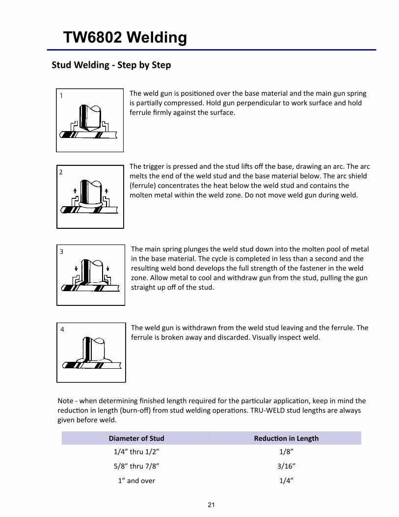
The weld gun is positioned over the base material and the main gun spring is partially compressed. Hold gun perpendicular to work surface and hold ferrule firmly against the surface.
The trigger is pressed and the stud lifts off the base, drawing an arc. The arc melts the end of the weld stud and the base material below. The arc shield (ferrule) concentrates the heat below the weld stud and contains the molten metal within the weld zone. Do not move weld gun during weld.
The main spring plunges the weld stud down into the molten pool of metal in the base material. The cycle is completed in less than a second and the resulting weld bond develops the full strength of the fastener in the weld zone. Allow metal to cool and withdraw gun from the stud, pulling the gun straight up off of the stud.
The weld gun is withdrawn from the weld stud leaving and the ferrule. The ferrule is broken away and discarded. Visually inspect weld.
Note - when determining finished length required for the particular application, keep in mind the reduction in length (burn-off) from stud welding operations. TRU-WELD stud lengths are always given before weld.
Diameter of Stud Reduction in Length
1/4” thru 1/2” 1/8”
5/8” thru 7/8” 3/16”
1” and over 1/4”
21

TW6802 Welding Hints and Suggestions
Stud Welding
• Keep weld studs and ferrules clean and dry
• Set the time for the appropriate weld base diameter (see chart on page 19)
• Set the amperage for the appropriate weld base diameter (see chart on page 19)
• Make sure the negative polarity is to the weld stud gun and ensure a good, clean ground connection
• Align accessories so they are centered and adjust legs so that 3/16” to 1/4” of the stud protrudes beyond the ferrule
• Make sure work surface is relatively clean so impurities do not affect weld
• Remove all coatings from weld areas
• Test the welds at the beginning of each shift or change in stud size. Bend two studs 30° after cooling (AWS Bend Test)
• Check burn off (1/8” – 3/16”), color (silver-blue and shiny), and weld fillet (360°).
• Visually inspect all welds
Thru-Deck Stud Welding
• Keep weld studs and ferrules clean and dry
• Never attempt thru-deck welding when the ambient temperature is below 32oF
• Deck must be layered flat on supporting members
• Deck must be properly grounded, be sure all cable connections are tight and secure
• Always use a thru-deck style ferrule
• Visually inspect all welds
To ensure satisfactory welds, bend test a minimum of one stud out of every one-hundred, by striking
stud with a hammer and bending the stud 15o from its original axis
22

TW6802 Weld Inspection
Visual Weld Inspection and Adjustments - After shooting the stud, break away ferrule and visually inspect the weld.
Good Weld
A good weld will have a smooth and even fillet with a blue-silver tint.
Partial Weld
A partial weld will result in a collar that does not extend around the entire diameter of the stud base. This outcome often occurs when the weld current is set too low.
Irregular Weld
Irregular welds normally occur when the weld time is set too high and the fillet will be bumpy or jagged in appearance.
Porous Weld Collar
A porous weld fillet forms from the oxidation of the weld pool when the weld time is set too long and/or current is set too low.
Weld Collar Off-Center
Off-center weld collars have a thick fillet on one half of the stud base and the stud may be tilted. Typically moving the or not having the gun perpen-dicular to the base material will result in an off-center collar.
23

TW6802 Troubleshooting
Problem Possible Cause Fix
Unit will not turn on No power 1. Test 3 phase power to control contactor
2. Check taps (if applicable) on main transformer
3. Check voltage selection plug near control transformer
4. Check fuse located on control transformer
5. Look for power available LED on control transformer
6. Make these checks before contacting a TWE Rep
Fan does not run when unit is
turned on
This is normal The fan will cycle on when the main bridge has reached nom-
inal operating temperature. Ambient temperature of the
weld site should also be taken in consideration.
Fan runs continuously (does
not cycle on/off)
Thermostat circuit A fault in the thermostatic circuit will cause the fan to run
continuously, call a local TRU-WELD rep. for repairs
Unit turns on, coil boot test is
good, no trigger from weld
gun
Bad connection or
faulty equipment
1. Test control cable by plugging weld tool directly into unit
(4 conductor straight through wiring)
2. Check gun trigger resistance (<100 ohms when closed)
3. Check to see if trigger LED on control panel responds
4. Check to see if weld tool is wired accordingly
5. Locate Touch/Trigger control board #16002, check and
note the operation of the driver LED’s and report the
status
Unit turns on, no coil test, no
lift from gun coil, trigger is
good
Bad connection or
faulty equipment
1. Test control cable by plugging weld tool directly into unit
(4 conductor straight through wiring)
2. Check 10 amp fuse on control board box next to breakers
3. Check hand tool coil resistance (12 - 40 ohms)
4. Locate Touch/Trigger Control Board TWE16158-1, check
and note the operation of the driver LED’s and report the
status
Gun lifts, no weld arc drawn Bad connection or
faulty equipment
1. Check connections for ground and weld tool leads
2. Check if contact LED on control panel lights when stud is
touched to work surface (closing circuit)
3. Check the two circuit breakers on the control board box
4. Check to see if you have the sustaining arc (a small blue
arc for the duration of the weld time)
5. Check to see if the stud sparks at the end of the weld
cycle (hot plunge)
6. Locate Touch/Trigger Control Board TWE16158-1, check
and note the operation of the driver LED’s and report the
status
24

TW6802 Troubleshooting
Problem Possible Cause Fix
Unit stops welding,
overtemp LED is on
Over heating 1. If the fan is running, allow unit to cool
2. Slow down welding rate (fewer studs per minute)
3. Any fault in the overtemp thermostat circuit will shut the
system down
Weld output erratic or weak Adjustments or
settings
1. Check welding hand tool set up, lift, plunge, and
accessory adjustments
2. Check ALL weld current carry leads and connections,
including grounds
3. Test the power loop by making welds on a test piece
using only the starter cable set
4. Test 3 phase power to control contactor
5. Check taps (if applicable) on main transformer
Weld gun lifts, but does not
plunge
Gun maintenance If this happens, it is most likely binding inside of the gun.
Perform routine gun maintenance or replace gun if needed
Note - Always turn off power to the welder before working on or testing components
within the welder. Contact a TRU-WELD representative for replacement parts and for
servicing welding equipment.
25
TW6802 Troubleshooting
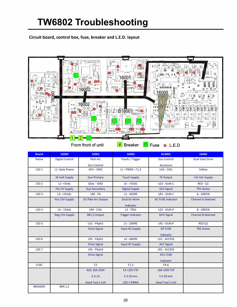
Circuit board, control box, fuse, breaker and L.E.D. layout
Board 16000 16001 16002 B16001 16060
Name Digital Control Pilot Arc
Gun Control
Touch / Trigger Gun Control
Accessory
Dual Gate Drive
LED 1 L1- Gate Power GPri - SSR1 L1 - PWRA - F1,3 LG4 - COIL Yellow
36 Volt Supply Gun Primary Touch Supply YZ Output +15 Vdc Supply
LED 2 L2- +5Vdc GSec - SSR2 L6 - +5VDC LG3 - GUN-C RED - Q1
Pos 5V Supply Gun Secondary Digital Supply GLV Signal TR1 Active
LED 3 L3- +15Vdc LR6 - PA L2 - WORK LR3 - GUN-C A - GREEN
Pos 15V Supply D1 Pilot Arc Output Stud On Work
Indicator
GC FUSE Indicator Channel A Selected
LED 4 L4- -15Vdc LR4 - COIL L3 - TRIG LG2 - GUN-P B - GREEN
Neg 15V Supply BR1,2 Output Trigger Indicator GHV Signal Channel B Selected
LED 5 LG1 - PAph2 L5 - 2WIRE LR2 - GUN-P RED Q2
Drive Signal Input #2 Supply GP FUSE
Indicator
TR2 Active
LED 6 LR5 - PAph1 L4 - 4WIRE LG1 - ACCESS
Drive Signal Input #1 Supply ACC Signal
LED 7 LR1 - PAph3 LR2 - ACCESS
Drive Signal ACC FUSE
Indicator
FUSE F2 F1,3 F4-6
AGC 10A 250V
¼ X 1¼
Hand Tool 1 Coil
1A 125V FST
5 X 20 mm
LED 1 PWRA
10A 250V FST
5 X 20 mm
Hand Tool 2 Coil
BREAKER BKR 1,2
26

TW6802 Parts and Accessories
Closed Ferrule Grips (1” Long) Brass Split Ferrule Grip (1” Long) Brass
Stud Diameter Part Number Stud Diameter Part Number
3/4” GN-075 3/4” GC-075
7/8” GN-087 7/8” GC-087
1” GN-100 1” GC-100
Adjustable Chucks Headed Chucks
Stud Diameter Part Number Stud Diameter Part Number
3/4” CN-075 5/8 & 3/4” CH-075
7/8” CN-087 7/8” CH-087
1” CN-100 1” CH-100
Gun Legs Thru-Deck Accessories
Diameter & length Part Number Description Part Number
5/16” x 7” L-03107 Thru-Deck Foot Assembly B-0021P or B-0021A
5/16” x 9” L-03109 Foot Only B-0021-1P or B-0021-1A
5/16” x 14” L-03114 Extension Bar B-0021-2
5/16” x 18” L-03118 Screws B-0021-3
3/8” x 7” L-03707 Thru-Deck Ferrule Holder Part Number
3/8” x 9” L-03709 3/4” WTD/ 7/8” Flat B-0060-1
3/8” x 14” L-03714 3/4” Flat B-0060-2
3/8” x 18” L-03718 5/8” Flat B-0060-3
3/8” x 24” L-03724 1” Flat B-0060-4
3/8” x 27” L-03727 1/2” Flat B-0060-5
3/8” x 32” L-03732 Twin Leg Ferrule Foot Plates
3/8” x 36” L-03736 Diameter Part Number
3/8” x 48” L-03748 1/4” QN-025
Gun Feet 5/16” QN-031
1/4 - 1/2” Closed B-1N 3/8” QN-037
5/8 - 3/4” Closed B-2N 1/2” QN-050
7/8 - 1” Closed B-3N 5/8” QN-062
1/4 - 1/2” Split B-1C 3/4” QN-075
5/8 - 3/4” Split B-2C 7/8” QN-087
7/8 - 1” Split B-3C 1” QN-100
27

TRU-WELD Stud Welding
Equipment Division
6400 N. Honeytown Road
Smithville, Ohio 44677
(330) 725-7744 Phone
(330) 669-2473 Fax
http://truweldstudwelding.com
Version 1 02/01/2019