Embed Size (px)
Citation preview
E.100
Stu
d t
erm
inal
s
E
Overview Stud terminals – WF / WFF
Stud terminals
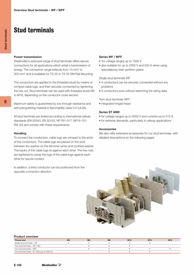
Power transmission Weidmüller’s extensive range of stud terminals offers secureconnections for all applications which entail a transmission ofenergy. The connection range extends from 10 mm2 to300 mm2 and is available for TS 35 or TS 32 DIN Rail Mounting.
The conductors are applied to the threaded studs by means ofcrimped cable lugs, and then securely connected by tighteningthe hex nut. Stud terminals can be used with threaded studs M5to M16, depending on the conductor cross-section.
Maximum safety is guaranteed by low through resistance andself-extinguishing material in flammability class V-0 (UL94). All stud terminals are tested according to international railwaystandards (EN 50343, EN 50155, NF F61-017, NF16-101;RIA 20) and comply with these requirements. HandlingTo connect the conductors, cable lugs are crimped to the endsof the conductors. The cable lugs are placed on the studbetween the washer on the terminal carrier and toothed washer.The backs of the cable lugs lie against each other. The hex nutsare tightened to press the lugs of the cable lugs against eachother for secure contact.
In addition, a third conductor can be positioned from theopposite connection direction.
Series WF / WFF• forvoltagerangesupto1000V•alsosuitableforupto2300Vand520Awhenusing
specialepoxy resin partition plates
Single stud terminals WF•4conductorscanbesecurelyconnectedwithoutany
problems•3conductorsevenwithoutrestrictingtheratingdata
Twin-stud terminals WFF•integratedhingedhead
Series ST 4000•forvoltagerangesupto4000Vandcurrentsupto415A•forextremedemands,particularlyinrailwayapplications
AccessoriesWe also offer extensive accessories for our stud terminals, withdetailed descriptions on the following pages.
Product overviewThread size M5 M6 M8 M10 M12 M16Single-stud terminals – WF • • • • •
Two-stud terminals – WF 2 BZ • • •
Two-stud terminals – WFF • • • • •Two-stud terminals – ST 4000 (up to 4000 V) • • •

E.101
Stu
d t
erm
inal
s
E
Cross connections•Fasterelectricaldistributionforclear
time savings•Canbeusedforallstudterminals•Availablein2,3and4-polesversion•Electricaldistributionpossiblebetween
different sizes (from WF6 to WF8 and to WF10)
Voltage range•WF/WFFupto2.300V•ST4000upto4.000V
StandardsFulfil requirements for standard terminalsand specific railway standards•EN60947-7-1•EN50124-1•DINEN61373•RIA20•EN50343•NFF61-017
Easy to use •Cablelugsplacedonwasheronstud•Washerandtoothedwasherplaced
on top•Steelnuttightenedtocreatecontact
between cable lugs and – if applicable – busbar
Wemid clamp support•Non-tracking,CTI600•Thermallystableupto120°C•Self-extinguishingV0flammability
class to UL94•Nohazardoussubstances•Lowsmokeandfume.•Complieswiththe
requirements of DIN 5510 part 2, railway standard NFF 16-101 and BS 6853
Safe to use Shock protection •inWFwithpartitionplatesand
transparent cover strips•inWFFwithlockingcoverforeach
connection•inST4000withscrew-on
polycarbonate cover
Reliable contact•Maintenancefree,noneedto
retighten the nuts•Toothedwasherforvibration-proof,
high strength contact•Cablelugscontact
directly or via a highly conductive busbar
Stud connection•StudsizeM5toM16•Conductorwithcablelug
to DIN 46234 up to 240 mm2 to DIN 46235 up to 300 mm2
•3cablelugspossibleperstud,even 4 cable lugs with the WF-Series
“Toothed” washer withprotective coating.
Overview Stud terminals – WF / WFF

E.102
Stu
d t
erm
inal
s
E
Overview Stud terminals – ST 4000
Electrical distribution can be realisedbetween neighbouring stud terminalseasily with 2 and 3 poles crossconnec-tions.Cross-connectionsarealso available for different thread sizesfrom M6 to M8 or M10. In the WFF twostud terminals, firstly the partition plates have to be removed between the clamped supports. The thin web of material means they can be broken out easily to fit.
Series WF and WFF
Connection
Couldn’tbeeasier:thecablelugsareplaced on the stud with the washer andtoothed washer on top. A normal openended spanner can be used to tighten the hex screw and complete installation.
Shock protection / partition plates
Shock protection in the WF-Series isprovided by partition plates WTW andtransparent cover strips ADP. The coverstrips are locked into the guides of thepartition plates and held with clips toprevent them slipping to the side. Partitionplates ensure compliance with the ratedvoltage:•Voltagerangeupto1000Vwith
partition plate WTW WF•Voltagerangeupto2300VforWFwith
epoxy partition plate WTW WF 2300
Shock protection
The two-stud terminals in the WF-Seriesoffer with an integrated hinged cover ahigh degree of finger safety. When closed,the cover locks onto the terminal andprotects the contact from accidentalcontact.
Stud terminals - Accessories
Electrical distribution

E.103
Stu
d t
erm
inal
s
E
Overview Stud terminals – ST 4000
Series ST 4000
Connection
Couldn’tbeeasier:thecablelugsareplaced on the stud with the washer andtoothed washer on top. Tighten the steelhexagonal nut to ensure good contactbetween cable lug and busbar.
The same principle applies when twocable lugs contact on one stud or slottedhole cable lugs are used.
Slotted hole cable lugs can also beplaced over both studs.
Potential distribution
When two neighbouring ST 4000terminals have the same current,cross-connectors are fitted instead ofthe busbar.
The pairs of holes in the cross-connectionare rated exactly to the spacing ofST 4000.
Here the partition plate has to be replacedbytheconnectingpieceST4000/SC130orST4000/LC160.
Cross-connectionsareavailableas2,3or4-poles.
Shock protection
Stud terminals in the ST 4000 seriesoffer an ideal cover for every version.The polycarbonate cover is placedbetween the partition plates and fastenedto the stud with the plastic-coated fixingnut.
Fixing nuts are available to fit every studsize.

E
E.104
WF series
In hazardous area applications, the installation instructions
and the rated data specifications for accessories given in the
technical appendix must be followed.
Technical dataRated data with Wemid partition wallRated voltage VRated current ARated cross-section mm²Rated impulse voltage / Pollution severity kV/-Gauge to IEC 60947-1 / UL94 Flammability classApprovalsClamped cable lugsCable lug to DIN 462342 cable lugs to DIN 46234Cable lug to DIN 46234 2 cable lugs to DIN 46234Tightening torque range
Note
Width/Length/height with TS35x7.5 mm
max. current / Flexible, max. A
Max. clamping range mm²
Version
Dark beige Wemid
Note
For detailed information on other accessories and ap-plications, refer to the „Accessories“ section
Cross-connection
2-pole
3-pole
Partition wall
Dark beige Wemid
Beige epoxy resin
End bracket
Dark beige Wemid
Hood, transparent
Hood, transparent
Holder for shrouding cover, transparent
Holder for shrouding cover, transparent
Screw thread M5
WF 5 16 mm²
13 x 67 x 5476 / 160.1...16
Type Qty Order No.
WF 5 25 1790130000
With WTW...2300 made from epoxy resin, rated current is 2300 V accor-ding to prelim. EN 50124-1
Type current Qty Order No.
WQL 2 WF5 76 A 5 1812710000
WQL 3 WF5 76 A 5 1812740000
Width
WTW WF6-WF12 2.5 mm 20 1781240000
WTW WF6 2300 2 mm 20 1781230000
WEW 35/2 8 mm 100 1061200000
ADP WF6/WF8 1 1780930000
HA ADP WF6/WF10 10 1781050000
Ordering data
WS 12/5
Marking systems (see assortment in catalogue 7)
Marking tags
IEC UL CSA1000 1000 1000
76 85 8516 AWG 10...4 AWG 10...4
8 / 3 / V-0
r # i a
0.1...16 mm²0.1...16 mm²6...10 mm² 6...10 mm²2.0...4.0 Nm
Accessories
Screw thread M6
WF 6 35 mm²
17.8 x 67 x 56125 / 352.5...35
IEC UL CSA1000 1000 1000125 115 15035 AWG 14...2 AWG 14...2
8 / 3 / V-0
r # i a
2.5...35 mm²2.5...35 mm²6...35 mm² 6...25 mm²3.0...6.0 Nm
Type Qty Order No.
WF 6 25 1780850000
With WTW...2300 made from epoxy resin, rated current is 2300 V accor-ding to prelim. EN 50124-1
Type current Qty Order No.
WQL 2 WF6 125 A 5 1780970000
WQL 3 WF6 125 A 5 1780980000
Width
WTW WF6 2 mm 20 1781220000
WTW WF6 2300 2 mm 20 1781230000
WEW 35/2 8 mm 100 1061200000
ADP WF6/WF8 1 1780930000
HA ADP WF6/WF10 10 1781050000
WS 10/6
Stu
d t
erm
inal
s
Single-stud terminals

E
E.105
Screw thread M8
WF 8 50 mm²
22.8 x 67 x 65150 / 502.5...50
IEC UL CSA1000 1000 1000150 150 20050 AWG 14...1/0 AWG 14...1/0
8 / 3 / V-0
r # i a
2.5...50 mm²2.5...50 mm²6...35 mm² 6...35 mm²6.0...12 Nm
The WQL 2, for WF 6 on WF 8, is available under order no. 1808980000.
Type Qty Order No.
WF 8 25 1780860000
With WTW...2300 made from epoxy resin, rated current is 2300 V accor-ding to prelim. EN 50124-1
Type current Qty Order No.
WQL 2 WF8 150 A 5 1780990000
WQL 3 WF8 150 A 5 1781000000
Width
WTW WF8 2 mm 20 1780900000
WTW WF8 2300 2 mm 20 1780910000
WEW 35/2 8 mm 100 1061200000
ADP WF6/WF8 1 1780930000
HA ADP WF6/WF10 10 1781050000
WS 10/6
Screw thread M10
WF 10 120 mm²
33.8 x 67 x 74269 / 1206...120
IEC UL CSA1000 1000 1000269 255 320120 AWG 10...kcmil 250AWG 10...kcmil 250
8 / 3 / V-0
r # i a
6...120 mm²6...120 mm²10...95 mm² 10...95 mm²10...20 Nm
The WQL 2, for WF 6 on WF 10, is available under order no. 180662000.
Type Qty Order No.
WF 10 20 1780870000
With WTW...2300 made from epoxy resin, rated current is 2300 V accor-ding to prelim. EN 50124-1
Type current Qty Order No.
WQL 2 WF10 269 A 5 1781010000
WQL 3 WF10 269 A 5 1781020000
Width
WTW WF10/WF12 2 mm 20 1780890000
WTW WF10/WF12 2300 2 mm 20 1780920000
WEW 35/2 8 mm 100 1061200000
ADP WF10/WF12 1 1780940000
HA ADP WF6/WF10 10 1781050000
WS 10/6
Screw thread M12
WF 12 120 mm²
33.8 x 67 x 72269 / 1206...120
IEC UL CSA1000 1000 1000269 255 320120 AWG 10...kcmil 250AWG 10...kcmil 250
8 / 3 / V-0
r # i a
6...120 mm²6...120 mm²10...95 mm² 10...95 mm²14...31 Nm
Type Qty Order No.
WF 12 20 1780880000
With WTW...2300 made from epoxy resin, rated current is 2300 V accor-ding to prelim. EN 50124-1
Type current Qty Order No.
WQL 2 WF12 269 A 5 1781030000
WQL 3 WF12 269 A 5 1781040000
Width
WTW WF10/WF12 2 mm 20 1780890000
WTW WF10/WF12 2300 2 mm 20 1780920000
WEW 35/2 8 mm 100 1061200000
ADP WF10/WF12 1 1780940000
HA ADP WF6/WF10 10 1781050000
WS 10/6
Stu
d t
erm
inal
s
Single-stud terminals

E
E.106
WF 2BZ
In hazardous area applications, the installation instructions
and the rated data specifications for accessories given in the
technical appendix must be followed.
Technical dataRated data with Wemid partition wallRated voltage VRated current ARated cross-section mm²Rated impulse voltage / Pollution severity kV/-Gauge to IEC 60947-1 / UL94 Flammability classApprovalsClamped cable lugsCable lug to DIN 462342 cable lugs to DIN 46234Cable lug to DIN 46234 2 cable lugs to DIN 46234Tightening torque range
Note
Width/Length/height with TS35x7.5 mm
max. current / Flexible, max. A/mm²
Max. clamping range mm²
Version
Dark beige Wemid
Note
For detailed information on other accessories and ap-plications, refer to the „Accessories“ section
Cross-connection
2-pole
3-pole
Partition wall
Dark beige Wemid
Beige epoxy resin
End bracket
Dark beige Wemid
Hood, transparent
Hood, transparent
Holder for shrouding cover, transparent
Holder for shrouding cover, transparent
Screw thread M6
WF 6/2BZ 35 mm²
17.8 x 67 x 56125 / 352.5...35
Type Qty Order No.
WF 6/2BZ 25 1789770000
With WTW...2300 made from epoxy resin, rated current is 2300 V, accor-ding to prelim. EN 50124-1
Type current Qty Order No.
WQL 2 WF6 125 A 5 1780970000
WQL 3 WF6 125 A 5 1780980000
Width
WTW WF10/WF12 2 mm 20 1780890000
WTW WF6 2300 2 mm 20 1781230000
WEW 35/2 8 mm 100 1061200000
ADP WF10/WF12 1 1780940000
HA ADP WF6/WF10 10 1781050000
Ordering data
WS 12/5
Marking systems (see assortment in catalogue 7)
Marking tags
IEC UL CSA1000 1000 1000125 115 15035 AWG 14...2 AWG 14...2
8 / 3 / V-0
{ #
2.5...35 mm²2.5...35 mm²6...25 mm² 6...25 mm²3.0...6.0 Nm
Accessories
Screw thread M8
WF 8/2BZ 50 mm²
22.8 x 67 x 65150 / 502.5...50
IEC UL CSA1000 1000 1000150 150 20050 AWG 14...1/0 AWG 14...1/0
8 / 3 / V-0
{ #
2.5...50 mm²2.5...50 mm²6...35 mm² 6...35 mm²6.0...12 Nm
Type Qty Order No.
WF 8/2BZ 25 1789780000
With WTW...2300 made from epoxy resin, rated current is 2300 V, accor-ding to prelim. EN 50124-1
Type current Qty Order No.
WQL 2 WF8 150 A 5 1780990000
WQL 3 WF8 150 A 5 1781000000
Width
WTW WF10/WF12 2 mm 20 1780890000
WTW WF8 2300 2 mm 20 1780910000
WEW 35/2 8 mm 100 1061200000
ADP WF10/WF12 1 1780940000
HA ADP WF6/WF10 10 1781050000
WS 12/5
Stu
d t
erm
inal
s
Twin stud terminals

E
E.107
Screw thread M10
WF 10/2BZ 120 mm²
33.8 x 67 x 74269 / 1206...120
IEC UL CSA1000 1000 1000269 230 320120 AWG 10...kcmil 250AWG 10...kcmil 250
8 / 3 / V-0
{ #
6...120 mm²6...120 mm²10...95 mm² 10...95 mm²10...20 Nm
Type Qty Order No.
WF 10/2BZ 20 1789790000
With WTW...2300 made from epoxy resin, rated current is 1500 V up to 70 mm², according to prelim. EN 50124-1
Type current Qty Order No.
WQL 2 WF10 269 A 5 1781010000
WQL 3 WF10 269 A 5 1781020000
Width
WTW WF10/WF12 2 mm 20 1780890000
WTW WF10/WF12 2300 2 mm 20 1780920000
WEW 35/2 8 mm 100 1061200000
ADP WF10/WF12 1 1780940000
HA ADP WF6/WF10 10 1781050000
WS 12/5
Stu
d t
erm
inal
s
Twin stud terminals

E
E.108
WFF series
In hazardous area applications, the installation instructions
and the rated data specifications for accessories given in the
technical appendix must be followed.
Technical dataRated data with Wemid partition wallRated voltage VRated current ARated cross-section mm²Rated impulse voltage / Pollution severity kV/-Gauge to IEC 60947-1 / UL94 Flammability classApprovalsClamped cable lugsCable lug to DIN 46234 / 2 cable lugs to DIN 46234Cable lug to DIN 46234 / 2 cable lugs to DIN 46234Tightening torque range
Note
Width/Length/height with TS35x7.5 mm
max. current / Flexible, max. A/mm²
Max. clamping range mm²
Version
Dark beige Wemid
Dark beige Wemid
Blue Wemid
Note
For detailed information on other accessories and ap-plications, refer to the „Accessories“ section
Cross-connection
2-pole
3-pole
Partition wall
Dark beige Wemid
End bracket
Dark beige Wemid
Hood
Hood, dark beige Wemid
Warning triangle for power supply terminals
Screw thread M6
WFF 35 35 mm²
27 x 107 x 54.5150 / 502.5...50
Type Qty Order No.
WFF 35 10 1028300000
WFF 35/AH 5 1029300000
WFF 35 BL 10 1028380000
WAH 35 in blue, order no. 1064480000
Type current Qty Order No.
WQL 2 WFF35 150 A 5 1064900000
WQL 3 WFF35 150 A 5 1065400000
Width
WTW WFF35 2 mm 10 1067100000
WEW 35/1 12 mm 50 1059000000
WAH 35 20 1064460000
WD 1 25 K KARTE A 6 ST 5 1563900000
Ordering data
WS 12/6,5
Marking systems (see assortment in catalogue 7)
Marking tags
IEC UL CSA EN 60079-71000 1000 600 1100125 115 130 10935 AWG 14...2 AWG 14...2 35
8 / 3 / V-0
r u # i ~ x a KEMA 98ATEX1684 U
2.5...50 mm² / 2.5...35 mm²6...25 mm² / 6...25 mm²3.0...6.0 Nm
Accessories
Ex e II T II 2 G D
75
627
Technical drawing
Screw thread M8
WFF 70 70 mm²
32 x 132 x 64232 / 952.5...95
IEC UL CSA EN 60079-71000 1000 600 1100192 175 170 16770 AWG 14...2/0 AWG 14...2/0 70
8 / 3 / V-0
r u # i ~ x a KEMA 98ATEX1684 U
2.5...95 mm² / 2.5...70 mm²16...70 mm² / 16...70 mm²6.0...12 Nm
Ex e II T II 2 G D
Type Qty Order No.
WFF 70 10 1028400000
WFF 70/AH 5 1029400000
WFF 70 BL 10 1028480000
WAH 70 in blue, order no. 1064580000
Type current Qty Order No.
WQL 2 WFF70 232 A 5 1065000000
WQL 3 WFF70 232 A 5 1065500000
Width
WTW WFF70 2 mm 10 1067200000
WEW 35/1 12 mm 50 1059000000
WAH 70 BE 20 1064560000
WD 1 25 K KARTE A 6 ST 5 1563900000
WS 12/6,5
632
100
Stu
d t
erm
inal
s
Twin stud terminals

E
E.109
Screw thread M10
WFF 120 120 mm²
42 x 132 x 73309 / 1506...150
IEC UL CSA EN 60079-71000 1000 600 1100269 310 310 234120 AWG 10...kcmil 250AWG 10...kcmil 250 120
8 / 3 / V-0
r u # i ~ x a KEMA 98ATEX1684 U
6...150 mm² / 6...120 mm²16...150 mm² / 16...120 mm²10...20 Nm
Ex e II T II 2 G D
Type Qty Order No.
WFF 120 5 1028500000
WFF 120/AH 4 1029500000
WFF 120 BL 5 1028580000
WAH 120 in blue, order no. 1064650000
Type current Qty Order No.
WQL 2 WFF120 269 A 5 1065100000
WQL 3 WFF120 269 A 5 1065600000
Width
WTW WFF120 2 mm 10 1067300000
WEW 35/1 12 mm 50 1059000000
WAH 120 20 1064660000
WD 1 25 K KARTE A 6 ST 5 1563900000
WS 12/6,5
100
16426
42
Screw thread M12
WFF 185 185 mm²
55 x 163 x 79415 / 24010...240
IEC UL CSA EN 60079-71000 1000 600 1100353 380 360 307185 AWG 8...kcmil 500 AWG 8...kcmil 500 185
8 / 3 / V-0
r u # i ~ x a KEMA 98ATEX1684 U
10...240 mm² / 10...185 mm²25...240 mm² / 25...185 mm²14...31 Nm
Ex e II T II 2 G D
Type Qty Order No.
WFF 185 4 1028600000
WFF 185/AH 2 1029600000
WFF 185 BL 4 1028680000
WAH 185/300 in blue, order no. 1064780000
Type current Qty Order No.
WQL 2 WFF185 353 A 5 1065200000
WQL 3 WFF185 353 A 5 1065700000
Width
WTW WFF185/300 2 mm 10 1067400000
WEW 35/1 12 mm 50 1059000000
WAH 185/300 BE 10 1064760000
WD 1 25 K KARTE A 6 ST 5 1563900000
WS 12/6,5
100
55
55
6
23.1
5
Screw thread M16
WFF 300 300 mm²
55 x 163 x 86520 / 24025...240
IEC UL CSA EN 60079-71000 1000 600 1100520 500 510 452300 AWG 6...kcmil 600 AWG 6...kcmil 600 300
8 / 3 / V-0
r # i ~ x a KEMA 98ATEX1684 U
25...240 mm² / 25...240 mm²50...300 mm² / 50...240 mm²25...60 Nm
Ex e II T II 2 G D
Type Qty Order No.
WFF 300 4 1028700000
WFF 300/AH 2 1029700000
WFF 300 BL 4 1028780000
WAH 185/300 in blue, order no. 1064780000
Type current Qty Order No.
WQL 2 WFF300 520 A 5 1065300000
WQL 3 WFF300 520 A 5 1065800000
Width
WTW WFF185/300 2 mm 10 1067400000
WEW 35/1 12 mm 50 1059000000
WAH 185/300 BE 10 1064760000
WD 1 25 K KARTE A 6 ST 5 1563900000
WS 12/6,5
100
55
55
6
23.1
5
Stu
d t
erm
inal
s
Twin stud terminals

E
E.110
ST 4000 (up to 4 kV)
In hazardous area applications, the installation instructions
and the rated data specifications for accessories given in the
technical appendix must be followed.
Technical dataRated data with Wemid partition wallRated voltage VRated current ARated cross-section mm²Rated impulse voltage / Pollution severity kV/-Gauge to IEC 60947-1 / UL94 Flammability classApprovalsClamped cable lugsCable lug to DIN 462342 cable lugs to DIN 46234Cable lug to DIN 46234 2 cable lugs to DIN 46234Tightening torque range
Note
Width/Length/height with TS35x7.5 mm
max. current / Flexible, max. A/mm²
Max. clamping range mm²
Version
red
With internal thread
Note
For detailed information on other accessories and ap-plications, refer to the „Accessories“ section
Cross-connection
2-pole
3-pole
4-pole
Busbar
M8 / 4 mm thick
M10 / 4 mm thick
M10 / 6 mm thick
M12 / 4 mm thick
M12 / 6 mm thick
Connecting piece
130 mm length
160 mm length
Partition wall
150 mm length
180 mm length
End partition
150 mm length
180 mm length
Touch-safe protection
150 mm length
180 mm length
Screw thread M8
ST 4000/S M8 120 mm²
40 x 150 x 84269 / 1201.5...120
Rated voltage when using cable lugs to DIN 46234
Type Qty Order No.
ST 4000/S M8 25 1809110000
ST 4000/S M8 F 25 1809120000Weidmüller can prepare drawings for a ST 4000 application to customer specification.
Type current Qty Order No.
ST 4000/S J2 M8 269 A 100 1809310000
ST 4000/S J3 M8 269 A 50 1809320000
ST 4000/S J4 M8 269 A 25 1809330000
Width
ST 4000/S CB M8/4 100 1809250000
ST 4000/S C130 50 1809230000
ST 4000/S P150 10 mm 50 1809190000
ST 4000/S E150 10 mm 50 1809210000
ST 4000/S S150 20 1809470000
Ordering data
(see assortment in catalogue 7)
IEC UL CSA4000269120
30 / 3 / V-0
#
1.5 - 120 mm²
16...70 mm²
6.0...12 Nm
Accessories
Screw thread M10
ST 4000/S M10 120 mm²
40 x 150 x 84269 / 1204...120
IEC UL CSA4000269120
30 / 3 / V-0
#
4 - 120 mm²
10...20 Nm
Rated voltage when using cable lugs to DIN 46234
Type Qty Order No.
ST 4000/S M10 25 1809130000
ST 4000/S M10 F 25 1809140000Weidmüller can prepare drawings for a ST 4000 application to customer specification.
Type current Qty Order No.
ST 4000/S J2 M10 100 1809340000
ST 4000/S J3 M10 50 1809350000
ST 4000/S J4 M10 25 1809360000
Width
ST 4000/S CB M10/4 100 1809260000
ST 4000/S CB M10/6 100 1809270000
ST 4000/S C130 50 1809230000
ST 4000/S P150 10 mm 50 1809190000
ST 4000/S E150 10 mm 50 1809210000
ST 4000/S S150 20 1809470000
Stu
d t
erm
inal
s
Twin stud terminals

E
E.111
Screw thread M10
ST 4000/L M10 150 mm²
55 x 180 x 90309 / 15010...150
IEC UL CSA4000309150
30 / 3 / V-0
#
10 - 150 mm²
25 - 150 mm²
10...20 Nm
Rated voltage when using cable lugs to DIN 46234
Type Qty Order No.
ST 4000/L M10 15 1809150000
ST 4000/L M10 F 15 1809160000Weidmüller can prepare drawings for a ST 4000 application to customer specification.
Type current Qty Order No.
ST 4000/L J2 M10 309 A 50 1809370000
ST 4000/L J3 M10 309 A 50 1809380000
ST 4000/L J4 M10 309 A 25 1809390000
Width
ST 4000/L CB M10/4 100 1809280000
ST 4000/L C160 50 1809240000
ST 4000/L P180 10 mm 50 1809200000
ST 4000/L E180 10 mm 50 1809220000
ST 4000/L S180 1 1809480000
Screw thread M12
ST 4000/L M12 240 mm²
55 x 180 x 90415 / 24010...240
IEC UL CSA4000415240
30 / 3 / V-0
#
10...240 mm²
25...240 mm²
14...31 Nm
Rated voltage when using cable lugs to DIN 46234
Type Qty Order No.
ST 4000/L M12 15 1809170000
ST 4000/L M12 F 15 1809180000Weidmüller can prepare drawings for a ST 4000 application to customer specification.
Type current Qty Order No.
ST 4000/L J2 M12 50 1809400000
ST 4000/L J3 M12 50 1809410000
ST 4000/L J4 M12 25 1809420000
Width
ST 4000/L CB M12/4 100 1809290000
ST 4000/L CB M12/6 100 1809300000
ST 4000/L C160 50 1809240000
ST 4000/L P180 10 mm 50 1809200000
ST 4000/L E180 10 mm 50 1809220000
ST 4000/L S180 1 1809480000
Stu
d t
erm
inal
s
Twin stud terminals
E.112
Term
inal
s, W
-Ser
ies
E
Accessories W-Series
Extra functions
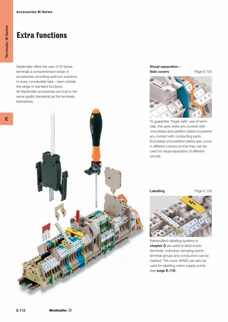
Weidmüller offers the user of W-Series terminals a comprehensive range of accessories, providing optimum solutions to every conceivable task – even outside the range of standard functions.All Weidmüller accessories are built to the same quality standards as the terminals themselves.
Visual separation –Side covers Page E.104
To guarantee “finger-safe” use of termi-nals, the open sides are covered with end plates and partition plates to prevent any contact with conducting parts. End plates and partition plates also come in different colours so that they can be used for visual separation of different circuits.
Labelling Page E.126
Weidmüller’s labelling systems in chapter G are used to label screw terminals. Individual clamping points, terminal groups and conductors can be marked. The cover (WAD) can also be used for labelling mains supply points (see page E.116).

E.113
Term
inal
s, W
-Ser
ies
E
Accessories W-Series
Fastening Page G.29
Connecting Chapter G Testing Page E.123
Specific functions / colour variations Page E.127
Power supply Page E.110 Current distribution Page E.114
An end bracket is fitted on the terminal rail to the right and left of the terminals to ensure that they sit firmly in position.The marking surface of the end bracket can also be used for group marking. Details of the wide range of Weidmüller end brackets and mounting rails are given in Chapter F.
Conductors are connected into Weidmüller terminals using standard screwdrivers, as shown in chapter F, page G.74.
The slot-in test adapter (WTA) is used as both a single unit and a test adapter strip for measurement in control cabinets. The test adapter is ideal for convenient, rational testing of assembled terminals. However, tests with socket and test plug are also always possible (page E.113).
Further helpful accessories are available for terminals using screw clamp techno-logy, such as: • Pluggablefuseholder
(SIHA 1 and SIHA 2) • Screenplug(LS),short-cir.plug(WDS)• Extensionconnectors(WZAD)• PENbridges• Accessoriesfordisconnecttest-
terminals • Terminalsinvariouscolours• Pre-fittedterminal blocks
For the W-Series, power is supplied via standard terminals in conjunction with a special cross-connection, which directly connects terminals for larger and smaller cross-sections (the picture shows WDU 35 on WDU 4). It is possible to form a link to screw-in cross-connections of smaller cross-sections(WQV2.5/4/6).Thisextendscurrent distribution to any number of other terminals of the smaller cross-section.
A screw-in and a plug-in cross-connection system is available for Weidmüller screw terminals. The plug-incross-connection (ZQV) for screw terminals is unique. It enables consider-able reductions in assembly times. The plug-in cross-connections can be used for nearly all W-Series terminals in the cross-section ranges 2.5 and 4 mm2.

E
E.114
End plates
Touch protection With only a few exceptions, the last terminal in a terminal strip must be closed off with a WAP/AP-type end plate. End plates must also be used within a terminal strip when it makes use of terminals of different sizes. This ensures the touch-safe re-quirement is met for live voltage components. The terminals are touch-safe (DIN VDE 0106-100). Optical separation Coloured end plates are very frequently used for distinguishing the circuits visually. Ensuring the operating voltage End plates can also be used to maintain the required clearance and creepage distances, in order to guarantee the rated voltage for the application. They can be used when cross-connections are used side-by-side. Contour matching The overall dimensions of the end plates match the external dimensions of the associated terminal. Mounting The end plate‘s snap-in pegs allow it to be simply fitted on to the corresponding terminal. The corresponding indentations in the terminal are used to ensure that position follows the identical contours. All colour variations are classified according to UL 94 V-0.
Term
inal
s, W
-Ser
ies
Accessories - Optical separation / lateral cover
Ordering data
Type Colour Qty Order No. For terminal:Width
WAP 2.5-10 dark beige 50 1050000000
WAP 2.5-10 BL blue/light blue 50 1050080000
WAP 2.5-10 BR brown 50 1050070000
WAP 2.5-10 GE yellow 50 1050020000
WAP 2.5-10 GE yellow 50 2068740000
WAP 2.5-10 GN green 50 1072200000
WAP 2.5-10 GR grey 50 1050050000
WAP 2.5-10 GR 7042 grey 50 1879290000
WAP 2.5-10 OR Orange 50 1050060000
WAP 2.5-10 RT red 50 1050040000
WAP 2.5-10 SW black 50 1050010000
WAP 2.5-10 VI violet 50 1072210000
WAP 2.5-10 WS white 50 1050090000
WDU 1.5/ZZ
WDU 1.5/ZZ BL
WDU 10
WDU 10 BL
WDU 10 SL
WDU 10 SL/EN
WDU 10 SL/EN SW
WDU 2.5
WDU 2.5 BL
WDU 2.5 F 2X2.8
WDU 2.5 FF 2*2.8
WDU 2.5/1.5/ZR
WDU 2.5/1.5/ZR BL
WDU 2.5/TC TYP B
WDU 2.5/TC TYP E
WDU 2.5/TC TYP J
WDU 2.5/TC TYP K
WDU 2.5/TC TYP N
WDU 2.5/TC TYP SR
WDU 2.5/TC TYP T
WDU 4
WDU 4 BL
WDU 4 SL
WDU 4 SL/EN
WDU 4 SL/EN SW
WDU 6
WDU 6 BL
WDU 6 SL
WDU 6 SL/EN
WDU 6 SL/EN SW
WDUL 4 100R/0.75W POTI
WDUL 4 10K/0,75W POTI
WDUL 4 10R/0,75W POTI
WDUL 4 1K/0,75W POTI
WDUL 4 500K/0,1W POTI
WDUL 4 500R/0,75W POTI
WDUL 4 50K/0,75W POTI
WDUL 4 5K/0,75W
WDUL 4 OHNE POTI
WNT 10 10X3
WNT 10 10X3 BE
WNT 2.5 10X3
WNT 2.5 10X3 BE
WNT 4 10X3
WNT 4 10X3 BE
WNT 6 10X3
WNT 6 10X3 BE
WPE 1.5/ZZ
WPE 10
WPE 2.5

E
E.115
Ordering data
Type Colour Qty Order No. For terminal:Width
WAP 16+35 WTW 2.5-10 dark beige 20 1050100000
WAP 16+35 WTW 2.5-10 BL blue/light blue 20 1050180000
WAP 16+35 WTW 2.5-10 GR grey 20 1879140000
WAP 16+35 WTW 2.5-10 OR Orange 20 1050160000
WDK 2.5 / 800V
WDK 2.5 FF
WDU 1.5/ZZ
WDU 1.5/ZZ BL
WDU 10
WDU 10 BL
WDU 10 SL
WDU 10 SL/EN
WDU 10 SL/EN SW
WDU 10/ZR
WDU 10/ZR BL
WDU 16/ZA
WDU 16/ZA BL
WDU 2.5
WDU 2.5 BL
WDU 2.5 F 2X2.8
WDU 2.5 FF 2*2.8
WDU 2.5/1.5/ZR
WDU 2.5/1.5/ZR BL
WDU 2.5/TC TYP B
WDU 2.5/TC TYP E
WDU 2.5/TC TYP J
WDU 2.5/TC TYP K
WDU 2.5/TC TYP N
WDU 2.5/TC TYP SR
WDU 2.5/TC TYP T
WDU 2.5N/600 UL
WDU 35/IK/ZA
WDU 4
WDU 4 BL
WDU 4 SL
WDU 4 SL/EN
WDU 4 SL/EN SW
WDU 6
WDU 6 BL
WDU 6 SL
WDU 6 SL/EN
WDU 6 SL/EN SW
WDUL 4 100R/0.75W POTI
WDUL 4 10K/0,75W POTI
WDUL 4 10R/0,75W POTI
WDUL 4 1K/0,75W POTI
WDUL 4 500K/0,1W POTI
WDUL 4 500R/0,75W POTI
WDUL 4 50K/0,75W POTI
WDUL 4 5K/0,75W
WDUL 4 OHNE POTI
WPE 1.5/ZZ
WPE 10
WSI 6
Width
WAP WDK2.5 dark beige 20 1059100000
WAP WDK2.5 RS-SET dark beige 10 1819170000
WAP WDK2.5 BL blue/light blue 20 1059180000
WAP WDK2.5 GN green 20 1059140000
WDK 2.5
WDK 2.5 DU-PE
WDK 2.5 F
WDK 2.5 F BL
WDK 2.5 FF
WDK 2.5 FV
WDK 2.5 LD GR 1R 24VDC
WDK 2.5 LD GR 1R 24VDC
WDK 2.5 LD ROT 1R 24VDC
WDK 2.5 LD ROT 1R 24VDC
WDK 2.5 PE
WDK 2.5 / 800V
WDK 2.5 ZQV
WDK 2.5 ZQV BL
WDK 2.5/D
WDK 2.5V
WDK 2.5V BL
WDK 2.5 1D A.1
WDK 2.5 1D A.2
WDK 2.5 2D
WDK 2.5 2D
WDK 2.5 2D
WDK 2.5 BL
WDK 2.5 D
Term
inal
s, W
-Ser
ies
Accessories - Optical separation / lateral cover
Ordering data
Type Colour Qty Order No. For terminal:Width
WAP WTR2.5/ZZ dark beige 20 1074600000
WAP WTR2.5/ZZ BL blue/light blue 20 1074680000
WTR 2.5/ZZ
WTR 2.5/ZZ BL
Width
WAP WDU/WTR4/ZR dark beige 50 1905070000
WAP WDU/WTR4/ZZ dark beige 50 1905150000
WDU 4/ZR
WDU 4/ZZ
WPE 4/ZR
WPE 4/ZZ
WTR 4/ZR
WTR 4/ZR STB
WTR 4/ZZ
WTR 4/ZZ STB
Width
WAP WDL2.5/S dark beige 20 1067700000
WAP WDL2.5/S RS-SET dark beige 5 1819210000
WDL 2.5/S/L
WDL 2.5/S/L/L
WDL 2.5/S/L/L/PE
WDL 2.5/S/N/L/PE
WDL 2.5/S/NT/L/PE
Width
WAP WDL2.5 beige 20 1067800000 WDL 2.5/L
WDL 2.5/L/L
WDL 2.5/L/L/PE
WDL 2.5/N/L/PE
WDL 2.5/NT/L/PE
Width
WAP WDU1.5/BLZ dark beige 50 1577330000
WAP WDU1.5/BLZ/ZA dark beige 50 1577320000
WDU 1.5/BLZ 5.08
WDU 1.5/ZQV/BLZ 5.08
WDU 2.5/BLZ/7.62
Width
WAP WDK2.5/BLZ/M.ZA blue 20 1070100000
WAP WDK2.5/BLZ/O.ZA dark beige 20 1070000000
WDK 2.5 BLZ/5.08/ZA
WDK 2.5 BLZ/7.62/ZA
Width
AP DLI2.5 beige 20 1313260000
AP DLI2.5 DB dark beige 20 1783550000
DLA 2.5 DB
DLA 2.5/D DB
DLA 2.5/LD-GN/D DB
DLA 2.5/LD-RT DB
DLI 2,5 DB
DLI 2.5/LD-GN/NPN -+ DB
DLI 2.5/LD-GN/PNP +- DB
DLI 2.5/LD-RT/NPN -+ DB
DLI 2.5/LD-RT/PNP +- DB
Width
AP DLD2.5 DB dark beige 20 1784210000
AP DLD2.5/PE DB dark beige 20 1783800000
DLD 2.5 DB
DLD 2.5/PE DB
Width
WAP WTL6/1 dark beige 20 1068300000 WTD 6/1 EN
WTL 6/1 EN
WTL 6/1 EN STB
WTL 6/1/STB/TNSC/EN
WTQ 6/1 EN
WTQ 6/1 EN STB
Width
ZAP/TW 1 dark beige 50 1608740000
ZAP/TW 1 BL blue/light blue 50 1608750000
ZAP/TW 1 GN green 50 1683680000
ZAP/TW 1 GR grey 50 1683710000
ZAP/TW 1 OR Orange 50 1608760000
ZAP/TW 1 RT red 50 1683660000
WTL 4
WTL 4/STB
Width
WAP WDU1.5/R3.5 beige 20 1754190000 WDK 1.5/R3.5
WDK 1.5/R3.5 BL
WDU 1.5/R3.5
WDU 1.5/R3.5 BL
WPE 1.5/R3.5
Width
WAP WDK1.5/R3.5 dark beige 20 1754200000 WDK 1.5/R3.5
WDK 1.5/R3.5 BL
Width
AP AKZ1.5 beige 50 0340560000
AP AKZ1.5 BL blue 50 0340580000
AKZ 1.5
AKZ 1.5 BL
Width
AP AKZ2.5 beige 50 0697360000
AP AKZ2.5 BL blue 50 0697380000
AP AKZ2.5K beige 50 0697260000
AKZ 2.5
AKZ 2.5 BL

E
E.116
Ordering data
Type Colour Qty Order No. For terminal:Width
ADL beige 2 0210800000
AP AKZ4 DB beige 20 9537910000
AP 100 GR grey 20 1773410000
AP AKZ4 beige 20 0294460000
AP AKZ4 BL blue 20 0294480000
AP AKZ4 KRG dark beige/yellow 20 0294420000
AP AKZ4 KRS anthracite 20 0294430000
AKZ 4
AKZ 4 BL
Width
WAP WDU2.5N/4N dark beige 50 1060000000
WAP WDU2.5N/4N RS-SET dark beige 5 1819180000
WAP WDU2.5N/4N BL blue/light blue 50 1060080000
WAP WDU2.5N/4N GE yellow 50 1060090000
WAP WDU2.5N/4N OR Orange 50 1060060000
WDU 2.5N
WDU 2.5N BL
WDU 2.5N ZQV
WDU 2.5N ZQV BL
WDU 4N
WDU 4N BL
WPE 2.5N
WPE 4N
Width
WAP WDK2.5/4 N dark beige 20 1084000000
WAP WDK2.5/4 N BL Orange 20 1084080000
WAP WDK2.5/4 N GR 7042 grey 20 1859010000
WDK 2.5N
WDK 4N V
WDK 2.5N DU-PE
WDK 2.5N PE
WDK 2.5N V
WDK 2.5N/BL
WDK 4N
WDK 4N BL
WDK 4N DU-PE
WDK 4N PE
Width
WAP WTL6/3 beige 20 1879910000 WTL 6/3
Width
WAP WTL 6 SL beige 20 9538110000 WTD 6 SL
WTD 6 SL/EN
WTL 6 SL
WTL 6 SL/EN
WTL 6 SL/EN SW
Width
WAP WTL4/2 beige 50 1881640000 WTL 4/2/STB
Width
WAP WTL6/4FF beige 20 1887240000
Width
WAP WSI4/2 beige 50 1880450000 WSI 4
WSI 4/LD 60-150V AC/DC
WSI 4/2
WSI 4/2/LD 10-36V AC/DC
WSI 4/2/LD 140-250V AC/DC
WSI 4/2/LD 30-70V AC/DC
WSI 4/2/LD 60-150V AC/DC
WSI 4/LD 10-36V AC/DC
WSI 4/LD 140-250V AC/DC
WSI 4/LD 30-70V AC/DC
Width
AP VLI1.5 DB dark beige 20 1784150000
AP VLI1.5/PE DB dark beige 20 1784160000
VLI 1.5
VLI 1.5 DB
VLI 1.5/PE
VLI 1.5/PE DB
Width
AP MAK2.5 DB dark beige 20 7917000000 MAK 2.5
MAK 2.5 DB
Width
WAP WFF120 dark beige 20 1073000000
WAP WFF35 dark beige 20 1069700000
WAP WFF70 dark beige 20 1069800000
WFF 120
WFF 70/AH
WFF 120 BL
WFF 120/3/B
WFF 120/AH
WFF 35
WFF 35 BL
WFF 35/AH
WFF 70
WFF 70 BL
Term
inal
s, W
-Ser
ies
Accessories - Optical separation / lateral cover
WTL 6/4FF

E
E.117
Partition walls
Ensuring the operating voltage The main function of the partitions is to maintain the clearance and creepage distances, as required by the operating voltage. This includes applications with higher security levels (ATEX) or neighbouring groups of cross-connections. For this reason, the partitions are significantly larger than the corresponding termi-nals. Optical separation The partitions can be used to achieve a very clear separation of circuits on one terminal strip. Dimensions WAP 16+35 WTW 2.5-10 Length: 60 mm Height with TS 35 x 7.5: 63 mm WTW EN Length: 86 mm Height with TS 35 x 7.5: 63 mm
Ordering data
Type Colour Qty Order No. For terminal:Width
WAP 16+35 WTW 2.5-10 dark beige 20 1050100000
WAP 16+35 WTW 2.5-10 BL blue/light blue 20 1050180000
WAP 16+35 WTW 2.5-10 GR grey 20 1879140000
WAP 16+35 WTW 2.5-10 OR Orange 20 1050160000
WDK 2.5 / 800V
WDK 2.5 FF
WDU 1.5/ZZ
WDU 1.5/ZZ BL
WDU 10
WDU 10 BL
WDU 10 SL
WDU 10 SL/EN
WDU 10 SL/EN SW
WDU 10/ZR
WDU 10/ZR BL
WDU 16/ZA
WDU 16/ZA BL
WDU 2.5
WDU 2.5 BL
WDU 2.5 F 2X2.8
WDU 2.5 FF 2*2.8
WDU 2.5/1.5/ZR
WDU 2.5/1.5/ZR BL
WDU 2.5/TC TYP B
WDU 2.5/TC TYP E
WDU 2.5/TC TYP J
WDU 2.5/TC TYP K
WDU 2.5/TC TYP N
WDU 2.5/TC TYP SR
WDU 2.5/TC TYP T
WDU 2.5N/600 UL
WDU 35/IK/ZA
WDU 4
WDU 4 BL
WDU 4 SL
WDU 4 SL/EN
WDU 4 SL/EN SW
WDU 6
WDU 6 BL
WDU 6 SL
WDU 6 SL/EN
WDU 6 SL/EN SW
WDUL 4 100R/0.75W POTI
WDUL 4 10K/0,75W POTI
WDUL 4 10R/0,75W POTI
WDUL 4 1K/0,75W POTI
WDUL 4 500K/0,1W POTI
WDUL 4 500R/0,75W POTI
WDUL 4 50K/0,75W POTI
WDUL 4 5K/0,75W
WDUL 4 OHNE POTI
WPE 1.5/ZZ
WPE 10
WSI 6
Width
WTW EN dark beige 20 1058800000 SAKS 2/35 DB
WDK 2.5N DU-PE
WDK 2.5N PE
WDK 2.5N V
WDK 2.5N/BL
WDK 2.5V
WDK 2.5V BL
WDK 4N PE
WDU 16N
WDU 16N BL
WDU 35N
SAKS 4/35 DB
WDU 35N BL
WTD 6 SL
WTD 6 SL/EN
WTL 6 SL
WTL 6 SL/EN
WTL 6 SL/EN SW
SAKS 5/35 DB
WDK 2.5
WDK 2.5 BL
WDK 2.5 DU-PE
WDK 2.5 ZQV
WDK 2.5 ZQV BL
WDK 2.5N
Term
inal
s, W
-Ser
ies
Accessories - Optical separation / lateral cover

E.118
Term
inal
s, W
-Ser
ies
E
Accessories – Cover strips and retaining plates
Material: unplasticised PVC
Supplied in 1 m lengths
Temperature limit: max. 70 °C
transparent
Type Order No.
ADP 1 0485200000
ADP 2 0485300000
ADP 3 0485400000
grey
Type Order No.
ADP 4
(1000 mm)
1430760000
ADP 4
(300 mm)
1378160000
TSK 31.5 0347960000
Several German safety regulations, e.g. VBG 4 and VDE 0106 part 100, call for the active parts of electrical equipment to be protected against direct contact.For this purpose, Weidmüller can supply cover strips and associated retaining plates which can be used for the common sizes of terminal.Retaining plates are fitted at the ends of a terminal strip but can also be inserted between terminals. They are suitable for mounting on TS 32, TS 35 or TS 15 terminal rails.Spacing of retaining plates:The distance between the retaining plates for the ADP 1, 2 and 3 cover strips should not exceed about 300 mm.The cover strip is clipped into lugs at the sides, but can also be fixed to spigots on the retaining plates which can be provided with a lead seal.The cover strips are transparent so that terminals with accessories and markings can be identified at any time. Additional markings, e.g. groups, can be attached to the cover strips.
ADP
Cover strips
Material: PA 66
Thickness: 2 mm
For mounting on TS 35 / TS 32, with spigot for lead seal
Type Order No.
HP 1 Spigot for lead seal 0485560000
HP 2 0485660000
HP 3 0485760000
HP 4 0485860000
For mounting on TS 15
Type Order No.
HP 7 0258260000
HP 8 0258360000
HP
Retaining plates
CoversOverall dimensions A A A A B Cfor mounting on terminal rails TS 32 TS 35 x 7.5 TS 35 x 15 TS 15
ADP 1, HP 1 61 56 63 49 6
ADP 2, HP 2 77 72 79 62.5 6
ADP 3, HP 3 94 89 86 92 6
ADP 3, HP 4 73.5 68.5 75.5 92 6
ADP 1, HP 8 45 49 6
TSK 31.5, HP 7 35 31 6
Marking materials Qty. Order No.
Card with warning “lightning flash”, self adhesive
20 pcs. per card
5 0566700000

E.119
Term
inal
s, W
-Ser
ies
E

E.120
Term
inal
s, W
-Ser
ies
E
Accessories – Potential supply
Potential supply with cross-section reduction
Feed-through terminals such as WDU 35 or WDU 16 are responsible for power supply in the W-Series. The current is routed by the cross-connections shown to terminals of a smaller cross-section (cross-section reduction).After cross-section reduction, the supply can then be distributed on to any number of terminals of this same cross-section, using standard cross-connectors.
Function• Largerconductorcross-sectioncan be used for power supply
•Centralcurrentsupplyanddistri- bution to any number of circuits
Mounting
First, prepare the standard cross-connection that is to distribute the cur-rent to other terminals of smaller conduc-tor cross-section. To do so, break off the plastic screwdriver guide at the first pole of the cross-connection by bending it back and forth at the intended break-off point, and remove the fixing screw. Then place the cross-connection in the middle of the terminal.
Now insert the cross-connection for cross-section reduction so that there is an overlap of the live parts of the first ter-minal of the smaller cross-section. Fasten with the screws in the cross-section re-duction.
Important! The“QL”cross-sectionreductions are not finger-safe. This can be easily remedied by using the WAD covers for the corresponding terminals.

E.121
Term
inal
s, W
-Ser
ies
E
Accessories – Potential supply
Potential supply with cross-section reduction
Power supply via Output terminal
Technical data
Continuous current 2-pole A
Thread size
Tightening torque Nm
Ordering data
2-pole
Power supply via Output terminal
Technical data
Continuous current 2-pole A
Thread size
Tightening torque Nm
Ordering data
2-pole
Power supply via Output terminal
Technical data
Continuous current 2-pole A
Thread size
Tightening torque Nm
Ordering data
2-pole
WDU 35WDU 2.5
to WDU 35 to WDU 2.541
M 4 M 2.5
1.2 ... 1.8 0.4 ... 0.7
Type Qty. Order No.WQV 35-2.5 10 1064100000
WDU 10WDU 2.5
to WDU 10 to WDU 2.524
M 3 M 2.5
0.5 ... 0.8 0.4 ... 0.7
Type Qty. Order No.QL 10-2.5 10 1859620000
not finger-safe
WDU 35WDU 4 / WDU 6
to WDU 35 to WDU 4 / 641
M 4 M 3
1.2 ... 1.8 0.5 ... 0.8
Type Qty. Order No.WQV 35-4/6 10 1064200000
WDU 16WDU 2.5
to WDU 16 to WDU 2.541
M 4 M 2.5
1.2 ... 1.8 0.4 ... 0.7
Type Qty. Order No.WQV 16-2.5 10 1063900000
WDU 10WDU 4
to WDU 10 to WDU 432
M 3 M 3
0.5 ... 0.8 0.5 ... 0.8
Type Qty. Order No.QL 10-4 10 1859610000
not finger-safe
WDU 35WDU 10
to WDU 35 to WDU 1057
M 4 M 3
1.2 ... 1.8 0.5 ... 0.8
Type Qty. Order No.WQV 35-10 10 1068000000
WDU 16WDU 4 / WDU 6
to WDU 16 to WDU 4 / 641
M 4 M 3
1.2 ... 1.8 0.5 ... 0.8
Type Qty. Order No.WQV 16-4/6 10 1064000000

E.122
Term
inal
s, W
-Ser
ies
E
Accessories – Potential supply
Potential supply with cross-section reduction
Power supply via Output terminal
Technical data
Continuous current 2-pole A
Thread size
Tightening torque Nm
Ordering data
2-pole
WDU 16NWDU 2.5
to WDU 16 to WDU 2.524
M 3 M 2.5
0.5 ... 0.8 0.4 ... 0.7
Type Qty. Order No.WQV 16N-2.5 10 1073100000
WDU 16NWDU 4 / WDU 6
to WDU 16N to WDU 4 / 641
M 3 M 3
0.5 ... 0.8 0.5 ... 0.8
Type Qty. Order No.WQV 16N-4/6 10 1072500000
WDU 6WDU 2.5
to WDU 6 to WDU 2.524
M 3 M 2.5
0.5 ... 0.8 0.4 ... 0.7
Type Qty. Order No.QL 6-2,5 10 1859600000
not finger-safe

E.123
Term
inal
s, W
-Ser
ies
E
E.124
Term
inal
s, W
-Ser
ies
E
Accessories – Potential distribution
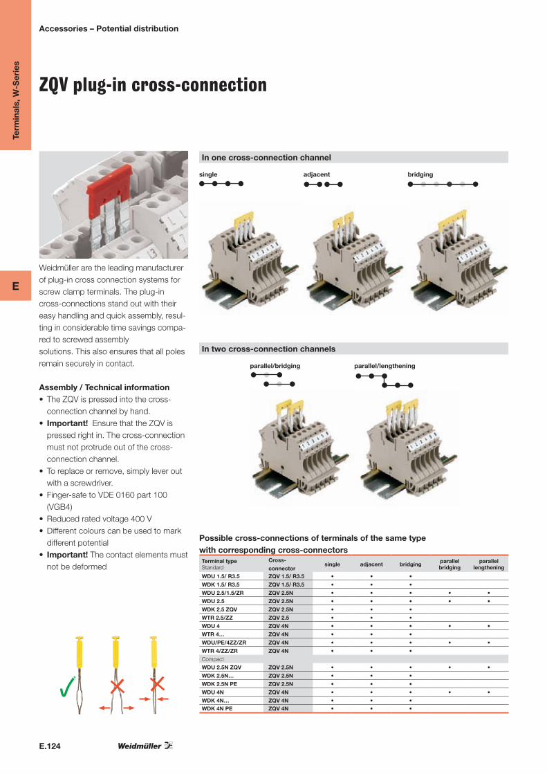
In one cross-connection channel
In two cross-connection channels
bridging
parallel/bridging
adjacent
parallel/lengthening
single
Possible cross-connections of terminals of the same type with corresponding cross-connectorsTerminal typeStandard
Cross-
connectorsingle adjacent bridging parallel
bridgingparallel
lengthening
WDU 1.5/ R3.5 ZQV 1.5/ R3.5 • • •
WDK 1.5/ R3.5 ZQV 1.5/ R3.5 • • •
WDU 2.5/1.5/ZR ZQV 2.5N • • • • •
WDU 2.5 ZQV 2.5N • • • • •
WDK 2.5 ZQV ZQV 2.5N • • •
WTR 2.5/ZZ ZQV 2.5 • • •
WDU 4 ZQV 4N • • • • •
WTR 4… ZQV 4N • • •
WDU/PE/4ZZ/ZR ZQV 4N • • • • •
WTR 4/ZZ/ZR ZQV 4N • • •
Compact
WDU 2.5N ZQV ZQV 2.5N • • • • •
WDK 2.5N… ZQV 2.5N • • •
WDK 2.5N PE ZQV 2.5N • • •
WDU 4N ZQV 4N • • • • •
WDK 4N… ZQV 4N • • •WDK 4N PE ZQV 4N • • •
ZQV plug-in cross-connection
Weidmüller are the leading manufacturer of plug-in cross connection systems for screw clamp terminals. The plug-in cross-connections stand out with their easy handling and quick assembly, resul-ting in considerable time savings compa-red to screwed assembly solutions. This also ensures that all poles remain securely in contact.
Assembly / Technical information • TheZQVispressedintothecross
connection channel by hand. • Important!EnsurethattheZQVis
pressed right in. The cross-connection must not protrude out of the cross-connection channel.
• Toreplaceorremove,simplyleveroutwith a screwdriver.
• FingersafetoVDE0160part100(VGB4)
• Reducedratedvoltage400V• Differentcolourscanbeusedtomark
different potential • Important! The contact elements must
not be deformed

E.125
Term
inal
s, W
-Ser
ies
E
Accessories – Potential distribution
No. of poles
Type I[A]
Qty. Order No.
yellow
Order No.
red
Order No.
blue
Order No.
black2 ZQV2.5N/2 24 60 1693800000 1717900000 1717990000 1718080000
3 ZQV2.5N/3 24 60 1693810000 1717910000 1718000000 1718090000
4 ZQV2.5N/4 24 60 1693820000 1717920000 1718010000 1718100000
5 ZQV2.5N/5 24 20 1693830000 1717930000 1718020000 1718110000
6 ZQV2.5N/6 24 20 1693840000 1717940000 1718030000 1718120000
7 ZQV2.5N/7 24 20 1693850000 1717950000 1718040000 1718130000
8 ZQV2.5N/8 24 20 1693860000 1717960000 1718050000 1718140000
9 ZQV2.5N/9 24 20 1693870000 1717970000 1718060000 1718150000
10 ZQV2.5N/10 24 20 1693880000 1717980000 1718070000 1718160000
20 ZQV2.5N/20 24 20 1909000000 1909110000 1909140000 1909130000For standard
terminal For compact terminalWDU2.5/1.5ZR WDU2.5N
WDU2.5 WDK2.5N
WDK2.5/ZQV WDK2.5NV
WDU1.5BLZ5.08/ZQV WDK2.5NDUPE
ZQV 2.5N
Continuous cross-connection ZQV2.5N/20(20pole)andZQV4N/20(20pole)areidealforshortening(e.g.withtoolKTZQV–9002170000)toproducecustomisedcon-figurations with the required number of poles. Morethan20polesinarowarenotrecommen-ded because of the resulting tolerances in the terminals.
Special features of WDU 2.5, WDU 4 and WDU 2.5/1.5/ZR• Paralleldistributionof3potentials
Important!Ratedvoltagereducedto125V!• Paralleldistributionof2potentials
Important! Only when using the outer crossconnectionholesat400V
• ThemiddlecrossconnectionholecanbeusedforeitherZQVorWQV
Important!ForshortenedZQVlocatedadjacenttoeachother(withbarecutedges),endplatesorpartition plates are necessary for rated voltage of 250V.
No. of poles
Type I[A]
Qty. Order No.
yellow
Order No.
red
Order No.
blue
Order No.
black2 ZQV4N/2 32 60 1758250000 1793950000 1793960000 1793970000
3 ZQV4N/3 32 60 1762630000 1793980000 1793990000 1794000000
4 ZQV4N/4 32 60 1762620000 1794010000 1794020000 1794030000
5
6
7
8
9
10 ZQV4N/10 32 20 1758260000 1794040000 1794050000 1794060000
20 ZQV4N/20 32 20 1909020000 1909150000 1909100000 1909120000For standard
terminal For compact terminalWDU4 WDU4N
WTR4 WDK4N
WTR4SI WDK4NV
WTR4SL WDK4NDUPE
WTR4/ZZ+ZR WDK2.5NV
WDU/PE4/ZZ+ZR WDK2.5NDUPE
ZQV 4N

E.126
Term
inal
s, W
-Ser
ies
E
WQV screw-in cross-connection
When used together with W-Series termi-nals,WQVinsulatedcrossconnectionunits guarantee absolute safety for finger and back-hand in accordance with the accident prevention regulation “Electrical systemsandequipment”(VGB4).Itisvery easy to produce individual configura-tions thanks to the many different options offeredbytheWQVcrossconnectionsystem, by breaking out individual segments, creating any required number of poles or routing two potentials in parallel, etc.
Technical instructions• Thefullratedcurrentoftheterminals
can be routed across any number of poles
• Noendplatesorpartitionplates neededforadjacentWQVupto400V.
Assembly• PlacetheWQVinthecrossconnection
channel in the middle of the terminal and screw tight.
• IndividualWQVsegmentscanbebro-ken out by bending over or using the WAW1tool(9004500000).Itisthenpossible to bridge individual or several terminals.
•Captivefixingscrews.• Snapontotheclampedsupport–
simple overhead assembly.
Any number of poles (extending)Prefittedcrossconnectionscanbesetone after the other to produce any required number of poles. To do so, arrange the last and first contactpointsoftwoidenticalWQVssothat they overlap.
• First,removethefixingscrewandscrewdriverguide(insulatedpart)atone of the outer contact points of one oftheWQVs.
• TheninserttheWQVwithoutfixingscrew and insulated part. At the same time,insertanunmodifiedWQVin parallel so as to produce an overlap at the connection. The connection is screwedtightusingthefixingscrewoftheunmodifiedWQV.
Routing 2 potentials in parallel • Inspiteofonlyhaving1channel,theWQVcrossconnectionsystemcanstillbe used for offset cross-connections. See the photo “parallel bridging” (pageE.107).
WQV in combination with a socket contact and test plug • RemovethefixingscrewandinsulationpartoftheWQV. Screw the socket in at this point. This now makes it possible to integrate a safe test point.
Accessories – Potential distribution

E.127
Term
inal
s, W
-Ser
ies
E
Accessories – Potential distribution
In one cross-connection channel
bridging
parallel/bridging
adjacent
lengthening
single
Possible cross-connections of terminals of the same type with appropriate cross-connectors Terminal typeStandard
Cross- connector
single adjacent bridging parallel/bridging
parallel/lengthening
WDU 1.5/ZZ WQV 2.5 • • • • •
WDU 1.5/BLZ WQV 2.5 • • • • •
WDU 2.5/1.5/ZR WQV 2.5 • • • • •
WDU 2.5 - WDU 35 WQV 2.5 - WQV 35 • • • • •
WDK 2.5… WQV 2.5 • • • • •
WDK 2.5 PE WQV 2.5 • • • • •
WDU 2.5/BLZ WQV 2.5 • • • • •
WDK 2.5/BLZ WQV 2.5 • • • • •
WDU 2.5 F… WQV 2.5 • • • • •
WDK 2.5 F… WQV 2.5 • • • • •
WDU 4… - WDU 35… WQV 4 - WQV 35 • • • • •
WDU 70/95 WQV 70/95 • •
WDU 120/150 WQV 120/150 • •
WDU 240 WQB 240 • •
Compact
WDU 2.5N WQV 2.5 • • • • •
WDU 2.5N 600V WQV 2.5 • • • • •
WDU 16N WQV 16N • • • • •
WDU 35N WQV 35N • •
WDU 50N WQV 50N • •
WDU 70N WQV 70N • •WDU 95N/120N WQV 95N/120N • •
Potential distribution – possible combinations
E
E.128
Technical datacurrent AType of fixingPitch mm
Ordering data
2-pole
3-pole
4-pole
5-pole
6-pole
7-pole
8-pole
9-pole
10-pole
15-pole
20-pole
32-pole
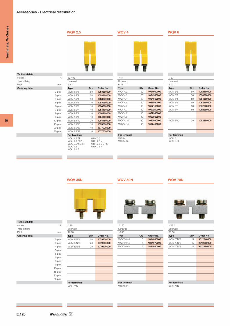
WQV 2.5
Type Qty Order No.
WQV 2.5/2 50 1053660000
WQV 2.5/3 50 1053760000
WQV 2.5/4 50 1053860000
WQV 2.5/5 10 1053960000
WQV 2.5/6 10 1054060000
WQV 2.5/7 10 1054160000
WQV 2.5/8 10 1054260000
WQV 2.5/9 10 1054360000
WQV 2.5/10 20 1054460000
WQV 2.5/15 10 1059660000
WQV 2.5/20 10 1577570000
WQV 2.5/32 10 1577600000
WDU 1.5 ZZ WDU 1.5 BLZ WDU 2.5/1.5 ZR WDU 2.5 WDU 2.5 F
32 / 32Screwed5.10
For terminal:WDK 2.5 WDK 2.5 V WDK 2.5 DU-PE WDK 2.5 F
WQV 4
/ 41Screwed6.10
Type Qty Order No.
WQV 4/2 50 1051960000
WQV 4/3 50 1054560000
WQV 4/4 50 1054660000
WQV 4/5 10 1057860000
WQV 4/6 10 1057160000
WQV 4/7 10 1057260000
WQV 4/8 10 1057960000
WQV 4/9 10 1058060000
WQV 4/10 20 1052060000
WQV 4/15 10 1057460000
For terminal:WDU 4 WDU 4 SL
WQV 6
/ 57Screwed8.00
Type Qty Order No.
WQV 6/2 50 1052360000
WQV 6/3 50 1054760000
WQV 6/4 50 1054860000
WQV 6/5 50 1062660000
WQV 6/6 50 1062670000
WQV 6/7 50 1062680000
WQV 6/10 20 1052260000
For terminal:WDU 6 WDU 6 SL
Technical datacurrent AType of fixingPitch mm
Ordering data
2-pole
3-pole
4-pole
5-pole
6-pole
7-pole
8-pole
9-pole
10-pole
15-pole
20-pole
32-pole
WQV 35N
Type Qty Order No.
WQV 35N/2 20 1079200000
WQV 35N/3 20 1079300000
WQV 35N/4 20 1079400000
WDU 35N
/ 101Screwed16.00
For terminal:
WQV 50N
/ 150Screwed18.50
Type Qty Order No.
WQV 50N/2 5 1834060000
WQV 50N/3 5 1834070000
WQV 50N/4 5 1834080000
For terminal:WDU 50N
WQV 70N
/ 192Screwed20.50
Type Qty Order No.
WQV 70N/2 5 9512240000
WQV 70N/3 5 9512250000
WQV 70N/4 5 9531290000
For terminal:WDU 70N
Term
inal
s, W
-Ser
ies
Accessories - Electrical distribution

E
E.129
WQV 10
/ 57Screwed10.00
Type Qty Order No.
WQV 10/2 50 1052560000
WQV 10/3 50 1054960000
WQV 10/4 50 1055060000
WQV 10/10 20 1052460000
For terminal:WDU 10 WDU 10 SL WDU 10 ZR
WQV 16
/ 76Screwed12.00
Type Qty Order No.
WQV 16/2 50 1053260000
WQV 16/3 50 1055160000
WQV 16/4 50 1055260000
WQV 16-4/6 10 1064000000
WQV 16/10 10 1053360000
For terminal:WDU 16
WQV 16N
/ 76Screwed12.00
Type Qty Order No.
WQV 16N/2 50 1636560000
WQV 16N/3 50 1636570000
WQV 16N/4 50 1636580000
For terminal:WDU 16N
WQV 35
/ 112Screwed16.00
Type Qty Order No.
WQV 35/2 50 1053060000
WQV 35/3 50 1055360000
WQV 35/4 50 1055460000
WQV 35-4/6 10 1064200000
WQV 35/10 10 1053160000
For terminal:WDU 35
WQV 70/95
232 / 192Screwed27.00
Type Qty Order No.
WQV 70/95/2 5 1063500000
WQV 70/95/3 5 1063600000
For terminal:WDU 70/95
WQV 95N/120N
269 / 269Screwed27.00
Type Qty Order No.
WQV 95N/120N- 5 1826890000
WQV 95N/120N- 5 1826900000
WQV 95N/120N- 5 1826910000
For terminal:WDU 95N/120N
WQV 120
269 / 269Screwed32.00
Type Qty Order No.
WQV 120/2 5 1063300000
WQV 120/3 5 1063400000
For terminal:WDU 120/150
Term
inal
s, W
-Ser
ies
Accessories - Electrical distribution
E
E.130
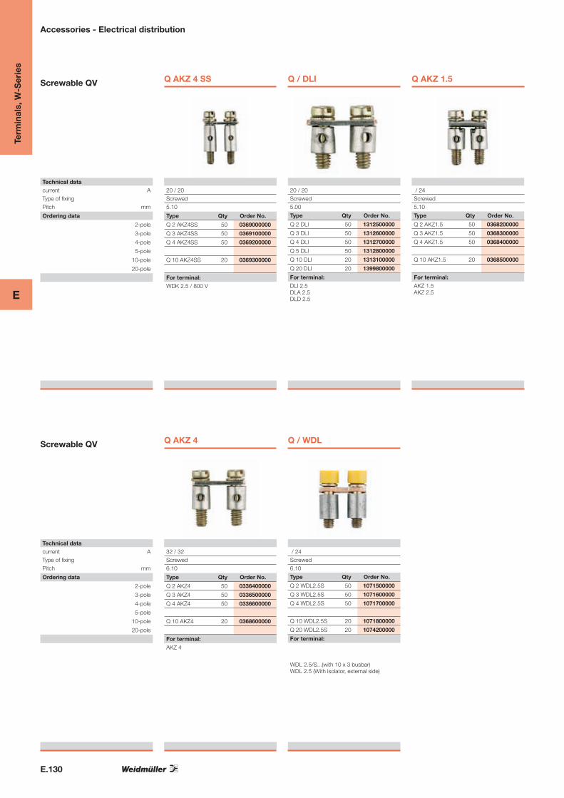
Screwable QV
Technical datacurrent AType of fixingPitch mm
Ordering data
2-pole
3-pole
4-pole
5-pole
10-pole
20-pole
Q AKZ 4 SS
Type Qty Order No.
Q 2 AKZ4SS 50 0369000000
Q 3 AKZ4SS 50 0369100000
Q 4 AKZ4SS 50 0369200000
Q 10 AKZ4SS 20 0369300000
WDK 2.5 / 800 V
20 / 20Screwed5.10
For terminal:
Q / DLI
20 / 20Screwed5.00
Type Qty Order No.
Q 2 DLI 50 1312500000
Q 3 DLI 50 1312600000
Q 4 DLI 50 1312700000
Q 5 DLI 50 1312800000
Q 10 DLI 20 1313100000
Q 20 DLI 20 1399800000
For terminal:DLI 2.5 DLA 2.5 DLD 2.5
Q AKZ 1.5
/ 24Screwed5.10
Type Qty Order No.
Q 2 AKZ1.5 50 0368200000
Q 3 AKZ1.5 50 0368300000
Q 4 AKZ1.5 50 0368400000
Q 10 AKZ1.5 20 0368500000
For terminal:AKZ 1.5 AKZ 2.5
Screwable QV
Technical datacurrent AType of fixingPitch mm
Ordering data
2-pole
3-pole
4-pole
5-pole
10-pole
20-pole
Q AKZ 4
Type Qty Order No.
Q 2 AKZ4 50 0336400000
Q 3 AKZ4 50 0336500000
Q 4 AKZ4 50 0336600000
Q 10 AKZ4 20 0368600000
AKZ 4
32 / 32Screwed6.10
For terminal:
Q / WDL
/ 24Screwed6.10
Type Qty Order No.
Q 2 WDL2.5S 50 1071500000
Q 3 WDL2.5S 50 1071600000
Q 4 WDL2.5S 50 1071700000
Q 10 WDL2.5S 20 1071800000
Q 20 WDL2.5S 20 1074200000
For terminal:
WDL 2.5/S...(with 10 x 3 busbar) WDL 2.5 (With isolator, external side)
Term
inal
s, W
-Ser
ies
Accessories - Electrical distribution

E.131
Term
inal
s, W
-Ser
ies
E
Accessories – Potential distribution
Cross-connections with test-disconnect terminal / fuse terminal WSI 6
Installation
Screw the cross-connection lugs QL X SAK6N directly to the current bar (Order No. 1052100000 KISC M3X5). To do this, push out the pre-punched side window of the terminal carrier with the help of tool WAW 2 (order No. 9004510000) and clip the terminal in place. Now open the fuse holder and insert the fixing screw. Slip the cross-connection lug in through the punched opening in the side of the terminal carrier and secure it with the fixing screw.Important! The side window of the last terminal may not be broken out asotherwise the rated voltage cannot be guaranteed.
Accessories for stud terminals
Potential distribution
The power distribution between neighbouring stud terminals can be achievedsimply with the use of 2- and 3-pole cross-connections (see the sectionunder stud terminals).
However, a cross-section reduction is required in special cases. Theseso-called cross-connection lugs are available for thread sizes from M6 toM10 and can be combined as required. This is helpful for power suppliesand power distribution, for example.
WQL 2 WF 6–10
WQL 3 WF 6–10/2
WQL 2 WF 6/8
Type Current
[A]
Qty. Order No. Primary stud
connection
[M...]
Neighbouring
stud connection
[M...]
WQL 2 WF 6–10 125 5 1806620000 WF 6 = 1 pole 1 x WF 10 = 1 pole
t = 4 mm M 6 M 10
WQL 3 WF 6–10/2 125 5 1806640000 WF 6 = 1 pole 2 x WF 10 = 2 polest = 4 mm M 6 M 10
WQL 2 WF 6/8 125 5 1808980000 WF 6 = 1 pole 1 x WF 8 = 1 polet = 4 mm M 6 M 8
WQL 4 WF 8–6/3 125 5 1904960000 WF 8 = 1 pole 3 x WF 6 = 3 polest = 4 mm M 8 M 6
WQL
Special cross-connection lugs

E.132
Term
inal
s, W
-Ser
ies
E
Accessories – Potential distribution
Technical data
Continuous current 2-pole/multi-pole A
Fork length mm
Ordering data
2-pole
3-pole
4-pole
10-pole
24-pole
Fixing screw
Releasing tool
24 / 24
12
Type Qty. Order No.QL 2 100 0194300000
QL 3 100 0194400000
QL 4 50 0194500000
QL 10 20 0338300000
BS-M 3 x 5 100 1052100000
WAW 2 1 9004510000Releasing toolWSI 6...
QL ... for WSI 6
Pitch 6.3 mm
WQB A / ...
Pitch 5.1 mm
WQB B / ...
Pitch 5.1 mm
External cross-connection bridges
Function
External cross-connection bridges allow for current to be bridged interminals without a cross-connection channel in the middle or when twopotentials are to be routed in parallel.
Assembly
These bridges are positioned over the conductor in the clamping pointand connected. Individual contacts can be separated off by hand whenyou wish to skip a clamping point. Important! Use of these parts reduces the nominal cross-section of theconnected conductor to the next smallest size for the terminal in question.
24 / 24
12
Type Qty. Order No.WQB A / 2 50 1578950000
WQB A / 3 50 1578960000
WQB A / 4 50 1578970000
WQB A / 10 50 1578990000
WQB A / 24 50 1579000000
Releasing toolWDK 2.5
24 / 24
16
Type Qty. Order No.WQB B / 2 50 1579010000
WQB B / 3 50 1579020000
WQB B / 4 50 1579030000
WQB B / 10 50 1579050000
WQB B / 24 50 1579060000
Releasing toolWDU 1.5 / ZZ (lower connection level)
WDU 2.5
WDU 2.5 / 1.5 / ZR (lower connection level)
WTR 2.5

E.133
Term
inal
s, W
-Ser
ies
E
Test plugs (PS) are used for measurements or final testing of ready wiredterminal strips. Test plugs are available for socket contacts with an internaldiameter of 2.3 mm or 4 mm.The difference to the test adapter is that the test plug does not slot into theterminal. This means that reliable plugging into feed-through terminals up to35 mm2 is only possible with a socket.
Special feature for large cross-sectionsWDU 70N, WDU 95N/120N, WDU 70/95, WDU 120/150In these terminals, test plug PS 4 can be plugged into the head of theclamping screw for measurements.
The StB socket is used for fitting the PS test plug. The sockets are screwedinto the busbar in the cross-connection channel in the middle of the terminal. The WTR test-disconnect terminals are available with pre-assembled sockets (refer to the W-Series test-disconnect terminals). The sockets are equipped with a slot for the screwdriver. A special screwdriver blade gua-rantees that the sockets are securely tightened (see catalogue 6, chapter F).
Combining with WQVThe socket can be used in combination with the WQV screw-in crosscon-nection. For this purpose, the insulating part of the screw and the fixingscrew have to be removed at the corresponding pole in the WQV. Thesocket can then be screwed in.
Testing in terminals
Accessories – Testing
PS
Test plug
StB
Socket
Ordering dataTest plug Qty. Order No.
2.3 mm diameter / rated current 17.5 A
PS 2.3 20 0180400000
4.0 mm diameter / rated current 24 A
PS 4 20 0299600000
Ordering dataSocket For test
plug
Qty. Order No. For standard
terminal
For compact
terminal
Thread M 2.5 / Length 11.5 mm
StB 8.5 PS 2.3 50 0215700000 WDU 1.5/ZZ WDU 2.5N (WQV)
WDU 2.5/1.5/ZR WDU 2.5N 600V UL
WDU 2.5
WDK 2.5…
Thread M 3 / Length 12 mm
StB 8.5 PS 2.3 50 0280600000 WDU 4
WDU 6
WDU 10
WDU 10/ZR
Thread M 3 / Length 19 mm
StB 14 PS 4 50 0169900000 WDU 10 WDU 16N
WDU 10ZR
Thread M 4 / Length 23 mm
StB 16 PS 4 50 0140200000 WDU 16 WDU 35N
Thread M 3 / Length 23 mm (finger-safe)
StB 21.6 PS 4 50 1071000000 WDU 4 WDU 6
WDU 10

E
E.134
Test adapter
DimensionsWidth / Length / Height mmStripping length mmRated dataRated voltage VRated current ARated cross-section mm²Clamped conductors (H05V/H07V)solid / stranded mm²flexible / Flexible with ferrule mm²
Ordering data
1-pole
With snap-in pegs
10-pole
WTA 1
Type Qty Order No.
WTA 1 WDU1.5 25 1632290000
WTA 1/ZA WDU1.5 25 1632300000
WDU 2.5N WDU 4N
5 / 66.1 / 98.26
IEC UL CSA250 300 3006 6 61.5
0.5...1.5 1...1.5 / 0.5...1.5
For terminal:
WTA 2
5 / 66.1 / 107.66
IEC UL CSA250 30061.5
0.5...1.5 1...1.5 / 0.5...1.5
Type Qty Order No.
WTA 2 WDU2.5-10 25 1632320000
WTA 2/ZA WDU2.5-10 25 1632330000
WTA 2/10 WDU2.5/10 5 1632340000
For terminal:WDU 1.5 ZZ WDU 2.5/1.5 ZR WDU 2.5 WDU 2.5 F
WDU 4 WDU 6 WDU 10 WDU 16
WTA 3
6 / 66.1 / 107.66
IEC UL CSA250 30061.5
0.5...1.5 1...1.5 / 0.5...1.5
Type Qty Order No.
WTA 3 WDU4 25 1632350000
WTA 3/ZA WDU4 25 1632360000
WTA 3/10 WDU4/10 5 1632370000
For terminal:WDU 4 WDU 6 WDU 10
Test adapter
DimensionsWidth / Length / Height mmStripping length mmRated dataRated voltage VRated current ARated cross-section mm²Clamped conductors (H05V/H07V)solid / stranded mm²flexible / Flexible with ferrule mm²
Ordering data
1-pole
With snap-in pegs
10-pole
WTA 6
Type Qty Order No.
WTA 6 WTR2.5 25 1632380000
WTA 6/ZA WTR2.5 25 1632390000
WTR 2.5
5 / 66.1 / 107.66
IEC UL CSA250 300 3006 6 61.5
0.5...1.5 1...1.5 / 0.5...1.5
For terminal:
WTA 7
6 / 68 / 1206
IEC UL CSA250 30061.5
0.5...1.5 1...1.5 / 0.5...1.5
Type Qty Order No.
WTA 7 WSI6 25 1650210000
For terminal:WSI 6
Term
inal
s, W
-Ser
ies
Accessories - Testing / checking

E
E.135
WTA 4N
5 / 62 / 111.6
IEC UL CSA250 30061.5
0.5...1.5 1...1.5 / 0.5...1.5
Type Qty Order No.
WTA 4N WDK 2.5 25 1878660000
WTA 4N/ZA WDK 2.5 25 1879350000
For terminal:WDK 2.5 WDK 2.5 V WDK 2.5 F WDK 2.5 FV
WTA 5
5 / 17 / 68.26
IEC UL CSA250 30060.75
0.5...1 1...1 / 0.5...1
Type Qty Order No.
WTA 5/1 25 1051260000
WTA 5/10 5 1062060000
For terminal:WDU 2.5 WDU 4 WDU 6
WDU 10 WDU 10 ZR
Test adapter
DimensionsWidth / Length / Height mmStripping length mmRated dataRated voltage VRated current ARated cross-section mm²Clamped conductors (H05V/H07V)solid / stranded mm²flexible / Flexible with ferrule mm²
Ordering data
red
red
green
green
beige
beige
WTA 8
Type Qty Order No.
WTA 8 TN-KO/ZA 25 1915520000
WTA 8 TN-KO 25 1915470000
WTA 8 KO-TN/ZA 25 1915510000
WTA 8 KO-TN 25 1915480000
WTA 8 TN/ZA 25 1915500000
WTA 8 TN 25 1915450000
WTL 4/2 StB
6 / 39 / 78
IEC UL CSA20561.5
0.5...2.5
For terminal:
TN-KO = Isolate - Contact KO-TN = Contact - Isolate TN = Isolate
Term
inal
s, W
-Ser
ies
Accessories - Testing / checking

E
E.136
Labelling / cover
The WAD cover is snapped on to the centre of the terminal on the cross-connection channel, from the top down. The covers are delivered in yellow with a black lightning flash symbol and also in white without markings. The WAD covers are available for all feed-through terminals in the W-Series. Labelling of mains terminals VDE regulations require that mains terminals be labelled with „Warning Voltage“ and a lightning flash symbol. Convenient labelling options A white cover with no print is well suited for manual terminal la-belling or for group labelling. Touch protection with uninsulated cross-connections Important! When cross-connecting the WDU 70N, WDU 95N/120N, WDU 70/95 and WDU 120/150, touch protection is guaranteed by the cover, in compliance with VDE directives.
Term
inal
s, W
-Ser
ies
Accessories - Marking
WAD
Type Colour Qty Order No. For terminal:Width
WAD 4 GE BED yellow 50 1072000000
WAD 4 WS white 50 1072100000
WDK 2.5
WDK 2.5 / 800V
WDK 2.5 BL
WDK 2.5 DU-PE
WDK 2.5 F
WDK 2.5 F BL
WDK 2.5 FF
WDK 2.5 FV
WDK 2.5 ZQV
WDK 2.5 ZQV BL
WDK 2.5/D
WDK 2.5V
WDK 2.5V BL
WDU 1.5/ZZ
WDU 1.5/ZZ BL
WDU 2.5 F 2X2.8
WDU 2.5 FF 2*2.8
WDU 2.5N
WDU 2.5N BL
WDU 2.5N ZQV
WDU 2.5N ZQV BL
WDU 2.5N/600 UL
WDU 4N
WDU 4N BL
Width
WAD 5 NEUTRAL white 50 1056060000
WAD 5 M. BL. yellow 50 1053460000
WDU 2.5
WDU 2.5 BL
WDU 2.5/1.5/ZR
WDU 2.5/1.5/ZR BL
WDU 4
WDU 4 BL
WDU 6
WDU 6 BL
Width
WAD 8 NEUTRAL white 50 1056160000
WAD 8 M. BL. yellow 50 1053560000
WDU 10
WDU 10 BL
Width
WAD 12 NEUTRAL white 50 1056260000
WAD 12 M. BL. yellow 50 1055960000
WDU 16/ZA
WDU 16/ZA BL
WDU 16N BL
WDU 35/IK/ZA
WDU 35/ZA
WDU 35/ZA BL
Width
WAD 12N GE BED yellow 50 1073200000
WAD 12N WS white 50 1073290000
WDU 16N
Width
WAD 16N GE BED yellow 50 1083600000
WAD 16N WS white 50 1083500000
WDU 16N
WDU 35N
WDU 35N BL
Width
WAD 20 GE WSD yellow 10 9512260000
WAD 20 WS white 10 9512270000
WDU 50N
WDU 50N BL
WDU 70N/35
WDU 70N/35 BL
WDU 95N
WDU 95N BL
Width
WAD 27 NEUTRAL white 10 1062960000
WAD 27 M. BL. yellow 10 1062860000
WDU 120
WDU 120 BL
WDU 70/95
WDU 70/95 BL

E.137
Term
inal
s, W
-Ser
ies
E
without LEDQty. Order No.
SIHA3/G20
400 V 1 7921560000
with LED (red)
SIHA3/G20 10 - 36 V 1 7921570000
35 - 70 V 1 7921580000
60 - 150 V 1 7921590000
140 - 250 V 1 7921600000
For test-disconnect terminal versionsWTR 4
WTR 4/ZZ
WTR 4/ZR
WTR 2.5
without LEDQty. Order No.
SIHA1/G20
400 V 1 9537550000
with LED (red)
SIHA1/G20 10 - 36 V 1 9537560000
35 - 70 V 1 9537570000
60 - 150 V 1 9537580000
140 - 250 V 1 9537590000
For test-disconnect terminal versionsWTR 2.5/ZZ
SIHA 3SIHA 1 SIHA STRAP
with strapQty. Order No.
SIHA STRAP
20 9537680000
Connector for “retro-fit” assembly
• Receptacleintheterminalisthemarking
position
• Integratedmarkingpositiononthestrap
• Slotsintofuseholdereitherleftorright
Accessories – Specific functions and variations
SIHA fuse holder
For 5x20 G-fuse cartridges
TheSIHAfuseholderturnsatest-disconnect terminal into a fuse terminal in seconds:
Simplyremovetheisolatingleverandinsertthefuseplug
• Simplehandling–notools required
• HousingmadeofWemid(V0)
• Ratedcurrent6.3A
• 1.6WpowerlosstoDINVDE0611-6 at 23 °C ambient temper-ature (also for 1.5 times rated current–compositearrangement)
• Evenfitson5mmwideterminalswhenfittedinoffsetarrangement
• MarkingpositionforDekafix5andspaceforself-adhesive label size 8/20
▲
▲
▲
▲
2. Press out old fuse
4.Pressfuseholdertogetheragain
1. Openfuseholderwithfingers orscrewdriver
3. Position new fuse

E.138
Term
inal
s, W
-Ser
ies
E
Ordering dataG-type cartridge fuses 5x20 without indicatorstoIEC60127-2(VDE0820pt.2Bl1) Qty. Order No.Size (mm) Nom. current (A) Type
0.1 (F) G20/0.10A/F 10 0430300000
5x20 0.2 (F) G20/0.20A/F 10 0430400000
breakingcapacity1500A 0.25 (F) G20/0.25A/F 10 0430500000
(at250V,50Hz,cos: 0.7) 0.5 (F) G20/0.50A/F 10 0430600000
0.63 (F) G20/0.63A/F 10 0439000000
1.0 (F) G20/1.00A/F 10 0430700000
1.6 (F) G20/1.60A/F 10 0430800000
2.0 (F) G20/2.00A/F 10 0430900000
2.5 (F) G20/2.50A/F 10 0431000000
3.15 (F) G20/3.15A/F 10 0431100000
4.0 (F) G20/4.00A/F 10 0431200000
5.0 (F) G20/5.00A/F 10 0431300000
6.3 (F) G20/6.30A/F 10 0431400000
(M)=medium-blow(F)=fast-blow
G-type cartridge fuses5x25with indicatorstoDIN415761)
5x25w.indicator1)
breakingcapacity80A
(at250V,50Hz,cos:=1
0.25 (M) G25/0.25A/M 10 0546900000
0.5 (M) G25/0.50A/M 10 0510300000
0.8 (M) G25/0.80A/M 10 0646400000
1 (M) G25/1.00A/M 10 0265800000
10 (M)5) G25/10.0A/M 10 0193100000
2 (F) G25/2.00A/F 10 0192700000
4 (F) G25/4.00A/F 10 0192800000
6.3 (F) G25/6.30A/F 10 0192900000
(M)=medium-blow(F)=fast-blow
Cartridge fuses 1¼"x¼"without indicatorstoBS88
33kAbreakingcapacity,33kAfast-blow 0.5 GZ0.5A/F 10 0533800000
E0.5A
E1 A
E2 A
E3 A
E5 A
E7 A
E10 A
1 GZ1.0A/F 10 0525500000
2 GZ2.0A 10 0294500000
3 GZ3.0A 10 0295700000
5 GZ5.0A 10 0294600000
7 GZ7.0A 10 0295800000
10 GZ10.0A 10 0293900000
12.5 GZ12.5A/FF 10 0245400000
(F)=fast-blow(M)=medium-blow
D-type cartridge fuses E 16 with indicatorstoDIN49360(Diazed)
E10 A
E16 A
E20 A
E25 A
10 E16/10ART 25 0208500000
16 E16/16AGR 25 0208600000
20 E16/20ABL 25 0208700000
25 E16/25AGE 25 0208800000
(F)=fast-blow(M)=medium-blow
D-type cartridge fuses E 14 size D 01 and E 18 size D 02 with indicatorstoDIN49522(Neozed)3)
E 14/2
E 14/4
E 14/6
E 14/10
2 E14/2ARS 10 0137400000
4 E14/4ABR 10 0137500000
6 E14/6AGN 10 0328300000
10 E14/10ART 10 0328400000E 14/16 16 E14/16AGR 10 0328500000
E 18/20
E 18/25
E 18/35
E 18/50
20 E18/20ABL 10 0361300000
25 E18/25AGE 10 0361400000
35 E18/35ASW 10 0361500000
50 E18/50AWS 10 0361600000
E 18/63 63 E18/63AKU 10 0361700000
(F)=fast-blow(M)=medium-blow
Notes: 1)SIBAalsosuppliesG-typecartridgefuses5x25withindicatorssuitablefor450V~shipbuildingapplications. 2)Cartridgefuses5x30(500V~)forSAKS3areavailablefromtheWICKMANNcompany. 3)LINDNERalsosuppliestheNeozedcartridgefusesinanotherversionsuitablefor440V~shipbuildingapplications. 4)Cartridgefusesinthesizes1“x¼“(25.4x6.35mm)and13/32“x1½“(10.3x38.1mm)arenotincludedintherange. 5)ForSAKS1andSAKS7only.
Cartridge fuses
Technical data For terminal type
WSI4
WSI6
WSI6
WSI4/2
WSI6/2
SAKS2
SAKS44)
SAKS5
Accessories – Specific functions and variations

E.139
Term
inal
s, W
-Ser
ies
E
Ordering dataGauge piece type Amps Colour Type Qty. Order No.
P 14/2 2 pink P14/2D01RS 50 0138000000
P 14/4 4 brown P14/4D01BR 50 0138100000
P 14/6 6 green P14/6D01GN 50 0328600000
P 14/1 10 red P 14/10D01 RT 50 0328700000
P 18/20 20 blue P18/20D02BL 50 0361800000
P 18/25 25 yellow P 18/25D02 GE 50 0361900000
P 18/35 35 black P18/35D02SW 50 0362000000
P 18/50 50 white P18/50D02WS 50 0362100000
P 16/10 10 red P 16/10 RT 100 0208900000
P 16/16 16 grey P 16/16 GR 100 0209000000
P 16/20 20 blue P16/20BL 100 0209100000
Gauge pieces
Technical dataFor terminal type
SAKS4/35
SAKS5/35
SAKS2/35
Accessories – Specific functions and variations
The Weidmüller philosophy is to realise a multitude of applications with just a few parts. The compo-nentandisolatingplugs(BESTandTNST)repre-sentalogicalextensionofthiscost-effectiveandefficientapproach.Thecomponentplugcanaccommodate electronic components and connect themtotheterminal.Andonceanisolatingplugisremoved,theclampingpointisobviouslydiscon-nected.Theopeningiseasytorecognise.
Anunintentionalreconnectionofthecircuitispreventedbysimplyremovingtheisolatingplug.TheBESTandtheTNSThavethesamepinarrangement.BothplugsarealsoidenticalwiththeSIHA3fuseholder,meaningthattheycanbeusedinallthe“disconnectingproducts”oftheW-,Z-,I-andP-Series.
Component isolating plugs
Ordering dataType Colour Qty. Order No.
TNST Wemid, yellow 25 1833090000
For terminal type
WTR 2.5
WTR 4
WTR 4/ZZ
WTR 4/ZR
Ordering dataType Fitted with… Qty. Order No.BEST without 25 1833100000
BEST/DRBR wire jumper 25 1878570000
BEST/D diode1N4007 25 1878560000For terminal type
WTR 2.5
WTR 4
WTR 4/ZZWTR 4/ZR
Isolating plug
Component plug (up to 250 V)
canbereversed
BEST

E.140
Term
inal
s, W
-Ser
ies
E
Accessories – Specific functions and variations
Screen plug (LS)
Ascreenplug(LS)isavailableformanyterminalsintheW-Series.Thebar can be used to continue the shieldingovertheterminalsasanin-terface. There is no direct connec-tion to earth potential.
Assembly
Thescreenplugisplacedflatinthebottom of the terminal in the recess provided.Attheends,theshieldcanbepluggedinwitha2.8mmFastonconnector or also soldered on.
Reduced rated voltage
Thesmallerclearanceandcreepagesectionsresultinareducedvoltageratingintheterminalwhenusingthescreenplug.
LS 2.8Type Qty. Order No.
LS2.8WDU2.5-10 50 1056400000
Reduced voltageFor standard Reducedterminal voltage WDU1.5/ZZ 400 V
WDU2.5/1.5/ZR 400 V
WDU2.5 400 V
WDU4 400 V
WDU6 400 V
WDU10 400 V
WDK2.5ZQV 250 V
WDK2.5(WQV) 250 V
WTR 2.5… 250 V
For compact Reduced
terminal voltageWDK2.5N 250 VWDK4N 250 V
WDSType Qty. Order No.
WDS2 20 1069900000
Reduced voltageFor terminal
WDU1.5/ZZ
WDU2.5/1.5/ZR
WDU2.5
WDK2.5…(WQV)
WTR 2.5…
WDU2.5F…
WZADType Clamped Rated Qty. Order No. For terminal
conductor currentWZAD70/95 up to 4 mm2 32A 10 1066000000 WDU70/95
WZAD120/150 up to 4 mm2 32A 10 1066100000 WDU120/150
WZAD240 up to 10 mm2 57A 5 1802810000 WDU240
WZAD50N up to 10 mm2 40A 5 1872720000 WDU50N
WZAD70N up to 4 mm2 32A 10 9512280000 WDU50N/70NWZAD95N/120N up to 10 mm2 41A 5 1959580000 WDU95N/120N
WZADType Clamped Rated Qty. Order No. For terminal
conductor currentWZAF35 4 mm2 32A 10 1070500000 WFF 35
WZAF70 4 mm2 32A 10 1066200000 WFF 70
WZAF120 4 mm2 32A 10 1066300000 WFF 120
WZAF185 4 mm2 32A 10 1066400000 WFF 185
WZAF300 4 mm2 32A 10 1066500000 WFF 300
Short-circuit plug (WDS)
Short-circuitplugs(cross-connectionplugs)areusedtogetherwithsock-ets (diameter 2.3 mm) for easily dis-connected cross-connection of ter-minals.
Intherealworld,thisconnectorisusedveryoftenwithtest-disconnectterminals.Thankstoitsinsulatedgrip,theWDSistouch-safe.
Assembly
Theplugissimplypluggedontothesocketandlocksautomatically.
For terminal width 5.1 mm
Extension connector (WZAD)
Anextensionconnector(WZAD)isofferedforfeed-throughterminalsfrom 70 mm2.
Assembly
This connector consists
of a metal part which is pushed into theterminalandlodgesbehindtheclampingyoke.TheWZADexten-sion connector is connected to the “main” conductor in the terminal. Anotherconductorofupto4mm2 and32Acanbescrewedtotheout-erendoftheextensionconnectorusingaringcablelug.
ExceptionWZADWDU240
TheextensionconnectorforWDU240isseparatelypluggedintotheterminalabovethewireentryandlocksautomatically.Theconductoris connected with a fully insulated screw connection.

E.141
Term
inal
s, W
-Ser
ies
E
PEN bridges
Accessories – Specific functions and variations
Energydistributionformachinesorinbuildingsusuallyconsistsof5-conductorsystems(TN-S).Bycontrast,energysupplymainsarefrequently rated as 4-conductor connection.APENbridgejoinssep-aratePEandNconductorsintoonePENconductor,creatingthetransi-tionfromaTN-StoaTN-Csystem.
Standard installation
Dependingontheterminaltype,
insideoroutsidePENbridgesareavailableforbothPEandNconduc-tor terminals from 10 mm2
Important!Foroutsidebridges,pleasenotethatinthiscontextonlythenextsmallerratedcross-section(than standard) can be connected.
Building installation with N-conductor isolation
Specialexternalcross-connections(WQB-PEN)areavailableforneutral-conductor test-disconnect terminals (WNT).Theseestablishcontactbe-tweentheNTandPEterminals.Thisresults in an earthed neutral conduc-tor with protection function in three-phase systems.
TN-C system:TN-C-Netz
B
N
PE
L1L2L3PEN
TN-S-Netz
B
PE
L1L2L3NPE
TN-S system:
External PEN bridge
WQB-PEN …Type Qty. Order No. For terminal
with standard terminals
WQB-PEN10 10 1060300000 WPE 10
WDU10BL
WQB-PEN16 10 1060200000 WPE 16WDU16BL
WQB-PEN3 10 1060100000 WPE35N
WDU35NBL
with neutral-conductor test-disconnect terminals
WQB-PEN16N 10 1079600000 WNT16N
WPE16N
WQB-PEN35N 10 1079500000 WNT35NWPE35B
WQB-PEN70N 10 1079700000 WNT70NWPE70N
Inside PEN bridge
WQV … -PENType Qty. Order No. For terminal
WQV16N-PEN 10 1071360000 WPE16N
WDU16NBL
WQV70N-PEN 5 9201620000 WPE70NWDU70NBL
WQV70/95-PEN 5 1072300000 WPE70/95WDU70/95BL
WQV120-PEN 5 1072400000 WPE 120/150WDU120/150BL
WQV50N-PEN 9201610000 WPE50NWDU50N
WQV95N/120N-PEN 9201620000 WPE95N/120NWDU95N/120N

E
Term
inal
s, W
-Ser
ies
E.142
Accessories – Colour alternatives
The colours listed are available as standard. Other terminal types can be supplied in customised colours on request for quantities exceeding the minimum quantity.
Standard design Compact designColour Qty Order No. Colour Qty Order No.
WDU 2.5 WDU 2.5WDU 2.5 OR orange 1020060000 WDU 2.5N OR orange 1023760000
WDU 2.5 BR brown 1037710000 WDU 2.5N GE yellow 1023790000WDU 2.5 GE yellow 1020020000 WDK 4N
WDU 2.5 GN green 1020090000 WDK 4N OR orange 1041960000
WDU 2.5 GR grey 1037720000
WDU 2.5 RT red 1020040000
WDU 2.5 SW black 1020010000
WDU 2.5 VI violet 1037700000
WDU 2.5 WS white 1036800000WDK 2.5WDK 2.5 OR orange 1021560000
WDK 2.5 WS white 1790900000WDK 2.5 VWDK 2.5 V OR orange 1022360000
WDK 2.5 V GE yellow 1022350000WDU 4WDU 4 OR orange 1036760000
WDU 4 BR brown 1037810000
WDU 4 GE yellow 1020120000
WDU 4 GN green 1020160000
WDU 4 GR grey 1037800000
WDU 4 RT red 1020140000
WDU 4 SW black 1020110000
WDU 4 VI violet 1037820000
WDU 4 WS white 1036700000WDU 6WDU 6 OR orange 1020260000
WDU 6 GE yellow 1040220000
WDU 6 GR grey 1039600000
WDU 6 RT red 1020240000
WDU 6 SW black 1020210000WDU 10WDU 10 OR orange 1020360000
WDU 10 GR grey 1020320000
WDU 10 RT red 1020340000WSI 6WSI 6 OR orange 1011060000
WSI 6 SW black 1011010000
WSI 6 BL blue 1011080000WTD 6/1WTD 6/1 GE yellow 1631760000
WTD 6/1 GR grey 1017120000
WTD 6/1 RT red 1631750000
WTD 6/1 SW black 1631770000WTL 6/3WTL 6/3 BR brown 1018640000WTL 6/3 GR green 1018850000

E
Term
inal
s, W
-Ser
ies
E.143
Accessories – Colour alternatives
WDU 2.5 Qty Oder No. Description
WDU 2.5/10 BEZ 10 1020700000 10 x WDU 2.5, identified by printed marking strip DEK 5
(nos. 1 – 9)
WDU 2.5/10 BEZ/NE 10 1020800000 10 x WDU 2.5, with blank marking strip DEK 5
WDK 2.5
WDK 2.5/10 10 1025700000 10 x WDK 2.5 (WQV), with blank marking strip DEK 5
WDK 2.5 ZQV/10/BEZ 10 1025610000 10 x WDK 2.5 (ZQV), identified by printed marking strip DEK
(nos. 1-9)
WDU 4
WDU 4/10/BEZ 10 1020900000 10 x WDU 4, identified by printed marking strip DEK 6
(nos. 1-9)
WDU 4/10 10 1021000000 10 x WDU 4 identified by blank marking strip DEK 6
WMA 4/4 20 1034000000 3 x WDU 4 (marked L1, L2, L3), WPE 4 (marked PE)
WMA 4/5 20 1033800000 3 x WDU 4 (marked L1,L2,L3), DEU 4 in blue (identified by N),
WPE 4 (marked PE)
WDU 70/95
WDU 70/95/3 4 1026700000 3 x WDU 70/95
WDU 70/95/5/N 2 1032300000 mains terminal block, 3x WDU 70/95 dark beige, 1x WDU 70/95 blue,
1 x WDU 70/95 green
WDU 120/150
WDU 120/150/5 2 1026600000 5 x WDU 120/150
WDU 120/150/5/N 2 1032400000 mains terminal block, 3 x WDU 120/150 dark beige,
1 x WDU 120/150 blue, 1 x WDU 120/150 green
WDL 2.5
WDL 2.5/3/S/NT/L/PE 25 1034200000 3 x WDL 2.5/S/NT/L/PE
WDL 2.5/2/NT/L/PE-L/L 20 1034100000 WDL 2.5/S/NT/L/PE and WDL 2.5/S/L/L
AKZ 1.5
AKZ 1.5/10 10 0358060000 10 x AKZ 1.5
AKZ 1.5/10/BEZ 10 0358160000 10 x AKZ 1.5, identified by printed marking strips DEK 5
(nos. 1-9)
AKZ 4
AKZ 4/10 10 0359560000 10 x AKZ 4
AKZ 4/10/BEZ 10 0359660000 10 x AKZ 4, identified by printed marking strips DEK 5
(nos. 1-9)
Compact design Qty Oder No. Description
WDU 2.5N
WDU 2.5N/10 BEZ/NE 10 1024800000 10 x WDU 2.5N, identified by printed marking strips DEK 5 (nos. 1-9)
Pre-fitted terminal blocks
Readily assembled and marked terminal blocks are available as a standard feature for smaller cross-section ranges.
Installation times can be reduced by simply slotting on complete blocks. The rating data depend on the corresponding terminal type.
Important!
• Tolerancesformountingmustbeheededin
project planning. A mounting tolerance of
+0.1 mm must be expected for each terminal.
• Interminalblocksmarked1–9,the10th
terminal is free for decade marking
• TerminalblocksWDU70/95andWDU120/150
for direct mounting only.
For direct mounting without the terminal rail
please take notice of the drilling plan. Fixing with
screw M6x16. (Order No. 1063700000/ VPE 20)
Drilling plan
WFF 185 / WFF 185 M 12 + M 16
WFF 120
WFF 70
WFF 35
WDU 70/95
WDU 120/150
75
627
632
100
100
16426
42
100
55
55
6
23.1
5
100
627
WDU 70/95
632
100
WDU 120/150
WFF 35
WFF 70
WFF120
WFF 185/300
75
627
632
100
100
16426
42
100
55
55
6
23.1
5
100
627
WDU 70/95
632
100
WDU 120/150
WFF 35
WFF 70
WFF120
WFF 185/300
75
627
632
100
100
16426
42
100
55
55
6
23.1
5
100
627
WDU 70/95
632
100
WDU 120/150
WFF 35
WFF 70
WFF120
WFF 185/300
75
627
632
100
100
16426
42
100
55
55
6
23.1
5
100627
WDU 70/95
632
100
WDU 120/150
WFF 35
WFF 70
WFF120
WFF 185/300
75
627
632
100
100
16426
42
100
55
55
6
23.1
5
100
627
WDU 70/95
632
100
WDU 120/150
WFF 35
WFF 70
WFF120
WFF 185/300
WFF 300
75
627
632
100
100
16426
42
100
55
55
6
23.1
5
100
627
WDU 70/95
632
100
WDU 120/150
WFF 35
WFF 70
WFF120
WFF 185/300
75
627
632
100
100
16426
42
100
55
55
6
23.1
5
100
627
WDU 70/95
632
100
WDU 120/150
WFF 35
WFF 70
WFF120
WFF 185/300

E
Term
inal
s, S
AK
-Ser
ies
E.144
Overview SAK-Series
SAK-Series / Clamping yoke screw connection technology
Terminal type Rated cross-section Flat-blade Faston- Spring- Solder 2.5 mm2 4 mm2 6 mm2 10 mm2 16 mm2 35 mm2 connection connection loaded connection
Feed-through terminals
PA 6.6 / TS 32 • • • • • • • • •
KRG / TS 32 • • • • • • • • • •
PA 6.6 / TS 35 • • • • • • • • •
KRG / TS 35 • • • • • • •
PA 6.6 / combination foot • • • • • •
PA 6.6 / TS 15 • • • •
Double level terminals •
PE terminals
PA 6.6 / TS 32 • • • • •
PA 6.6 / TS 35 • • • • • •
PA 6.6 / TS 15 • •
Fuse terminals
PA 6.6 / TS 32 •
PA 6.6 / TS 35 •
KrG / TS 32 • •
KrG / TS 35 • •
PA 6.6 / TS 15 •
PA 6.6 / combination foot •
Double level fuse terminals
PA 6.6 / TS 32 •
PA 6.6 / TS 35 •
PA 6.6 / combination foot •
Disconnect test terminal blocks
TS 35 • •
PA 6.6 / TS 15 •
Two-tier disconnect test terminals • •
Ceramic terminals • •
• Put to the test billions of times Countless approvals, specifications and the world’s most extensive range of terminals mean that SAK terminals can be used for a wide range of different applications.
• The right materials for every application Ambient temperatures are not an issue for the SAK-Series thanks to different materials such as polyamide, thermo- plastics and heat-resistant ceramics.
• Best conductivity and high contact force Thanks to its design, the legendary high-strength steel screw clamp absorbs every geometric change to the connected conductor.
• Cross-sections from 0.5 to 35 mm2
• TS 32/TS 35 “2 in 1” combination foot
• Cross-sections from 0.5 to 95 mm2
• Special foot for TS 35• Special foot for TS 32
Versions
All materials checked for conformity with the latest environmental directives and RoHS requirements.
Product assortment

E
Term
inal
s, S
AK
-Ser
ies
E.145
Overview SAK-Series
The connection Separation of electrical and mechanical functions: • Clamping yoke and clamping screw
made from hardened steel for high contact forces.
• A copper current bar for a low through resistance. The tin-plated surface guarantees minimum contact resistance.
• Gas-tight clamping point.• Clamping point suitable for a wide
range of cross-sections.
Cross-connection channel
• Any number of poles can be created by stacking the pre-fitted cross- connections.
Easy to use
• Built-in reserve when undoing the clamping screw – particularly important for mechanical screwing tools.
• Recessed clamping screw position provides guide for screwdriver.
• All parts fitted captive within the terminal.
• Numerous labelling options.
Reliable contact
• The steel clamping yoke compensates for temperature-induced changes to the conductor (no gradual loosening) required.
• Low-maintenance, vibration-resistant connection – no need to retighten the clamping screw.
• The highest contact force of any con-nection system – and in a compact space.
Safe to use
• Terminals supplied with open clamping point
• Yoke tab prevents incorrect insertion of conductors.
Standards and directives
The reliable contact and dependability of the Weidmüller systems are verified by: • Type tests to IEC 6047-7-1/2• National and international approvals• A large portfolio of UL and CSA
approvals• ATEX approval• IECEx approved
Insulating materials and max. temperatures • PA – 100 °C• KrG – 130 °C• EP – 160 °C• Ceramic – 250 °C
T
1 2 3
4 5
2
33
6
4
1
5
3 different snap-on feet6

E
Term
inal
s, S
AK
-Ser
ies
E.146