Embed Size (px)
Citation preview

SES2000AUTOCLAVES
erv
ice M
anual
ST-SM8l699215

Ser
vice
Man
ual
Introduction
Description
Maintenance
Illustrated parts list
Read these Instructions before use
Keep these instructions in a safe convenient place for future reference. Read in conjunctionwith the Publications detailed in Section 1.5.
This Service Manual applies to the following Autoclave REF numbers. (Note: In the parts listsection reference is also made to parts required for earlier versions) :-
SES 2000 STANDARD (from Serial Number - SCB8B0000, or SED8B0000 for non-CE)without printer : 87-028-04 87-028-20 87-028-36 87-029-05 87-029-13 87-029-21
87-029-37 87-029-45 87-029-54 87-029-62 87-029-70 87-029-7887-029-86 87-030-03 87-030-11 87-030-27 87-030-43 87-030-6087-031-03 87-031-68
with printer : 87-028-12 87-028-28 87-028-44 87-029-26 87-030-65 87-031-1187-031-76
SES 2000 LONG (from Serial Number - LSCB8B0000, or LSED8B0000 for non-CE)without printer : 87-028-53 87-028-69 87-028-85 87-028-90 87-028-97 87-029-29
87-029-94 87-030-70 87-031-19 87-031-84 87-020-05 87-022-0187-022-17 87-020-21 87-022-49 87-022-66
with printer : 87-028-61 87-028-77 87-030-75 87-031-27 87-031-92 87-020-1387-022-09 87-022-25 87-020-29 87-022-58 87-022-74
(Note: The alpha parts of the SN are significant.)
Eschmann After Sales Service Department
The Eschmann After Sales Service Department is staffed and equipped to provide advice andassistance during normal office hours. To avoid delays when making enquires, please quote theModel and Serial Number of your Autoclave. Please ensure you include all alpha and numericdigits of the Serial Number. (NOTE: The Serial Number Plate is located inside the door in the topleft hand corner).
For further information visit www.eschmann.co.uk
All correspondence relating to the after sales service of Eschmann Equipment to be addressed to :
UK CustomersEschmann Equipment, Peter Road, Lancing, West Sussex BN15 8TJ, England.Tel: +44 (0) 1903 765040. Fax: +44 (0) 1903 875711.
Overseas CustomersContact your local distributor. In case of doubt contact Eschmann Equipment.
Patents and Trade marks
The ESCHMANN name and logo are trade marks of Eschmann Holdings Limited.“Eschmann Equipment” is a trading name of Eschmann Holdings Limited.“SES2000” is a trade mark of Eschmann Holdings Limited.
Patents : Patents Pending plus - Pat. US5090033 and Pat. GB2238407
Copyright © 2008 Eschmann Holdings Limited
All rights reserved. This booklet is protected by copyright. No part of it may be reproduced, stored in aretrieval system or transmitted in any form or by any means, electronic, mechanical, photocopying,recording or otherwise without written permission from Eschmann Holdings Limited.The information in this publication was correct at the time of going to print. The Company, however,reserves the right to modify or improve the equipment referred to.
The CE marking affixed to the product certifies that it complies with theEuropean Medical Devices Directive 93/42/EEC and related legislation.
ST-SM8l November 2008

ST-SM8l Page 3 of 43
SES 2000 AUTOCLAVE
CONTENTS
Page
Contents .. .. .. .. .. .. .. .. 3Technical data .. .. .. .. .. .. .. 4
PART 1 INTRODUCTION
General .. .. .. .. .. .. .. .. 6Associated publication .. .. .. .. .. 6Servicing .. .. .. .. .. .. .. .. 6
PART 2 DESCRIPTION
General .. .. .. .. .. .. .. .. 7Operating features .. .. .. .. .. .. 7Operation cycle .. .. .. .. .. .. 9
Operation .. .. .. .. .. .. .. 9Display messages .. .. .. .. .. .. 10Error indication .. .. .. .. .. .. 11
General .. .. .. .. .. .. .. 11Overheating .. .. .. .. .. .. 11
PART 3 MAINTENANCE
Fuses .. .. .. .. .. .. .. .. 15Fault diagnosis and table .. .. .. .. 15Parts replacement and adjustment .. .. 20
Removing cover .. .. .. .. .. .. 20Refitting cover .. .. .. .. .. .. 20Thermal fuse .. .. .. .. .. .. 20Transformer.. .. .. .. .. .. .. 20Controller board .. .. .. .. .. .. 20Pressure door lock .. .. .. .. .. 20Air valve .. .. .. .. .. .. .. 21Door interlock switch .. .. .. .. .. 21Solenoid door lock (CE only) .. .. .. 22Heater cycling thermostat .. .. .. .. 22Temperature sensors .. .. .. .. .. 22Fill and Discharge valves .. .. .. .. 22Solid state relay (Non-CE) .. .. .. 22Solid state relay (CE only) .. .. .. 23Mechanical relay (CE only) .. .. .. 23Heating element .. .. .. .. .. .. 23Printer interface board .. .. .. .. 23Voltage regulators .. .. .. .. .. 23Door seal .. .. .. .. .. .. .. 23Pressure gauge .. .. .. .. .. .. 23Discharge line filter .. .. .. .. .. 24Printer .. .. .. .. .. .. .. 24
Special operating modes .. .. .. .. 24Demonstration mode .. .. .. .. .. 24Engineering mode .. .. .. .. .. 24Set-up mode .. .. .. .. .. .. 25Switch identities and function .. .. .. 25Power-on modes .. .. .. .. .. 25
PageSet-up procedure .. .. .. .. .. 26
Autoclave without printer .. .. .. 26Autoclave with printer .. .. .. .. 26Setting the Autoclave Serial Number 26Entering the Autoclave Serial Number 27Entering the date and time.. .. .. 27
Errors and error clearing .. .. .. .. 28General .. .. .. .. .. .. .. 28Control sensor selection .. .. .. .. 28Autocheck .. .. .. .. .. .. .. 28
Routine Autoclave Calibration .. .. .. 28General .. .. .. .. .. .. .. 28Calibration procedure .. .. .. .. 29
Safety valve .. .. .. .. .. .. .. 29Operational test .. .. .. .. .. .. 30
PART 4 ILLUSTRATED PARTS LISTS
Pipes and fittings, latest models .. .. .. 30Illustrated parts list 1: Pipes and valves .. 31Illustrated parts list 2: General spares .. 33Illustrated parts list 3:Heater and process controls .. .. .. .. 35
ILLUSTRATIONS
Fig. 1 SES 2000 Autoclave .. .. .. .. 6Fig. 2 Autoclave General Arrangement .. 12Fig. 3 Autoclave: Pipes and Valves .. .. 13Fig. 4 Autoclave: Heater & Process Controls 14Fig. 5 Door interlock microswitch .. .. 21Fig. 6 Filter unit disassembly .. .. .. 24Fig. 7 Switch identities and function .. .. 25Fig. 8 Autoclave Controller boards .. .. 30Fig. 9 Pipes and valves .. .. .. .. 32Fig. 10 General spares .. .. .. .. .. 34Fig. 11 Heater and process controls .. .. 36Fig. A1-A5 Autoclave printer details .. .. 40
TABLE
Fault Diagnosis table .. .. .. .. .. 15
APPENDIX A
Autoclave printer .. .. .. .. .. .. 39
APPENDIX B
Schematic - Pipes and Valves .. .. .. 41
APPENDIX C
Schematic - Wiring .. .. .. .. .. 42

Page 4 of 43 ST-SM8l
SES 2000 AUTOCLAVE
TECHNICAL DATA(Standard Version)
Electrical Data
Supply 220/230/240V a.c. at 50/60Hz110V a.c. at 50/60Hz
Nominal Loading @ 230V - 2kW (8.7A)@ 110V - 1.4kW (12.7A)
Fuses Chassis230/240V 10A, Part No.380003, (x2)
400mA, Part No.696181, (x1)220V 13A, Part No.380002, (x2)
400mA, Part No.696181, (x1)110V 16A, Part No.111940, (x2)
800mA, Part No.380004, (x1)
Relay boardT2A, 250V (x1)
Safety standards
IEC 1010-1:1990IEC 601-1:1977BS5724:Part 1:1979ESCHLE (Second Edition 1986)IEC 601-1-2 (1993)
Sterilizing Data
Sterilizing timeAt 134/137°C 3 mins 20 sec.At 121/124°C 15 mins
Typical overall cycle 134°C : 13 minutestime (D indicates 134°C : 30 minutes (D)drying included) 121°C : 24 minutes
121°C : 41 minutes (D)Note: Overall cycle times may vary dependingon machine and loading conditions.
Nominal Operating pressures:134°C cycle - 3.14 bar abs121°C cycle - 2.11 bar abs
Water reservoircapacity 2.0 litres
Dimensions
Autoclave Width 460mmLength 461mmHeight 360mm
Chamber Diameter 200mmLength 348mm (max)Capacity 10.6 litres
Trays Width 183mmLength 282.6mmHeight l7mm
Tray Loading 1.5 kg per tray
Weight (approx.)Net 27.5kgShipping 32.0kg
Symbols
For use with alternating current
Caution Hot Surface
Caution refer to accompanyingdocuments
Sterilising cycle without drying phase(NB. temperature = cycle temperature)
Sterilising cycle with drying phase(NB. temperature = cycle temperature)

ST-SM8l Page 5 of 43
SES 2000 AUTOCLAVE
Electrical Data
Supply 230Vac at 50/60Hz
Nominal Loading @ 230V - 2.75kW (12A)
Fuses Chassis15A, 250V, (x2) Part No. 301871400mA, Part No. 696181
Relay boardT2A, 250V (x1)
Safety standards
IEC1010-1 (1990)IEC 601-1-2 (1993)
Sterilizing Data
Sterilizing timeAt 134/137°C 3 mins 20 sec.At 121/124°C 15 mins
Typical overall cycle 134°C : 13 minutestime (D indicates 134°C : 30 minutes (D)drying included) 121°C : 24 minutes
121°C : 41 minutes (D)Note: Overall cycle times may vary dependingon machine and loading conditions.
Nominal Operating pressures:134°C cycle - 3.14 bar abs121°C cycle - 2.11 bar abs
Water reservoircapacity 2.0 litres
Dimensions
Autoclave Width 460mmLength 650mm*Height 360mm
* Feet spaced to fit 600mm worktop
Chamber Diameter 200mmLength 500mm (max)Capacity 15.6 litres
Trays Width 180mmLength 457mmHeight 24mm
Tray Loading 3.0 kg per tray
Weight (approx.)Net 35.5kgShipping 40kg
Symbols
For use with alternating current
Caution Hot Surface
Caution refer to accompanyingdocuments
Sterilising cycle without drying phase(NB. temperature = cycle temperature)
Sterilising cycle with drying phase(NB. temperature = cycle temperature)
TECHNICAL DATA(Long Version)

Page 6 of 43 ST-SM8l
SES 2000 AUTOCLAVE
GENERAL (Fig. 1)
1.1 This Manual contains descriptive,maintenance and spare parts information for theSES 2000 Autoclave.
1.2 The autoclave is a portable, electricallyoperated steam unit designed for sterilizingunwrapped instruments, utensils and other items.It operates automatically at the touch of a singleprogramme selector touch button, and has fourprogrammes 134°C and 121°C, both with andwithout drying.
1.3 The autoclave is available with short or longchambers and with or without an integral printerfor recording details of the sterilizing cycle. Detailsof the printer are given in Appendix A.
1.4 Some of the information in this manual refersto models built to comply with the Medical DevicesDirective and carry the CE mark to indicatecompliance. Where the section of this manual refersonly to these models it is marked ‘CE ONLY’
ASSOCIATED PUBLICATION
1.5 Separate installation and user instructionsare given in the SES 2000 Autoclave Instructionsfor Use, ST-IM30.
SERVICING
1.6 Ensure that routine servicing is carried outat regular intervals by either Eschmann trainedpersonnel or suitably trained engineers only,otherwise the warranty could be infringed.
1.7 Keep the Instructions for Use and this ServiceManual readily accessible for reference purposesprior to and during operation, cleaning andservicing of the autoclave.
CAUTION
In common with other systems containingstatic water reservoirs, water used in this unitcan become contaminated over a period oftime, or following an aborted cycle, and shouldbe treated as a potential risk of infection.
1.8 Eschmann recommend filling the reservoirwith ‘Sterile Water for Irrigation’. This is low indissolved solids and has a low microbial count. Inthe U.K. the Department of Health recommend that‘Sterile Water for Irrigation’ is used in bench-topAutoclaves (NHS Estates document HTM2031).
If ‘Sterile Water for Irrigation’ is not being used thenEschmann strongly recommend the use of eitherdistilled water, deionized water, purified water orwater treated by the reverse osmosis process.These types of water are low in dissolved solidsand can help reduce the effects of tap waterdetailed below.
DO NOT USE TAP WATER, this is high in dissolvedsolids and can deposit lime scale, block filters andcause damage to the pressure vessel.
Eschmann also recommend that the reservoir isdrained, allowed to dry and is refilled on a weeklybasis, with the type of water detailed in ‘a’ (or ‘b’)above. At every service interval the reservoir mustbe removed, be thoroughly cleaned and dried,and then refilled. This will reduce the build-up ofcontaminants in the water that may cause blockedfilters and/or damage to the pressure vessel. Yourlocal Health Authority may suggest that you changethe reservoir water more frequently. Eschmannadvise you to follow your local Health Authority’srecommendations.
1.9 Check the drain tap is not damaged or leakingand return the tube and drain tap into its locationunder the autoclave to prevent damage oraccidental opening.
IMPORTANT NOTEIf the drain tap is found to be damaged orleaking, replace it as soon as possible (orderPart No. 380010 directly from Eschmann).When fitting the new tap, drain the reservoirfirst and ensure it is placed on the drain tubecorrectly, see Fig. 3.
PART 1 INTRODUCTION
Fig. 1 SES 2000 Autoclave
Part 1

SES 2000 AUTOCLAVE Part 2
ST-SM8l Page 7 of 43
PART 2 DESCRIPTION
GENERAL (Fig 2)
2.1 The autoclave is a portable steam unit heated bya single element and can be supplied to suit any of themains supplies shown in Technical Data.
2.2 The unit is electronically controlled and offers aselection of sterilizing programmes as follows:
134°C without the drying phase121°C without the drying phase134°C with the drying phase121°C with the drying phase
For sterilizing pressures and drying times refer toTechnical Data.
2.3 The required sterilizing programme is selectedand started by pressing the appropriate programmebutton on the front panel of the unit, following which thesterilizing/drying cycle proceeds automatically untilcomplete. If the autoclave has a printer, the printer willstart automatically when the programme button ispressed.
2.4 Indication of cycle status is provided by a digitaldisplay. If an error should occur during a cycle this alsois indicated by the digital display.
OPERATING FEATURES (Figs 2, 3 and 4)
2.5 The following equipment, designed for controland/or protection, is incorporated in the autoclave:
Pressure Gauge (Fig. 3 item 3). This is used toindicate pressure inside chamber.Process Display Window (Fig. 2 item 1). Thedigital display indicates the temperature insidethe chamber and also provides simple messagesfor the user which indicate the stages through thecycle, and also error conditions, should any occur.Four Programme Selector Buttons (Fig. 4, item15). These are used to select and start a particularcycle. They can also be used to place the machinein the ‘Demonstration’ or ‘Engineering’ mode asdescribed later.Green Light Emitting Diodes (LED’s) (Fig. 4 item16). There are four LED’s and these are usedprimarily to indicate the point at which the requiredsterilizing cycle can be selected and started and,when this has been done, to indicate whichparticular cycle is in progress.Power On/Off Switch (Fig. 4 item 17). This switchcontrols mains power supply to the unit.Overheat Warning Lamp (Fig. 4 item 18). Theillumination of this warning lamp indicates that theprotective thermal fuse (Fig. 4 item 7) has operated.Door Latching Handle (Fig. 2 item 4). This handleoperates the door mechanism to secure the doorin the locked position against the chamber mouth.
Door Secondary Latch (Fig. 2 item 6). This engagesa safety catch to ensure the door does not fly openshould there be residual pressure in the chamberwhen the door latching handle is operated. It isalso used to keep the door slightly open during thedrying part of the cycle.Door Interlock Microswitch (Fig. 4 item 6). This isused to signal to the controller that the door isproperly closed. It is operated via a simpleadjustable mechanism and should operate just asthe door becomes fully closed.Pressure Door Lock (Fig. 3 item 7). This is a safetydevice designed to ensure that the door cannot beopened if the internal chamber pressure exceedsapproximately 0.2 bar (3.0 lbf/in2). The devicecomprises a spring-loaded plunger driven by thechamber pressure via a rubber diaphragm.Solenoid Door Lock (Fig. 4 item 22) ‘CE ONLY’see note page 38. This lock prevents the doorbeing opened by the operator, once the cycle hasbeen started. The lock holds the door closed untilthe sterilizing cycle is complete. It will also keepthe door closed under all fault conditions. Asabsence of power to the unit constitutes a ‘fault’this also means that the unit power switch must beswitched ‘on’ in order to open the door.
Note: If it is necessary to override the electrical doorlock to clear an error code, this is done by switching offthe power switch then, after a few seconds, switchingit back on again while pressing and holding any one ofthe programme selector buttons on the front panel.
Water Reservoir (Fig. 2 item 17). This is used tohold distilled, deionized, or purified water beforebeing admitted to the chamber via the water fillvalve, and to receive the hot water and steamvapour emitted from the chamber towards the endof the cycle, via the discharge valve.Heating Element (Fig. 4 item 1). This consists ofa single immersion element inside the chamber. Itis controlled via the solid state relay and heaterthermostat. Refer to the Technical Data for heaterelement loading.Solid State Relay (Fig. 4 item 8) 'Non-CE Units' seenote page 38. This is switched on and off by thecontroller as necessary and is the means of controllingthe heater output. The solid state relay is fitted on theprotection relay printed circuit board which is mountedon the internal bulkhead and is rated at 25A, 400V(repetitive reverse blocking voltage) or such as to besuitable for use on a 230V a.c. supply.Solid State Relay (Fig. 4 item 8A) ‘CE ONLY’ seenote page 38. On CE units the Solid state relay isfitted on the relay protection board.Mechanical Relay (Fig 4 item 21) ‘CE ONLY’ seenote page 38. This relay isolates the heater circuit

Part 2 SES 2000 AUTOCLAVE
Page 8 of 43 ST-SM8l
PART 2 DESCRIPTION
from the electrical supply prior to cycle start, andfollowing cycle completion, to give additionalprotection.Heater Cycling Thermostat (Fig. 4 items 2 and 3).This is connected in series with the solid staterelay to the heating element. It is operated by afluid-filled capsule clamped to the heating elementwhich will cause the thermostat cut-out device tooperate if the heater surface temperature exceedsa preset limit, safeguarding the autoclave. Thecut-out is self-resetting and will remake when thetemperature drops. Note that operation of thethermostat cut-out during the drying phase of thecycle is quite normal.Thermal Fuse (Fig. 4 item 7). This is connected soas to remove power from the heater if a seriousoverheating condition should occur. Note howeverthat operation of this device is unlikely to occursince the heating element is already protected bythe heater cycling thermostat.Fuses (Fig. 4 items 9 and 10). The unit has fourfuses as follows:
Three fuses on the rear panel of the cabinet,rated as shown under Technical Data. Thetwo larger fuses are connected into the ‘mains’supply to the unit. The smaller fuse protectsthe primary circuit of the transformer.A fourth fuse, on the printed circuit board andrated at 2A, protects the secondary circuit ofthe transformer and other parts of thecontroller.
Note: Units with a printer have an extra fuse whichis fitted on the printer PCB.
Transformer (Fig. 4 item 11). This converts theincoming mains voltage to 20V a.c. to operate thecontroller and the water fill and discharge valves.A non-resetting thermal fuse is fitted in thetransformer secondary; check for secondary‘continuity’ when fitting a replacement transformer.Water Fill Valve (Fig. 3 item 1). This valve is usedto control the water fill sequence. It is electricallyoperated from a 24V d.c. supply which is generatedand signalled from the controller.Discharge Valve (Fig. 3 item 2). This valve is usedprincipally at the end of the sterilizing cycle toallow water and steam vapour from the chamberto pass back into the reservoir. It is also operatedat other times during the cycle. The valve iselectrically operated from a 24V d.c. supplygenerated on the controller board.Printer Interface Board (Fig. 4 item 20). Thisboard is fitted in autoclaves which have a printer.The board interfaces the printer with the integratedmicroprocessor-based control board.
Air Valve (Fig. 3 item 6). At the start of a cycle thechamber is full of air, and for a satisfactory resultalmost all of this has to be removed. This is doneby a small air valve. This valve contains a ball andspring which allows air displaced by the steamgenerated in the chamber to pass out into thereservoir. Once steam starts to pass the ball, theball then lifts and seals. A small ‘bleed’ remains,however, and it is quite normal for small quantitiesof steam to escape into the reservoir throughoutthe cycle.Safety Valve (Fig. 3 item 5). This is fitted on themanifold at the rear of the chamber, and is factoryset to release excess pressure from within thechamber. It is a primary safety device and shouldnot be readjusted.Temperature Sensor (Fig. 4 item 4). This is usedto sense the chamber temperature and is fitted onthe manifold in a position where the manifold isexposed to a small volume of steam bled throughthe air valve. This device with its associated leads,mounting plate and connector, together form asingle assembly. The sensor controls thetemperature within the chamber and also thedisplay temperature.Thermocouple Entry Port (Fig. 4 item 19). Thiscan be used to insert a thermocouple into thechamber ‘drain line’ to allow the operatingtemperature to be measured and adjusted ifnecessary.Water Drain Pipe (Fig. 3 items 8 and 9). Thisprovides a means of emptying the reservoir forcleaning or for transportation.PCB Controller Board (Fig. 4 item 12). Theautoclave has an integrated microprocessor-based controller. The controller handles everyaspect of management of the machine whichincludes operation and control of the digital display,the light emitting diodes and response to theprogramme selection push buttons. The controllerreceives information from the temperature sensorand from the door interlock switch and is able todetect a number of errors, and the times relativeto the cycle run when these occur. In addition tocontrolling the sterilizer in the user mode, thecontroller also supports a ‘demonstration’ and an‘engineering’ mode (see Special OperatingModes). The controller operates the heater via thesolid state relay and also controls the operation ofthe water fill and discharge valves. A detailedknowledge of the operation of the controller is notnecessary in order to service the autoclave; it is areplaceable sub-assembly and should only bechanged as a last resort.

SES 2000 AUTOCLAVE Part 2
ST-SM8l Page 9 of 43
PART 2 DESCRIPTION
Integral Printer (Fig. 2 item 22). If the autoclavehas a printer, it will start automatically when theprogramme button is pressed and will print out ahard copy of the sterilization cycle. Details of theprinter are given in Appendix A to this Manual.
OPERATION CYCLE
2.6 A detailed knowledge of the operation of theautoclave is not necessary to be able to repair iteffectively; however, a basic understanding of thevarious processes of the unit operation which occurduring a cycle is given in the following paragraphs.
Operation
CAUTIONEnsure that the reservoir is filled with water beforeswitching-on.
Note: When filling the reservoir, water treated byreverse osmosis can be used as an alternative todistilled, or deionized water.
2.7 Power to the unit is switched on by selecting thepower switch (0-I) to I. If the chamber door is open therenow follows a single high-pitched audible signalaccompanied by the display ‘SES’, followed by thenumber of cycles, and finally ‘ready’ (or time of day ifprinter fitted) in the display window.
2.8 If the door is closed, when power is switched on,the display will alternate between ‘test’ and ‘door’. Inorder to continue with the cycle the door must be opened,at which point the display will change to ‘ready’ (or time)and the four green indicators will come on.
2.9 After the work trays have been put in the chamberand the door closed, a programme can be selected andinitiated by pressing one of the programme selectorbuttons. If the autoclave has a printer it will automaticallystart when the programme selector button is pressed.
2.10 When the door is closed, with power switchedon, this is sensed by the controller via the door interlockswitch. If any attempt is made to open the door once thecycle has begun, the display ERR2 will appear, and anaudible signal will sound. Under these circumstancesit is necessary to switch the autoclave off and clear theerror as detailed in section 3.41.
2.11 On selecting the programme, ‘FiLL’ will bedisplayed, indicating that the cycle has begun. Oncethe chamber has filled with water from the reservoir, thedisplay will change to ‘HEAt’.
2.12 If all conditions are satisfactory, the controller willset-up the operating parameters for the cycle selected,and will switch on the heater.
2.13 The heater is controlled by a system whichensures that the operating temperature is reached withminimal overshoot. Initially the heater will be ‘on’continuously and the measured temperature will bedisplayed. Note, however, that the system does notregister temperatures below 92°C; hence the symbol‘HEAt’ will appear and remain on display until atemperature of 92°C is reached.
2.14 Temperatures are displayed and measured to0.1°C. In addition, the controller uses signal averagingto ensure a stable, accurate display.
2.15 Control of the cycle is now fully automatic withtemperature information being collected via thetemperature sensor. Timing is controlled by the controllerand cycle times cannot be adjusted. By comparingmeasured values with known time/temperaturerelationships, the controller is able to detect faults anddisplay them as error codes, this is accompanied by anaudible warning signal.Note: Pressing the bottom 121°C button will displaythe cycle counter.
2.16 To ensure efficient sterilization, the autoclaveoperates at temperatures slightly above the minimumrecommended. Hence, the operating temperature forthe 121°C cycle is set to 122.5°C, and the 134°C cycleis set to 135.5°C.
2.17 As the cycle enters the sterilizing phase thedisplay shows an ‘S’ (flashing) as a prefix to thedisplayed temperature. At the end of the sterilizingphase the heater is turned off and the discharge valveis opened. At this point, a certain amount of noise fromthe reservoir is quite normal.
2.18 Once the controller detects that chambertemperature has fallen to a safe level, the flashingdisplay ‘End’ appears and an audible signal sounds toindicate that the cycle is complete. When the chamberdoor is opened the display will show ‘ready’.
Note: If the autoclave has a printer, the printout willinclude the following details:
Manufacturer’s nameAutoclave type and serial numberSterilization cycle type e.g.. 134°C without dryingDate and time for the start of sterilization cycleCounter indication (five digits with leading zeros)Sterilization cycle time and temperatureinformationSterilization cycle ended messageTime and date for the end of the sterilization cycle
Operating information relating to the printer is given inAppendix A to this Manual.
Part 2 SES 2000 AUTOCLAVE
Page 10 of 43 ST-SM8l
PART 2 DESCRIPTION
2.19 The overall time for the cycle is not fixed anddepends on many factors such as the supply voltage,the load and the ambient temperature. However, thecontroller will ensure a satisfactory sterilization cycleeven when these factors vary over wide ranges.
2.20 If a cycle employing a drying phase is selected,operation to the end of the sterilizing phase is asdescribed above. After discharge of steam and waterback into the reservoir, however, the display ‘dry’appears accompanied by a rapid intermittent audiblesignal over a two second period to indicate the beginningof the drying phase. At this point the operator shouldfirst open the chamber door then push it towards theclosed position again until it just rests lightly against thedoor safety catch. This leaves a sufficient gap to allowvapour to escape.
2.21 The drying phase is about 17 minutes longduring which the heater is operated at low power.Operation of the heater thermostat is quite normalduring this period. At the end of the drying phase thedisplay ‘End’ will appear for approximately 10 secondsfollowed by ‘ready’, assuming that the door has beenopened as described in section 2. 20.
DISPLAY MESSAGES
2.22 Throughout a given cycle the following symbolsmay appear as a digital display:
Display Meaning
ERR 2 Door opened after cycle has beenstarted
door/test Test door interlock switch (seesection 2. 23)
door, then Chamber door open and a cyclecycle counter, button has been pressed (audiblethen ready beep given)
Time of day Programme can now be selectedor 'rEAdY' (printer version shows 'Time', non-
printer version shows 'rEAdY')
FiLL Chamber being filled
HEAt Chamber temperature below 92°C
92-136 Heating to sterilizing stage
S-135.5 ‘S’ flashing, indicates sterilizingbegun and timing started
cond Steam being discharged andcondensed
* dry Load being dried
End Cycle complete
cycle counter Pressing the bottom 121°C buttonafter a cycle has started will displaythe cycle counter
* If programme ‘with drying’ is selected

SES 2000 AUTOCLAVE Part 2
ST-SM8l Page 11 of 43
PART 2 DESCRIPTION
ERROR INDICATION
General
2.23 If an error should occur during a cycle, one of thefollowing error code symbols will be displayed:
Display Cause
* ‘ELECt’ Temporary failure of mains powersupply to unit
LoH20 Water has failed to enter chamberfrom reservoir
H2O Water level in chamber has droppedslightly
door/test Door closed and power on
ERR2 - Door opened after cycle started
- Door not fully closed at beginning of cycle
- Door switch faulty (see door/test)
Error - Heater not working
- Temperature either excessively high or low
- Fault with microcomputer system
- Low temperature during sterilization
* The display ‘ELECt’ will occur at any time afterswitching-on power and beginning a cycle if the powersupply has been interrupted and then restored.
2.24 If an error occurs during a cycle, the controller willcancel the cycle (see Fault Diagnosis, and Errors andError Clearing in Part 3).
Note: If the autoclave has a printer, and if an erroroccurs during a sterilization cycle, the printer will printoutthe date and time, the message ‘Cycle Failed’ and theappropriate error code:
Err 1* Clock Fault or Faulty temperature/channelErr 2 Door open during cycleErr 3 Chamber did not fill with water (LoH2O)Err 4 Water loss early in cycle (H2O)Err 5 No heatErr 6 Control temperature lowErr 7 Control temperature highErr 8 Monitor temperature lowErr 9 Monitor temperature high
Operating information relating to the printer is given inAppendix A to this Manual.
Overheating
2.25 In the unlikely event of overheating, the redoverheat warning lamp on the front panel will illuminateand the heating element will be switched-off by athermal cut-out device.
Schematic diagrams
2.26 Appendix B shows a schematic diagram of the'Pipework and Valves' and Appendix C shows aschematic diagram of the 'Electrical connections'.

Part 2 SES 2000 AUTOCLAVE
Page 12 of 43 ST-SM8l
PART 2 DESCRIPTION
Fig. 2 Autoclave General Arrangement
1 Process display window2 Pressure display window3 Control panel4 Door latching handle5 Pressure door6 Secondary door latch7 Door cover8 Seal retaining rim9 Seal retaining disc10 Door seal11 ‘O’-ring (on older models)12 Aerotight nut #13 Door safety catch14 Pressure chamber15 Work tray16 Reservoir access cover17 Reservoir18 Cover screw (self-tapping)
19 Unit cover20 Front panel21 Chassis22 Printer23 Link
# Now replaced by nut and spring washer, see Parts List 2, item 27.

SES 2000 AUTOCLAVE Part 2
ST-SM8l Page 13 of 43
PART 2 DESCRIPTION
Fig. 3 Autoclave: Pipes and Valves
7 Pressure door lock8 Reservoir drain tube9 Drain tap
10 Filter unit11 Coil
1 Water fill valve2 Discharge valve3 Pressure gauge4 Chamber manifold5 Safety valve6 Air valve
NOTE: On the latest units the copper pipes and fittings have been replaced byplastic tubing and modified fittings. Refer to the parts list for more details.
Push to open Press to close
Current drain tap. Notecorrect orientation andlocation on drain tube.

Part 2 SES 2000 AUTOCLAVE
Page 14 of 43 ST-SM8l
PART 2 DESCRIPTION
Fig. 4 Autoclave: Heater and Process Controls
1 Heating element 2 Thermostat sensor bulb 3 Cycling thermostat 4A Temperature sensor* 4 Sensor retaining plate 5 Water level sensor 6 Door interlock microswitch 7 Thermal fuse 8 Solid state relay 8A Solid state relay
(CE ONLY see note page 38) 9 Fuses (10A, 15A or 16A)10 Fuse (400mA or 800mA)
* Autoclaves which incorporate a printer are fitted with two temperature sensors
11 Transformer12 PCB (controller)13 Terminal block14 Power supply cable15 Programme selector buttons16 Light emitting diodes (LED’s)17 Power on/off switch18 Overheat warning lamp19 Thermocouple entry port20 Printer interface board21 Mechanical relay (Relay protection
board) (CE ONLY see note page 38)22 Solenoid door lock (CE ONLY see
note page 38)
Note: Items 4 and 4a arefitted to the underside ofchamber manifold butshown here for clarity.

SES 2000 AUTOCLAVE Part 3
ST-SM8l Page 15 of 43
PART 3 MAINTENANCE
FUSES (Fig. 4 and 8 )
3.1 The autoclave is protected by four fuses. Three mains supply fuses are fitted on the autoclave back panel(Fig. 4). The fourth fuse (process and control circuits) is fitted on the controller board inside the autoclave (Fig. 8).Printer versions have an extra fuse on the printer PCB. All fuse ratings are given in Technical Data, pages 4 and5.
FAULT DIAGNOSIS
3.2 The following table sets out a number of typical ‘faults’ which could occur, and indicates likely causes andhow to rectify them. For maintenance procedures refer to Parts Replacement And Adjustment. Cross referencesin the ‘Remedy’ column refer to paragraphs under Part Replacement and Adjustment.
WARNINGSSwitch-off and disconnect mains power supply before removing the autoclave cover, or doing
maintenance procedures. During certain procedures mains voltage may have to be present withthe cover removed and extreme care should be taken to avoid contact with mains voltage.
Check that chamber is at atmospheric pressure before opening the door.
Should the door be opened beware of possible very hot water or steam escaping from the chamber.
Fault Diagnosis Table
Fault Possible Cause Remedy
(1) Nothing happens when power (a) Mains supply failure. (a) Check mains supply, alsoswitched on (No display). plug and supply cable
for loose connectionsor breaks.
(b) Main fuses blown (rear panel). (b) Replace fuse(s)*.(c) Faulty power switch. (c) Replace power switch.(d) Thermal fuse blown (d) Replace thermal fuse.(e) Transformer failed. (e) Check transformer secondary
voltage (20V a.c. rms).Replace transformer ifoutput is zero (section 3.6).
(f) Short circuit on (f) Check sensor, fill valve, vent24V circuit. valve etc. for short circuit
Replace where necessary.
*Note: Blown fuses can indicate further problems. Always investigate the reason for any fuse blowing, but bearin mind that fuses can ‘age’ and blow for no other reason.
(2) Door cannot be opened. (a) Pressure door lock jammed. (a) Replace pressure door lock(section 3.8). To openchamber door, disconnectbody from unit (section 3.10)and pull it backwards so thatthe locking bolt clears thedoor.
Continued

Part 3 SES 2000 AUTOCLAVE
Page 16 of 43 ST-SM8l
PART 3 MAINTENANCE
Fault Possible Cause Remedy
(b) Pressure in chamber. (b) Switch-on power to releasepressure in chamber.
(c) Vacuum in chamber. (c) As (b) to open door thenclean or replace air valve(section 3.9).
(3) Chamber will not fill (a) No water in reservoir. (a) Fill reservoir.('LoH2O' displayed). (b) Water fill valve or (b) Empty reservoir, strip
associated pipes pipework and clean. Cleanblocked reservoir. Refill with distilled
water.(c) Air valve stuck in (c) Replace air valve (section 3.9)
closed position
(4) Display still shows ‘door’ (a) Door not correctly closed (a) Close doorafter programme selector (b) Door interlock (b) Adjust switch lever position,button pressed microswitch out or fit new microswitch if
of adjustment adjustment seems to becorrect (section 3.10)
(5) Display shows ‘ERR 2’ (a) Door not properly (a) Clear error as detailedafter programme selector closed in section 3.41button pressed and restart cycle.
(b) Door opened after (b) Repeat (a)a cycle started
(c) Door switch out of (c) Adjust switch lever position,adjustment or fit new microswitch
(section 3.10).WARNING
Should door be openedbeware of possible hot waterleaking from chamber.
(6) Safety valve (a) Air valve sticking (a) Clean or replace air valveoperates even (section 3.9)though temp is (b) Safety valve fault (b) Fit new safety valve (seebelow 136°C section 3.50 and 3.51).(See also Fault (15) (c) Check calibration of (c) See Routine
134°C cycle Calibration Procedure(section 3.44)
(d) Re-calibration (d) As (c) aboveneeded
(e) Temperature sensor (e) Fit new temperature sensorfault (section 3.13)
(f) Controller fault (f) Fit new controller board(section 3.7)
Continued

SES 2000 AUTOCLAVE Part 3
ST-SM8l Page 17 of 43
PART 3 MAINTENANCE
Fault Possible Cause Remedy
(7) 'LoH2o' or ‘Error’ (a) No water in chamber (a) Ensure chamber water leveldisplayed before sensor is clear of obstructions.sterilizing temp. Also, ensure sensor is notreached dirty or corroded.
(b) Water fill valve is (b) Drain reservoir and fit newleaking water fill valve (section 3.14)
(c) Discharge valve leaking (c) Strip and clean dischargevalve or fit a new one(section 3.14)
(d) Temperature sensor fault (d) Fit new temperature sensor(section 3.13)
(e) Solid state relay failed (e) Fit new solid state relay(section 3.15 or 316)
(f) Heater failed (f) Fit new heater if resistance ofelement is not approx. 30ohms
(g) Controller fault (g) Fit new controller board(section 3.7)
(8) 'H2O' or ‘Error’ displayed (a) Steam leak (a) Carefully check for steamafter sterilizing temperature leak and rectifyreached and fall below set (b) Water fill valve (b) As for Fault (7) (b).temperature leaking
(c) Discharge valve (c) As for Fault (7) (c).leaking
(d) Temperature sensor (d) As for Fault (7) (d).fault
(e) Solid state relay failed (e) As for Fault (7) (e)(No voltage across heater)
(f) Heater failed (f) As for Fault (7) (f)(g) Controller fault (g) As for Fault (7) (g)(h) Voltage regulator not (h) Secure voltage regulator
properly mounted, or loose (see also section 3.20)
(9) Temperature differs (a) Recalibration required (a) Follow Routineand 'Error' displayed Calibration Procedure
(section 3.44)(b) Air valve (b) Clean or fit new air valve
partially blocked (section 3.9)(c) Controller fault (c) As for Fault (7) (g).(d) Voltage regulator not (d) As for Fault (8) (h).
properly mounted, orloose
(e) Temperature sensor (e) Fit new temperature sensorfault (section 3.13) and recalibrate
(section 3.44)
Continued

Part 3 SES 2000 AUTOCLAVE
Page 18 of 43 ST-SM8l
PART 3 MAINTENANCE
Fault Possible Cause Remedy
(10) No discharge of (a) Discharge valve fault (a) Test valve, using ‘Engineeringsteam/water at Mode’. Replace if faultyend of cycle (b) Wiring fault (b) Ensure connections to
discharge valve are sound(c) Blockage in discharge line (c) Strip pipework and clean(d) Controller fault (d) Replace controller board
(section 3.7)(e) Filter blocked (e) Clean or replace filter
(section 3.23)
(11) Cycle time (a) Low mains voltage (a) Check supply to autoclaveexcessive (b) Autoclave overloaded (b) Avoid overloading. See traycompared with loading shown inusual value Technical Specification.
(c) Slow discharge at end (c) See Fault (10) (c) and (e)of cycle
(12) Unusual (a) Controller failed to (a) Switch-off power, wait fordisplay when re-set properly approx. 5 seconds andfirst switching switch on againon power (b) Controller fault (b) Replace controller board
(section 3.7)
(13) Display shows (a) Temporary mains (a) Carry out error cancellation‘ELECt’ failure during cycle procedure (section 3.41) then
reselect and restart cycle
(14) Leakage of water (a) Door gasket not (a) Clean mating surface andfrom chamber sealing correctly gasket around door with adoor and ‘H2O’ soapy cloth. If leakagedisplayed persists, replace gasket
(b) Check centre nut (b) Replace ‘O’-ringand seal (Fig. 2 item 11)
(15) Safety valve (a) Dirt on valve seat (a) With low pressure in chamberleaks (See also CAREFULLY operate valveFault (5) by hand. If leakage persists,
replace safety valve (seesection 3.50 and 3.51).
(b) Check pressure gauge (b) Recalibrate controller boarddisplay to see if (section 3.44)sterilizing temperatureis set too high
Continued

SES 2000 AUTOCLAVE Part 3
ST-SM8l Page 19 of 43
PART 3 MAINTENANCE
Fault Possible Cause Remedy
(16) Excessive noise (a) Positioning of discharge (a) Check cooling coil positionfrom reservoir line in reservoirduring discharge incorrect
(17) Thermal fuse (a) Failure of heater thermostat (a) Replace heater thermostatblows and cutout to reset automatically (section 3.12)overheat warning (b) Wiring fault (b) Look for evidence oflamp illuminates short circuits and correct
as necessary(c) Failure of component (c) Change solid state relay
in solid state relay (section 3.15 or 3.16)(d) Thermal fuse fault (These (d) Replace Thermal fuse
can age with use) (section 3.5)
(18) Pressure gauge (a) Gauge fault (a) Adjust against a knownreads incorrectly pressure source, or replace(too high or too low) pressure gauge (section 3.22)
(b) If gauge reads high - (b) Clean or replace air valveair valve sticking (section 3.9). Check temp-
erature calibration(c) If gauge reads low - (c) Check temperature with
thermocouple thermocouple and recalibratecalibration faulty (section 3.44)
(19) Door stiff to (a) Door mechanism needs (a) Lubricate hinge pivots withopen lubricating silicone compound
(b) Gasket mating surfaces (b) As for Fault (14) (a)sticking

Part 3 SES 2000 AUTOCLAVE
Page 20 of 43 ST-SM8l
PART 3 MAINTENANCE
PARTS REPLACEMENT AND ADJUSTMENT
WARNINGSwitch-off and disconnect mains power supplybefore removing autoclave cover, or doingmaintenance procedures.
Check that chamber is at atmospheric pressurebefore opening the door. When the door isopened beware of possible very hot water orsteam escaping from the chamber.
IMPORTANT NOTE: On the latest units the copperpipes and related fittings have been replaced bysilicone tubing and modified fittings. Please refer tothe parts list for details during any part replacement.
Removing Cover (Fig. 2, item 19)
3.3 To remove the cover:
CAUTIONAn earth lead is connected between the terminalblock and the earth stud inside the rear of the cover.Disconnect the lead before removing the covercompletely.
a Unscrew and remove the four cover screws (twoon each side) from the casing lower edge.
b Remove reservoir access cover.
c With unit facing towards you, remove the cover -lifting it from the rear of the unit first.
Refitting Cover (Fig. 2, item 19)
3.4 To refit the cover:
a Re-connect the earth lead between the terminalblock and the earth stud inside the rear panel ofthe cover.
b Carefully locate the front upper flange of the coverin the small gap between the stainless steeldividing plate and the front panel of the unit, thenlower the cover down in position.
c Refit the four cover screws and the reservoiraccess cover.
Thermal Fuse (Fig. 4, item 7)
3.5 Detach the two female push-on connectors.Unhook one end of mounting spring and remove thermalfuse assembly. Fit replacement in reverse order andensure that fuse body is located at the bottom of thechamber about half way between the front and theback.
Transformer (Fig. 4, item 11)
3.6 Detach the transformer connections, noting theposition of each one. Remove the transformer securing
nuts and bolts. The replacement transformer should bean identical unit. To install replacement transformer,reverse the removal procedure.
Controller Board (Fig. 4, item 12)
3.7 Note the orientation and position of the plugsconnecting the controller board to the unit, and thendisconnect them. Remove the bolt securing the controllerboard voltage regulator to the dividing panel. Removethe four bolts securing the controller board to thedividing panel, and remove the control board, completewith the regulator. To fit replacement, reverse theremoval procedure. When mounting the voltageregulator, coat the mating surface with a thin layer ofzinc oxide-based heat transfer compound and ensurethat the bolt is well tightened. When tightening thecontroller board securing nuts, ensure that controlswitches do not foul the holes in the front panel throughwhich they protrude.
NoteAvoid overtightening the nylon nuts securing thecontroller
When a new controller is fitted, it will be necessaryto recalibrate it to suit the temperature sensor fittedin the machine (see Routine Calibration Procedure).
Pressure Door Lock (Fig. 3, item 7)
3.8 To remove the pressure door lock for adjustmentor replacement proceed as follows: From front ofpressure door lock remove screw-slotted locking bolt.Detach plumbing connection from rear of lock body,then slacken the two hexagon headed screws in thelock housing to release lock body. Clean old lockingcompound fragments out of threaded hole in piston, ifre-fitting original lock unit. To fit original or replacementpressure lock unit, proceed as follows:
a Apply a drop of ‘Loctite 542’ thread lock to femalethread only in hexagon shaped piston, then fit lockbody into lock housing on chamber neck ring andsecure it with the two hexagon headed screwsusing thread lock (part number 306033).
b Attach and secure plumbing connection.
c Apply a smear of silicone compound (MS4) toshaft only of locking bolt, avoiding the thread.
d Insert locking bolt into front of lock body and screwit into piston thread until bolt head stands1/2mm clear of cabinet front plate. Ensure that boltis free to move in and out easily.
e Ensure locking bolt is fully engaged with the doorat its maximum extension.
NoteDo not attempt to repair a leaking or otherwiseunserviceable door lock.

SES 2000 AUTOCLAVE Part 3
ST-SM8l Page 21 of 43
PART 3 MAINTENANCE
Air Valve (Fig. 3, item 6)
3.9 The air valve is fitted in the manifold at the rear ofthe sterilizing chamber. To remove the air valve:
a Remove plumbing connection on reservoir side(hold large hexagon body stationary whileremoving the pipe nut).
b Use the small hexagon body to unscrew valvefrom manifold.
NoteDo not disturb the relationship between the largeand small hexagons as this would upset thespring calibration inside the valve.
c When fitting replacement valve, use PTFE tape tomake a leakproof joint.
NoteIt is recommended that an air valve suspected ofunsatisfactory performance is renewed.
In an emergency, or where it is known that thevalve has been subjected to sticky materials, itcan be washed in a solvent such as white spirit,methylated spirit or paraffin. Ensure that the valveis dried thoroughly before refitting it.
Door Interlock Switch (Fig. 5)
3.10 The door interlock microswitch is operated by anactuator lever. To remove and dismantle the microswitchactuator lever proceed as follows:
a Loosen clamp screw (6) and slide microswitchactuator lever (5), complete with leaf spring (4),from actuator lever (2), and then remove nylonwasher (3).
b Withdraw actuator lever (2) from the front of thepanel, and remove nylon washer (1).
c Remove clamp screw (6) and washer (7) to releaseleaf spring (4).
d Remove nut (8) and striker screw (6A).
e Inspect, and renew all defective items.
Reassemble and adjust the mechanism as follows:
f Apply a smear of silicone grease (MS4) to bothsides of nylon washer (1) and position it on spindleof actuator lever (2).
g Apply a little silicone grease on spindle of actuatorlever (2) and slide the lever through the frontpanel. Apply a smear of silicone grease to bothsides of nylon washer (3) and position it on spindleof actuator lever (2)
h Fit leaf spring (4) to microswitch actuator lever (5),with clamp screw (6) and washer (7).
i Fit striker screw (6A) and nut (8) to microswitchactuator lever (5).
j Fit microswitch actuator lever (5) to actuator lever(2) ensuring that the mechanism is located betweenlimit stops (10).
k Ensure leaf spring (4) is positioned and adjustedto keep microswitch actuator lever (5) clear ofmicroswitch (9).
l While tightening clamp screw (6A) using threadlock (part number 306033), twist levers (2) and (5)apart to minimise any slack between the flats onthe spindle and lever.
m Set microswitch actuator lever assembly by closingthe door and revolving the door knob, to lock thedoor. Using a 5BA spanner, adjust striker screw(6) until the head of the screw just touches thebody of the microswitch. Then undo striker screw(6) a ¼ turn and tighten locking nut.
n Open and close the door and check thatmicroswitch (9) operates correctly.
1 Nylon washer2 Actuator lever3 Nylon washer4 Leaf spring5 Microswitch actuator lever6A Striker screw6 Clamp screw7 Washer8 Nut9 Microswitch10 Limit stops
Fig. 5 Door Interlock Switch

Part 3 SES 2000 AUTOCLAVE
Page 22 of 43 ST-SM8l
PART 3 MAINTENANCE
Solenoid Door Lock (Fig. 4, item 22)CE ONLY see note page 38.
3.11 Maintenance procedures will depend uponwhether the malfunction is mechanical (e.g. bolt orreturn spring sticking) or due to solenoid unit failure.Proceed as follows:
a Switch-off and disconnect mains power.
b To remove locking bolt, compress the spring witha suitable tool and open the autoclave door toprovide access to the slotted bolt head screw.
c Grip the solenoid plunger, forward of the E-clip,and insert a screwdriver in the slot of the lockingbolt head to remove the locking bolt.
d Before refitting or replacing the locking bolt applya little ‘Loctite 542’ threadlock to the thread of thesolenoid plunger.
e Refit the nylon washer in the correct position.
f To remove the solenoid unit, proceed as in (b) and(c) and detach the electrical connector from thesolenoid coil, then remove the solenoid bracketfixing screws from the chamber head ring. Fitreplacement solenoid unit by reversing the removalprocedure.
Heater Cycling Thermostat (Fig. 4, items 2 and 3)
3.12 To remove and replace thermostat, proceed asfollows:
a Switch-off and disconnect mains power. Thendetach electrical connections from thermostatnoting terminals for re-connection.
b Situated inside the chamber beneath the traycarrier is the clamp which secures thermostatsensor to the heater; carefully remove the clamp.
CAUTIONDo not kink capillary tube.
c Disconnect thermostat body from dividing panel(2 screws), then carefully unscrew gland from rearof chamber manifold through which the capillarytube, connecting thermostat sensor to thermostatunit, passes.
d To fit replacement thermostat, reverse theprocedure described for removal. Note that it isnecessary to use PTFE tape or a suitable sealingcompound to make the joint between the glandand the chamber fitting.
Temperature Sensor (Fig. 4, item 4)
Note: Autoclaves which incorporate a printer are fittedwith two sensors
3.13 The sensor is mounted on the manifold andretained by a fibre plate. To remove the sensor, slide
the plate out from the manifold and slide the sensors outof the plate. When removing the sensor carefully notethe wire colour positions at the plug (i.e. red wiretowards edge of controller board). Remove the plugfrom the controller board. When fitting replacementunit, coat the end of the sensor with a thin layer of zincoxide-based heat transfer compound and ensure thatno dirt or grit enters the mounting hole.
Note: When a new temperature sensor is fitted it willusually be necessary to make some small adjustmentsto R17, and R14 on the controller board. In addition theautoclave must be re-calibrated (see Routine CalibrationProcedure).
Fill and Discharge Valves (Fig. 3, items 1 and 2)
3.14 To remove and replace the fill and dischargevalves proceed as follows:
Note: When removing a fill valve, ensure that thereservoir has been drained.
a Disconnect electrical connections from valve andrelease plumbing connections at each side.
b Note carefully the orientation of the valves 'fill' and'discharge' ports to ensure correct re-connection.
c Remove pipework from valve, then removesecuring screws.
d Examine the unit. If only the valve coil has failed(e.g. short-circuiting) it can be renewed. Thevalve can also be stripped and cleaned, althoughcare must be taken to ensure no damage iscaused to valve seat or rubber sealing plunger.
CAUTION Do not lose the small internal springs in plunger.
e Fit new or refurbished valve in exactly the sameway as the original one, making connections asnoted in (b).
Solid State Relay (Fig. 4 item 8)Non CE units, see note page 38.
3.15 Remove electrical connections from relay, notingtheir relative positions, and remove the two securingscrews. When fitting a replacement relay unit, ensurethat its mating face is coated with a thin layer of zincoxide based heat transfer compound, also avoidovertightening the connector screws when reconnectingthe wiring. (For CE units see 3.16)
Note
Replacement unit should be rated at 25A, 400V(repetitive reverse blocking voltage) or greater(i.e. it must be suitable for use on 240V rms a.c.supply).

SES 2000 AUTOCLAVE Part 3
ST-SM8l Page 23 of 43
PART 3 MAINTENANCE
Replace varistor across mains terminals of solidsate relay
Solid State Relay (Fig. 4 item 8A)CE ONLY see note page 38.
3.16 Remove electrical connections from relay boardnoting their attachment positions. Un-fasten four screwsto remove relay board from dividing panel. Un-fastenfour screws from behind the board to release the solidstate relay unit, together with its heat sink. Un-fastenand remove the heat sink. When fitting a replacementrelay unit, coat the face which mates with the heat sinkwith a thin layer of zinc oxide based heat transfercompound, having first cleaned-off old compound if re-using the original heat sink. Fit heat sink to new relayunit, fit relay to board, and fit board to autoclave dividingpanel by reversing the disassembly procedure. Re-connect electrical connections.
Mechanical Relay (Fig. 4 item 21)CE ONLY see note page 38.
3.17 To remove mechanical relay unit cut the plasticcable tie then unplug the relay unit from the relay board.When fitting replacement relay unit, fit a new cable tie.
Heating Element (Fig. 4 item 1)
3.18 To replace heating element, proceed as follows:
a Remove electrical connections from heatingelement terminals.
CAUTIONAvoid kinking the capillary tube.
b Remove sterilizing trays and tray carrier, andremove element clamp from inside chamber,together with heater thermostats sensor and clip.
c Unscrew and remove large nut from heatermounting boss at rear of chamber.
d Extract heating element via chamber mouth.
e Fit replacement heating element by reversingorder of removal procedure.
NoteEnsure heating element is horizontal when fitted. Alsoensure that a new sealing washer is used and that thenut is fully tightened, to avoid leaks.
Printer Interface Board (Fig. 4 item 20)
3.19 Remove the printer interface board as follows:
a Disconnect all electrical connections noting theirposition and orientation for correct reconnection.
b Disconnect the voltage regulator from the partitionwall.
c Remove two screws securing the interface boardto the partition wall, and remove printer interfaceboard complete with voltage regulator unit.
d Refit printer interface board (complete with rectifierunit) using the reverse removal procedure butnote that:
The voltage regulator/partition wall contactsurface must be smeared with zinc oxideheat transfer compound, and the securingscrew is firmly tightened.
Note: If a new printer interface board is fitted, it mustbe set-up as described in section 3.30.
Voltage Regulators (Fig. 8)
3.20 The voltage regulators form part of the controllerboard and the printer interface board and must bemounted so that they make good thermal contact withthe steel partition. The leads to the voltage regulator areeasily broken and if one should snap off at the body ofthe unit, it can be replaced by a standard 7805 voltageregulator. This avoids the need to change the entirecontroller. In such a case some re-adjustment of thecalibration will be required.
Door Seal (Fig. 2 item 10)
3.21 Open chamber door and remove central aerotightnut, stainless steel washer, retaining plate and doorseal. When fitting a new door seal, ensure the nut istight. Check O-ring behind seal spinning and replace ifnecessary. Use a smear of silicone grease on the O-ring.
Note: Do not allow silicone grease to come into contactwith the door seal (Fig. 2 item 10).
Pressure Gauge (Fig. 3 item 3)
3.22 Ensure chamber is at atmospheric pressure andremove plumbing connection from rear of gauge.Disconnect bracket from panel by removing two nuts,spring washers and nylon spacers. Note that whenfitting gauge, the spacers must be replaced betweengauge and bracket. Gauge adjustment is possible byrotating the adjusting screw at the rear of the gauge, butthis should only be carried out when the chamber is atworking pressure (2.2 bar) on the 134°C cycle.
CAUTIONWhen adjusting the pressure gauge, it is importantthat the adjustment screw should not be rotatedmore than a few degrees in either direction.Permanent damage to the mechanism could resultif this caution is ignored.

Part 3 SES 2000 AUTOCLAVE
Page 24 of 43 ST-SM8l
PART 3 MAINTENANCE
SPECIAL OPERATING MODES
Demonstration Mode
3.25 Demonstration mode provides a selection of theavailable display messages for use at exhibitions andfor customer education in whatever language has beenselected. To enter this mode proceed as follows:
a Switch off power.
b Push and hold the 134°C and 121°C (withoutdrying) programme buttons and switch on power.
c Release programme buttons when messagesstart to appear:
3.26 To exit the demonstration mode, switch off powerto the unit, then switch it on again.
Engineering Mode
CAUTIONInbuilt protection by the controller is not
operational in Engineering Mode.
3.27 To enter the Engineering Mode proceed asfollows:
a Switch off power.
b Push and hold the 134°C and 121°C ‘with drying’programme buttons (the bottom two buttons) andswitch on power.
c Release programme buttons when messagesstart to appear. The messages, in order are:8.8.8.8.8. with a continuous audible signal and allprogramme selection LED’s illuminated, followedby ‘count’, then the accumulative number ofcompleted cycles, then the error code (see section3.40) for the last error stored in memory and finally‘Engin’.
NoteIn the engineering mode the display will read ‘Engin’unless the heater is on, in which case the normaltemperature display will show.
3.28 In the Engineering Mode the programme selectorbuttons and programme indicator LED’s function asfollows:
a Button 134°C (without drying). Press to checkchamber discharge valve function. If the valve isworking, the valve solenoid will be heard to click.
b Button 121°C (without drying). Press to checkwater fill valve function. By opening chamber doorthe water can be seen to flow into the chamber.
NoteOnly one of the valves can be energised at a time.
Fig. 6 Filter Unit Disassembly
Discharge Line Filter (Fig. 3 item 10 and Fig. 6)
3.23 The filter in the discharge line should be removedand cleaned approximately every 12 months as follows:
a Ensure all water has been discharged fromchamber back into the reservoir and switch offunit.
b Remove filter assembly from discharge line,disassemble components and rinse clean all parts,using distilled water only.
c Allow components to dry, then reassemble filterunit. Ensure that copper washer is correctlypositioned with bevel side of washer against filterbody. If washer is damaged, renew it.
Printer (Fig. 2 item 22)
3.24 Remove the printer as follows:
a Disconnect all electrical connections noting theirposition and orientation for correct reconnection.
b Remove two screws from the printer securingbracket.
c Withdraw the printer through the front panel.
d Refit the printer using the reverse removalprocedure.

SES 2000 AUTOCLAVE Part 3
ST-SM8l Page 25 of 43
PART 3 MAINTENANCE
c (CE ONLY see note page 38) Button 134°C (withdrying). Press to check the solenoid lock retracts.
d Button 121°C (with drying). To switch on heater,press and hold in this button until ‘HEAt’ or (if hot)temperature display appears, then release. Toswitch off heater, press and hold in this buttonagain until ‘Engin’ display appears, then release it.
CAUTIONThe thermal fuse will ‘blow’ if the heater
is left switched on and the cyclingthermostat is faulty.
e Programme ‘134°C without drying’ LED willilluminate if door switch closes.
f Programme ‘134°C with drying’ LED will illuminateif chamber water level sensor is immersed.
Note: This condition can be simulated as follows. Withthe door open and furniture removed check thatLED is not illuminated. Then using a long screwdriver, short the chamber level sensor to ground(the chamber wall) and check that the LEDilluminates.
3.29 To exit Engineering Mode, switch off power to theunit, then switch it on again.
Set-Up Mode
3.30 The set-up procedure will only have to be doneif the printer interface board is changed. Once started,the procedure must be completed in full, do not switch-off the power before it has been completed. If a mistakeis made, switch-off the power, and start again. Onautoclaves fitted with a printer, a printout showing themain items selected within the set-up procedure will beprinted when the procedure has been completed.
Switch Identities and Functions (Fig. 7)
3.31 Throughout the set-up procedure, the followingswitches are used, and they have the following identitiesand functions:
Switch 1 (SW1) Indicates ‘yes’ or ‘up’.
Switch 2 (SW2) Indicates ‘no’ or ‘down’.
Switch 3 (SW3) Indicates ‘accept’.
Switch 5 (SW5) Initiates the set-up mode, and isfitted in the top left-hand corner ofthe controller board.
Autoclave Front Panel
Controller Board
Fig. 7 Switch Identities and Functions
Power-On Modes
3.32 The following switches, ‘held-pressed’ whenpower is switched-on, will initiate their associatedmodes:
Switch 5 Set-Up Mode.
Switches 3 and 4 Engineering Mode
Switches 2 and 3 Calibration Mode
Switches 1 and 2 Demonstration Mode.
Switches 1 and 4 Clock-Set Mode.
NoteWhen setting the clock (to change from BST to GMT forexample) use the switch 1 and 4 combination, not theset-up procedure.

Part 3 SES 2000 AUTOCLAVE
Page 26 of 43 ST-SM8l
PART 3 MAINTENANCE
Set-Up Procedure
3.33 After changing the printer interface board, theautoclave must be set-up as follows.
WARNINGDuring the following procedure, the autoclave
cover is removed, and mains voltages areexposed
Autoclave Without Printer (Fig. 4 and 7 )
3.34 To set-up an autoclave without a printer, proceedas follows: a Switch mains power on/off switch to ‘off’ (O).
b Press and hold switch 5 and switch mains on/offswitch to ‘on’ (I). Continue holding switch 5 until‘Set-Up’ is displayed, and then release it.
c After a short time ‘LS3’ will be displayed.
d Press switch 2 to reject ‘LS3’, and check that thedisplay changes to ‘SES’.
e Press switch 1 and check that the display changesto ‘Print’.
f Press switch 1 and check that the display changesto ‘CyC-0’ (cycle counter).
g Press switch 2 and check that the display changesto ‘Eng’ (English).
h If English is the required language press switch 1to accept the ‘Eng’ code. If English is not therequired language, press switch 2 until the requiredlanguage code is displayed as follows:
‘Fre’ French.‘Ger’ German‘Ita’ Italian.‘Spa’ Spanish.‘Por’ Portuguese.
i Press switch 1 to accept the required languagecode. Display changes to 'CE', press switch 1 forCE units press switch 2 for non-CE units (seeNote page 38).
j Several bleeps will now sound indicating that theset-up procedure is complete.
Autoclave with Printer (Fig. 2 and 7)
3.35 To set-up an autoclave with a printer, proceed asfollows: a Switch mains power on/off switch to ‘off’ (O).
b Press and hold switch 5 and switch mains on/offswitch to ‘on’ (I). Continue holding switch 5 until‘Set-Up’ is displayed, and then release it.
c After a short time ‘LS3’ will be displayed.
d Press switch 2 to reject ‘LS3’, and check that thedisplay changes to ‘SES’.
e Press switch 1 and check that the display changesto ‘Print’.
f Press switch 1 and check that the display changesto ‘CyC-0’ (cycle counter).
g Press switch 2 and check that the display changesto ‘Eng’ (English).
h If English is the required language press switch 1to accept the ‘Eng’ code. If English is not therequired language, press switch 2 until the requiredlanguage code is displayed as follows:
‘Fre’ French.‘Ger’ German‘Ita’ Italian.‘Spa’ Spanish.‘Por’ Portuguese.
i Press switch 1 to accept the required languagecode. Display changes to 'CE', press switch 1 forCE units press switch 2 for non-CE units.
j The display will have changed to ‘od01’, indicatingthat the autoclave serial number must be set asdescribed in section 3.36 and 3.37.
k After setting the serial number note that the displayhas changed to ‘Set’, and then to ‘d-t’, and then to‘on01’ indicating that the time and date must be setas described in sections 3.38 and 3.39.
Setting the Autoclave Serial Number
3.36 The autoclave serial number (which is on thedataplate on the inside of the autoclave door, and on theback of the autoclave cover) comprises four parts:
SED 4 H 1127
D indicates the modification state
4 indicates the year of manufacture
H indicates the month of manufacture
1127 is the serial number comprising two groups:11 is the Hi group (thousands and hundreds)27 is the Lo group (tens and units)
The modification state (‘od01’) which is representedby a letter from A to Z, is entered into the autoclaveas a two-digit code (01 = A, to 26 = Z). Note thaton the printout, the letter will be shown, not thenumber.
The year of manufacture (‘yr00’), which isrepresented by the last digit of the year, is enteredinto the autoclave as a two-digit code (00 = 1990,to 09 = 1999).
The month of manufacture (‘on00’) which isrepresented by the last two digits of the month, isentered into the autoclave as a two-digit code (01

SES 2000 AUTOCLAVE Part 3
ST-SM8l Page 27 of 43
PART 3 MAINTENANCE
= January, to 12 = December). Note that on theprintout, the month will be shown as a letter (A =January, to L = December).
The serial number (‘hi00’ and ‘lo00’) which isrepresented by four digits, is entered into theautoclave as two, two-digit groups, ‘hi’ and ‘lo’ (‘hi’= the thousands and the hundreds) and (‘lo’ = thetens and the units). Thus, for serial number 1127,'hi' = 11 and 'lo' = 27.
Entering the Autoclave Serial Number (Fig. 7)
3.37 Enter the autoclave serial number as follows.
a Check that the display shows ‘od01’ and:
Enter the modification state (01 = A, to 26 =Z) by pressing switch 1 to increase thenumber, or switch 2 to decrease the number.
When the number is correct, press switch 3to accept the entry.
b Check that the display has changed to ‘yr00’ and:
Enter the year (00 = 1990, to 09 = 1999) bypressing switch 1 to increase the number, orswitch 2 to decrease the number.
When the number is correct, press switch 3to accept the entry.
c Check that the display has changed to ‘on01’ and:
Enter the month (01 = January, to 12 =December) by pressing switch 1 to increasethe number, or switch 2 to decrease thenumber.
When the number is correct, press switch 3to accept the entry.
d Check that the display has changed to ‘hi00’ and:
Enter the first two digits of the serial numberby pressing switch 1 to increase the number,or switch 2 to decrease the number.
When the number is correct, press switch 3to accept the entry.
e Check that the display has changed to ‘Lo00’ and:
Enter the last two digits of the serial numberby pressing switch 1 to increase the number,or switch 2 to decrease the number.
When the number is correct, press switch 3to accept the entry.
The autoclave serial number is now set. Note that thedisplay has changed to ‘on01’ indicating that the timeand the date must be entered as described in section3.38 and 3.39.
Entering the Time and Date (Fig. 7)
3.38 The date and time comprises five elements:
The month ‘on01’.
The year ‘yr00’.
The day ‘dy01’.
The hour ‘hr00’ ( based on the 24-hour clock).
The minutes ‘in00’.
3.39 Enter the time and date as follows.
a Check that the display shows ‘on01’ and:
Enter the month (01 = January, to 12 =December) by pressing switch 1 to increasethe number, or switch 2 to decrease thenumber.
When the number is correct, press switch 3to accept the entry.
b Check that the display shows ‘dy01’ and:
Enter the day (01 = the first, to 31 = thirty-first)by pressing switch 1 to increase the number,or switch 2 to decrease the number.
When the number is correct, press switch 3to accept the entry.
c Check that the display shows ‘yr00’ and:
Enter the year (00 = 1990, to 99 = 1999) bypressing switch 1 to increase the number, orswitch 2 (to decrease the number).
When the number is correct, press switch 3to accept the entry.
d Check that the display shows ‘hr00’ and:
Enter the hour (00 = 00.00hr, to 24 = 24.00hr)by pressing switch 1 to increase the number,or switch 2 to decrease the number.
When the number is correct, press switch 3to accept the entry.
e Check that the display shows ‘in00’ and:
Enter the minute (01 = the first minute, to 59= the fifty-ninth minute) by pressing switch 1to increase the number, or switch 2 todecrease the number.
When the number is correct, press switch 3to accept the entry.
The time and date are now set, and several bleeps willsound indicating that the set-up procedure is complete.If a printer is fitted, it will produce a printout for checking.

Part 3 SES 2000 AUTOCLAVE
Page 28 of 43 ST-SM8l
PART 3 MAINTENANCE
ERRORS AND ERROR CLEARING
General
3.40 Various situations can give rise to an error codebeing displayed. Any error is stored in the internalmemory of the microcomputer. The autoclave isautomatically ‘locked’ out of action until the error hasbeen cleared. The area of error is stored for serviceengineering and indicated briefly by the display of oneof the error codes shown below on entering the‘Engineering’ mode (section 3.27). This will only bedisplayed once as entering the ‘Engineering’ modealso cancels the message.
Code Meaning
Err 1* Clock fault or Faulty temperature sensor/channel detected
Err 2 Door open during cycle
Err 3 Chamber did not fill with water (LoH2O)
Err 4 Water loss early in cycle (H2O)
Err 5 No heat
Err 6 Control temperature low
Err 7 Control temperature high
Err 8* Monitor temperature low
Err 9* Monitor temperature high * Printer version only
Note: These error codes are not displayed duringnormal operation (see Part 2, section 2.23).
3.41 Once the fault has been corrected, clear the errorfrom the microcomputer memory as follows:
a Switch off power to the unit.
b Push and hold in any one of the programmeselector buttons (not switch 5) and switch onpower.
c Release programme selector button after twoseconds.
Control Sensor Selection (Printer version only)
3.42 At any time during normal operation of theautoclave, when the heater is operating and thetemperature display is showing, pressing switch 5 will‘switch’ the display to the control sensor and ‘c’ will bedisplayed in the far left position for as long as the buttonis pressed. This feature enables a check to be madeon the control temperature in relation to the displaytemperature.
Autocheck (Printer version only)
3.43 When the sterilizing phase has been reached acheck is automatically made to ensure that thetemperature recorded on each sensor does not exceedspecific limits for the cycle selected. Should thishappen, the appropriate error code from E6 to E9 willbe displayed (see section 3.40).
ROUTINE CALIBRATION PROCEDURE
General
3.44 The autoclave will retain its calibration well overlong periods of time but, occasionally, and when a newsensor or controller board has been fitted, re-calibrationis necessary. The chamber temperature should bemeasured using a ‘needle’ thermocouple connected toa temperature indicator of known accuracy. In thefactory a chart recorder is used. The thermocoupleshould be inserted through the port available in themanifold at the rear of the chamber (Fig. 4 item 19).
CAUTIONTake care not to damage the internal seals in thetest port fitting. Avoid using a sharp pointedthermocouple probe, if possible.
3.45 It is recommended that the calibration is checkedat least every twelve months, or more often if the unit isheavily used or if local codes of practice require it.
3.46 For the purpose of this description it will beassumed that the autoclave is working correctly andthat a routine temperature calibration is required.
3.47 It is particularly important that the following pointsare noted before calibration is attempted:
a There must be no steam leaks.
b The air valve must close between 99 and 104°C.
c The machine should have been run sufficiently tobecome thoroughly warm.
Note 1A machine with suspect calibration should only be runusing the calibration sequence described below. Thisshould avoid the possibility of the safety valve liftingdue to excess chamber pressure, which might be thecase if the 134°C programme were to be selected.
Note 2To ensure accurate calibration the cover should bereplaced (not fixed) whenever possible during stages3.48 'b to e'.

SES 2000 AUTOCLAVE Part 3
ST-SM8l Page 29 of 43
PART 3 MAINTENANCE
Calibration Procedure (Fig. 8)
3.48 The autoclave control programme contains aspecial calibration sequence to ensure accuratecalibration in the shortest possible time. Do not set-upthe sterilizer by carrying out normal sterilizing cycles; itis important to proceed methodically as follows:
a With the unit cover removed, insert needlethermocouple probe from a calibrated chartrecorder into the manifold test port (Fig. 4, item 19)at the rear of the chamber. Ensure that the chartrecorder has thoroughly ‘warmed up’.
b Switch off the autoclave. Ensure the water reservoiris full and, for safety reasons, ensure that thereservoir is then properly covered. Ideally, a testload should be placed in the chamber; but this is notessential. With power switched off, press and holdthe two centre buttons on the front panel (121°Cwithout drying and 134°C with drying). Holding-inthese two buttons, switch on power. The display‘CALIB’ will appear, the solenoid door lock willengage (CE ONLY, see note page 38) ‘FILL’ will bedisplayed for approximately 150 seconds followedby ‘HEAt’ as the heater is switched on. The unit willheat to the temperature reached during the 121°Ccycle.
c When the temperature has been achieved and themachine has been in the sterilizing mode for 5 to 6minutes calibrate to between 121°C and 124°C onthe chart recorder. Carefully adjust R 17 on thecontroller board (clockwise to increase) until thistemperature is achieved. Adjust the control a littleat a time and observe the effect after eachadjustment. Once this setting is correct the displayshould read values similar to those shown on thechart recorder.
Note 1If the chart trace ‘sawtooth’ effect is excessiveswitch off the sterilizer, wait for 10 seconds andswitch on to allow the chamber contents todischarge back to the reservoir, then check theseating of the temperature sensor. It should be ingood thermal contact with the flat bottom of the‘well’ formed in the outlet manifold at the rear of thechamber. A small amount of zinc oxide-basedheat transfer compound should be smeared onthe surface of the sensor. If it has been necessaryto make readjustments to the temperature sensor,switch off power then re-start the calibration cycleas described in para. (b).
Note 2The next adjustment will have to be completedwithin approximately three minutes, before two‘bleeps’ are heard indicating completion of the134°C cycle. At this point temperature will fall to122.5°C. Note, however, that it is possible to repeatthe 134°C cycle at any time by pressing the ‘134°Cwithout drying’ programme button again.
d Push the 134°C button on the front panel. After ashort time an audible signal should be heard.Release the button. The sterilizer will now performa 134°C cycle from the baseline of 122.5°C. Oncethe sterilizing temperature has been reached andthe chart recorder trace has levelled-off, adjustR14 on the controller board (clockwise todecrease) carefully until the recorder traceindicates between 134°C and 138°C.
e Repeat (c) and (d) to ensure consistent calibrationis achieved.
f Once calibration is complete, switch off the unit,wait for 10 seconds then switch it on. The dischargevalve will now open and exhaust steam andcondensate back into the reservoir. After this hashappened, switch off and seal the adjustmentpositions of potentiometers R17 and R14 on thecontroller board (e.g. with nail varnish).
Note 1
Issue 7 of pcb (top left-hand corner). Turn R1(instead of R17) counter-clockwise to increasetemperature, and turn R2 (instead of Rl4) clockwiseto increase temperature. Issue 8 March 1991.Revert to original instructions.
Note 2
Running calibration cycles will not advance thecycle counter. Some of the error detection systemsare automatically ‘switched off’ during thecalibration phase.
g A label should be fixed to the autoclave indicatingthe date on which it was calibrated, the technicianresponsible and the date when it should next becalibrated. The recorder charts should be kept.The temperature sensing systems used in theautoclave have been shown to be reliable andrelatively drift-free over long periods. Neverthelessit is recommended that the calibration be checkedat least every 12 months, or more often if thesterilizer is heavily used.

Part 3 SES 2000 AUTOCLAVE
Page 30 of 43 ST-SM8l
PART 3 MAINTENANCE
Safety Valve (Fig. 3 item 5 and Fig. 7)
3.49 Test the safety valve as follows:
CAUTIONEnsure reservoir access cover is fitted
Fig. 2 (item 16)
NoteTo cancel the safety valve test, switch-off the on/offswitch for 4 seconds, then switch it on again. This willvent all pressure and water to the reservoir.
a Refer to Routine Calibration Procedure and carryout the instructions in section 3.48 and run theautoclave up to 134°C.
b When 134°C is reached, switch-off power at thepower on/off switch.
c Enter the ‘Engineering Mode’ (see section 3.27).
d Switch-on the heater by pressing and holding-inswitch 4 (Fig. 7).
e With the heater switched-on, the temperature willrise without control from the controller. The safetyvalve should start to vent at approximately 138.5°C(read from the chart recorder). The temperatureand pressure should increase until the safetyvalve operates and maintains pressure below amaximum of 2.9bar (42 p.s.i.) at 142.5°C.
Operational Test
3.50 The safety valve should be checked every 12months for correct function and test of set pressure, fullflow and reseat pressures. Particular care should betaken with the use of sealing compounds and PTFEtape to ensure that they do not enter the valve.
3.51 It is recommended that adjustments, maintenanceand repair of safety valves should only be carried out byEschmann personnel or accredited agents. Removaland installation of the valve is a straightforwardprocedure, but on installation, wrap PTFE tape aroundthe valve threaded pipe fitting.
Controller Board with Daughter Board
Controller Board without Daughter Board
Fig. 8 Autoclave Controller Boards

ST-SM8l Page 31 of 43
SES 2000 AUTOCLAVE Part 4
PART 4 ILLUSTRATED PARTS LISTIMPORTANT NOTE: From SN prefix SCC (std.) and LSCC (long) the pipes andfittings have been changed to those shown in the Schematic Diagram below
(i.e. pipes changed from copper to reinforced silicone).
CH
AM
BE
R
PR
ES
SU
RE
GA
UG
E A
SS
Y.49
0159
(in
clud
es e
lbow
115
457
& s
wiv
el fi
tting
112
780)
PR
ES
SU
RE
DO
OR
LO
CK
AS
SY.
427
035
AIR
VE
NT
DIS
CH
AR
GE
VA
LVE
AS
SY.
4901
25
PR
ES
SU
RE
RE
LIE
FV
ALV
E
RE
SE
RV
OIR
Air
vent
pip
e 11
5458
(fo
r S
hort
)
1154
62 (
for
Long
)
FIL
L V
ALV
EA
SS
Y. 4
9017
3
Discharge pipe 115337
Drain hose 115459
CLA
MP
(380
010)
Fill pipe 115460 (for Short)
115463 (for long)
FIL
TE
R A
SS
Y. 4
9012
6
MA
NIF
OLD
AS
SY.
490
158
CO
ND
EN
SO
R
TE
ST
PO
RT
S
TE
ST
PLU
G
Tube
ass
y.11
5466
(fo
r S
hort
)11
5437
(fo
r Lo
ng)
4270
72*
Wat
er fi
ll pi
peas
sy. &
nut
301
156
4901
57*
Res
ervo
ir co
il as
sy.
4901
88*
Res
ervo
ir ve
nt p
ipe
assy
.
4901
85*
Fill
val
veto
filte
r, pi
pe a
ssy.
F
it a
swiv
el fi
tting
(42
4289
) w
here
indi
cate
d
20 m
m G
rom
met
(696
656)
25 m
m G
rom
met
(301
842)
Res
tric
tor
1152
85in
side
pip
e he
re.
Pip
e 11
5237
(fo
r S
hort
)11
5461
(fo
r Lo
ng)
App
ly a
cab
le ti
e (6
9577
7) to
all
silic
one
pipe
con
nect
ions
usi
ng T
ool N
o. 2
157
on s
ettin
g 2.
* T
hese
cop
per
pipe
ass
embl
ies
com
e co
mpl
ete
with
the
requ
ired
oliv
e(s)
and
nut
(s).

Page 32 of 43 ST-SM8l
Part 4 SES 2000 AUTOCLAVE
Fig. 9 Part No Description Qty.Per Recommended HoldingItem No Standard Long Unit Per Unit, Per Year
Pressure chamber assy. 1 -1 490090** 490117** . Chamber 1 Not available for purchase2 490191# . Waterfill pipe assy. 1 -3 490268 . Manifold, assy., including 1 -- 380082 . . 'T' piece 1 -- 380020 . . ¼" Plug 1 -- 391132 . . ¼" Washer 1 -- 490258 . . Manifold 1 -- 301349 . . Test plug (no longer fitted) 1 -- 301739 . . Safety valve 1 1- 301625 . . Coupling 1 -- 425176 . . Air valve (see below for 110Volt) 1 -- 110064 . . Air valve (110Volt models only) 1 -4 490173 Valve, solenoid (water fill) assy. 1 15 490048 Valve, solenoid (discharge) assy. 1 16 490195 Filter assy. 1 16A* 380036 . Washer, copper 1 17 427035 Pressure lock assy. 1 -8 427060 . Bolt, locking 1 -9 490010 Pressure gauge 1 -10 380010 Tap 1 111 490157 Coil 1 -
* Not illustrated ** see 'Chamber changes notes' on page 33# was 490252 pre SN SED3I1798 for Standard and 490220 pre SN LSEB3I0045 for Long.
PART 4 ILLUSTRATED PARTS LIST 1: PIPES AND VALVES
Fig. 9 Pipes and Valves
For units withsilicone (i.e. notcopper) pipessee page 31.
Illustration of tapnow supplied
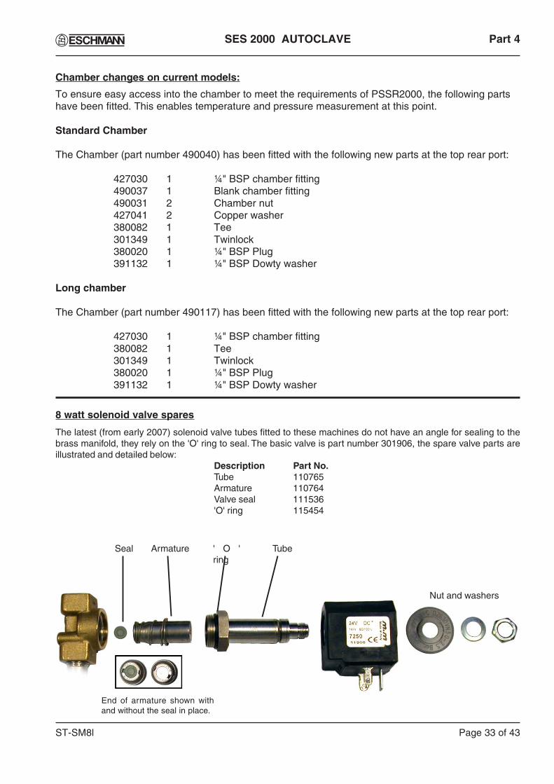
ST-SM8l Page 33 of 43
SES 2000 AUTOCLAVE Part 4
Chamber changes on current models:
To ensure easy access into the chamber to meet the requirements of PSSR2000, the following partshave been fitted. This enables temperature and pressure measurement at this point.
Standard Chamber
The Chamber (part number 490040) has been fitted with the following new parts at the top rear port:
427030 1 ¼" BSP chamber fitting490037 1 Blank chamber fitting490031 2 Chamber nut427041 2 Copper washer380082 1 Tee301349 1 Twinlock380020 1 ¼" BSP Plug391132 1 ¼" BSP Dowty washer
Long chamber
The Chamber (part number 490117) has been fitted with the following new parts at the top rear port:
427030 1 ¼" BSP chamber fitting380082 1 Tee301349 1 Twinlock380020 1 ¼" BSP Plug391132 1 ¼" BSP Dowty washer
8 watt solenoid valve spares
The latest (from early 2007) solenoid valve tubes fitted to these machines do not have an angle for sealing to thebrass manifold, they rely on the 'O' ring to seal. The basic valve is part number 301906, the spare valve parts areillustrated and detailed below:
Description Part No.Tube 110765Armature 110764Valve seal 111536'O' ring 115454
Armature TubeSeal
End of armature shown withand without the seal in place.
Nut and washers
' O 'ring

Page 34 of 43 ST-SM8l
Part 4 SES 2000 AUTOCLAVE
PART 4 ILLUSTRATED PARTS LIST 2: GENERAL SPARES
Fig. 10 General Spares

ST-SM8l Page 35 of 43
SES 2000 AUTOCLAVE Part 4
PART 4 ILLUSTRATED PARTS LIST 2: GENERAL SPARES
Fig. 10 Part No Description Qty.Per Recommended HoldingItem No Standard Long Unit Per Unit Per Year
1 490290 490142 Chassis 1 -2 490310 490144 Top cover 1 -3 111928 Screw, self tapping 4 44 490063 490146 Dividing panel 1 -5 490283 Front panel (without printer) 1 Not available for purchase6 490282 Front panel (with printer) 1 -7 - Pressure chamber assy. (See Parts List 1)8 490228 490178 Carrier assembly, tray 1 -9 - Tray (REF 87-040-07) 4 -10 490046 Reservoir (requires kit 112472) 1 -* 425170 . Surface tension breaker* 425062 . Reservoir lid rectangular (without switch hole)11 475872 . Reservoir aperture cover (round) 1 -12 425146 Ring, grey rubber 1 1* 425165 . Ring, adhesive - -13 425141 Ring seal, silicone 1 114 480301 Foot, c/w fixing screw 4 -* 380045 Spacer, foot 2 -15 490302 490304 Door cover assy. 1 -16 - Door assy. 1 -17 480315 . Door beam assy. 1 -18 490076 . Door knob 1 -19 427011 . Door secondary latch 1 -20* 427023 . Spring, secondary latch 1 -21 490017## . Door, pressure assy. 1 -22 424238## . Seal, retaining rim 1 -23 427037 . Door seal (gasket) 1 124 427015 . Retaining disc, seal 1 -25 427090 . Seal washer, steel 1 126 713651## . O-ring (on older models) 1 127# 307232# . Aerotight nut# 1 128 427010 Safety catch, door 1 -29* - Tray lifter (REF 87-040-90) 1 -30* 301409 Drip tray 1 -31* 425188 Accessory pack containing 1 -
4 off each, cups and spacers forcabinet feet
32* REF 87-040-66 Pouch rack accessory A/R -33 490291 Printer assembly 1 -34 490397 S.S.R.B.Insulation 1 -35 424395 Fuse cover 1 -36 424396 Water shield, control board 1 -37 427007 Door spindle assembly 1 -38 427008 Link 1 -* 380034 Cable saddles A/R -* 380033 Self mount cable ties A/R -* 301600 P.T.F.E.Tape A/R -* 306234 Hydraulic sealant A/R -
* Not illustrated # Now replaced by M6 Nut (710372) and M6 Spring washer (710721)## For units with an 'O' ring (before c.1999) replace parts 21, 22 and 26 withparts 21 and 22 only (latest design of these parts eliminates need for 'O' ring).

Page 36 of 43 ST-SM8l
Part 4 SES 2000 AUTOCLAVE
PART 4 ILLUSTRATED PARTS LIST 3: HEATER AND PROCESS CONTROLS
Fig. 11 Heater and Process Controls
Note: Items 9 and 9a arefitted to the underside ofchamber manifold butshown here for clarity.

ST-SM8l Page 37 of 43
SES 2000 AUTOCLAVE Part 4
PART 4 ILLUSTRATED PARTS LIST 3: HEATER AND PROCESS CONTROLS
Fig. 11 Part No Description Qty.Per Recommended HoldingItem No Standard Long Unit Per Unit Per Year
1 412012 Heating element 230V, 2kW - -416220 Heating element 230V, 2.75kW - -
412008 Heating element 110V, 1.4kW - -2 425114 Thermal fuse assy. 10A 1 1
(220V/240V units)380081 Thermal fuse assy. 20A 1 1
(110V units)380081 Thermal fuse assy. 20A 1 1
3 301162 Microswitch 1 14* 427021 Stop pin, microswitch 2 -5 480314 Sensor, water level assy. 1 -* 301806 . Shouldered washer 1 1* 301807 . Silicone bush 1 1* 425124 . Insulation bush 1 1* 425121 . Water level body 1 16 380026 Thermostat assy. 1 -7* 416149 Clamp, thermostat sensor bulb 1 -8 427020 Actuator arm, microswitch 1 -9 490260 Sensor, temperature, assy. 1 1
490260 Sensor, temperature, assy. 2 2(for units with printer)
9A 490262 Plate, retaining sensor 1 -10 301127 Lamp, neon, red (overheat) 1 -11 380000 Power switch, on/off 1 -12 490335 490338 Controller board assy. 1 -* 490336 . Daughter board 1 -* 301797 . Fuse F2A, 20 mm 1 1
* Not illustrated
Continued

Page 38 of 43 ST-SM8l
Part 4 SES 2000 AUTOCLAVE
Fig. 11 Part No Description Qty.per Recommended HoldingItem No Standard Long Unit Per Unit Per Year
13 110249 Transformer with shroud 1 -* 110250 . Transformer shroud 1 -14 301478 Solid state relay (not for CE Units**) 1 -14A 301481 Relay control board 1 -15* 696952 Varistor assy. 1 -16 380012 Terminal block 1 -17 380001 301890 Fuse holder, large 2 -18 301814 Fuse holder, small 1 -19* - Fuse: 2 2
Standard Long* 380003 301871 F10A 230/ 240V F15A 240V 2 1* 380002 301871 F13A 220V F15A 220V 2 1* 111940 F16A 110V 1 120* Fuse: 1 1* 696181 F400mA 220/230/240V 1 1* 380004 F800mA 110V 1 121 490080 Cable, power supply, assy. UK# 1 -
(inc. fused plug) (230V)22 710894 Clamp, cable 1 -23 710897 Nut, cable clamp 1 -24* 427022 Leafspring, microswitch actuator arm1 -25 427104 Lever assy. microswitch 1 126* 427020 Actuator arm, microswitch 1 -27 490337 Printer interface board 1 -29 490025 (CE ONLY**) Solenoid door lock 1 -30 427060 (CE ONLY**) Locking bolt 1 -31* 380072 (CE ONLY**) Ferrite clamp 3 1
mains loom32* 380073 (CE Printer version ONLY**) 1 1
Printer ribbon33* 490342 (CE ONLY**) E.M.I. Shield 1 -
* Not illustrated** See note below
PART 4 ILLUSTRATED PARTS LIST 3: HEATER AND PROCESS CONTROLS
# For other countries consult manufacturer.
IMPORTANT NOTE: From late 2008 all non-CE units are built as CE units (i.e. all units will bebuilt to the CE format). Comments qualified by 'non-CE units only' no longer apply and 'CEonly' will apply to all units.

SES 2000 AUTOCLAVE
Page 39 of 43
Printer Output
The printer output gives the following information:
♦ Manufacturer’s name Eschmann Equipment♦ Machine type SES 2000♦ Serial number Nine character code♦ Cycle type e.g. 134°C no drying♦ Time and date started At hh:mm:ss
On dd:mm:yy♦ Counter reading Five digits with leading
zeros♦ Time/temp information Time every 22 secs
(approx.) + temp. +graph of temperature.
♦ Cycle ended message♦ Time and date ended The ‘cycle end’ is
defined as the end ofthe sterilizing phase.
If an error occurs during the cycle, it is recorded withdate and time on the printout and the message‘CYCLE FAILED’. Errors are designated by errorcodes as follows:
ERR1 - Faulty temperature sensor/channeldetected
ERR2 - Door open during cycleERR3 - Chamber did not fill with water (LoH2O)ERR4 - Water loss early in cycle (H2O)ERR5 - No heatERR6 - Control temperature lowERR7 - Control temperature highERR8 - Monitor temperature lowERR9 - Monitor temperature high
These error codes will generally require investigationby an Eschmann trained engineer.
Front Panel Controls (Fig. A1)
All controls for the printer are on the front of the panel.a. Door Latch Button - To open door (1) push the
door latch (2) sideways, in the direction of arrow,and pull the door open to expose paper roll (4).
b. Paper Feed Button - Ensure the sterilizer mains‘on/off switch is in the ‘I’ (on) position. Presslower part of paper feed button (3) to activatepaper feed, which will continue for as long asthe button is depressed.
Paper Roll Renewal
CAUTION:DO NOT USE ALTERNATIVE PAPER ROLLS
The quality and size of paper rolls used in the printer,can only be supplied by Eschmann Equipment.
Renew paper roll as follows (Fig. A1 and A2):
a. Open autoclave chamber door to provide moreaccess.
b. Push door latch button (2) sideways, in direction ofarrow and pull door open to expose paper roll (4).
c. If any paper remains in the printer, tear end offagainst paper tear bar (8) and carefully withdrawthe remaining paper backwards from the rearof printer mechanism (5).
d. Compress paper roll spring-loaded retainerbutton (6) and withdraw empty paper spoolfrom spindle.
e. Take new roll of paper, separate paper endfrom the roll. Remove any damaged or gummedpart of the paper.
f. Compress paper roll spring-loaded retainerbutton (6) and locate new paper roll on spindlewith paper unreeling counter-clockwise as seenfrom open end of spindle (Fig. A1).
g. Using scissors, trim end of paper roll at anangle of approximately 30° (Fig. A4) and insertthis end of the paper into the paper insert slot(1). Press paper feed actuator arm (7) untilmechanism grips paper and pulls it through tofront of printer door.
h. Turn paper roll by hand to take up any slack paperi. Close the printer door. Check paper feed by
pressing paper feed button (3) until the end of thetrimmed paper is clear of the tear bar. Ensure thatthe paper feeds freely from the printer.
Ribbon Cartridge Renewal (Fig. A3 and A4)
Renew ribbon cartridge as follows:
a. Remove paper roll.b. Support door with left hand and press upwards with
right hand on bottom of printer mechanism chassis(Fig. A2-2) and separate chassis from door.
CAUTION:Do not pull printer mechanism chassis from
door until catch has been released.
c. Leaving printer door fully open, expose printermechanism and ribbon cartridge (Fig. A4-1).
d. Pinch the end of ribbon cartridge marked ‘PUSH’(Fig. A4-1) and remove cartridge.
e. Install new cartridge, checking that left hand sideof cartridge is correctly located on drive shaft,and CAREFULLY press cartridge into place.
f. Ensure ribbon is taut. If necessary tightenribbon by turning faceted disc (Fig. A2-2) oncartridge, clockwise, using finger or fingernail.
g. Fit paper roll as described above.
APPENDIX A - OPERATING INSTRUCTIONS FOR PRINTER
ST-SM8l
Appendix A

Appendix A SES 2000 AUTOCLAVE
Page 40 of 43 ST-SM8l
1
2
3
45
67
8
1. Printer Door 2. Door Latch 3. Paper Feed Button 4. Paper Roll
Fig. A1. Printer
1
2
1. Paper Insert Slot2. Printer Mechanism Chassis
Fig. A2. Paper Feed
Fig. A3. Ribbon Cartridge
Fig. A4. Ribbon Cartridge in Position
12
1. Ribbon Cartridge2. Faceted Disc
Fig. A5. Setting Date and time
switch 1
switch 2
switch 3
switch 4
134°C
134°C
121°C
121°CProgrammeswithout drying
Programmeswith drying
{{
Spares PackA spares pack is available comprising:
♦Five paper rolls♦Two ribbon cartridges
The spares pack is available from EschmannEquipment please quote REF 87-034-05.
Setting Date and Time (Fig. A5)1. To change the clock setting (e.g. from GMT to
BST or the reverse) proceed as follows: a. Select mains ‘on/off switch to ‘0’ (off). b. Push and hold switch 1 and switch 4 simultaneously
then select ‘on/off’ switch to ‘I’ (on). c. The display will read ‘01’. d. Then proceed as described in paragraph 2 (a) to (g).
2. To set the date and time proceed as follows: a. If closed, open chamber door. b. Display reads ‘01’. Push and hold switch 1. Observe
that number changes to 02,03 etc. through to 12.Also note that pushing and holding switch 2makes the number decrease. Use switch 1 andswitch 2 to set the number corresponding to themonth (01=January etc.). Push switch 3 to retainselection.
c. Display reads ‘dy01’. Again use switch 1 andswitch 2 to display the day of the month (pushswitch 3 to retain the day). Note: The computerwill prevent entry of dates such as 31st Nov.
d. Display reads ‘yr00’. Use switch 1 and switch 2to set any year from 00 to 99 (e.g. 97=1997).Then push switch 3 to retain it.
e. Display reads ‘hr00’. Use switch 1 and switch2 to set the hour - the system utilises a 24 hourclock. Then push switch 3 to retain it.
f. Display reads ‘in00’ (minutes). Use switch 1and switch 2 to show current minutes and pushswitch 3 to retain it.
g. The clock is now set.
5. Printer Mechanism6. Spring-Loaded Retainer
Button7. Paper Feed Actuator Arm8. Paper Tear Bar

APPENDIX B - Schematic diagram - Pipework and valves
CH
AM
BE
R
PR
ES
SU
RE
GA
UG
EP
RE
SS
UR
ED
OO
R L
OC
K
DOOR
AIR
VE
NT
DIS
CH
AR
GE
VA
LVE
PR
ES
SU
RE
RE
LIE
FV
ALV
E
RE
SE
RV
OIR
AIR
VE
NT
PIP
E
FIL
LV
ALV
E
DISCHARGEPIPE
DRAINHOSE TA
P
FILLPIPE
GA
UZ
E F
ILT
ER
FIL
TE
R B
LOC
K
MA
NIF
OLD
STA
ND
PIP
E C
ON
NE
CT
ION
FO
R F
ILL
AN
D D
ISC
HA
RG
E
CO
ND
EN
SO
R
NON-RETURNVALVE LS3
ONLY
TE
ST
PO
RT
S
TE
ST
PLU
G
SES 2000 AUTOCLAVE Appendix B
ST-SM8l Page 41 of 43


Eschmann Equipment, Peter Road, Lancing, West Sussex, BN15 8TJ, England.Tel: +44 (0) 1903 753322. Fax: +44 (0) 1903 875789. www.eschmann.co.uk

Appendix C SES 2000 AUTOCLAVE
APPENDIX C - Schematic diagram - CE version (see note page 38)
ST-SM8l Page 42 of 43
Link
BN
BE
Options chart
Transformer tappings
OE/BK
OE/BK
BE
STD2kW
LONG2.75kW
230V100KF400mAF10AF10A230V
230V100KF400mAF15AF15A230V
HeaterOverheat
neonR1F3F2
Wire colours
Abbreviation ColourBlackBrownRed
OrangeYellowGreen
Green/YellowBlue
MauveGreyWhitePink
Red/Black
BKBNRDOEYWGN
GN/YWBEMEGYWEPK
RD/BK
F3
BN
F1
F2
L
E
N
Mains input
0V
Mains on/off
BE
BE
BEBE
BE
Thermalfuse
Cycling thermostat
Variable capacitor
Heater
Fill valve
Dischargevalve
Solenoiddoor lock
Door switch
Central earth pointGN/YW
BN
BN
Mainstransformer
Printer Power PCA
490337
Printer
16 pinribbon cable
10 pinribbon cable
GYPK
WEME
OEGN
BKBK
Chamber sensor
Temperature sensorTemperature sensor
490335
PL2-10PL2-9PL2-8PL2-7PL2-6PL2-5PL2-4PL2-3PL2-2PL2-1
PL1-10PL1-9PL1-8PL1-7PL1-6PL1-5PL1-4PL1-3PL1-2PL1-1
RD
YW
GY
Relay board 301481
R1
Varistor
7
86 5
2 4 1 3
12
3 4
T1 T2 T3 T5 T6 T7T4
S.S.Relay
Voltagerating F1
(Optional)(Optional)
J6 DisplayJ5 Control
Daughter PCA
J3
J2
J1

Appendix C SES 2000 AUTOCLAVE
APPENDIX C - Schematic diagram - non-CE version (see note page 38)
Page 43 of 43 ST-SM8l
Link
BN
BE
Options chart
Transformer tappings
OE/BK
OE/BK
BE
STD2kW
LONG2.75kW
230V100KF400mAF10AF10A230V
230V100KF400mAF15AF15A230V
HeaterOverheat
neonR1F3F2
Wire colours
Abbreviation ColourBlackBrownRed
OrangeYellowGreen
Green/YellowBlue
MauveGreyWhitePink
Red/Black
BKBNRDOEYWGN
GN/YWBEMEGYWEPK
RD/BK
F3
BN
F1
F2
L
E
N
Mains input
0V
Mains on/off
BE
BE
BEBE
BE
Thermalfuse
Cycling thermostat
Variable capacitor
Heater
Fill valve
Dischargevalve
Door switch
Central earth pointGN/YW
BN
BN
Mainstransformer
Printer Power PCA
490337
Printer
16 pinribbon cable
10 pinribbon cable
GYPK
WEME
OEGN
BKBK
Chamber sensor
Temperature sensorTemperature sensor
490335
PL2-10PL2-9PL2-8PL2-7PL2-6PL2-5PL2-4PL2-3PL2-2PL2-1
PL1-10PL1-9PL1-8PL1-7PL1-6PL1-5PL1-4PL1-3PL1-2PL1-1
YW
Varistor
12
3 4S.S.Relay
Voltagerating F1
(Optional)(Optional)
J6 DisplayJ5 Control
Daughter PCA
J3
J2
J1