Embed Size (px)
Citation preview

STSM report COST FP1404
Cvetanka Chifliganec, from Ss. “Cyril and Methodius” University in Skopje, Faculty of
Civil Engineering – Skopje to ETH Zurich (6th to 18th of May 2018)
- The Purpose of this STSM was (1) to do a state-of-the-art on numerical modelling
of timber-concrete composite structures in fire and (2) to develop a new numerical
model of a TCC slab with screwed connection in fire in the computer program
SAFIR, which could calculate the slip between the subcomponents of the system.
- Short summary of performed STSM: The Host institution`s digital library was
used for collecting appropriate literature in the field of research. After performing
literature review, a state-of-the-art on numerical simulations of timber-concrete
composite structures exposed to fire was done. Visit to the laboratory at ETH
Zurich and attendance at one fire test was done. Also, visit to the Empa’s Fire
Technology Lab was done. A new numerical model for analysis of the TCC slab
with screwed connections in fire in the computer program SAFIR was developed.
- Description of the main results obtained: The state of the art showed that
numerical modelling is done only for small number of tested TCC slabs in fire. The
numerical model underestimated the fire resistance and the deflection of the TCC
structure. After several different parameters were varied in the developed model,
it was concluded that the response of the analysed TCC beam in fire was mainly
governed by the behaviour of the timber beam in fire and not the connections.
- Future collaboration with the host institution: No particular plans for future
collaborations are made for now.
- Foreseen publications/articles resulting from the STSM: The state of the art on
numerical modelling of TCC in fire and a step by step description of the modelling
procedure in the computer SAFIR are to be included in the guidance document
“Numerical modelling of timber-concrete composite structures in fire” prepared by
the WG2 TG2 of the COST action FP1404, which will form part of the background
documentation for the revision of EN 1995-1-2.
- Confirmation by the host institution of the successful execution of the STSM is
attached (Annex 1)

2
Annex 1 – Confirmation by Host Institution
3
Annex 2 – Scientific Report
Fire safety use of bio-based building products
Numerical modelling of timber-concrete
composite slabs exposed to fire
Scientific report of STSM at ETH Zurich
06.05-18.05.2018
Author:
Cvetanka Chifliganec,
Ss. “Cyril and Methodius” University in Skopje,
Faculty of Civil Engineering – Skopje
4
Table of Contents
Summary……………………………………………………………………………………...1
Annex 1………………………………………………………………………………………..2
Annex 2………………………………………………………………………………………..3
Table of Contents…………………………………………………………………………….4
1. Introduction ........................................................................................................ 5
2. Overview of performed work ............................................................................. 6
3. State of the art on numerical modelling of TCC in fire .................................... 8
3.1. TCC slab with screwed connections from Frangi [4] ..................................... 9
3.2. Description of the model TCC floor system from O`Neill at al. [8] .............. 11
3.3. Timber steel fibre–reinforced concrete floor slabs from Caldová et al. [12]..13
3.4. Timber steel fibre–reinforced concrete floor slabs from Blesák et al. [16]…15
3.5. Wood-concrete composite deck under fire conditions in Meena et al. [19] 17
4. Numerical model of the TCC slab in SAFIR ................................................... 19
4.1. Description of the model ................................................................................ 19
4.2. Material models…………………………………………………………………........23
4.3. Results from the numerical analysis and discussions ................................ 25
5. Conclusions………………………………………………………………..…………..27
References .............................................................................................................. 28

5
1. Introduction
Modelling the behaviour of timber-concrete composites (TCC) in fire is a very complex
process. Numerical models should provide a realistic analysis of structures exposed to
fire. They should be based on fundamental physical behaviour in such a way as to lead
to a reliable approximation of the expected behaviour of the relevant structural
component under fire conditions. They can be used for determination of: (1) charring
depth, (2) development and distribution of the temperature within structural members
(thermal response model), and (3) evaluation of the mechanical behaviour of the
structure or of any part of it (structural response model) [1].
In general, to describe the behaviour of a TCC structure in fire a nonlinear numerical
analysis has to be conducted. The nonlinearity of the problem comes from: the
changes in material properties by high temperatures (mechanical and thermal), the
nonlinear temperature distribution in the element`s cross-section and the continuous
change of internal forces in the structure. Also, as the structural behaviour of TCC is
mainly governed by the shear connection between the timber and the concrete, proper
simulation of the connector`s behaviour is of great importance for delivering accurate
results.
Nowadays, there are several computer programs capable of calculating the thermal
and mechanical behavior of TCC structures in fire. The validation of the advanced
numerical calculation models in these programs should be made based on comparison
with experimental results, analytical solutions or other computer codes. But, even
though an increased number of large-scale and small-scale testing of TCC structures
in fire are performed in recent years (see section state-of-the-art), numerical analyses
are conducted only for a small number of the them.
For the Expert Meeting of WG2 TG2 of COST Action FP1404, held in Skopje in October
2017, I presented one numerical model of a TCC slab in fire in SAFIR. Several
analyses of the TCC slab were conducted in order to compare the numerically
achieved results in SAFIR with the experimental data and the results obtained by the
simplified calculation method (based on the calculation model for mechanically jointed
beams with flexible elastic connections given in EN 1995-1-1 [2] and the reduced cross
6
section method given in EN 1995-1-2 [3]). In that model, the TCC slab was treated as
simply supported beam. Two different 2D models of the slab with different cross-
sections (T and TTTT) were made. The steel connectors were incorporated in the 2D
models, but the connection between the timber beam and the concrete slab could not
be treated as flexible and the slip between the subcomponents could not be calculated.
Since improvement of the numerical models was necessary, this STSM was the perfect
opportunity to do that at the institution where the fire tests of this particular TCC slab
were conducted. The aim of this STSM was to collect all necessary input data and to
conduct a numerical analysis of the TCC slab with screwed connection in fire tested
by Frangi et al [1] [4] [5]. The numerical analysis was conducted in the computer
program SAFIR, a special purpose computer program for the analysis of structures
under ambient and elevated temperature conditions, developed at the University of
Liège, Belgium by Jean-Marc Franssen and Thomas Gernay [6] [7].
2. Overview of performed work
During this STSM, a visit to the laboratory of the ETH Zürich, Institute of Structural
Engineering (IBK) was done. There, I was presented with: the testing instruments and
equipment, some previously tested specimens and elements, and the ongoing timber
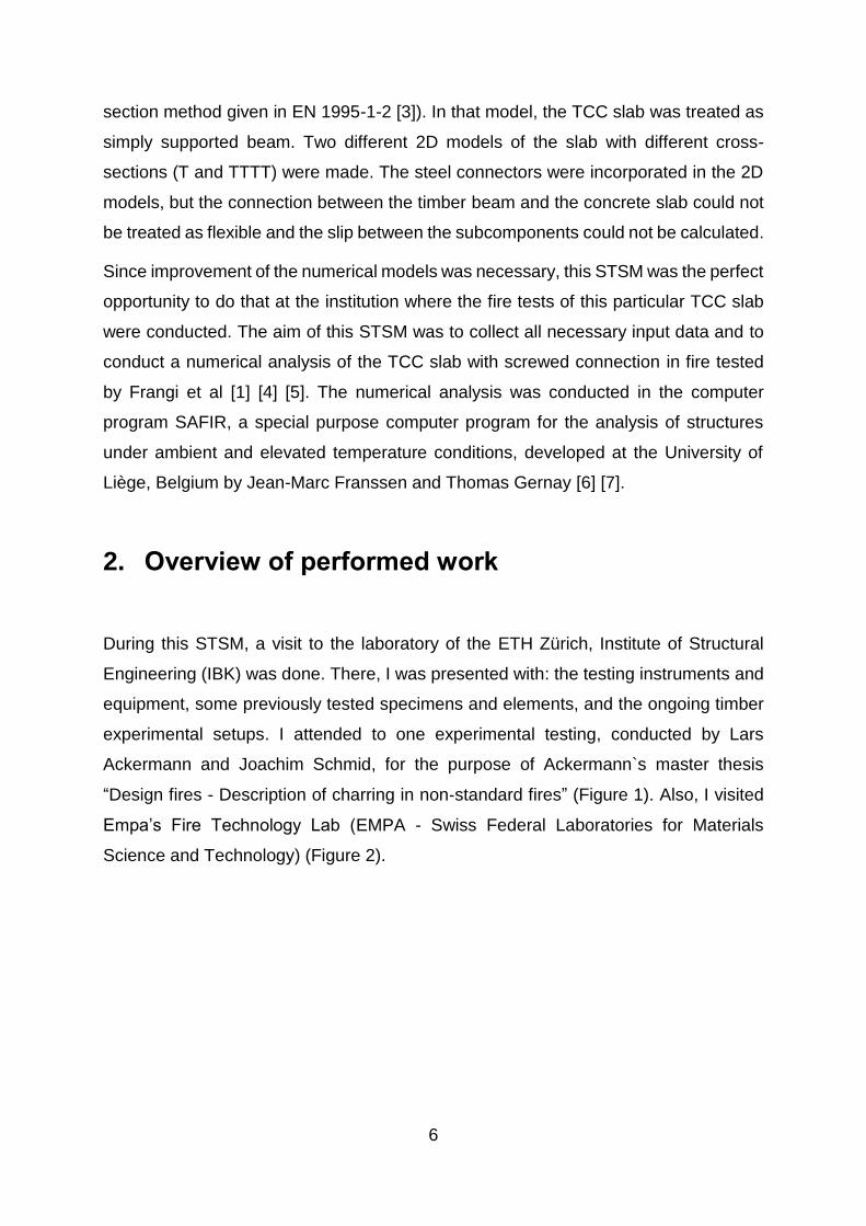
experimental setups. I attended to one experimental testing, conducted by Lars
Ackermann and Joachim Schmid, for the purpose of Ackermann`s master thesis
“Design fires - Description of charring in non‐standard fires” (Figure 1). Also, I visited
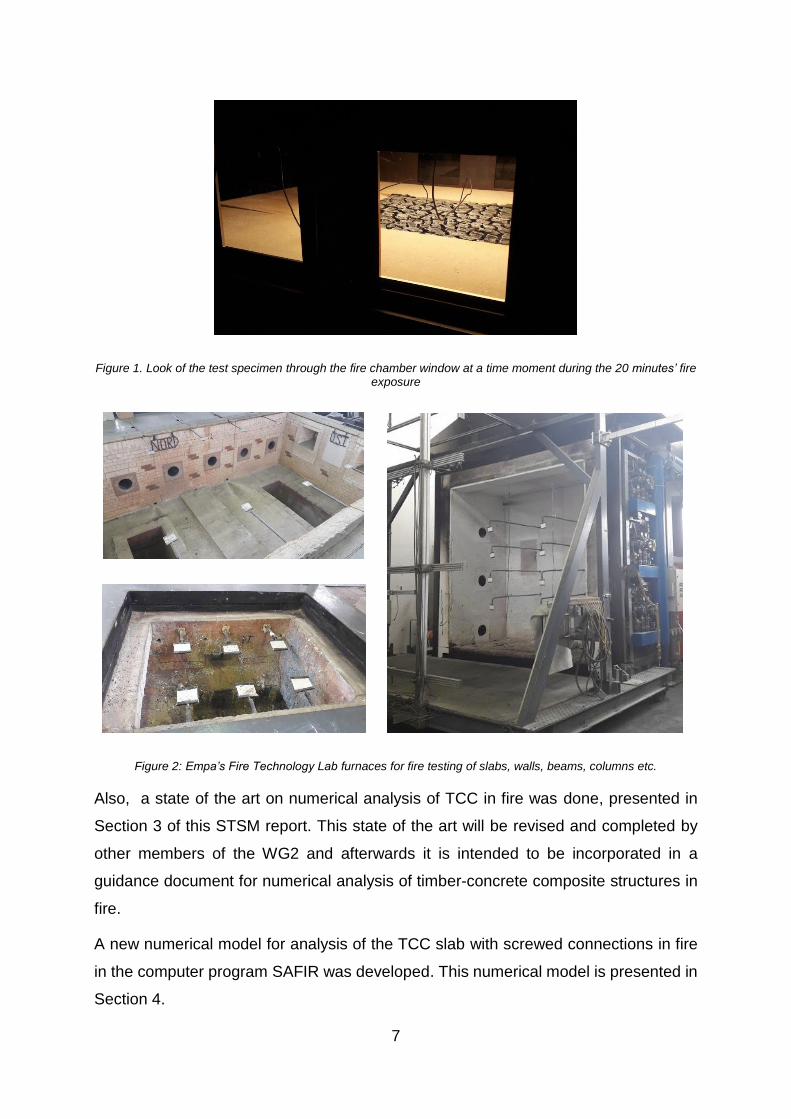
Empa’s Fire Technology Lab (EMPA - Swiss Federal Laboratories for Materials
Science and Technology) (Figure 2).
7
Figure 1. Look of the test specimen through the fire chamber window at a time moment during the 20 minutes’ fire exposure
Figure 2: Empa’s Fire Technology Lab furnaces for fire testing of slabs, walls, beams, columns etc.
Also, a state of the art on numerical analysis of TCC in fire was done, presented in
Section 3 of this STSM report. This state of the art will be revised and completed by
other members of the WG2 and afterwards it is intended to be incorporated in a
guidance document for numerical analysis of timber-concrete composite structures in
fire.
A new numerical model for analysis of the TCC slab with screwed connections in fire
in the computer program SAFIR was developed. This numerical model is presented in
Section 4.
8
3. State of the art on numerical modelling of TCC in
fire
Modelling of the behaviour of timber-concrete composites in fire is a very complex
process. Numerical models should provide a realistic analysis of structures exposed to
fire. They should be based on fundamental physical behaviour in such a way as to lead
to a reliable approximation of the expected behaviour of the relevant structural
component under fire conditions. The can be used for determination of: charring depth,
development and distribution of the temperature within structural members (thermal
response model), evaluation of structural behaviour of the structure or of any part of it
(structural response model) [3].
In general, to describe the behaviour of a TCC structure in fire nonlinear numerical
analysis has to be conducted. The nonlinearity of the problem comes from: the
changes in material properties by high temperatures (mechanical and thermal), the
nonlinear temperature distribution in the element cross-section and the continuous
change of internal forces in the structure. Also, as the structural behaviour of TCC is
mainly governed by the shear connection between the timber and the concrete, proper
simulation of the connector`s behaviour is of great importance for delivering accurate
results.
Nowadays there are several computer programs capable of calculating the thermal
and mechanical behavior of TCC structures in fire. Validation of the advanced
numerical calculation models in these programs should be made based on comparison
with experimental results, analytical solutions or other computer codes. But, even
though increased number of large-scale and small-scale testing of TCC structures in
fire are performed in recent years, numerical models are made only for a small number
of the tested TCC.
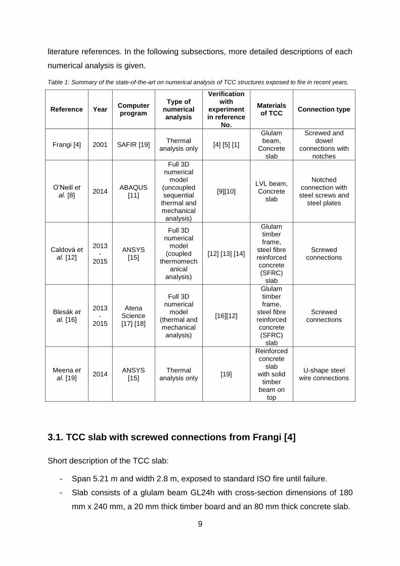
Table 1 presents a summary of the state-of-the-art on numerical modelling of TCC
structures exposed to standard fire in recent years. These numerical analyses were
performed for the purpose of delivering results for particular experimentally tested TCC
structures. The table lists: the types of TCC structures analyzed, the computer
programs used for numerical analysis, the research groups and the corresponding
9
literature references. In the following subsections, more detailed descriptions of each
numerical analysis is given.
Table 1: Summary of the state-of-the-art on numerical analysis of TCC structures exposed to fire in recent years.
Reference Year Computer program
Type of numerical analysis
Verification with
experiment in reference
No.
Materials of TCC
Connection type
Frangi [4] 2001 SAFIR [19] Thermal
analysis only [4] [5] [1]
Glulam beam,
Concrete slab
Screwed and dowel
connections with notches
O’Neill et al. [8]
2014 ABAQUS
[11]
Full 3D numerical
model (uncoupled sequential
thermal and mechanical analysis)
[9][10] LVL beam, Concrete
slab
Notched connection with steel screws and
steel plates
Caldová et al. [12]
2013-
2015
ANSYS [15]
Full 3D numerical
model (coupled
thermomechanical
analysis)
[12] [13] [14]
Glulam timber frame,
steel fibre reinforced concrete (SFRC)
slab
Screwed connections
Blesák et al. [16]
2013-
2015
Atena Science [17] [18]
Full 3D numerical
model (thermal and mechanical analysis)
[16][12]
Glulam timber frame,
steel fibre reinforced concrete (SFRC)
slab
Screwed connections
Meena et al. [19]
2014 ANSYS
[15] Thermal
analysis only [19]
Reinforced concrete
slab with solid
timber beam on
top
U-shape steel wire connections
3.1. TCC slab with screwed connections from Frangi [4]
Short description of the TCC slab:
- Span 5.21 m and width 2.8 m, exposed to standard ISO fire until failure.
- Slab consists of a glulam beam GL24h with cross-section dimensions of 180
mm x 240 mm, a 20 mm thick timber board and an 80 mm thick concrete slab.

10
- The screws in the connection have 45° of inclination. The distance between the
screws, with 100 mm of its length embedded in the timber and 50 mm in the
concrete, is 120 mm, and the side cover of the screws is 50 mm.
- The mechanical load is kept constant during the fire test and the slab is
designed to survive 60 minutes of fire exposure.
Figure 3: Cross section (left) and longitudinal section (right) of the timber-concrete composite slab tested by Frangi [4]
Several researchers did numerical analysis of the TCC slab with screwed connections
experimentally tested by Frangi [4].
In [4], a thermal numerical analysis of the timber sections was done, using the program
SAFIR. The results of the numerical analysis (the temperature fields) were in good
correlation with the experimental results.
In [20], the finite element program ANSYS [15] was used for a 3D sequentially coupled
thermal-mechanical analysis of the above mentioned TCC structure. The data for the
thermal and mechanical properties of concrete and timber were adopted from the
EN 1994-1-2 [21] and EN 1995-1-2 [3], respectively. First a thermal analysis was
conducted to determine the temperature field distribution of the TCC beam under fire.
The element type used in the thermal analysis was Solid 70. Boundary conditions on
the surfaces subjected to fire were set by radiation and convection according to the
ISO 834 standard fire curve. Then, the mechanical analysis of TCC beam was made
by importing the results of thermal analysis into the structural model. During the
mechanical analysis, the thermal element for timber and concrete was replaced by
Solid 185 and Solid 65, respectively. The shear connectors were set by the element
Combination 39. The results for the temperatures in the cross section and the
deflection of the structure were in good agreement with the experimental results from
[4], but this model did not calculate and comment the slip between the concrete slab
and the timber beam.
11
For the TCC structure with crewed connections from [4] the guidance document in
preparation will give an overview of the complete modelling process in several
computer programs: ABAQUS, ANSYS, SAFIR and one self-developed program by
Tomaž Hozjan.
3.2. Description of the model TCC floor system from O`Neill at al. [8]
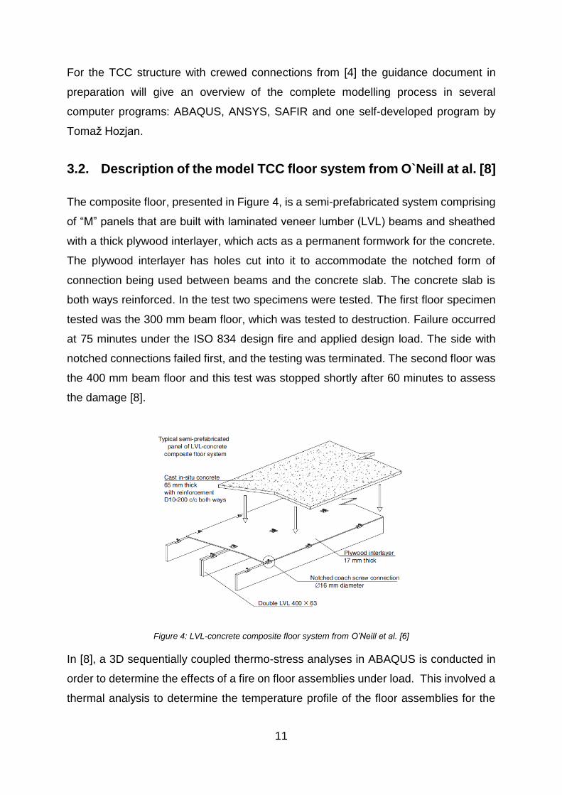
The composite floor, presented in Figure 4, is a semi-prefabricated system comprising
of “M” panels that are built with laminated veneer lumber (LVL) beams and sheathed
with a thick plywood interlayer, which acts as a permanent formwork for the concrete.
The plywood interlayer has holes cut into it to accommodate the notched form of
connection being used between beams and the concrete slab. The concrete slab is
both ways reinforced. In the test two specimens were tested. The first floor specimen
tested was the 300 mm beam floor, which was tested to destruction. Failure occurred
at 75 minutes under the ISO 834 design fire and applied design load. The side with
notched connections failed first, and the testing was terminated. The second floor was
the 400 mm beam floor and this test was stopped shortly after 60 minutes to assess
the damage [8].
Figure 4: LVL-concrete composite floor system from O’Neill et al. [6]
In [8], a 3D sequentially coupled thermo-stress analyses in ABAQUS is conducted in
order to determine the effects of a fire on floor assemblies under load. This involved a
thermal analysis to determine the temperature profile of the floor assemblies for the
12
duration of modelling, and then a stress analysis using the temperature profile as an
input into the structural model.
For the 3D thermal modelling of the floor, the temperature distribution in the cross
section was computed as an uncoupled heat transfer analysis using 8 node linear solid
elements, DC3D8.
The floor beams were subjected to 3 sided exposure to the ISO834 fire as a standard
temperature input into the models, and this is also applied to the underside surfaces of
the concrete floor slab. This was applied via surface film conditions and surface
radiation to the exposed surfaces, and ambient free convective surface conditions
were modelled on the top of the slab. The convection coefficient and emissivity were
assumed to be 25 W/m2K and 0.8, respectively. The cross section was discretized into
a 5 mm mesh, and along the length of the floor the mesh was left very coarse at
300 mm.
In the subsequent 3D structural modelling, the same mesh from the thermal analysis
was imported into the structural model (a cross sectional mesh size of 5 mm,
lengthwise of 300 mm), and the element type used was an 8 node 3D linear solid
element, C3D8R for both the timber and concrete portions of the floor. To consider
reduction in the mechanical properties of timber with temperature, the values for
reduction of the strength and modulus of elasticity were taken from the EN 1995-1-2
[3]. The timber is considered to behave in a brittle manner in tension, and to exhibit
elasto-plastic behaviour in compression. The material model being used to
characterize these stress-strain relationships for timber is the concrete damaged
plasticity model, which allows for separate stress strain curves to be defined for both
compression and tension. Plasticity is accounted for in the timber in compression via
specifying arbitrary values of plastic strain at the maximum compressive stress,
however in tension it is assumed to behave in a brittle manner and a strength reduction
of 99% is imposed once the maximum tension stress is reached. The values for the
thermal and mechanical properties of the concrete slab were taken from the
EN 1992-1-2.
The modelling of the floor structure was conducted in two phases. Firstly, the concrete
slab was left cold, and secondly it was heated. This was to define the influence of
heating the concrete slab on the behaviour of the floor as a whole.

13
For the 300 mm beam floor the failure was recorded at 75 minutes, and from the Figure
5a it can be seen that this is predicted well by the hot concrete model which specifies
a failure of approximately 74 minutes. For the 400 mm beam floor, the cold concrete
model predicted failure at approximately 85 minutes, while the hot concrete model is
slightly more conservative predicting failure at 81 minutes (Figure 5b). The
displacement response form the numerical analyses confirmed that the deeper joist
floor is much stiffer. From the analyses, it is found that the prediction of fire resistance
by displacement compares relatively well to the experimental results as long as the
thermal response of the concrete slab is incorporated.
Figure 5: Dispalcement reults for: a) 300 mm beam floor b)400 mm beam floor
3.3. Timber steel fibre–reinforced concrete floor slabs from
Caldová et al. [12]
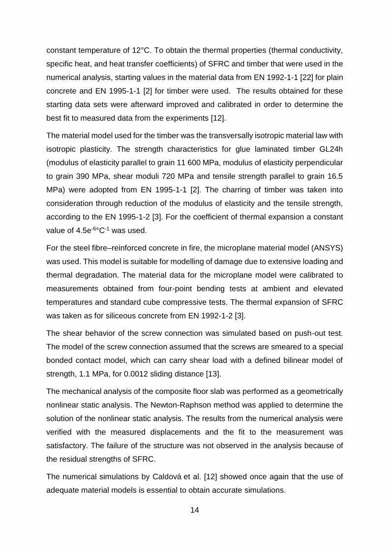
The experimentally tested and numerically analyzed composite timber fibre-reinforced
concrete floor by Caldová et al. [12], presented in Figure 6, is composed of timber
frame (glulam timber), two secondary beams (glulam timber), and a concrete slab
connected to floor joists. As connectors, screws inclined 45° to the beam axis in two
rows were used. The distance between the screws in one row was 0.1 m.
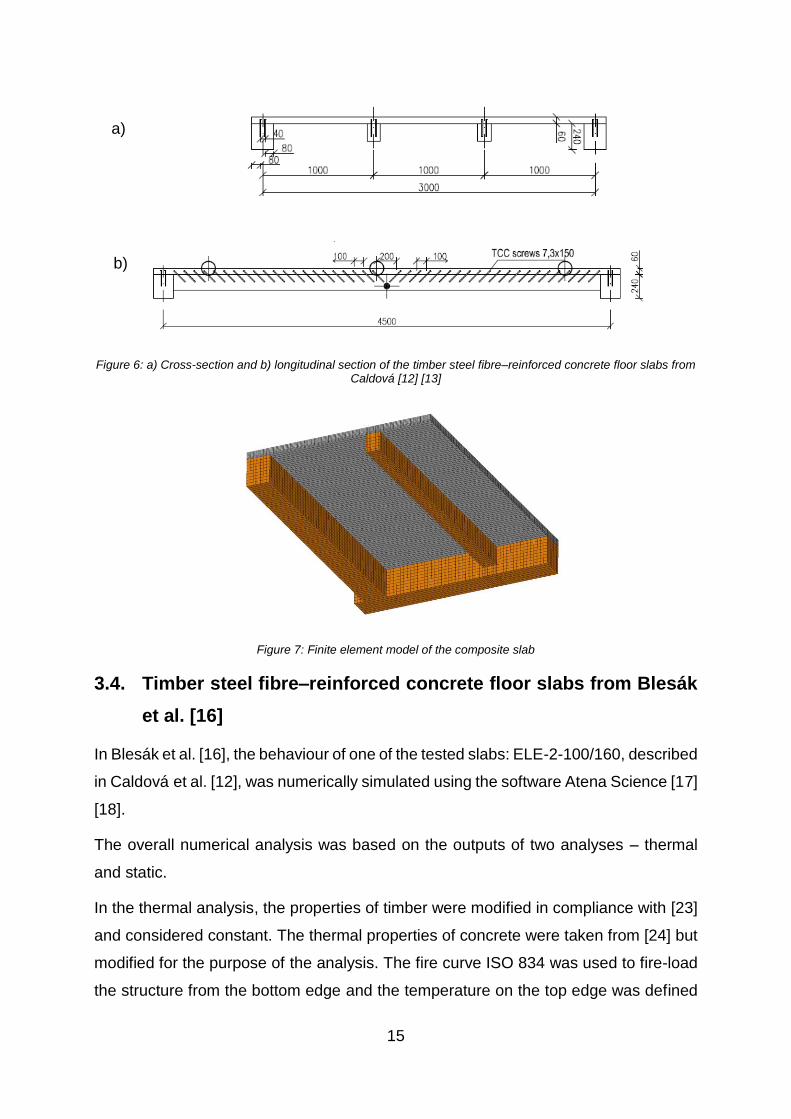
The 3D coupled thermo-mechanical numerical analysis was conducted in the FE
program ANSYS. The numerical model represented a symmetrical portion of the
structure and FE discretization with solids was used.
In the thermal analysis, the heat transfer in the structure was determined as a transient
nonlinear problem with an implicit Newmark’s integration. The boundary conditions on
the surfaces exposed to fire used radiation and convection based on measured furnace
temperatures from the experiments and the surfaces outside the furnace had a
a) b)
14
constant temperature of 12°C. To obtain the thermal properties (thermal conductivity,
specific heat, and heat transfer coefficients) of SFRC and timber that were used in the
numerical analysis, starting values in the material data from EN 1992-1-1 [22] for plain
concrete and EN 1995-1-1 [2] for timber were used. The results obtained for these
starting data sets were afterward improved and calibrated in order to determine the
best fit to measured data from the experiments [12].
The material model used for the timber was the transversally isotropic material law with
isotropic plasticity. The strength characteristics for glue laminated timber GL24h
(modulus of elasticity parallel to grain 11 600 MPa, modulus of elasticity perpendicular
to grain 390 MPa, shear moduli 720 MPa and tensile strength parallel to grain 16.5
MPa) were adopted from EN 1995-1-1 [2]. The charring of timber was taken into
consideration through reduction of the modulus of elasticity and the tensile strength,
according to the EN 1995-1-2 [3]. For the coefficient of thermal expansion a constant
value of 4.5e-6°C-1 was used.
For the steel fibre–reinforced concrete in fire, the microplane material model (ANSYS)
was used. This model is suitable for modelling of damage due to extensive loading and
thermal degradation. The material data for the microplane model were calibrated to
measurements obtained from four-point bending tests at ambient and elevated
temperatures and standard cube compressive tests. The thermal expansion of SFRC
was taken as for siliceous concrete from EN 1992-1-2 [3].
The shear behavior of the screw connection was simulated based on push-out test.
The model of the screw connection assumed that the screws are smeared to a special
bonded contact model, which can carry shear load with a defined bilinear model of
strength, 1.1 MPa, for 0.0012 sliding distance [13].
The mechanical analysis of the composite floor slab was performed as a geometrically
nonlinear static analysis. The Newton-Raphson method was applied to determine the
solution of the nonlinear static analysis. The results from the numerical analysis were
verified with the measured displacements and the fit to the measurement was
satisfactory. The failure of the structure was not observed in the analysis because of
the residual strengths of SFRC.
The numerical simulations by Caldová et al. [12] showed once again that the use of
adequate material models is essential to obtain accurate simulations.
15
Figure 6: a) Cross-section and b) longitudinal section of the timber steel fibre–reinforced concrete floor slabs from Caldová [12] [13]
Figure 7: Finite element model of the composite slab
3.4. Timber steel fibre–reinforced concrete floor slabs from Blesák
et al. [16]
In Blesák et al. [16], the behaviour of one of the tested slabs: ELE-2-100/160, described
in Caldová et al. [12], was numerically simulated using the software Atena Science [17]
[18].
The overall numerical analysis was based on the outputs of two analyses – thermal
and static.
In the thermal analysis, the properties of timber were modified in compliance with [23]
and considered constant. The thermal properties of concrete were taken from [24] but
modified for the purpose of the analysis. The fire curve ISO 834 was used to fire-load
the structure from the bottom edge and the temperature on the top edge was defined
a)
b)
16
to be 25°C, the same as the initial temperature of all the used materials. The convection
heat transfer coefficient was considered 50 W/(°C.m2), resulting emissivity factor of
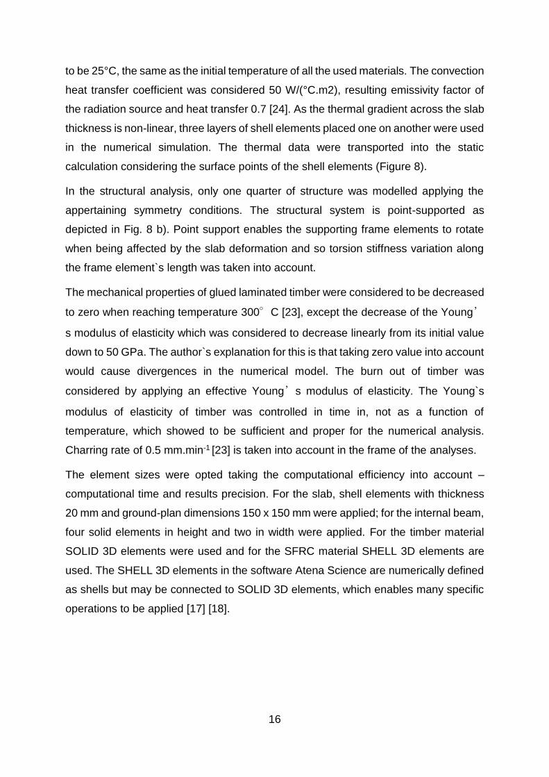
the radiation source and heat transfer 0.7 [24]. As the thermal gradient across the slab
thickness is non-linear, three layers of shell elements placed one on another were used
in the numerical simulation. The thermal data were transported into the static
calculation considering the surface points of the shell elements (Figure 8).
In the structural analysis, only one quarter of structure was modelled applying the
appertaining symmetry conditions. The structural system is point-supported as
depicted in Fig. 8 b). Point support enables the supporting frame elements to rotate
when being affected by the slab deformation and so torsion stiffness variation along
the frame element`s length was taken into account.
The mechanical properties of glued laminated timber were considered to be decreased
to zero when reaching temperature 300°C [23], except the decrease of the Young’
s modulus of elasticity which was considered to decrease linearly from its initial value
down to 50 GPa. The author`s explanation for this is that taking zero value into account
would cause divergences in the numerical model. The burn out of timber was
considered by applying an effective Young’s modulus of elasticity. The Young`s
modulus of elasticity of timber was controlled in time in, not as a function of
temperature, which showed to be sufficient and proper for the numerical analysis.
Charring rate of 0.5 mm.min-1 [23] is taken into account in the frame of the analyses.
The element sizes were opted taking the computational efficiency into account –
computational time and results precision. For the slab, shell elements with thickness
20 mm and ground-plan dimensions 150 x 150 mm were applied; for the internal beam,
four solid elements in height and two in width were applied. For the timber material
SOLID 3D elements were used and for the SFRC material SHELL 3D elements are
used. The SHELL 3D elements in the software Atena Science are numerically defined
as shells but may be connected to SOLID 3D elements, which enables many specific
operations to be applied [17] [18].
17
Figure 8: a) Thermal gradient pattern across the slab thickness in 60 min. – 1 x shell element vs. 3 x shell elements across the slab thickness. b) Scheme of the numerical model.
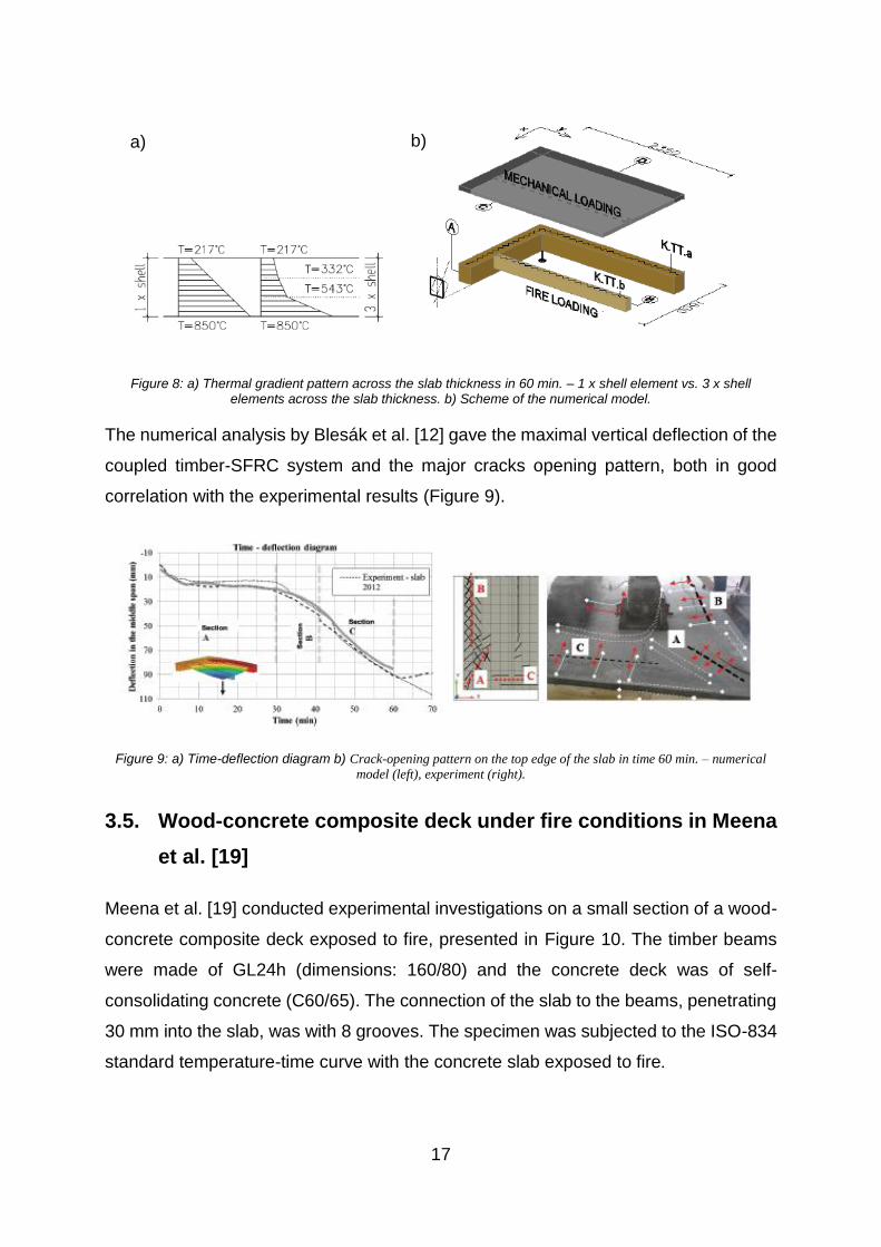
The numerical analysis by Blesák et al. [12] gave the maximal vertical deflection of the
coupled timber-SFRC system and the major cracks opening pattern, both in good
correlation with the experimental results (Figure 9).
Figure 9: a) Time-deflection diagram b) Crack-opening pattern on the top edge of the slab in time 60 min. – numerical
model (left), experiment (right).
3.5. Wood-concrete composite deck under fire conditions in Meena
et al. [19]
Meena et al. [19] conducted experimental investigations on a small section of a wood-
concrete composite deck exposed to fire, presented in Figure 10. The timber beams
were made of GL24h (dimensions: 160/80) and the concrete deck was of self-
consolidating concrete (C60/65). The connection of the slab to the beams, penetrating
30 mm into the slab, was with 8 grooves. The specimen was subjected to the ISO-834
standard temperature-time curve with the concrete slab exposed to fire.
a) b)

18
Figure 10:. The WCCD element (left) and the cross-section of the specimen (right, all dimensions in mm)
In order to obtain the temperature profiles in the materials of the specimen under fire
conditions, Meena et al. [16] conducted only thermal numerical analysis. For the
numerical analysis, the commercial software package Ansys Workbench v12 was
used. An isometric view of the model can be seen in Figure 11. Only a portion of the
test specimen was modelled, as the temperature variation across the bottom surface
of the system was determined to be nearly identical during the conducted fire tests.
Contact sizing, with element size 10 mm, was used to refine the mesh at the contact
surface of the timber beam and the concrete slab.
When describing the thermal properties of the materials the author just points that
thermal conductivity and specific heat of the different materials for the modelling
purpose are taken from the literature [25] and gives the data from Figure 12.
Figure 11: Isometric view of the numerical model and meshing
Figure 12: Properties for different material for thermal analysis that are taken in Meena et al. [16]

19
4. Numerical model of the TCC slab in SAFIR
4.1. Description of the model
The subject of analysis was the TCC slab with crewed connections in fire tested by
Frangi et al. [1] [4] [5]. The cross-section and the longitudinal section of the slab are
once again presented in Figure 13.
Figure 13: Cross section of the TCC beam
The nonlinear 2D numerical analyses were conducted with the computer programme
SAFIR specialized for structural fire analysis [6] [7]. The analysis of the structure
exposed to fire consist of two steps. The first step involves predicting the temperature
distribution inside the structural members, termed as ‘thermal analysis’. The second
part of the analysis, termed as ‘structural analysis’, is carried out for the main purpose
of determining the response of the structure due to static and thermal loading.
In the structural analysis, the TCC beam was treated as a simply supported Virendeel
truss. The top chords represent the concrete slab, the bottom chords represent the
timber beam and the verticals/webs represent the connections (Figure 14). The vertical
steel beam elements are placed at the exact position of the screws through the length
of the tested TCC beam.
Figure 14: Structural system of the modelled TCC slab and loads
The cross sections of the concrete slab, the timber beam and steel verticals are
presented in Figure 18a, Figure 19a and Figure 19b, respectively. The interlayer
between the concrete slab and the timber beam (timber board with thickness of 20
mm) was not modelled but it`s positive influence on the temperature profile in the
20
concrete slab was taken into consideration by assigning a temperature-time curve to
describe the evolution of temperature at the bottom side of the concrete slab.
The main goal in this numerical model was to properly model the connections.
According to Frangi [4], one pair of the 45˚ inclined screws has: characteristic load-
carrying capacity Fv,rk=12.6 kN and slip modulus Kser=18 kN/mm. According to ETA-
13/0699 [26], these screws have: Fv,rk=18.38 kN and Kser=17.21 kN/mm. In the
numerical model, the steel verticals representing the connections are modelled as steel
beam elements with the same load carrying capacity as the 45˚ inclined screws in
Frangi [4].
The model in the structural analysis consisted of 168 beam elements. In each time
step, SAFIR uses an iterative procedure to converge to the correct solution. A precision
value of 0.0001 and the modified Newton-Raphson convergence procedure were used
in the analyses. For solving the system of equations the method of Paradiso, based on
a space matrix solver, was used. In SAFIR there is no deflection criterion for defining
the failure point, therefore the calculation goes on until the failure of the whole structure
happens. Local failure of a structural member that does not endanger the safety of the
whole structure is handled by the means of the dynamic analysis [6].
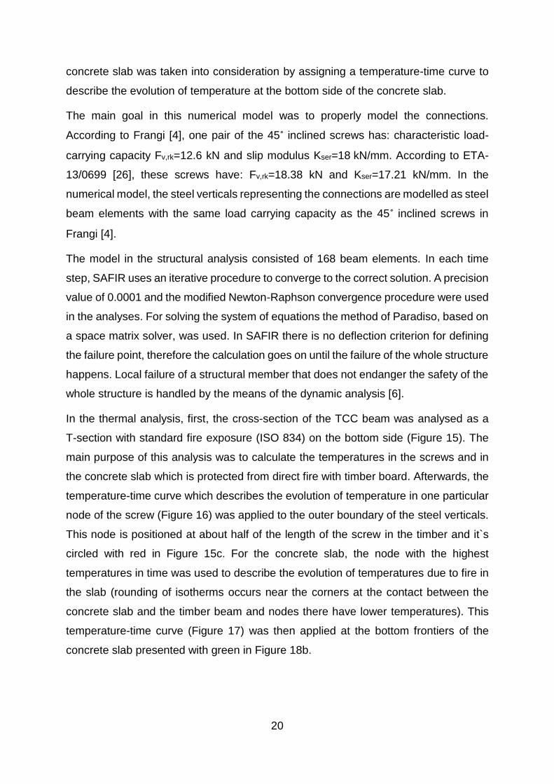
In the thermal analysis, first, the cross-section of the TCC beam was analysed as a
T-section with standard fire exposure (ISO 834) on the bottom side (Figure 15). The
main purpose of this analysis was to calculate the temperatures in the screws and in
the concrete slab which is protected from direct fire with timber board. Afterwards, the
temperature-time curve which describes the evolution of temperature in one particular
node of the screw (Figure 16) was applied to the outer boundary of the steel verticals.
This node is positioned at about half of the length of the screw in the timber and it`s
circled with red in Figure 15c. For the concrete slab, the node with the highest
temperatures in time was used to describe the evolution of temperatures due to fire in
the slab (rounding of isotherms occurs near the corners at the contact between the
concrete slab and the timber beam and nodes there have lower temperatures). This
temperature-time curve (Figure 17) was then applied at the bottom frontiers of the
concrete slab presented with green in Figure 18b.
21
Figure 15: a) Cross section of the TCC beam modeled as a T-section b) Temperature field in the cross-section at
the moment of failure of the structure (56 min) c) Temperature-time curves in some particular nodes along the
length of the screw in the timber
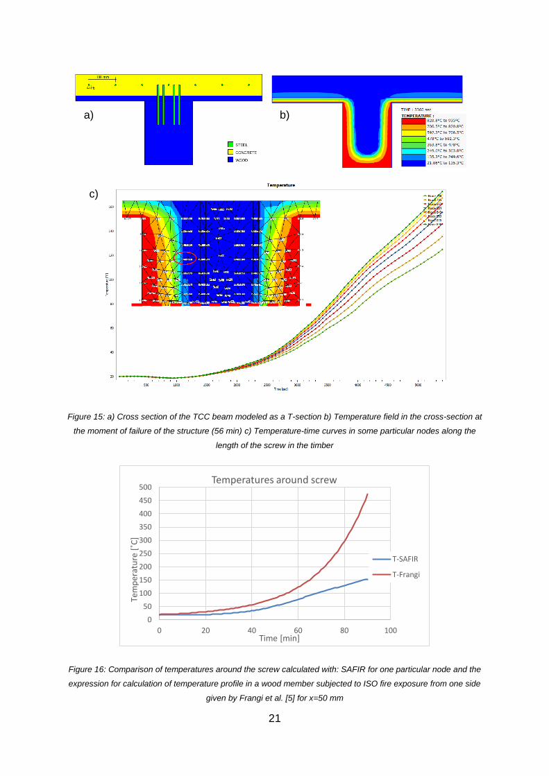
Figure 16: Comparison of temperatures around the screw calculated with: SAFIR for one particular node and the
expression for calculation of temperature profile in a wood member subjected to ISO fire exposure from one side
given by Frangi et al. [5] for x=50 mm
0
50
100
150
200
250
300
350
400
450
500
0 20 40 60 80 100
Tem
per
atu
re [
˚C]
Time [min]
Temperatures around screw
T-SAFIR
T-Frangi
a) b)
c)

22
Figure 17: -Temperature-time curve describing the evolution of temperature at the bottom side of the concrete
slab
Figure 18: a) Cross section of the TCC beam (dimensions in meters) b) Fire exposed surfaces c) Temperature
field at the time of failure (t=56 min) and applied mesh
-50
0
50
100
150
200
250
300
350
400
0 20 40 60 80 100
Tem
per
atu
re [
˚C]
Time [min]
Temperatures on the bottom side of the concrete slab
a)
b)
c)

23
Figure 19: Temperature field at the time of failure of the structure (t=56 min) and applied finite elements mesh a)
in the timber beam b) in the steel verticals
In the thermal analyse, SOLID elements were used to model the cross-sections. The
number of solid elements was: 1424 for the concrete slab (Figure 18c), 3884 for the
timber beam (Figure 19a) and 260 for the steel verticals (Figure 19b). After several
analyses were conducted, it was concluded that increasement of the solid elemnets i.e
decreasement of the mesh size in the cross-sections did not influenced the results of
the structural analysis.
4.2. Material models
For concrete, steel and wood, the thermal models are based on the corresponding
Eurocodes.
For concrete - SILCON ETC [27] , the material model is based on the laws of EN 1992-
1-2 [22] except that in the ETC model the transient creep strain treated by an explicit
term in the strain decomposition.
For structural carbon steel (used for the steel verticals), the material model, based on
EN 1993-1-2 [27], is elastoplastic with a limiting strain for yield strength of 0.15 and an
ultimate strain of 0.20.
For reinforcing carbon steel (used for the reinforcement in the concrete lab), the
material model is based on the EN 1992-1-2 [28].
a) b)
24
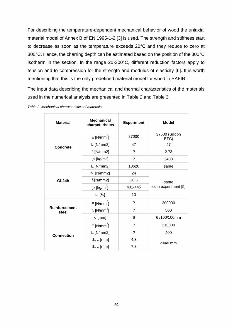
For describing the temperature-dependent mechanical behavior of wood the uniaxial
material model of Annex B of EN 1995-1-2 [3] is used. The strength and stiffness start
to decrease as soon as the temperature exceeds 20°C and they reduce to zero at
300°C. Hence, the charring depth can be estimated based on the position of the 300°C
isotherm in the section. In the range 20-300°C, different reduction factors apply to
tension and to compression for the strength and modulus of elasticity [6]. It is worth
mentioning that this is the only predefined material model for wood in SAFIR.
The input data describing the mechanical and thermal characteristics of the materials
used in the numerical analysis are presented in Table 2 and Table 3.
Table 2: Mechanical characteristics of materials
Material Mechanical
characteristics Experiment Model
Concrete
E [N/mm2] 37000
37600 (Silicon ETC)
fc [N/mm2] 47 47
ft [N/mm2] ? 2.73
ρ [kg/m3] ? 2400
GL24h
E [N/mm2] 10620 same
fc [N/mm2] 24
same as in experiment [5]
ft [N/mm2] 16.5
ρ [kg/m3] 431-445
ω [%] 13
Reinforcement steel
E [N/mm2] ? 200000
fy [N/mm2] ? 500
d [mm] 6 6 /100/100mm
Connection
E [N/mm2] ? 210000
fy [N/mm2] ? 400
dinner [mm] 4.3 d=40 mm
dinner [mm] 7.3

25
Table 3: Thermal characteristics of materials
Material T characteristics Model
Concrete
Convection coefficient on hot surfaces αhot [W/m2K] 25
Convection coefficient on cold surfaces αcold [W/m2K] 4
Emissivity ε 0.7
Steel
Convection coefficient on hot surfaces αhot [W/m2K] 25
Convection coefficient on cold surfaces αcold [W/m2K] 4
Emissivity ε 0.7
Timber
Convection coefficient on hot surfaces αhot [W/m2K] 25
Convection coefficient on cold surfaces αcold [W/m2K] 4
Emissivity ε 0.8
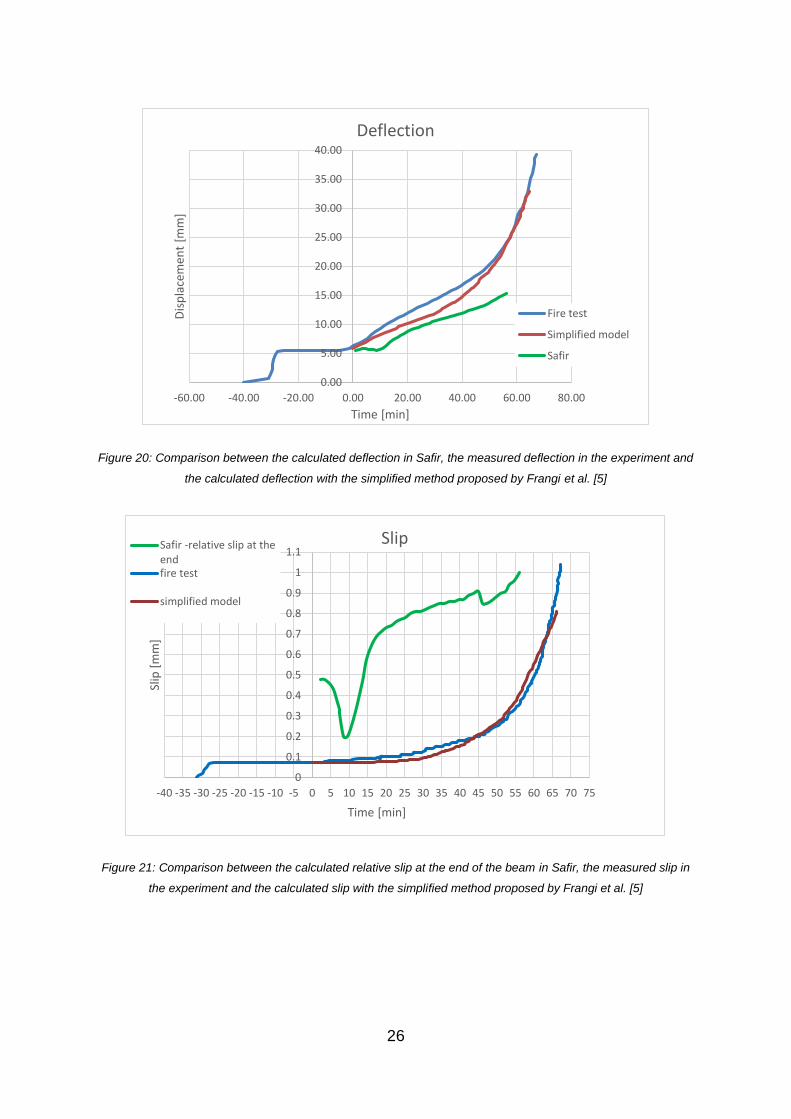
4.3. Results from the numerical analysis and discussions
This new numerical model for the TCC slab in fire was able to calculated the slip
between the subcomponents of the composite (concrete and timber), but it
overestimated its value. Also, the model in SAFIR underestimated the fire resistance
and the deflection of the TCC slab.
The main results from the analysis are presented in Table 4. Comparison of deflection
curves and slip curves between the numerical model and the experiment are presented
in Figure 20 and Figure 21, respectively.
Table 4: Results from the numerical analysis
Results from numerical
analysis
Fire resistance [min] 56.12
Deflection at failure [mm] 15.4
Slip at failure [mm] 0.537
26
Figure 20: Comparison between the calculated deflection in Safir, the measured deflection in the experiment and
the calculated deflection with the simplified method proposed by Frangi et al. [5]
Figure 21: Comparison between the calculated relative slip at the end of the beam in Safir, the measured slip in
the experiment and the calculated slip with the simplified method proposed by Frangi et al. [5]
0.00
5.00
10.00
15.00
20.00
25.00
30.00
35.00
40.00
-60.00 -40.00 -20.00 0.00 20.00 40.00 60.00 80.00
Dis
pla
cem
ent
[mm
]
Time [min]
Deflection
Fire test
Simplified model
Safir
0
0.1
0.2
0.3
0.4
0.5
0.6
0.7
0.8
0.9
1
1.1
-40 -35 -30 -25 -20 -15 -10 -5 0 5 10 15 20 25 30 35 40 45 50 55 60 65 70 75
Slip
[m
m]
Time [min]
SlipSafir -relative slip at theendfire test
simplified model
27
Several attempts were made to improve the results of the numerical analysis.
First the varying parameter was the mesh size. It was concluded that the mesh size
neither of the cross sections in the thermal analysis, nor of the structure in the structural
analysis had an effect on the results.
In order to see if the stiffness of the steel verticals in the truss have an influence on the
results, another parametric study was conducted. It was concluded that increasement
of the diameter of the steel vertical above 40 mm just decreased the initial deflection,
off course, but did not change the calculated fire resistance of the TCC beam.
5. Conclusions
The state of the art on numerical modelling of timber-concrete composite structure in
fire showed that numerical modelling is done only for few experimentally tested TCC
slabs in fire. This points out the need for more extensive research in this field.
A new numerical model for analysis of timber-concrete composite beam in fire was
developed in SAFIR, but it underestimated the fire resistance and the deflection of the
TSS structure and overestimated the relative slip at the end of the beam. After several
different parameters were varied in the model, it was concluded that the response of
the analysed TCC beam in fire was mainly governed by the behaviour of the timber
beam in fire and not the connections. One possible explanation for the lower fire
resistance of the model in comparison to the experiment could be that SAFIR uses the
constitutive model for wood according to EN 1995-1-2, where linear stress-strain
relations until failure for compression and tension are assumed. This has yet to be
verified.
Improvement of the numerical model is already in progress.

28
References
[1] Frangi, M. Fontana, Experimental tests on timber-concrete composite slabs at
room temperature and under ISO-fire exposure, Rep. No. 249, Institute of
Structural Engineering, ETH Zurich, Switzerland, 2000 (in German).
[2] CEN (European Commitee for Standardization), EN 1995-1-1: Eurocode 5 –
Design of timber structures - Part 1-1, 2004.
[3] CEN (European Commitee for Standardization), EN 1995-1-2: Eurocode 5 –
Design of timber structures - Part 1-2, 2004.
[4] Frangi, Brandverhalten von Holz-Beton-Verbunddecken, PhD thesis no 14328,
Institute of Structural Engineering, ETH Zurich, Switzerland, 2001 (in German).
[5] Frangi, M. Knobloch, M. Fontana, Fire design of timber-concrete composite
slabs with screwed connections, ASCE Journal of Structural Engineering 136
(2) (2010) 219–228.
[6] SAFIR University of Liège, Liège, Belgium, 2014
[7] J. Franssen, SAFIR : A Thermal/Structural Program for Modeling Structures
Under Fire, AISC Eng. J. (2005) 143–158.
[8] J. W. O’Neill, A.K. Abu, D.M. Carradine, P.J. Moss, A.H. Buchanan, Modelling
The Fire Performance of Structural Timber-Concrete Composite Floors, Journal
of Structural Fire Engineering 5 (2) (2014) 113–123.
[9] W. O’Neill, The Fire Performance of Timber-Concrete Composite Floor, Master
thesis, University of Canterbury, Christchurch, New Zealand, 2009.
[10] J.W. O’Neill, D.M. Carradine, P.J. Moss, M. Fragiacomo, R. Dhakal, A.H.
Buchanan, Design of Timber-Concrete Composite Floors for Fire Resistance,
Journal of Structural Fire Engineering 2 (3) (2011) 231–242.
[11] ABAQUS version 6.10 Dassault Systèmes Simulia Corporation, Providence, RI,
USA, 2010.

29
[12] E. Caldová, P. Vymlátil, F. Wald, A. Kuklíková, Timber steel fiber–reinforced
concrete floor slabs in fire: Experimental and Numerical Modelling, J. Struct.
Eng. 141 (9) (2015) 1–14.
[13] E. Caldová, L. Blesák, F. Wald, M. Kloiber, S. Urushadze, Behaviour of timber
and steel fibre reinforced concrete composite constructions with screwed
connections, Wood Research 59 (4) (2014) 639–660.
[14] E. Caldová, F. Wald, A. Kuklíková, Fire test of timber-fibre concrete composite
floor, Application of Structural Fire Engineering, Prague, Czech Republic, 1–4,
2013.
[15] ANSYS [Computer software]. Pennsylvania, PA
[16] L. Blesák, E. Caldová, F. Wald, Unprotected timber-fibre reinforced concrete
slab in fire. Wood research 60 (4) (2015) 605–615.
[17] Červenka, V., Červenka, J., Janda, Z., Pryl, D., 2014a: ATENA program
documentation. Part 8. User’s manual for ATENA-GiD. Interface, Červenka
Consulting Ltd, 115 pp.7.
[18] Červenka, V., Jendele, L., Červenka, J., 2014b: ATENA program
documentation. Part 1. Theory. Červenka Consulting Ltd, 290 pp.
[19] R. Meena, M. Schollmayer, T. Tannert, Experimental and Numerical
Investigations of Fire Resistance of Novel Timber-Concrete-Composite Decks,
Journal of Performance of Constructed Facilities 28 (6), special issue:
Performance of Timber and Hybrid Structures (2014) 1–8.
[20] Hao Du, Xiamin Hu*, Bing Zhang, Yao Minli, Numerical simulation on behaviour
of timber-concrete composite beams in fire, IOP Conf. Ser.: Earth Environ. Sci.
81 012148.
[21] CEN (European Commitee for Standardization), EN 1994-1-2: Eurocode 5 –
Design of compoite steel and concrete tructures - Part 1-2, 2005.
[22] CEN (European Commitee for Standardization), EN 1992-1-1: Eurocode 2 –
Design of concrete structures - Part 1-1 2005.
[23] ČSN EN 1995-1-2, 2006: Design of timber structures – Part 1-2: General –
Structural fire design.
30
[24] Wald, F., Burgess, I., De La Quintana, J., Vila Real, P., 2005: Calculation of fire
resistance of building structures. Published by Czech Technical University in
Prague, ISBN 80-01-03157-8, 239 pp.
[25] C. Bailey: One Stop Shop in Structural Fire Engineering, University of
Manchester.
[26] EOTA (European Organization for Technical Approval), European Technical
Approval ETA-13/0699, June 2012-June 2018.
[27] CEN (European Commitee for Standardization), EN 1993-1-2: Eurocode 3 -
design of steel structures – Part 1–2 2005.
[28] CEN (European Commitee for Standardization), EN 1992-1-2: Eurocode 2 –
Design of concrete structures - Part 1-2 2005.
[29] T. Gernay, J-M Franssen, “A formulation of the Eurocode 2 concrete model at
elevated temperature that includes an explicit term for transient creep”, Fire
Safety Journal, 51, pp. 1-9, 2012.