Embed Size (px)
Citation preview

STS Transfer Operations Plan For compliance with MARPOL Annex I, Chapter 8
Revision 3
SHIP NAME: ***
IMO NUMBER: ***

i
Foreword
The sections in this template shaded yellow are for Guidance or description for the purpose of
preparation of the STS Plan only. The user is to delete the contents of these sections or may in their
place insert specific requirements that may pertain to the vessel for which the template is being
developed. Furthermore, words and sentences with yellow shading are to be deleted. The entire
document with or without shading is editable. The only linked fields are the contents of the footer and
other locations which indicate the vessel’s name and IMO number.
This document is a template to assist the shipowner/operator/designer in preparing ship-specific Ship-
to-Ship Transfer Operation Plan (STS plan), demonstrating compliance with the requirements of
MARPOL Annex I, Chapter 8: “Prevention of Pollution during Transfer of Oil Cargo between Oil
Tankers at Sea”, Regulations 40, 41 and 42.
Furthermore, this STS Plan template and format has been developed taking into account the guidance
contained in the best practice guidelines for STS operations as identified by the International Maritime
Organization (IMO) in the following two documents:
• © IMO’s “Manual on Oil Pollution, Section I, Prevention” as amended (IMO Manual), and
• © CDI/ICS/OCIMF/SIGTTO “Ship-to-Ship Transfer Guide for Petroleum, Chemicals and
Liquefied Gases”, 2013 (STS Guide).
Users should be aware that the contents are subject to revision and amendments from time to time, and
that partial extracts may be misleading. ABS cannot accept any responsibility for material that may be
incomplete or out of date or otherwise in error. In any case where a difference exists between a
reproduced version and IMO´s and/or the aforementioned STS Guide’s current, authentic text, the
current, authentic text will prevail
The images and the sections detailing the IMO’s Manual on Oil Pollution and those from the
CDI/ICS/OCIMF/SIGTTO “Ship-to-Ship Transfer Guide for Petroleum, Chemicals and Liquefied
Gases”, 2013 (STS Guide) are copyright presentations. These may only be used specifically and only in
this ABS STS Transfer Operation Plan Template by the user. The STS Plan must be approved by either
the relevant flag Administration for the vessel or by a classification society authorized by the vessel’s
flag Administration for MARPOL Annex I certification. As ABS is authorized by more than 100
Countries for MARPOL Annex I certification, the completed template should be submitted to an ABS
Engineering Office for review.
Disclaimer
This document has been developed solely as guidance for the shipowner/operator/designer preparing
a Ship-to-Ship Transfer Operation Plan (STS plan) as required by the relevant sections of MARPOL
Annex I. Users should refer to the applicable sections of MARPOL as necessary. Users are also urged to
consult with their local ABS engineering office should more detailed interpretations be required. Any
variation between applicable regulations and the information provided in this document is
unintentional, and, in the case of such variations, the requirements of the regulations govern. This
guidance does not constitute advice by ABS and may not be relied upon to create a contractual right or
benefit enforceable by any person.

STS TRANSFER OPERATIONS PLAN SHIP NAME: ***
II IMO NUMBER: ***
Preparation of the STS Plan
Hint:
Turn on the “Show bookmarks” option: Click “File” tab, then “Options”, then “Advanced”, go to the
“Show document content” section, and check “Show bookmarks” checkbox.
On the cover page of the STS plan
1) Insert the ship’s name and IMO number. Make sure that the modifications are within the bookmark
brackets shaded in yellow.
2) Click “File” tab, then “Print” (without printing), then go back to the main document to continue
editing. Then all the occurrences of ship name and IMO number will be updated.
3) All the subsequent pages where the ship’s name and IMO number are required will be automatically
filled in.
4) On completion change the yellow shading to “No Color”
Part A, Section 1 is to include all ship specific details and the Appendices any other STS transfer
operation related documentation with supplementary information concerning good practices, liabilities,
vessels specific and relevant equipment. Similarly Part B Appendix I is to include vessel specific plans
and procedures.
It is imperative that the user of this template tailors its contents to comply with the Flag the vessel flies
in addition to the required compliance measures set forth in:
MARPOL Annex I, Chapter 8: “Prevention of Pollution during Transfer of Oil Cargo between Oil Tankers at Sea”, Regulations 40, 41 and 42.
IMO “Manual on Oil Pollution, Section I-Prevention” 2011,
and the guidance detailed in the
CDI/ICS/OCIMF/SIGTTO “Ship-to-Ship Transfer Guide for Petroleum, Chemicals and Liquefied Gases’, 2013 (STS Guide).
“Flag Administrations may have additional requirements for the STS Plan. Please consult with the local ABS Engineering Office”.
Deviation of STS Plans from Established Guidelines
This STS plan template includes the latest guidelines. A vessel’s STS plan should not deviate from these
guidelines in principle.
However, additional policies and procedures and instructions that are in line with these guidelines are
expected to and may be inserted where appropriate. The checklist in the appendices of this document
may be supplemented in addition with ship specific checklist that may be required to address
particular items that have not been considered by the sample checklist. Supplemental Checklist to not
require approval. Additions to the contents of the included Checklist may be permissible but not
deletions.

iii

STS TRANSFER OPERATIONS PLAN SHIP NAME: ***
IV IMO NUMBER: ***
Notes
Objectives of an STS Plan
• The STS plan being ship specific, includes all the necessary information and procedures that are
required for the safe execution of STS operations.
• The STS plan is a subset of the vessel’s Safety Management System (SMS). Therefore, the
objectives of the vessel’s ISM would also be applicable to the STS plan.
Renewal and Approval of an STS Plan
• When the vessel’s flag is changed, the STS plan is subject to be reapproved by the new flag
administration.
• If the company of a vessel changes, since the STS plan is part of the SMS, it is expected to reflect
the current tanker operator’s specific policies and procedures.
• Whenever a vessel is purchased second hand or a DOC management changes, a new and
updated STS plan is to be prepared and approved by the flag administration or its authorized
RO thereof.
• An exemption for the need for a re-approval could be considered for cases wherein, the flag of
the vessel does not change and the DOC of the handing over company is identical to the DOC
of the taking over company, both the companies having the same policies and procedures.
• An STS plan may require re-approval if the applicable guidelines change
In all the above situations confirmation from the tanker vessel’s Flag Administration is to be
obtained on the procedure the vessel’s shipowner intends to follow.
Service Provider’s Familiarity of the Vessel’s STS Plan
• As applicable and in association with the IMO Oil Pollution Manual / 6.2.1.2 the vessel’s
qualified POAC must have a thorough knowledge of the STS plan and it would be therefore
beneficial to submit the STS plan to the service provider prior to the preparation of the Joint
Plan of Operation.
Copies and Locations of a Vessel’s Approved STS Plan
• Copies of the STS plan should be available on the bridge, cargo control room and at the engine
control room. See Part A/Section 2/6.2.4.2.
• For the sake of consistency, amendments should be reflected in all three copies.

v
CONTENTS
PART A Operations, Process and Procedures ......................................... 1SECTION 1 Ship Particulars ...................................................................................... 2
1.1 List and Location of Ship’s Manuals and Plans ................................................. 3
1.2 Approval History ................................................................................................ 4
1.3 History of Revisions ........................................................................................... 5
1.4 Record of Crew Review ..................................................................................... 6
SECTION 2 Introduction ............................................................................................. 7
2.1 STS Transfer Operation Plan ............................................................................ 7
2.2 Regulatory Requirements .................................................................................. 8Regulation 40 ...................................................................................................................... 8Regulation 41 .................................................................................................................... 10Regulation 42 .................................................................................................................... 11
2.3 “Manual on Oil Pollution, Section I-Prevention” 2011 ...................................... 12
6.1 Introduction ........................................................................................................ 126.1.1 General provisions .............................................................................................. 126.1.2 Limitations of applicability .................................................................................... 126.1.3 Non-applicability to bunker operations ................................................................ 126.1.4 Exclusions due to emergencies ........................................................................... 126.1.5 Exclusions from Flag States ................................................................................ 12
6.2 General requirements for vessels involved in ship-to-ship transfer operations . 136.2.1 Person in overall advisory control ....................................................................... 136.2.2 STS transfer area ................................................................................................ 156.2.3 Notification to authorities ..................................................................................... 156.2.4 STS operations plan ............................................................................................ 166.2.5 Communications .................................................................................................. 176.2.6 Equipment ........................................................................................................... 196.2.7 Precautions against pollution .............................................................................. 216.2.8 State of readiness for an emergency .................................................................. 216.2.9 Contingency planning and emergency procedures ............................................. 21
6.3 Risk assessment ................................................................................................ 226.3.1 Risk assessment scope ....................................................................................... 22
6.4 Preparation for operations ................................................................................. 226.4.1 Preparations before manoeuvres ........................................................................ 226.4.2 Communications .................................................................................................. 23
STS TRANSFER OPERATIONS PLAN SHIP NAME: ***
VI IMO NUMBER: ***
6.4.3 Confirmation of readiness ................................................................................... 236.4.4 Joint Plan of Operation ........................................................................................ 246.4.5 Alignment of cargo manifolds .............................................................................. 246.4.6 Suspension of Hoses .......................................................................................... 256.4.7 Responsible person(s) requirements .................................................................. 256.4.8 Agreement between Vessels ............................................................................... 26
6.5 Performance of operations ................................................................................ 266.5.1 Immediate checks on start of operation .............................................................. 266.5.2 Confirmation of normality and permissibility to continue transfer ........................ 266.5.3 Periodical checks ................................................................................................ 266.5.4 Caution to avoid surge pressures ........................................................................ 276.5.5 Exchange of Information ..................................................................................... 276.5.6 Vapor Emission ................................................................................................... 276.5.7 Ballast Operations ............................................................................................... 276.5.8 Attention to mooring lines .................................................................................... 27
6.6 Completion of operations .................................................................................. 276.6.1 Adequate ullage space ........................................................................................ 276.6.2 Closure of valves and drainage of hoses ............................................................ 276.6.3 Coordination of unmooring plan .......................................................................... 286.6.4 Confirmation of items before unmooring ............................................................. 286.6.5 Completion of documentation & unmooring ........................................................ 28
6.7 Suspension of operations .................................................................................. 286.7.1 Examples of reasons for suspension of operations ............................................. 286.7.2 Resumption of operations ................................................................................... 29
6.8 References ........................................................................................................ 29
2.4 Arrangement of the STS Plan and Event Log .................................................. 30
SECTION 3 Definitions ............................................................................................. 31
SECTION 4 Foundation of an STS Plan .................................................................. 36
4.1 Preamble .......................................................................................................... 36
4.2 Scope ............................................................................................................... 36
4.3 Execution of Risk Assessments ....................................................................... 36
4.4 Centralized Control of Operations .................................................................... 36
4.4.1 General ............................................................................................................. 37
4.4.2 Adequate manning and prevention of fatigue during STS Operations .............. 38
4.5 Responsibility of STS Superintendent .............................................................. 38
4.6 Person in Overall Advisory Control (POAC) ..................................................... 40
4.7 Training and Familiarization of Ship’s Personnel ............................................. 40
4.7.1 General ............................................................................................................. 40
4.7.2 Components of Training .................................................................................... 40
4.8 Security of the Vessels Involved in the STS Transfer Operation ..................... 41

vii
4.9 Security associated with multiple Vessels ....................................................... 42
SECTION 5 Conditions and Requirements ............................................................ 43
5.1 Ship to Ship Compatibility ................................................................................ 43
5.2 Compatibility Assessment ............................................................................... 43
5.2.1 Vessels of Similar Lengths Involved in STS Transfer Operations ..................... 44
5.2.2 The use of Dumb Barges ................................................................................... 45
5.3 Notification to and Approval from the Authorities ............................................ 46
5.4 Transfer Area for STS Transfer Operations .................................................... 47
5.5 Environmental Conditions ................................................................................ 47
5.5.1 General conditions and measures ..................................................................... 47
5.5.2 Precautions and measures in cold weather conditions ...................................... 48
5.5.3 Ship to ship operations in ice conditions ............................................................ 49
5.5.4 Sloshing of cargo tanks ..................................................................................... 50
5.6 Ship to Ship Service Providers Quality Assurance (QA) requirements ........... 50
SECTION 6 STS Transfer Operations Safety ......................................................... 51
6.1 General Requirements .................................................................................... 51
6.2 Risk Assessment ............................................................................................. 51
6.2.1 Transfer Location Risk Assessment .................................................................. 51
6.2.2 Ship to Ship Transfer Operation Risk Assessment ............................................ 52
6.3 Life Saving Appliances (LSA) and Personal Protective Equipment (PPE) ...... 54
6.4 Checklists ........................................................................................................ 54
6.5 Material Safety Data Sheets (MSDS) .............................................................. 55
6.6 Considerations for the Accumulation of Gas on Open decks .......................... 55
6.7 Safety Infringement ......................................................................................... 55
6.8 Cargo Leakage ................................................................................................ 56
6.9 Helicopter Operations ...................................................................................... 56
6.10 Considerations of Safety during Cargo Transfer ............................................. 56
6.10.1 Naked Lights and Smoking ................................................................................ 56
6.10.2 Electrical Switchboards Earths .......................................................................... 57
6.10.3 Main Propulsion, Power Generation, Steering Gear and other Machinery ........ 57
6.10.4 Electrical Isolation .............................................................................................. 57
6.10.5 Use of Satellite Communication, Radar and Radio Equipment ......................... 58
6.10.6 Fire-fighting Equipment ...................................................................................... 59
6.10.7 Electrical storms ................................................................................................ 59
6.10.8 The use of galley Stoves ................................................................................... 59
6.10.9 Openings in the Accommodation ....................................................................... 59
6.10.10 Unauthorized craft ............................................................................................. 60
SECTION 7 STS Transfer Operations Communication ......................................... 61
7.1 General ............................................................................................................ 61
STS TRANSFER OPERATIONS PLAN SHIP NAME: ***
VIII IMO NUMBER: ***
7.2 Language of Operation ..................................................................................... 61
7.3 Communications before Arrival ........................................................................ 61
7.3.1 Information to be obtained from the Ships ........................................................ 61
7.3.2 Information to be given to the ship by the Organizer ........................................ 62
7.4 Navigational Warnings ..................................................................................... 62
7.5 Communications - Approach, Mooring and Unmooring ................................... 62
7.6 Cargo transfer operations Communications ..................................................... 63
7.7 Procedures to be Adopted for Communication failures .................................... 63
SECTION 8 STS Transfer Operational Preparations ............................................. 65
8.1 General ............................................................................................................. 65
8.2 The Joint Plan of Operation (JPO) ................................................................... 65
8.3 Preparation of STS Transfer Operation ............................................................ 66
8.4 Lightering Support Vessels .............................................................................. 67
8.5 Lights, Shapes and Sounds Navigational Signals ............................................ 68
SECTION 9 Maneuvering and Mooring ................................................................... 69
9.1 General ............................................................................................................. 69
9.2 Two STS Ships Under Power Maneuvering Alongside at Sea ......................... 69
9.2.1 Information to be obtained from the Ships ........................................................ 70
9.2.2 Guidance for Maneuvering Alongside ............................................................... 71
9.2.3 Guidance for Maneuvering a Two STS Ship Combination System to Anchorage72
9.2.4 Guidance for STS Transfers Underway ............................................................ 72
9.3 Manoeuvres with One Ship Already at Anchor ................................................. 73
9.4 In Port Operations Manoeuvres ....................................................................... 74
9.5 Maneuvering with One Ship Already Alongside a Terminal ............................. 74
9.6 Mooring Operations .......................................................................................... 74
9.6.1 Mooring Plans ................................................................................................... 74
9.6.2 Mooring Operations at Sea ............................................................................... 78
9.6.3 Mooring Operations in Port ............................................................................... 80
SECTION 10 STS Transfer Operation Procedures Alongside ................................ 82
10.1 Procedures Prior to Transfer ............................................................................ 82
10.2 Responsibility for STS Cargo Operations ......................................................... 82
10.3 Planning for Cargo Transfer ............................................................................. 82
10.4 General Guidance on the Transfer of Cargo .................................................... 84
10.5 Operational Guidance after Completion of Cargo Transfer .............................. 85
SECTION 11 STS Transfer Operation Unmooring ................................................... 86
11.1 Prior Unmooring Preparations .......................................................................... 86
11.2 Procedure for Unmooring ................................................................................. 86
11.2.1 Unmooring after Underway Transfer ................................................................. 86
11.2.2 Unmooring with one Ship at Anchor .................................................................. 87

ix
11.2.3 Unmooring from a Ship alongside a Terminal ................................................... 87
11.2.4 Unmooring with the use of Quick Release Arrangements ................................. 88
SECTION 12 STS Transfer Operation Equipment .................................................... 90
12.1 Fenders ........................................................................................................... 90
12.1.1 Fenders Associated with at Sea Transfer Operations ....................................... 90
12.1.2 Other Considerations Associated with Fenders for at Sea Transfer Operations92
12.1.3 Guidance for Fender Selection for at Sea Transfers ......................................... 93
12.1.4 Requirements for Fenders ................................................................................. 93
12.1.5 Fenders Associated with at Port Transfer Operations ....................................... 94
12.1.6 Low Pressure Fenders ....................................................................................... 95
12.1.7 Ribbed Fenders ................................................................................................. 95
12.1.8 Foam Filled Fenders .......................................................................................... 96
12.2 Cargo Transfer Hoses ..................................................................................... 96
12.2.1 Standards for Hoses .......................................................................................... 96
12.2.2 Length of Hoses ................................................................................................. 97
12.2.3 Flow Velocities and Pressure Ratings of Hoses ................................................ 97
12.2.4 Hose Handling ................................................................................................... 98
12.2.5 Connection of Hoses ......................................................................................... 98
12.2.6 Inspection of Hoses and Testing ....................................................................... 99
12.2.7 Marking .............................................................................................................. 99
12.3 Equipment for Mooring .................................................................................. 100
12.4 Transfer of Personnel – STS transfer Operations at Sea .............................. 102
12.4.1 Lifting Equipment Suitability ............................................................................. 103
12.5 Transfer of Personnel – STS transfer Operations in Port .............................. 105
12.6 STS transfer Operations Lighting .................................................................. 105
12.7 STS transfer Operations Ancillary Equipment ............................................... 105
12.8 STS transfer Operations Noise Levels .......................................................... 105
SECTION 13 STS Transfer Operation Emergencies .............................................. 107
13.1 Emergency Response Procedures & Contingency Planning ........................ 107
13.2 STS Transfer Operations Emergency Signals ............................................... 108
13.3 STS Transfer Operations Emergency Situations ........................................... 109
13.4 STS Transfer Operations Examples of Emergency Situations ...................... 109
13.5 Shipboard Marine Pollution Emergency Plan ................................................ 110
13.6 STS Ships State of Readiness for Emergencies ........................................... 110
13.7 STS Transfer Operations suspension as a Precautionary Step .................... 111
SECTION 14 References .......................................................................................... 112
PART B Appendices ................................................................................ 113Appendix A At Sea Ship to Ship Transfer Operations ......................................... 114
Check List 1 Prior Fixture .......................................................................................... 115

STS TRANSFER OPERATIONS PLAN SHIP NAME: ***
X IMO NUMBER: ***
Check List 2 Before Operations Commence .............................................................. 116
Check List 3 Before Run-In and Mooring ................................................................... 117
Check List 4 Before Cargo Transfer Commences ...................................................... 118
Check List 5 Before Unmooring .................................................................................. 119
Appendix B At Port Ship to Ship Transfer Operations ........................................ 120
Check List 6 Pre-Transfer In Port STS Cargo Transfer Check List ............................ 121
Check List 6A ISGOTT Ship/Shore Safety Check List .................................................. 123
Check List 7 Pre- STS Cargo Transfer Checks in Port .............................................. 127
Appendix C Personnel Transfers by Crane Checklist .......................................... 128
Check List 8 Personnel Transfers by Crane ............................................................... 129
Appendix D STS Transfers Involving Vapor Balancing ....................................... 132
Check List 9 STS Transfers Involving Vapor Balancing ............................................. 133
Appendix E STS Transfers Reverse Lightering Consideration ........................... 134
1 Reverse Lightering Operations Considerations .............................................. 134
1.1 General Concept ............................................................................................. 134
1.2 Fendering Considerations ............................................................................... 134
Appendix F STS Transfers Assembly of Hose Lengths ...................................... 136
1 Guidance on the Assembly of Hose Lengths ................................................. 136
1.1 General Concept ............................................................................................. 136
1.2 Lengths of Hose not Within the Containment Area ......................................... 136
1.3 Miscellaneous requirements for Hose Connections ........................................ 136
1.4 Preparatory measures for Hose Connections ................................................. 136
1.5 Tightening of Flanges for Hose Connections .................................................. 136
Appendix G STS Transfers Guidance on Risk Assessments .............................. 139
G1 High Level Risk Examples .............................................................................. 140
G2 Casual Factors Leading to High Level Risks .................................................. 141
G3 Risk Mitigation Measures Examples .............................................................. 142
Appendix H Fender Selection Assistance Request Form .................................... 143
Appendix I Ship Specific Plans ............................................................................. 145
1.0 General Arrangement ..................................................................................... 146
1.1 Tank Capacity Plan ........................................................................................ 147
1.2 Manifold and Drip Tray Arrangement and Details .......................................... 150
1.3 Anchor Handling and Mooring Arrangement .................................................. 151
1.3.1 Plan of Mooring Equipment on the Forecastle Deck ....................................... 151
1.3.2 Plan of Mooring Equipment Mid. Upper Deck ................................................. 153
1.3.3 Plan of Mooring Equipment AFT. Upper Deck ................................................ 153
1.4 List of Personnel, Location Responsibilities, Emergencies ............................ 154
1.5 Ship Interest Contacts .................................................................................... 155
Appendix J List of National Operational Contact Points .................................... 156

xi
PART C Event Log of STS Transfer Operation ..................................... 161SECTION 1 Record of STS Transfer Operations ................................................. 161
1.1 STS Transfer Operation Log ......................................................................... 162
1.2 STS Transfer Operations Detailed Log ......................................................... 163

STS TRANSFER OPERATIONS PLAN SHIP NAME: *** IMO NUMBER: *** 1
PART A Operations, Process and Procedures
Page left intentionally blank
PART A Operations, Process and Procedures SECTION 1 Ship Particulars
STS TRANSFER OPERATIONS PLAN SHIP NAME: ***
2 IMO NUMBER: ***
SECTION 1 Ship Particulars
[The following items are to be ship specific]
Table 1
No. Item 1 Ship Name: *** 2 ABSID: *** 3 ABS Class Notations: *** 4 Flag: *** 5 Port of Registry: *** 6 Gross Tonnage: *** 7 Dead Weight: *** 8 Service Speed: *** 9 Registration Number: IMO number and/or other registration numbers, if
applicable 10 Regulation Length: *** 11 Length Overall: *** 12 Length Between Perpendiculars: *** 13 Beam: *** 14 Design Draft: *** 15 Draft Forward: *** 16 Draft Aft: *** 17 Maximum Manifold Height Above Waterline (m): *** 18 Liquid Manifold (Size / Number): *** 19 Vapor Manifold (Size / Number): *** 20 Manifold Dimensions: *** 21 Bow to Center Manifold: *** 22 Deck Crane Certified for Personnel Lifting: *** 23 Ship Type: *** 24 International Call Sign and Maritime Mobile Service Identity (MMSI): *** 25 Vessel enrolled in ABS Rapid Response Damage Assessment (RRDA)
Program, administered from the ABS Headquarters in Houston, Texas, USA.

PART A Operations, Process and Procedures SECTION 1 Ship Particulars
STS TRANSFER OPERATIONS PLAN SHIP NAME: *** IMO NUMBER: *** 3
1.1 List and Location of Ship’s Manuals and Plans Table 2
No. Title of Plan Location onboard 1 Shipboard Oil Pollution Emergency Plan ("SOPEP") *** 2 Cargo Operations Manual *** 3 Inert Gas Systems Manual *** 4 Crude Oil Washing Operations and Equipment Manual *** 5 Volatile Organic Compounds (VOCs) Management
Plan ***
6 Rapid Response Damage Assessment Program (RRDA)
***
7 Ship Security Plan (SSP) *** 8 Trim and Stability Booklet – Loading manual ***

PART A Operations, Process and Procedures SECTION 1 Ship Particulars
STS TRANSFER OPERATIONS PLAN SHIP NAME: ***
4 IMO NUMBER: ***
1.2 Approval History Table 3
Vessel’s Name Flag Port of
Registry Call Sign Approval Date & Stamp
*** *** *** *** ***

PART A Operations, Process and Procedures SECTION 1 Ship Particulars
STS TRANSFER OPERATIONS PLAN SHIP NAME: *** IMO NUMBER: *** 5
1.2 History of Revisions Table 4
Revision No. Description of Revision Revision Date *** *** ***
PART A Operations, Process and Procedures SECTION 1 Ship Particulars
STS TRANSFER OPERATIONS PLAN SHIP NAME: ***
6 IMO NUMBER: ***
1.4 Record of Crew Review Table 5
Name Position/Rank Date of Review Signature *** *** *** ***

STS TRANSFER OPERATIONS PLAN SHIP NAME: *** IMO NUMBER: *** 7
SECTION 2 Introduction
Note: Text in italics comes from:
• MARPOL Annex I, Chapter 8: “Prevention of Pollution during Transfer of Oil
Cargo between Oil Tankers at Sea”, Regulations 40, 41 and 42
• IMO’s Copyright “Manual on Oil Pollution, Section I, Prevention” as amended
(IMO Manual), Chapter 6, Ship-to-Ship transfer of crude oil and petroleum
products while underway or at anchor. Please note the quoted material may not
be a complete and accurate version of the original material and the original
material may have subsequently been amended. Though the contents are a
verbatim copy of the IMO’s Manual, missing headings where appropriate have
been inserted for a few paragraphs.
Permission for the use of the Manual has been granted to the American Bureau of
Shipping by the courtesy of IMO Publishing, International Maritime Organization,
London SE1 7SR.
2.1 STS Transfer Operation Plan This ship-specific Ship-to-Ship Transfer Operation Plan (STS Plan) has been prepared
pursuant to the requirements described in MARPOL Annex I, Chapter 8: “Prevention of
Pollution during Transfer of Oil Cargo between Oil Tankers at Sea”, Regulations 40, 41 and
42.
The main purpose of this ship-specific STS Plan is to provide guidance to the Master
and officers who are directly involved in ship-to-ship transfer operations with respect
to the steps, procedures and good operating practices for the planning and conduct of
a safe transfer operation without risk to the environment. STS Service providers and
other parties such as ship charterers may also benefit from the guidelines included in
this plan.
This STS Plan has been developed taking into account the guidance contained in the
best practice guidelines for STS operations as identified by the International Maritime
Organization (IMO) in the following two documents:
• IMO’s “Manual on Oil Pollution, Section I, Prevention” 2011 Edition
• CDI/ICS/OCIMF/SIGTTO “Ship-to-Ship Transfer Guide for Petroleum,
Chemicals and Liquefied Gases”, 2013 (STS Guide)
This ship-specific STS Plan contains three (3) parts:
• Part A is the main documentation of the STS operation process and
procedures, as well as specific instructions and guidance to the
Masters and crew for safely conducting ship-to-ship oil transfer
operations
• Part-B includes STS operational/safety checklists and other supporting
ship specific plans and information related to STS operations

PART A Operations, Process and Procedures SECTION 2 Introduction
STS TRANSFER OPERATIONS PLAN SHIP NAME: ***
8 IMO NUMBER: ***
• Part C is essentially an STS Record Book for guidance- a compilation of
the individual records of the STS operations associated with the ship.
This ship-specific STS Plan has been approved by ABS on behalf of the vessel’s flag
administration, and except as indicated below, any alterations or revisions to this
Plan in Part A and B along with, general technical and supporting information will
require re-approval. The Check List in the Appendices are to be remain in the plan
and used as applicable and may not be altered. However, they may be supplemented
by Ship Specific Check List, in which case the supplemental Check List will not
require approval. Furthermore, Changes or additions to Appendix J “List of National
Operational Contact Points” will not require approval.
Approval is not required for Part C.
Records of STS operations identified in Part C are to be retained on board the ship for
a period of at least three years.
2.2 Regulatory Requirements The requirements of MARPOL Annex I, Chapter 8: “Prevention of Pollution during
Transfer of Oil Cargo between Oil Tankers at Sea”, Regulations 40, 41 and 42 have
been reproduced verbatim in italics below:
“CHAPTER 8 – PREVENTION OF POLLUTION DURING TRANSFER OF OIL
CARGO BETWEEN OIL TANKERS AT SEA
Regulation 40
Scope of application
1 The regulations contained in this chapter apply to oil tankers of 150 gross tonnage
and above engaged in the transfer of oil cargo between oil tankers at sea (STS
operations) and their STS operations conducted on or after 1 April 2012. However,
STS operations conducted before that date but after the approval of the
Administration of STS operations Plan required under regulation 41.1 shall be in
accordance with the STS operations Plan as far as possible.
2 The regulations contained in this chapter shall not apply to oil transfer operations
associated with fixed or floating platforms including drilling rigs; floating
production, storage and offloading facilities (FPSOs) used for the offshore production
and storage of oil; and floating storage units (FSUs) used for the offshore storage of
produced oil.
3 The regulations contained in this chapter shall not apply to bunkering operations.
4 The regulations contained in this chapter shall not apply to STS operations necessary
for the purpose of securing the safety of a ship or saving life at sea, or for combating
specific pollution incidents in order to minimize the damage from pollution.

PART A Operations, Process and Procedures SECTION 2 Introduction
STS TRANSFER OPERATIONS PLAN SHIP NAME: *** IMO NUMBER: *** 9
5 The regulations contained in this chapter shall not apply to STS operations where
either of the ships involved is a warship, naval auxiliary or other ship owned or
operated by a State and used, for the time being, only on government non-commercial
service. However, each State shall ensure, by the adoption of appropriate measures
not impairing operations or operational capabilities of such ships that the STS
operations are conducted in a manner consistent, so far as is reasonable and
practicable, with this chapter.
PART A Operations, Process and Procedures SECTION 2 Introduction
STS TRANSFER OPERATIONS PLAN SHIP NAME: ***
10 IMO NUMBER: ***
Regulation 41
General Rules on safety and environmental protection
1 Any oil tanker involved in STS operations shall carry on board a Plan prescribing
how to conduct STS operations (STS operations Plan) not later than the date of the
first annual, intermediate or renewal survey of the ship to be carried out on or after 1
January 2011. Each oil tanker’s STS operations Plan shall be approved by the
Administration. The STS operations Plan shall be written in the working language of
the ship.
2 The STS operations Plan shall be developed taking into account the information
contained in the best practice guidelines for STS operations identified by the
Organization. The STS operations Plan may be incorporated into an existing Safety
Management System required by chapter IX of the International Convention for the
Safety of Life at Sea, 1974, as amended, if that requirement is applicable to the oil
tanker in question.
3 Any oil tanker subject to this chapter and engaged in STS operations shall comply
with its STS operations Plan.
4 The person in overall advisory control of STS operations shall be qualified to perform
all relevant duties, taking into account the qualifications contained in the best
practice guidelines for STS operations identified by the Organization.
5 Records of STS operations shall be retained on board for three years and be readily
available for inspection by a Party to the present Convention.

PART A Operations, Process and Procedures SECTION 2 Introduction
STS TRANSFER OPERATIONS PLAN SHIP NAME: *** IMO NUMBER: *** 11
Regulation 42
Notification
1 Each oil tanker subject to this chapter that plans STS operations within the territorial
sea, or the exclusive economic zone of a Party to the present Convention shall notify
that Party not less than 48 hours in advance of the scheduled STS operations. Where,
in an exceptional case, all of the information specified in paragraph 2 is not available
not less than 48 hours in advance, the oil tanker discharging the oil cargo shall notify
the Party to the present Convention, not less than 48 hours in advance that an STS
operation will occur and the information specified in paragraph 2 shall be provided to
the Party at the earliest opportunity.
2 The notification specified in paragraph 1 of this regulation shall include at least the
following:
.1 name, flag, call sign, IMO Number and estimated time of arrival of the oil
tankers involved in the STS operations;
.2 date, time and geographical location at the commencement of the planned STS
operations;
.3 whether STS operations are to be conducted at anchor or underway;
.4 oil type and quantity;
.5 planned duration of the STS operations;
.6 identification of STS operations service provider or person in overall advisory
control and contact information; and
.7 confirmation that the oil tanker has on board an STS operations Plan meeting
the requirements of regulation 41.
3 If the estimated time of arrival of an oil tanker at the location or area for the STS
operations changes by more than six hours, the master, owner or agent of that oil
tanker shall provide a revised estimated time of arrival to the Party to the present
Convention specified in paragraph 1 of this regulation.”
***
PART A Operations, Process and Procedures SECTION 2 Introduction
STS TRANSFER OPERATIONS PLAN SHIP NAME: ***
12 IMO NUMBER: ***
2.3 “Manual on Oil Pollution, Section I-Prevention” 2011 Chapter 6 Ship-to-ship transfer of crude oil and petroleum products while underway or
at anchor
6.1 Introduction
6.1.1 General provisions
This chapter of the manual includes general provisions, which may be supplemented
by special instruction from the shipowners on how to implement procedures based on
the peculiarities of design, oil tanker equipment and operational conditions. Ship-to-
ship transfer operations can be performed efficiently, smoothly and without danger if
the Master and the crew are sufficiently experienced and trained. This chapter of the
manual is intended for Masters and crews directly involved in ship-to-ship oil
transfer operations. A typical operation is shown in figure 8. For further information,
please refer to Ship-to-Ship transfer guide- petroleum.
6.1.2 Limitations of applicability
The contents of this chapter shall not apply to oil transfer operations associated with
fixed or floating platforms including drilling rigs; floating production, storage and
offloading facilities (FPSOs) used for the offshore production and storage of oil; and
floating storage units (FSUs) used for the offshore storage of produced oil.
6.1.3 Non-applicability to bunker operations
In addition, the reporting requirements contained in this chapter may not necessarily
apply to bunkering operations. It is recommended that owners, chartered Masters
and ships’ agents obtain advice from the necessary local authorities.
6.1.4 Exclusions due to emergencies
The guidance contained in this chapter shall not apply to STS operations necessary
for the purpose of securing the safety of a ship or saving life at sea, or for combating
specific pollution incidents in order to minimize the damage from pollution, but does
represent good practice.
6.1.5 Exclusions from Flag States
The contents of this chapter shall not apply to STS operations where either of the
ships involved is a warship, naval auxiliary or other ship owned or operated by a
State and used, for the time being, only on government non-commercial service.
However, each State shall ensure, by the adoption of appropriate measures not
impairing operations or operational capabilities of such ships that the STS operations

PART A Operations, Process and Procedures SECTION 2 Introduction
STS TRANSFER OPERATIONS PLAN SHIP NAME: *** IMO NUMBER: *** 13
are conducted in a manner consistent, so far as is reasonable and practicable, with
this chapter
Figure 1 Two ship preparing for a ship-to-ship transfer (OCIMF). Adapted from © “Manual on Oil Pollution, Section I, Prevention” by IMO Publishing, 2011 Edition, p. 62.
6.2 General requirements for vessels involved in ship-to-ship transfer operations
6.2.1 Person in overall advisory control
6.2.1.1 A ship-to-ship transfer operation should be under the advisory control of a designated
mooring/unmooring Master, who will either be one of the Masters concerned or an
STS Superintendent. It is not intended that the person in overall advisory control in
any way relieves the ships’ Masters of any of their duties, requirements or
responsibilities.
6.2.1.2 The person in overall advisory control of STS operations shall be qualified to perform
all relevant duties, taking into account the qualifications contained in the best
practice guidelines for STS operations identified by the Organization (IMO’s
Manual on Oil Pollution, Section I, Prevention as amended, and the CS and OCIMF
publication Ship-to-ship transfer guide— petroleum, fourth edition, 2005). The
Administration, cargo owners or oil tanker’s operators should agree and designate
the person in overall advisory control who should have at least the following
qualifications:
.1 an appropriate management level deck license or certificate meeting
international certification standards, with all International Convention on
standards of Training, Certification and Watchkeeping for Seafarers 1978,

PART A Operations, Process and Procedures SECTION 2 Introduction
STS TRANSFER OPERATIONS PLAN SHIP NAME: ***
14 IMO NUMBER: ***
(STCW Convention) and dangerous cargo endorsements up to date and
appropriate for ships engaged in the STS operation;
.2 attendance at a suitable ship handling course;
.3 conduct of a suitable number of mooring/unmooring operations in similar
circumstances and with similar vessels;
.4 experience in oil tanker cargo loading and unloading;
.5 a thorough knowledge of the geographic transfer area and surrounding areas;
.6 a knowledge of spill clean-up techniques, including familiarity with the
equipment and resources available in the STS contingency plan; and
.7 a thorough knowledge of the STS operations plan.
6.2.1.3 The person in overall advisory control should:
.1 ensure that the cargo transfer, mooring and unmooring operations are
conducted in accordance with the required STS operations plan, the contents
of this chapter of the manual, and take into account the recommendations
contained in the industry publication Ship-to-ship transfer guide —
petroleum;
.2 advises the Master(s) of the critical phases of the cargo transfer, mooring and
unmooring operation;
.3 ensure the provisions of the contingency plan are carried out in the event of a
spill;
.4 ensure that all required reports are made to the appropriate authorities;
.5 ensure that crew members involved in each aspect of the operation are
properly briefed and understand their responsibilities;
.6 before any approach and mooring operations are attempted, ensure that proper
and effective communication has been confirmed between the two oil tankers
and appropriate checks have been completed;
.7 ensure that a pre-transfer STS safety check is undertaken in accordance with
accepted industry guidance; and
.8 ensure that appropriate checks are undertaken prior to unmooring.
6.2.1.4 The person in overall advisory control should have the authority to advise:
.1 suspend or terminate the STS operation; and
.2 review the STS operations plan for that particular operation.
6.2.1.5 Each oil tanker should have a person in charge of the cargo transfer operation on
board, during each watch, throughout the operation. Each person in charge shall:
.1 inspect the cargo transfer system before transfer;

PART A Operations, Process and Procedures SECTION 2 Introduction
STS TRANSFER OPERATIONS PLAN SHIP NAME: *** IMO NUMBER: *** 15
.2 supervise all aspects of the transfer operation on board the oil tanker;
.3 conduct the transfer operation in accordance with the STS operations plan;
and
.4 ensure that all moorings, fenders and safety measures are checked.
6.2.2 STS transfer area
6.2.2.1 The STS transfer area should be specially selected for safe operations, in co-
ordination with the appropriate authorities. In selecting the area for STS transfer, the
following should be taken into account, in particular in the absence of any applicable
national legislation:
.1 the traffic density in the given area;
.2 the need for sufficient sea room and water depth required for maneuvering
during mooring and unmooring;
.3 the availability of safe anchorage with good holding ground;
.4 present and forecasted weather conditions;
.5 availability of weather reports for the areas;
.6 distance from shore logistical support;
.7 proximity to environmentally sensitive areas; and
.8 security threat.
6.2.3 Notification to authorities
6.2.3.1 Each oil tanker subject to regulation 42 of chapter 8, MARPOL Annex I, as amended
by resolution MEPC.186(59), that plans STS operations within the territorial sea, or
the exclusive economic zone of a Party to the present Convention shall notify that
Party not less than 48 hours in advance of the scheduled STS operations. Where, in
an exceptional case, STS operations are to take place within 48 hours’ notice, the oil
tanker shall notify the Party to the present Convention at the earliest opportunity.
The notification specified in paragraph 1 of regulation 42 shall include at least the
following:
.1 name, flag, call sign, IMO number and estimated time of arrival of the oil
tankers involved in the STS operations;
.2 date, time and geographical location at the commencement of the planned STS
operations;
.3 whether STS operations are to be conducted at anchor or underway;
.4 oil type and quantity;
.5 planned duration of the STS operations;
PART A Operations, Process and Procedures SECTION 2 Introduction
STS TRANSFER OPERATIONS PLAN SHIP NAME: ***
16 IMO NUMBER: ***
.6 identification of STS operations service provider or person in overall advisory
control and contact information; and
.7 confirmation that the oil tanker has on board an STS operations plan.
If the estimated time of arrival of an oil tanker at the location or area for the STS
operations changes by more than six hours, the master, owner or agent of that oil
tanker shall provide a revised estimated time of arrival to the applicable national
maritime authority.
6.2.3.2 When STS transfers are to be conducted in an area in international waters, a vessel(s)
should transmit by radio a navigational warning (security) to all ships stating:
.1 the name and nationality of the vessels involved in the operation;
.2 the geographical position of operations and general headings;
.3 nature of operations;
.4 the planned start time of the operations and expected duration; and
.5 request for wide berth and the need to exercise caution when navigating in the
STS transfer area.
6.2.3.3 On completion of the STS operation, the person having overall advisory control or
his designee should cancel the navigational warning.
6.2.4 STS operations plan
6.2.4.1 Each oil tanker involved in the cargo transfer operation should have on board a plan
approved by the relevant national maritime Administration prescribing how to
conduct STS operations. The STS operations plan must be written in the working
language understood by the ship’s officers.
The STS operations plan shall be developed taking into account the information
contained in the best practice guidelines for STS operations identified by the
Organization. The STS operations plan may be incorporated into an existing Safety
Management System required by chapter IX of the International Convention for the
Safety of Life at Sea (‘SOLAS), 1974,as amended, if that requirement is applicable to
the oil tanker in question. Any oil tanker subject to this chapter and engaged in STS
operations shall comply with its STS operations plan.
6.2.4.2 A copy of the STS operations Plan should be available at the following locations on
each oil tanker:
.1 the bridge;
.2 the cargo transfer control station; and
.3 the engine room.
6.2.4.3 The STS operations plan should contain the following information:
PART A Operations, Process and Procedures SECTION 2 Introduction
STS TRANSFER OPERATIONS PLAN SHIP NAME: *** IMO NUMBER: *** 17
.1 a step-by-step description of the entire STS operation;
.2 a description of the mooring and unmooring procedures and arrangements,
including diagrams where necessary, and procedures for tending the oil
tanker’s moorings during the transfer of cargo;
.3 a description of the cargo and ballast transfer procedures including those used
while the ship is either underway or anchored, as well as procedures for:
.1 connecting and testing the integrity of cargo hoses and the hose to
manifold interface;
.2 topping off cargo tanks; and
.3 disconnecting cargo hoses.
.4 the titles, locations and duties of all persons involved in the STS
operation;
.5 procedures for operating the emergency shutdown and communication
systems, and for rapid breakaway;
.6 a description of the drip trays and procedures for emptying them;
.7 procedures for reporting spillages of oil into the water;
.8 an approved contingency plan, which meets the requirements of
paragraph 6.2.9; and
.9 a cargo and ballast plan.
6.2.4.4 The Master of each oil tanker should ensure that the STS operations plan on board is
current and that all personnel on board follow the procedures in the Plan. Records of
STS operations shall be retained on board for three years and be readily available for
inspection.
6.2.5 Communications
6.2.5.1 Good, reliable communications between the two oil tankers is an essential
requirement for the safe and successful conduct of STS transfer operations. In order
to prevent misunderstanding and possibly incorrect interpretations of commands and
signals, communications between the oil tankers should be conducted in a common
language mutually agreed upon and known to personnel directly involved in transfer
operations.
PART A Operations, Process and Procedures SECTION 2 Introduction
STS TRANSFER OPERATIONS PLAN SHIP NAME: ***
18 IMO NUMBER: ***
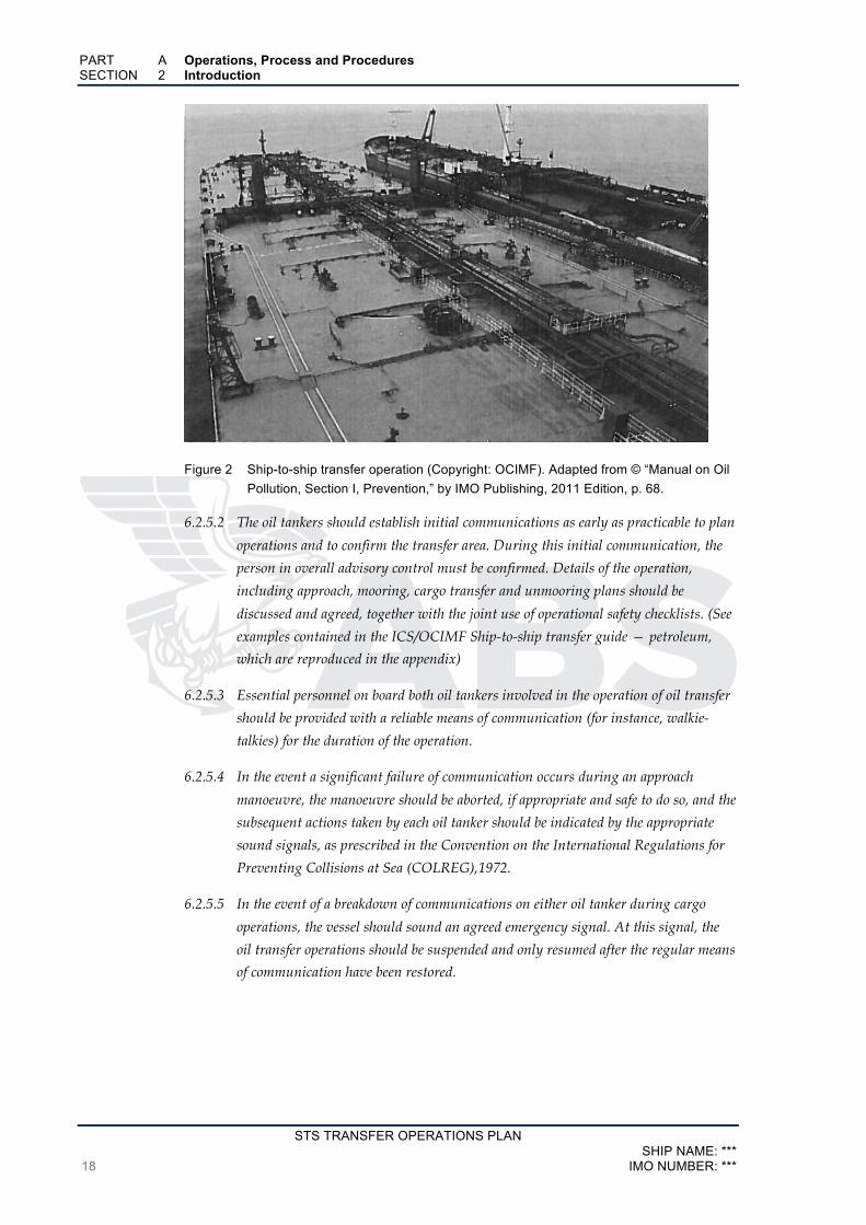
Figure 2 Ship-to-ship transfer operation (Copyright: OCIMF). Adapted from © “Manual on Oil Pollution, Section I, Prevention,” by IMO Publishing, 2011 Edition, p. 68.
6.2.5.2 The oil tankers should establish initial communications as early as practicable to plan
operations and to confirm the transfer area. During this initial communication, the
person in overall advisory control must be confirmed. Details of the operation,
including approach, mooring, cargo transfer and unmooring plans should be
discussed and agreed, together with the joint use of operational safety checklists. (See
examples contained in the ICS/OCIMF Ship-to-ship transfer guide — petroleum,
which are reproduced in the appendix)
6.2.5.3 Essential personnel on board both oil tankers involved in the operation of oil transfer
should be provided with a reliable means of communication (for instance, walkie-
talkies) for the duration of the operation.
6.2.5.4 In the event a significant failure of communication occurs during an approach
manoeuvre, the manoeuvre should be aborted, if appropriate and safe to do so, and the
subsequent actions taken by each oil tanker should be indicated by the appropriate
sound signals, as prescribed in the Convention on the International Regulations for
Preventing Collisions at Sea (COLREG),1972.
6.2.5.5 In the event of a breakdown of communications on either oil tanker during cargo
operations, the vessel should sound an agreed emergency signal. At this signal, the
oil transfer operations should be suspended and only resumed after the regular means
of communication have been restored.
PART A Operations, Process and Procedures SECTION 2 Introduction
STS TRANSFER OPERATIONS PLAN SHIP NAME: *** IMO NUMBER: *** 19
6.2.6 Equipment
6.2.6.1 Prior to starting the ship-to-ship transfer operation, the Masters of the oil tankers
should exchange information concerning the availability, readiness and compatibility
of the equipment to be used in the operation.
Fenders
6.2.6.2 The oil tanker(s) should be provided with fenders (primary and secondary). These
fenders should be capable of withstanding the anticipated berthing energies and
should be able to distribute the forces evenly over the appropriate area of the hulls of
both oil tankers. It is recommended that fenders constructed to ISO 17357 should be
used. Industry best practice is that the safety valve on pneumatic fenders is inspected
at intervals not exceeding two years and a certificate provided to demonstrate this.
6.2.6.3 Except in cases where the STS transfer is conducted using a dedicated lightering ship,
it is probable that fendering operations will be carried out with the assistance of an
STS service provider. Such companies usually have service craft available and these
vessels will normally assist in positioning fenders on the relevant oil tanker.
6.2.6.4 Fenders may be secured on either oil tanker. However, landing on an unprotected
hull section is less likely if the fenders are rigged on the maneuvering ship and it is
therefore preferable that fenders be secured to that ship.
6.2.6.5 The person in overall advisory control should advise the position and method of
securing the fenders to the oil tankers in advance of the operation.
Hoses
6.2.6.6 The hoses used for the STS transfer of crude oils or petroleum products should be
specially designed and constructed for the product being handled and the purpose for
which they are being used. Hoses used should comply with EN1765 (or latest
equivalent) with regard to specification for the assemblies and with BS1435 (or latest
equivalent) and OCIMF guidelines with regard to their handling, inspection and
testing. Hoses should bear the following durable indelible markings:
.1 the manufacturer’s name or trademark;
.2 identification of the standard specification for manufacture;
.3 factory test pressure (note: equal to rated working pressure,
.4 month and year of manufacture and manufacturer’s serial number;
.5 indication that the hose is electrically continuous or electrically discontinuous,
semi-continuous or anti-static
.6 the type of service for which it is intended, e.g. oil or chemical

PART A Operations, Process and Procedures SECTION 2 Introduction
STS TRANSFER OPERATIONS PLAN SHIP NAME: ***
20 IMO NUMBER: ***
6.2.6.7 Test data with respect to each hose should be available and should be sighted prior to
the hose being used for transfer.
6.2.6.8 Hoses should be withdrawn from service and retired against defined criteria, which
may include the following:
.1 the presence of defects detected during visual inspections. Defects prompting
retirement could include irregularities in the outside diameter, such as
kinking, damaged or exposed reinforcement or permanent deformation of the
casing and damage, slippage or misalignment of end fittings;
.2 after a defined period in service, established in consultation with the
manufacturer; and
.3 when the temporary elongation of the hose, measured during .routine
pressure tests, exceeds maximum allowable values.
6.2.6.9 A visual inspection of each of the hose assemblies should be carried out before they are
connected to the manifolds to determine that they are free of damage. If damage to a
hose or flange is present, the hose should be withdrawn from use for further
inspection, repair or retirement.
6.2.6.10 STS transfer operations require hose connections to be well made. Flanges or if used,
quick release couplings should be in good condition and properly secured to ensure
leak tight connections. Prior to transfer operations, hose integrity should be
confirmed at the manifold interfaces and intermediate flanges.
Mooring equipment
6.2.6.11 To ensure the security of moorings, it is important that both tankers are fitted with
good quality mooring lines, efficient winches and sufficiently strong closed fairleads,
bitts and other associated mooring equipment that is fit for purpose. Effective leads
between fairleads and mooring bitts and mooring winches should be available for the
handling of all mooring lines.
6.2.6.12 All fairleads used should be of the enclosed type, except on an oil tanker that will
always have a substantially greater freeboard than the other.
This will ensure that the fairleads remain effective in controlling mooring line as the
freeboard difference between the two oil tankers changes.
6.2.6.13 A prime consideration in mooring during STS operations is to provide fairleads and
bitts for all lines without the possibility of lines chaffing and against each other, the
oil tankers or the fenders.
6.2.6.14 Steel wire mooring lines and high modulus synthetic fiber ropes should be fitted with
synthetic fiber tails to provide the additional elasticity required for STS mooring
arrangements.

PART A Operations, Process and Procedures SECTION 2 Introduction
STS TRANSFER OPERATIONS PLAN SHIP NAME: *** IMO NUMBER: *** 21
6.2.6.15 A minimum of four strong rope messengers should be available on both oil tankers,
preferably made from a buoyant synthetic fiber material.
6.2.7 Precautions against pollution
6.2.7.1 All oil transfer operations should cease should an unsafe or environmentally
hazardous condition develop. Such conditions may include:
.1 failure of hoses or moorings;
.2 deterioration of weather and/or sea conditions;
.3 a dangerous concentration of gas on the deck of the oil tanker(s); and
.4 a significant spill of oil.
6.2.8 State of readiness for an emergency
.1 main engine and steering gear maintained ready for immediate use;
.2 cargo pump and all other equipment trips relevant to the transfer are tested
prior to the operation;
.3 crew are readily available and systems are prepared ready to drain and
disconnect hoses at short notice;
.4 oil spill containment equipment is prepared and ready for use;
.5 mooring equipment is maintained ready for immediate use with extra
mooring lines available at mooring stations as replacements in case of line
failure; and
.6 firefighting equipment is ready for immediate use.
6.2.9 Contingency planning and emergency procedures
6.2.9.1 Although STS transfer operations can be carried out safely, the risk of accident and
the potential scale of the consequences require that organizers develop contingency
plans for dealing with emergencies. Before committing to an STS transfer operation,
the parties involved should carry out a risk assessment covering operational hazards
and the means by which they are managed. The output from the risk assessment
should be used to develop risk mitigation measures and contingency plans covering
all possible emergencies and providing for a comprehensive response, including the
notification of relevant authorities. The contingency plan should have relevance to
the location of the operation and take into account the resources available, both at the
transfer location and with regard to nearby backup support.
6.2.9.2 Each oil tanker must assign emergency duties to designated members of the crew in
case of accidents that may arise during the transfer of oil, particularly in the case of
spillages of oil.
PART A Operations, Process and Procedures SECTION 2 Introduction
STS TRANSFER OPERATIONS PLAN SHIP NAME: ***
22 IMO NUMBER: ***
6.2.9.3 During each STS operation consideration should be given to having a tender or work
vessel available to deploy response equipment and to conduct clean-up of any oil
which may be spilled during the transfer operation.
6.2.9.4 The risk of oil pollution from STS Operations is no greater than during in-port cargo
transfers. However, as a transfer area may be out of range of port services, a
contingency plan with the Shipboard Oil Pollution Emergency Plan (SOPEP) or
Vessel Response Plan (VRP) should be available to cover such risk and should be
activated in the event of an oil spill.
6.2.9.5 Any leak or spillage during the transfer should be reported immediately to the officers
on cargo watch who should immediately stop the cargo transfer and notify the person
in overall advisory control. The immediate measures set forth in the contingency plan
should be implemented. The transfer should remain suspended until it is agreed
between the relevant persons/authorities that it is safe to resume.
6.3 Risk assessment
6.3.1 Risk assessment scope
STS operations should be subjected to a risk assessment, the scope of which should
include confirmation of the following:
.1 adequate training, preparation or qualification of the oil tanker’s personnel;
.2 suitable preparation of oil tankers for operations and sufficient control over
the oil tankers during operations;
.3 understanding of signals or commands;
.4 adequate number of crew assigned to controlling and performing oil transfer
operations;
.5 suitability of the agreed STS operations plan;
.6 adequate communications between oil tankers or responsible person(s);
.7 attention given to the differences in freeboard or the listing of the oil tankers
when transferring cargo;
.8 the condition of transfer hoses;
.9 methods of securely connecting hose(s) to the oil tanker(s) manifold;
.10 recognition of the need to discontinue oil transfer when sea and weather
conditions deteriorate; and
.11 adequacy of navigational processes.
6.4 Preparation for operations

PART A Operations, Process and Procedures SECTION 2 Introduction
STS TRANSFER OPERATIONS PLAN SHIP NAME: *** IMO NUMBER: *** 23
6.4.1 Preparations before maneuvers
Prior to the STS operation, the Masters of both oil tankers and, if appointed, the STS
Superintendent, should make the following preparations before maneuvers begin:
.1 carefully study the operational guidelines contained herein and in the
industry publication Ship-to-ship transfer guide —petroleum, as well as any
additional guidelines provided by the shipowner and cargo owner;
.2 ensure that the crew is fully briefed on procedures and hazards, with
particular reference to mooring and unmooring;
.3 ensure that the oil tanker conforms to relevant guidelines, is upright and at a
suitable trim;
.4 confirm that the steering gear and all navigation and communications
equipment are in satisfactory working order;
.5 confirm that engine controls have been tested and the main propulsion plant
has been tested ahead and astern;
.6 confirm that all essential cargo and safety equipment has been tested;
.7 confirm that mooring equipment is prepared in accordance with the mooring
plan;
.8 fenders and transfer hoses are correctly positioned, connected and secured;
.9 cargo manifolds and hose handling equipment are prepared;
.10 obtain a weather forecast for the STS transfer area for the anticipated period of
the operation;
.11 agree the actions to be taken if the emergency signal on the oil tanker’s whistle
is sounded; and
.12 confirm completion of relevant pre-operational checklists (see examples in the
appendix).
6.4.2 Communications
Communications with the master of the other oil tanker should be established in
accordance with 6.2.5 at an early stage to co-ordinate the rendezvous and the method
and system of approach, mooring and disengaging.
6.4.3 Confirmation of readiness
When the preparation of either oil tanker has been completed, the other vessel should
be so informed. The operation may proceed only when both oil tankers have confirmed
their readiness.

PART A Operations, Process and Procedures SECTION 2 Introduction
STS TRANSFER OPERATIONS PLAN SHIP NAME: ***
24 IMO NUMBER: ***
6.4.4 Joint Plan of Operation
A joint plan of operation in alignment with the STS operations plan established for
each ship should be developed on the basis of information exchanged between the two
oil tankers, including the following:
.1 mooring arrangements;
.2 quantities and characteristics of the cargo(s) to be loaded (discharged) and
identification of any toxic components;
.3 sequence of loading (discharging) of tanks;
.4 details of cargo transfer system, number of pumps and maximum permissible
pressure;
.5 rate of oil transfer during operations (initial, maximum and topping-up);
.6 the time required by the discharging oil tanker for starting, stopping and
changing rate of delivery during topping-off of tanks;
.7 normal stopping and emergency shutdown procedures;
.8 maximum draught and freeboard anticipated during operations;
.9 disposition and quantity of ballast and slops, and disposal if applicable;
.10 details of proposed method of venting or inerting cargo tanks;
.11 details of crude oil washing, if applicable;
.12 emergency and oil spill containment procedures;
.13 sequence of actions in case of spillage of oil;
.14 identified critical stages of the operation;
.15 watch or shift arrangements;
.16 environmental and operational limits that would trigger suspension of the
transfer operation, and disconnection and unmooring of the tankers;
.17 local or government rules that apply to the transfer;
.18 co-ordination of plans for cargo hose connection, monitoring, draining and
disconnection; and
.19 unmooring plan.
6.4.5 Alignment of cargo manifolds
The cargo manifolds of the two oil tankers should be correctly aligned.

PART A Operations, Process and Procedures SECTION 2 Introduction
STS TRANSFER OPERATIONS PLAN SHIP NAME: *** IMO NUMBER: *** 25
6.4.6 Suspension of Hoses
Hoses should be suspended in such a way that excessive strain on manifold fittings is
prevented and the possibility of twisting and pinching between the oil tankers is
minimized. Care should be taken to ensure that hoses are not bent to a radius less
than that recommended by the manufacturer and that they do not rub against the
ships’ structure.
6.4.7 Responsible person(s) requirements
Before commencing the cargo transfer operation, the responsible person(s) on the oil
tankers should ensure:
.1 proper mooring of the oil tanker;
.2 noting the information provided in the industry publication Ship-to-ship
transfer guide — petroleum, as amended, availability of safe and convenient
access between the oil tankers;
.3 availability of reliable communication between the two oil tankers;
.4 emergency signals and shutdown signals are agreed;
.5 proper connection and securing of hoses to the oil tanker’s manifolds;
.6 proper condition and position of hoses, hose saddles and supports;
.7 flanged joints where used, are fully bolted and sealed and ensured oil tight;
.8 proper blanking of unused cargo and bunker connections;
.9 tools required for the rapid disconnection of hoses are located at the manifold;
.10 any valve through which oil could be discharged to the sea is closed and
inspected and, if not used in the operation, is sealed to ensure that it is not
inadvertently opened;
.11 deck scuppers are properly plugged;
.12 availability of empty drip trays on both oil tankers under couplings of hoses,
and means for drip tray drainage;
.13 availability of materials on the oil tankers for on-deck clean-up in case of
spillage;
.14 fire axes or suitable cutting equipment is in position at fore and aft mooring
stations;
.15 an engine room watch will be maintained throughout the transfer and the
main engine will be ready for immediate use;
.16 a bridge watch and/or an anchor watch will be established;
.17 officers in charge of the cargo transfer are identified and details posted;

PART A Operations, Process and Procedures SECTION 2 Introduction
STS TRANSFER OPERATIONS PLAN SHIP NAME: ***
26 IMO NUMBER: ***
.18 a deck watch is established to pay particular attention to moorings, fenders,
hoses and manifold integrity;
.19 correct understanding of commands and signals by the responsible person(s)
on the oil tankers during operations; and
.20 confirm completion of relevant pre-transfer checklists.
6.4.8 Agreement between Vessels
The transfer operation may be started only after the responsible person(s) on both oil
tankers have agreed to do so, either verbally or in writing.
6.5 Performance of operations
6.5.1 Immediate checks on start of operation
The operation should be started at a slow rate in order to ensure that all connections
and hoses are tight, the oil is being directed into intended pipelines and tanks, no
excessive pressure is building up in the hoses and pipelines, and there is no evidence
of oil leakage in way of the tankers hulls.
6.5.2 Confirmation of normality and permissibility to continue transfer
Only after being satisfied that there is no leakage, the oil is being transferred into the
intended pipelines and tanks, and if there is no excessive pressure, may the rate of
transfer be increased up to the maximum indicated in the plan of operation.
6.5.3 Periodical checks
The responsible persons on both oil tankers should periodically check the following
and, if necessary, take appropriate remedial action:
.1 for any leakage from the equipment and system, or through the oil tanker’s
plating;
.2 that there is no leakage into pump rooms, ballast or void spaces or cargo tanks
not scheduled to be loaded;
.3 if there is any excessive pressure in piping and hoses;
.4 the mooring arrangements;
.5 the condition of hoses and their support arrangements; and
.6 tank ullages and quantities transferred.
PART A Operations, Process and Procedures SECTION 2 Introduction
STS TRANSFER OPERATIONS PLAN SHIP NAME: *** IMO NUMBER: *** 27
6.5.4 Caution to avoid surge pressures
Care must be taken to prevent surge pressures when changing over tanks on the oil
tanker being loaded. The filling valves of the next tanks in sequence should be opened
before the valves on the tank being filled are closed.
6.5.5 Exchange of Information
Information on quantities transferred should be routinely and regularly exchanged
between the two oil tankers. Any significant discrepancies between the quantity
discharged and the quantity received should be promptly investigated
6.5.6 Vapor Emission
Cargo operations should be conducted under closed conditions with ullage, sounding
and sampling ports securely closed. Due regard must be given to any local
regulations that may require the adoption of vapor balancing procedures.
6.5.7 Ballast Operations
During the cargo transfer, appropriate ballast operations should be performed in
order to minimize the differences in freeboard between the two oil tankers and to
avoid excessive trims by the stern. Listing of either ship should be avoided, except as
may be required by the discharging oil tanker between the oil tankers to facilitate tank
draining;
6.5.8 Attention to mooring lines
Constant attention should be paid to mooring lines and to avoid chafing and undue
stress, particularly that caused by changes in relative freeboard. If at any time
mooring lines need to be repositioned or adjusted, this should only be done under
strictly controlled conditions.
6.6 Completion of operations
6.6.1 Adequate ullage space
It should be ensured that adequate ullage space is left in each tank being filled. When
it is required to stop cargo transfer operations, the responsible person should advise
the pumping oil tanker in ample time.
6.6.2 Closure of valves and drainage of hoses
Upon completion of the oil transfer, the oil tanker with the greatest freeboard should
close the valve at the manifold and drain the oil contained in the hoses into the tank
of the other oil tanker. Any remaining oil in the hoses should be drained, after which
the hoses should be disconnected and securely blanked. The cargo manifolds should
also be securely blanked.

PART A Operations, Process and Procedures SECTION 2 Introduction
STS TRANSFER OPERATIONS PLAN SHIP NAME: ***
28 IMO NUMBER: ***
6.6.3 Coordination of unmooring plan
Following completion of any relevant checklists, the Masters should co-ordinate the
unmooring plan, taking into account weather and sea conditions prevailing in the
area.
6.6.4 Confirmation of items before unmooring
As soon as practicable after the transfer operation has been completed, and before
unmooring, the responsible person on each oil tanker should ensure that all valves in
their system are closed and cargo tank openings are closed and secured for sea.
6.6.5 Completion of documentation & unmooring
The oil transfer documents should be completed, communications checked and the
readiness of both oil tankers established, whereupon the ships should unmoor in
accordance with the plan.
6.7 Suspension of operations
6.7.1 Examples of reasons for suspension of operations
Both oil tankers should be prepared to immediately discontinue the STS transfer
operation, and to unmoor and depart if necessary. The operation should be suspended
when:
.1 movement of the oil tankers alongside reaches the maximum permissible and
risks placing excessive strain on hoses;
.2 under adverse weather and/or sea conditions;
.3 either oil tanker experiences a power failure;
.4 there is a failure of the main communication system between the oil tankers
and there are no proper standby communications;
.5 any escape of oil into the sea is discovered;
.6 there is an unexplained pressure drop in the cargo system;
.7 fire danger is discovered;
.8 any oil leakage is discovered from hoses, couplings, or the oil tanker’s deck
piping;
.9 overflow of oil onto the deck occurs caused by overfilling of a cargo tank;
.10 any faults or damage threatening the escape of oil are discovered; and
.11 there is a significant, unexplained difference between the quantities of cargo
delivered and received.

PART A Operations, Process and Procedures SECTION 2 Introduction
STS TRANSFER OPERATIONS PLAN SHIP NAME: *** IMO NUMBER: *** 29
6.7.2 Resumption of operations
Operations may be resumed only after the weather and seas have abated or
appropriate remedial action has been taken.
6.8 References
Table 6
No. Item 1 International safety guide for oil tankers and terminals (ISGOTT) -
(IAPH/ICS/OCIMF) 2 Ship-to-ship transfer guide- petroleum- (ICS and OCIMF) 3 Convention on International Regulations for Preventing Collisions at
Sea (COLREG), 1972-(IMO) 4 Convention on International Regulations for Preventing Collisions at
Sea (COLREG), 1972-(IMO) 5 Recommendations for oil tanker manifolds and associated
equipment - (OCIMF) 6 Guidelines for the handling, storage, inspection and testing of hoses
in the field - (OCIMF) 7 EN 1765:2004 - Rubber hose assemblies for oil suction and
discharge Services- specification for the assemblies (European Committee for Standardization-CEN)
8 BS 1435-2:2005 - Rubber hose assemblies for oil suction and discharge services - recommendations for storage, testing and use - (British Standards Institution - BSI)

PART A Operations, Process and Procedures SECTION 2 Introduction
STS TRANSFER OPERATIONS PLAN SHIP NAME: ***
30 IMO NUMBER: ***
2.4 Arrangement of the STS Plan and Event Log This STS Transfer Operation Plan has been arranged in three Parts with the inclusion
of the following items indicated below:
PART A Operations, Process and Procedures
SECTION 1 Ship Particulars
SECTION 2 Introduction
SECTION 3 Definitions
SECTION 4 Foundation of an STS Plan
SECTION 5 Conditions and Requirements
SECTION 6 STS Transfer Operations Safety
SECTION 7 STS Transfer Operations Communication
SECTION 8 STS Transfer Operational Preparations
SECTION 9 Maneuvering and Mooring
SECTION 10 STS Transfer Operation Procedures Alongside
SECTION 11 STS Transfer Operation Unmooring
SECTION 12 STS Transfer Operation Equipment
SECTION 13 STS Transfer Operation Emergencies
SECTION 14 References
PART B Appendices
PART C Event Log of STS Transfer Operation

STS TRANSFER OPERATIONS PLAN SHIP NAME: *** IMO NUMBER: *** 31
SECTION 3 Definitions
At sea Offshore waters, partially sheltered waters where transfer operations may take place
between vessels underway or at anchor.
Ballast The water carried in a ship’s ballast tanks.
Chock A guide for a mooring line, enabling the line to be passed through a ship’s bulwark or
other barrier. (Refer also to Fairlead).
Closed operations
Ballasting, loading or discharging operations carried out with provisions to enable
closed monitoring of tank contents, either by a fixed gauging system or by using
portable equipment passed through a vapor lock.
Company (Operator)
Ship owner, or an organization such as a ship manager or a bareboat charterer that has
assumed responsibility for the operation of the ship from the ship owner, including the
International Safety Management (ISM) Code mandated responsibilities.
Constant heading ship
During maneuvering and mooring, the ship that maintains course and speed to allow
the Maneuvering ship to approach and moor.
Daughter vessel
The smaller of the vessels engaged in ship to ship (STS) transfer operations. It may the
receiving ship or the discharging ship in reverse lightering procedures
Deadweight
Weight proportional to the lifting capacity of a ship, it includes cargo, ballast, fuel,
water and stores, without the inclusion of the light ship weight. The deadweight may
be determined for a corresponding draught from the ship’s tables.
Displacement
The total weight of a ship that is inclusive of all cargo, ballast, fuel, water, stores and
light ship weight. The displacement may also be determined for a corresponding
draught from the ship’s tables.
Emergency release coupling (ERC) or Dry break coupling
It consists of a coupling assembly that utilizes two valves, whereby one valve is fitted
upstream and the other valve downstream of the main valve body. It is installed
between the manifold presentation flanges and cargo transfer hoses on one of the
vessels conducting an STS transfer operation. It is designed to enable the ships to
separate in an emergency without the need to disconnect cargo hoses from the
manifold presentation flanges. It can be activated either from an emergency release
system (ERS) operating station or manually. When activated, the ERC valve body is
split into two separate sections and both the upstream and downstream valves are
closed to prevent or minimize loss of cargo from the cargo hose and ship’s cargo lines.
PART A Operations, Process and Procedures SECTION 3 Definitions
STS TRANSFER OPERATIONS PLAN SHIP NAME: ***
32 IMO NUMBER: ***
Emergency release system (ERS)
An ERS facilitates the release of all cargo transfer hoses by operation of the ERC(s) in
the event of an emergency such as ships breaking away from one another during an
STS operation. The system should initiate in the event of ship blackout
Emergency shutdown (ESD)
This system enables a sequential shutdown of ship cargo pumps and valves in the
event of emergencies.
Fairlead
A guide for a mooring line that enables the line to be passed through a ship’s bulwark
or other barrier or to change direction through a congested space without snagging or
fouling. (Refer also to Chock)
In Port Refers to an area where STS operations are conducted under the jurisdiction of a port or
harbor authority and includes operations that may involve berthing alongside a
Discharging ship or Mother ship at anchor or alongside a terminal.
Joint Plan of Operation (JPO)
Is an operation-specific plan that is inclusive of ship compatibility, maneuvering,
approach, mooring and transfer and, if applicable, the ship-specific STS operations plan.
Lightering area/zone
Refer to STS transfer area.
Lightering Master
Refer to STS Superintendent.
Lightering operation
Generic term for any STS cargo transfer operation.
Lightering ship or Service ship
A ship to which cargo is transferred from the Discharging ship.
Lightering support vessel
A vessel employed to transport equipment and personnel to the STS location and to
assist in preparing vessels for the operation.
Maneuvering
Is a term used when a vessel is:
• Making her final approach to another ship for the purpose of mooring
alongside the other to perform an STS operation; or
• Separating from another ship following an unmooring operation until
both ships are safely clear of each other.
Maneuvering ship
During maneuvering and mooring, the ship that approaches the Constant heading ship
for mooring operations is referred to as the Maneuvering ship.
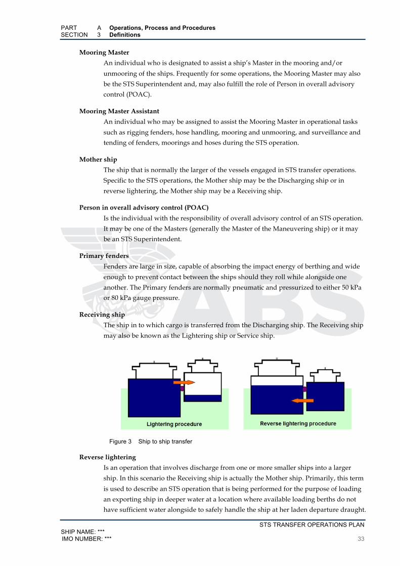
PART A Operations, Process and Procedures SECTION 3 Definitions
STS TRANSFER OPERATIONS PLAN SHIP NAME: *** IMO NUMBER: *** 33
Mooring Master
An individual who is designated to assist a ship’s Master in the mooring and/or
unmooring of the ships. Frequently for some operations, the Mooring Master may also
be the STS Superintendent and, may also fulfill the role of Person in overall advisory
control (POAC).
Mooring Master Assistant
An individual who may be assigned to assist the Mooring Master in operational tasks
such as rigging fenders, hose handling, mooring and unmooring, and surveillance and
tending of fenders, moorings and hoses during the STS operation.
Mother ship
The ship that is normally the larger of the vessels engaged in STS transfer operations.
Specific to the STS operations, the Mother ship may be the Discharging ship or in
reverse lightering, the Mother ship may be a Receiving ship.
Person in overall advisory control (POAC)
Is the individual with the responsibility of overall advisory control of an STS operation.
It may be one of the Masters (generally the Master of the Maneuvering ship) or it may
be an STS Superintendent.
Primary fenders
Fenders are large in size, capable of absorbing the impact energy of berthing and wide
enough to prevent contact between the ships should they roll while alongside one
another. The Primary fenders are normally pneumatic and pressurized to either 50 kPa
or 80 kPa gauge pressure.
Receiving ship
The ship in to which cargo is transferred from the Discharging ship. The Receiving ship
may also be known as the Lightering ship or Service ship.
Figure 3 Ship to ship transfer
Reverse lightering
Is an operation that involves discharge from one or more smaller ships into a larger
ship. In this scenario the Receiving ship is actually the Mother ship. Primarily, this term
is used to describe an STS operation that is being performed for the purpose of loading
an exporting ship in deeper water at a location where available loading berths do not
have sufficient water alongside to safely handle the ship at her laden departure draught.

PART A Operations, Process and Procedures SECTION 3 Definitions
STS TRANSFER OPERATIONS PLAN SHIP NAME: ***
34 IMO NUMBER: ***
Safe working load (SWL)
Generally a load less than the yield or failure load by a, safety factor that has been
defined by a code, standard or good engineering practice.
Secondary fenders
Fenders used to prevent contact between two ships, should they be rolling or not
parallel to each other. These fenders are especially effective when rigged towards the
ends of a ship and are offer the most benefit during mooring and unmooring
operations.
Service ship
Refer to Receiving ship.
Ship blackout
Loss of power.
Ship operator
See Company.
Ship to be lightered (STBL)
Refer to Discharging ship.
Ship to ship (STS) transfer operation
Where cargo oil is transferred between ships moored side-by-side. Such operations
may take place when one ship is at anchor or alongside or when both are underway. In
general, the expression includes the approach maneuver, mooring, hose connection,
procedures for cargo transfer, hose disconnection, unmooring and departure maneuver.
The operation may also be referred to as “transshipment”.
Standoff
The horizontal distance, maintained between the parallel body lengths of both ships,
which is provided by the primary fenders when conducting an STS transfer operation.
STS operations plan
A ship-specific plan containing procedures for the safe conduct of STS transfer
operations.
STS Organizer
An STS Organizer is a shore based operator responsible for arranging an STS transfer
operation. The Organizer may also be known as an STS Service Provider.
STS Service Provider
Companies sometimes employed to organize and assist with STS transfers. The services
offered by these companies vary, but often include the provision of personnel and
equipment to facilitate the STS transfer. An STS Service Provider may also supply the
essential personnel and equipment needed, such as hoses, fenders and support craft.
The STS Service Provider may also be referred to as an STS Contractor or STS Resource
Provider.
PART A Operations, Process and Procedures SECTION 3 Definitions
STS TRANSFER OPERATIONS PLAN SHIP NAME: *** IMO NUMBER: *** 35
STS Superintendent
A person who may be designated to assist a ship’s Master in the co-ordination and
supervision of the STS operation. This may include mooring and unmooring of the
ships and/or the cargo transfer operation.
For transfers at sea, the STS Superintendent may also assume the role of POAC.
The STS Superintendent may also be known as Lightering Master, Mooring Master or
Transfer Supervisor.
STS transfer area
An area within which an STS transfer operation customarily takes place. Transfer areas
should be selected in safe sea areas. In coastal areas these STS transfer areas will be
agreed to by nearby coastal authorities and, as appropriate, in accordance with specific
port or national regulations.
May also be described as a transshipment area.
Transfer at anchor
The expression Transfer at anchor describes an operation where a cargo transfer is
carried out between ships when they are moored alongside each other and where one
of the ships is at anchor.
Transfer Supervisor
See STS Superintendent.
Transhipment
Generic term for any STS cargo transfer operation.
Underway transfer
An STS operation that is conducted between two ships that are underway. A ship is
“underway” when it is not at anchor, made fast to the shore or aground. The ships
engaged in the transfer may either be steaming or drifting freely with current and
weather.
Vapor balancing
May be used to avoid the release of cargo vapors to the atmosphere by interconnecting
the vapor systems of the receiving and discharging ships.
STS TRANSFER OPERATIONS PLAN SHIP NAME: ***
36 IMO NUMBER: ***
SECTION 4 Foundation of an STS Plan
4.1 Preamble With the establishment of the use of suitable equipment, safe environmental
operating limits, the compliance with proper procedures and the experience obtained
from several regular operations, the STS transfer of oil cargoes at sea and in port has
become a common practice.
As detailed in Section 2 of this Plan, MARPOL 78/73, Annex I, Chapter 8 Regulations
40, 41 and 42, that entered in to force on 1 January 2011, requires oil tankers of 150
gross tonnage and above engaged in the transfer of oil cargo between oil tankers at
sea only (while underway or at anchor) conducted on or after 1 April 2012 to have
onboard an approved STS Plan. The information and requirements for STS transfers
in port is not a mandatory requirement by MARPOL and has been included as
additional information in this document.
4.3 Execution of Risk Assessments In order to identify, evaluate and estimate the levels of risks involved in an STS
Operation, their comparison against benchmarks or standards to enable a
determination of acceptability of levels of risk envisaged, a Risk Assessment is to be
carried out for the following sections of STS Operations, which are not exhaustive:
i) A risk assessment for the suitability of an STS Transfer Location in
accordance with Subsection 6.2.1, Risk assessments considering the
stagnation of gas pockets in accordance with Subsection 6.6
ii) A risk assessment - for the suitability of a Ship to Ship Transfer
Operation in accordance with Subsection 6.2.2; for vessels of similar
length in accordance with Subsection 5.2.1
iii) A risk assessment for Personnel Transfers at sea in accordance with
Section 12.4
Appendix G details the methodology and general considerations to be used for the
execution of a risk assessment.
4.2 Scope The CDI/ICS/OCIMF/SIGTTO “Ship-to-Ship Transfer Guide for Petroleum,
Chemicals and Liquefied Gases”, 2013 (STS Guide) includes the best practices and
guidelines for the transfer of petroleum, chemicals and liquefied Gases at sea and in
port also.
This STS plan however includes Ship-to-Ship Transfer best practices and guidelines
for the transfer of petroleum only at sea and in port and is intended to indicate
offshore waters or partially sheltered waters.
Section 3 of this plan describes the common terminology of a Discharging ship,
Receiving ship, Mother ship and Daughter vessel, which has been used throughout

PART A Operations, Process and Procedures SECTION 4 Foundation of an STS Plan
STS TRANSFER OPERATIONS PLAN SHIP NAME: *** IMO NUMBER: *** 37
this plan. Similarly, the terms Mooring Master, Person in Overall Advisory Control
(POAC), STS Superintendent have been used to describe key roles associated with an
STS operation.
Though this STS plan is used for regular and normal STS transfer operations, it may
also be of assistance when carrying out emergency STS transfer operations. However,
in addition to this plan depending on the unique circumstances of each emergency
situation, the procedures adopted may vary from one situation to another, which
would entail the use of other approved procedures.
4.4 Centralized Control of Operations 4.4.1 General
The control of STS transfer operations will be conducted and coordinated under the
advisory control of one of the following individuals in accordance with MARPOL
78/73, Annex I, Chapter 8 Regulations 41.4, based on the experience of the concerned
individual and the avoidance of an appointed individual suffering from fatigue:
i) Either of the Masters of the concerned vessels,
ii) an STS Superintendent or
iii) a POAC
For the prevention of fatigue during extended operations, the centralized control will
be formally transferred to another suitably qualified person. See paragraph 4.4.2
below.
This vessel will employ an STS Superintendent for the purpose of advising
inexperienced Masters involved in STS transfer operations.
Depending on prevailing needs, an STS Service company will be contracted to
provide experienced STS Superintendents and, where required, qualified POACs
The above arrangements are not intended to comprise or relieve this vessel’s Master
of his overall authority, duty or responsibilities.
The Master of each vessel will continue to remain in command of his vessel, crew and
cargo, and under no circumstances will permit the safety of the vessels to be affected
by the actions of others.
Prior to the commencement of an STS transfer operation, the Masters of each vessel,
together with the STS Superintendent or POAC, will discuss the key non-exhaustive
components of the operation as would be applicable:
i) Fendering
ii) Maneuvering
iii) Mooring
iv) Hose connection,

PART A Operations, Process and Procedures SECTION 4 Foundation of an STS Plan
STS TRANSFER OPERATIONS PLAN SHIP NAME: ***
38 IMO NUMBER: ***
v) Cargo transfer
vi) Hose disconnection
vii) Unmooring, and
viii) Unfendering
The discussions on the above components will ensure that the key personnel
involved in the operation clearly understand and agree how the operation will be
conducted and agree to the contents of the joint plan of operation (JPO) detailed in
Section 8.2).
4.4.2 Adequate manning and prevention of fatigue during STS Operations
When underway or at anchor, throughout the entire duration of the STS operation a
proper deck and bridge watch will be maintained on each vessel underway or at
anchor. The principles of bridge team management will be observed. See Subsection
14/11 “Bridge Procedures Guide”
When alongside in port, normal safe deck and cargo watchkeeping duties should be
maintained by the vessels involved.
Special considerations and measures will be adopted since STS transfer operations
places additional demands on the ships’ crew, as personnel will not only be required
for the cargo transfer operations and tending of moorings, but also to keep a safe
navigational or anchor watch throughout the STS transfer operation.
The highest attention will be given to avoid human error caused due to fatigue.
In the planning phase of the STS transfer operation, the Masters of the vessels, in
coordination will estimate the duration and complexity of the operation and a
resulting assessment will be made taking in to consideration the additional
workloads associated with the STS operation. The excess noise levels in the vicinity of
rest areas will also be given due consideration.
The drawn up plans would ensure that all personnel inclusive of STS
Superintendents, POACs, Mooring Masters and other involved individuals will
remain fatigue free and that minimum rest periods, as required by applicable
legislation, are complied with, particularly when conducting multiple transfers. As
deemed and if required by the Master, additional personnel will be placed on board
to assist with the STS transfer operations.
4.5 Responsibility of STS Superintendent The STS Superintendent will ensure, through professional advice and guidance to the
Master(s), the necessary co-ordination and safe completion of an STS operation.
STS Superintendent will:
i) Review the location-specific risk assessment
ii) Review the JPO and its associated risk assessments
PART A Operations, Process and Procedures SECTION 4 Foundation of an STS Plan
STS TRANSFER OPERATIONS PLAN SHIP NAME: *** IMO NUMBER: *** 39
iii) Will verify that the agreed STS operating procedures are adhered to
and that the STS operation is conducted in compliance with all
applicable regulatory requirements
iv) Confirm that all the necessary reports are forwarded to the
appropriate authorities
v) Confirm that all relevant checklists have been completed
vi) Oversight of the correct placement of primary and secondary fenders
vii) Sights and reviews mooring equipment
viii) Conduct a pre-operation discussion with the responsible individuals
of the vessels involved, inclusive of lightering support vessels and tugs,
as applicable
ix) Confirm that personnel involved in each part of the operation are
properly briefed and understand their responsibilities
x) Confirm currents and forecasted environmental conditions and the
continuous monitoring throughout the STS operations
xi) For at sea transfers, complete discussions on passage planning, courses
and speeds for maneuvering and mooring operations
xii) Verify acceptable joint agreements of the mooring and unmooring
plans.
xiii) Review and verify that any site-specific risk mitigations have been
addressed
xiv) Supervise vessel approaches and maneuvering alongside
xv) Confirm the safe connection of transfer hoses/arms and any associated
emergency release systems (ERS)
xvi) Verify that any emergency shutdown system (ESD) has been installed
and tested
xvii) Confirm that cargo transfer rates are regularly monitored together
with associated vapor management procedures
xviii) Verify that the mooring arrangement and its integrity are being
regularly monitored
xix) Ensure that in the case of emergencies the associated contingency
plans are activated
xx) Verify that cargo transfer lines are adequately drained and, where
required, purged
xxi) Confirm the safe disconnection of hoses and arms as applicable
xxii) Supervise the successful unmooring and the separation of vessels

PART A Operations, Process and Procedures SECTION 4 Foundation of an STS Plan
STS TRANSFER OPERATIONS PLAN SHIP NAME: ***
40 IMO NUMBER: ***
xxiii) Supervises where applicable, the smooth return of primary and
secondary fenders and transfer equipment
xxiv) The STS Superintendent, Mooring Master Assistant, as applicable is to
advise the Master when the STS operation should be suspended or
terminated
4.6 Person in Overall Advisory Control (POAC) Refer to Subsection 2.3/6.2.1.3
4.7 Training and Familiarization of Ship’s Personnel 4.7.1 General
It is imperative that the risk assessment prior the STS operation would identify a
situation wherein several crew would be required to take on additional or dissimilar
tasks and assuming different roles and responsibilities than they would, when
involved in routine port and cargo operations. The risk assessment may also identify
emergency scenarios that may not be contained in the vessel’s regular drill programs.
These additional roles and responsibilities are to be identified for each STS operation
and accordingly suitable training is to be provided prior to the STS operation.
The training requirement for each ship will differ depending on the experience level
of the individuals on board.
The training required will be dependent factors such as location of transfer, service
providers, type of equipment, etc. that will be used. Such additional training may be
also required for experienced personnel.
Where there is a lack of experience with STS operations, due consideration will be
given to making provisions for additional experienced STS personnel prior to the STS
operation to assist with the training of personnel and the STS operation.
4.7.2 Components of Training
The following are the minimum aspects of training that will be imparted:
i) Responsibilities and Roles of all involved individuals
ii) Bridge watchkeeping and Deck watchkeeping procedures
iii) Operation of machinery
iv) Mooring and unmooring
a) Procedures adopted for passing lines between vessels
b) Quick release systems
c) Mooring lines properties
d) Management of Fenders
e) Measures to be adopted for minimize chafing of lines

PART A Operations, Process and Procedures SECTION 4 Foundation of an STS Plan
STS TRANSFER OPERATIONS PLAN SHIP NAME: *** IMO NUMBER: *** 41
f) Snap-back zones awareness
v) Operation of cranes
vi) Personnel transfer
vii) Transfer equipment
viii) Connection and disconnection of hoses/arms
ix) Hose slinging and support arrangements
x) Emergency operations:
a) Aborting mooring operations
b) Collision
c) Cargo spill
d) Emergency disconnection and departure
Based on an individual’s past experience and the roles assumed, the level of
knowledge and training that will be imparted will be tailored accordingly. Based on
the specific circumstances prevailing the specific Joint plan of Operation will to be
discussed with the vessel’s staff to ensure they have a good understanding of the STS
transfer operation.
4.8 Security of the Vessels Involved in the STS Transfer Operation Each vessel involved in the STS transfer operation will be responsible for its own
security throughout the STS transfer operation. International Ship and Port Facility
Security (ISPS) Code, any local regulations, any security levels imposed will be
stringently adhered to.
Exclusion zones around the STS transfer operation mandated by local regulations
will be adhered to.
Safe distances from other vessels will be established at all times and appropriate
actions will be taken if such distances are compromised.
The following security issues at a minimum will be discussed and the associated
decisions recorded, prior to the commencement of the STS transfer operation:
i) Exchange of sufficient information to determine if a Declaration of
Security is required
ii) Agreement on how, and between whom, communications regarding
security are to be made
iii) Actions to be taken in the event of a breach of security, such as
suspending operations and the separating of vessels

PART A Operations, Process and Procedures SECTION 4 Foundation of an STS Plan
STS TRANSFER OPERATIONS PLAN SHIP NAME: ***
42 IMO NUMBER: ***
4.9 Security Associated with Multiple Vessels Vessels alongside, the port and the terminal, will each have security plans in
compliance with the ISPS Code and the concerned local and/or country codes The
STS Superintendent should be aware of the current security requirements and
security level imposed by the port and this information should be conveyed to all
concerned vessels coming alongside.
For transfer operations that take place alongside a terminal, the terminal and the
gangway security will monitor all personnel movements from the shore.
It is a necessity that other vessels coming alongside the ship moored or alongside the
terminal identify any visitors they expect.
The entry of unidentified visitors should not be permitted unless permission has been
granted by the concerned vessel alongside.
During the planning stage of an STS operation, a security assessment is required to be
completed. However, if a concern arises that there is an inadequate measure of
addressing the security aspect in port, a risk analysis should be undertaken of all
elements of the STS transfer for the terminal and vessels alongside.
The assessment should include at least the following:
i) Assessment of the security systems and procedures in place
ii) Assessment of the infrastructure and the assets to be protected
iii) Identification of any threat to the port, terminal, discharging ship and
vessels alongside
iv) Assessment of areas of operation vulnerable to security threats
v) Include also weaknesses in the infrastructure, security policies and
procedures

STS TRANSFER OPERATIONS PLAN SHIP NAME: *** IMO NUMBER: *** 43
SECTION 5 Conditions and Requirements
5.1 Ship to Ship Compatibility A compatibility assessment executed, which is a prerequisite to be considered for
planning an STS transfer operation will ensure that the ships involved are compatible
with each other in design and equipment. Based on the assessment, items that may
require specific management aspects will be identified.
The following information at the first opportunity and as a minimum will be shared
with the Masters of the involved vessels:
i) overall dimensions
ii) freeboard
iii) position of manifolds
iv) mooring points, and
v) fenders
The initial information required in Checklist 1 should be made available by the ship
managers to the organizers and, where appropriate, STS service providers.
5.2 Compatibility Assessment The following are non-exhaustive items that are to be included in the compatibility
assessment:
i) Vessel characteristics as per the STS operations plan. Refer to Checklist
1.
ii) Minimum maneuvering speeds and corresponding revolutions per
minute (RPM)
iii) Manifold arrangements, sizes and number to be used
iv) Number of hose connections available
v) Minimum and maximum expected height of the cargo manifold from
the waterline during the transfer operation and the freeboard
differences during the cargo transfer
vi) Confirmation that the hose handling cranes or derricks are in a
satisfactory condition, and are of suitable safe working load (SWL)
with an appropriate outreach
vii) Adequate hose supports at the ship’s side to prevent damage to hoses
through chafing
viii) Cargo pumps type and cargo handling equipment, and if applicable,
restrictions to be imposed to ensure a safe transfer rate for the
products to be handled

PART A Operations, Process and Procedures SECTION 5 Conditions and Requirements
STS TRANSFER OPERATIONS PLAN SHIP NAME: ***
44 IMO NUMBER: ***
ix) Maximum permitted pumping/receiving rates design for the vessels
involved
x) Mooring arrangements, including the type of mooring lines and the
requirements for enclosed fairleads
xi) For vessels of similar length, the identification of associated issues (see
Subsection 5.2.1)
xii) Arrival and departure displacement, draught, freeboard and parallel
body length and associated fendering requirements
xiii) Hazardous zone diagrams, both horizontal and vertical, and gas safe
areas, taking into account the changing cargo deck heights and
overlapping flammable zones of the ships involved
xiv) Potential for release of toxic vapor and identification of hazardous
zones.
xv) Assessment of information relating to any clear air flow obstructions
that may cause eddies to be created, affecting the shape and
concentration of any gas plumes from vents. Identification of heights
of vents from smaller vessels, which may result in a hazard on the
elevated deck or operational area of a larger vessel alongside.
xvi) Direction of wind and hazards associated with flue gases and sparks,
particularly when ships are moored stem to stern
xvii) Personnel transfer arrangements, if applicable
xviii) Emergency shutdown (ESD) and communication systems
xix) Contingency planning and emergency procedures
xx) Cargo transfer and ballast plans, including assessed duration
xxi) Vapor management capacity of each vessel and, where vapor
return/balancing is used, the compatibility and capacity of ship
systems
xxii) Precautions to be exercised and the associated mitigation measures
with respect to the prevention of bridge wings from coming in to
contact with the other vessel, or with structures such as lifeboats on
the main deck. For vessels of similar size longitudinal offset of
manifolds and the use of larger fenders
5.2.1 Vessels of Similar Lengths Involved in STS Transfer Operations
Vessels having a length overall (LOA) difference of less than 10% would in general be
considered as being of a similar length. The following mitigation measures are to be
included in the risk assessment for the STS transfer operation, to reduce the risk to an
acceptable level:
PART A Operations, Process and Procedures SECTION 5 Conditions and Requirements
STS TRANSFER OPERATIONS PLAN SHIP NAME: *** IMO NUMBER: *** 45
i) The identification of an optimum mooring arrangement. If applicable,
additional lines in a fore and aft direction to compensate the headlines
being in a breast line configuration
ii) The identification of optimum securing arrangements for fenders to
ensure that arrangements for mooring are not affected due to a lack of
useable chocks/fairleads
iii) For the purpose of offsetting the bridge wings, adjustment of the fore
and aft positions of the ships. With these adjustments it will be
ensured that the primary fenders will rest on the parallel body of both
the vessels at all times throughout the transfer operation and that the
hose lengths provided will be adequate to accommodate the resulting
manifold offset
iv) For transfer operations conducted at anchor with one of the vessels
offset, extra headlines will be provided to counter the additional forces
on the vessel with the exposed bow
v) Larger diameter fenders will be provided to increase separation
distances
vi) The environmental parameters that have a limiting result will be
reduced, once the lead and effectiveness of the mooring line
configuration have been adequately considered
5.2.2 The use of Dumb Barges
STS transfer operations may involve the use of dumb barges. The barge is under the
responsibility of the barge operating company. The tug Master is the responsible
person when the barge is being towed or pushed by the tug.
For mooring, unmooring and during transits, the tug crew is responsible for the
handling of the barge. When alongside a berth or discharging vessel, the barge comes
under the facility’s security plan. During cargo operations, an operator either
belonging to the tug or appointed by the barge company takes charge of the barge
and is responsible for ensuring safe operations.
The cargo pumps on a barge are driven by their own independent diesel power units.
Modern barges are installed with float-type high level gauges with audible alarms,
these are usually powered by portable power units (battery packs), that are brought
on board by the operator. It should be noted that dumb barges do not have fixed fire-
fighting capability, so portable fire extinguishers are to be placed on board during
cargo operations. The STS Superintendent should always be aware of when barges
are alongside the discharging ship and of any other vessels involved in the transfer
operations.
It should be ensured that adequate fire-fighting capability is available to cover the
operations of the dumb barges.

PART A Operations, Process and Procedures SECTION 5 Conditions and Requirements
STS TRANSFER OPERATIONS PLAN SHIP NAME: ***
46 IMO NUMBER: ***
The challenges for mooring operations that may be presented by barges would
include the following:
i) Limited number of mooring ropes available
ii) Limited number of winches
iii) Limited number of chocks or open type chocks
iv) Difficulty in establishing effective mooring leads
The equipment and operational practices used by dumb barges may differ in many
respects from those recommended in this plan for conventional STS operations. In
such cases, it is recommended that this Guide is used to provide an operational
benchmark for information that assists in ensuring the safety of such operations.
5.3 Notification to and Approval from the Authorities 1) An oil tanker that plans STS operations within the territorial sea, or the
exclusive economic zone of a Party to the Convention shall notify that Party
not less than 48 hours in advance of the scheduled STS operations.
2) In an exceptional case, if the information specified in 5.3.3 below is not
available in less than 48 hours in advance, the oil tanker discharging the oil
cargo shall notify the Party, not less than 48 hours in advance that an STS
operation is to occur and the required information shall be provided at the
earliest opportunity.
3) The notification required in 5.4.1 is to include at least the following
information:
i) Name, flag, call sign, IMO number and estimated time of arrival of the
vessels involved in the STS operation
ii) Date, time and geographical location at the commencement of the
planned STS operation
iii) Whether the STS operation is to be conducted at anchor or underway
iv) Oil type and quantity
v) Planned duration of the STS operation
vi) Identification of STS service provider or person in overall advisory
control (POAC) and contact information; and
vii) Confirmation of an approved STS Plan on board the vessels
4) If the estimated time of arrival of a tanker for the STS operation changes by
more than six (6) hours, the STS Organizer, Master, owner or agent of that
tanker is to provide a revised estimated time of arrival to the authority.
PART A Operations, Process and Procedures SECTION 5 Conditions and Requirements
STS TRANSFER OPERATIONS PLAN SHIP NAME: *** IMO NUMBER: *** 47
5.4 Transfer Area for STS Transfer Operations 1) Transfer areas may be defined by the appropriate coastal State authorities.
The size of transfer areas selected varies considerably and the space available
for the transfer would have a direct relation to the type of manoeuvre that
would be used for the STS operation.
If both ships are intended to be underway, a relatively large transfer area
would be required. Whereas if one ship is required to approach the other
ship.at anchor a much smaller overall area would be required.
2) A safe STS transfer area around the vessels should be agreed to by both
vessels and monitored accordingly.
Some coastal state authorities may require a safety patrol vessel to be on
station throughout the STS transfer operations.
3) For transfers alongside terminals, consideration should be given to passing
ships, traffic density and if local regulations allow double banking.
4) During the pre-arrival planning phase, the STS Organizer should take into
account the following in selecting the area for STS transfer:
i) Notify and obtain appropriate approval from the applicable Coastal
authority
ii) The traffic density in the selected transfer area
iii) The need for sufficient sea-room and water depth required for
maneuvering during approach, mooring and unmooring
iv) Availability of safe anchorage with good holding ground
v) Forecast weather conditions and availability of weather reports in the
selected transfer area
vi) Distance from shore logistic support and availability of emergency and
oil spill response capability
vii) Proximity to environmentally sensitive areas
viii) Locations of underwater pipelines, cables, artificial reefs or historic
sites
ix) Potential security threats
5.5 Environmental Conditions 5.5.1 General conditions and measures
Various environmental conditions prevalent in the transfer location may impose
restrictions on the STS operation. Some coastal state authorities may have regulations
that would limit STS operations under adverse weather conditions.

PART A Operations, Process and Procedures SECTION 5 Conditions and Requirements
STS TRANSFER OPERATIONS PLAN SHIP NAME: ***
48 IMO NUMBER: ***
i) It is impractical to generalize limiting weather conditions under which
an STS operation can be performed since much will depend on the
effect of the sea and swell on the fenders and the movements induced
in the participating vessels, taking in to account their relative
displacement and freeboard
ii) STS operations in locations subjected to long period waves should be
treated with caution
iii) When a STS transfer is to take place at anchor, the combined effect of
current and weather conditions on the movements of the moored
tankers and the ultimate stress on the anchor cable should be carefully
considered
iv) Available weather forecasts for the transfer area, supplemented by
information from facsimile weather records, are to be obtained before
operations begin
v) Throughout the berthing operation, visibility conditions are required
to be safe for maneuvering, taking into account navigation and
collision avoidance requirements
The Master of any ship involved in the operation retains the right to suspend
operations and unmoor, should he have concerns regarding the safety of the ships
remaining alongside in the prevailing weather and sea state conditions. In general
information that will determine the operational management action should include,
but are not be limited to: visibility; wind speed and direction; wave and swell height,
period and direction, Weather forecasts etc..
Operations in port, would be affected by weather factors that could influence the
available depth of water, tidal heights, currents and sea states in exposed waters.
Under keel clearances should be constantly monitored and due account is to be taken
of any temporary restrictions to the vessel’s draught, that may often be a requirement
of the local authorities.
5.5.2 Precautions and measures in cold weather conditions
Extreme cold weather conditions at the transfer areas mandate additional precautions
to be taken to ensure the safety of personnel and the immediate availability of
essential ship systems. Guidance measures may be found in national or international
publications such as “The Use of Large Tankers in Seasonal First Year Ice and Severe
Sub-Zero Conditions”
The following is a non-exhaustive list of pertinent considerations:
i) Provision of appropriate cold weather clothing
ii) The potential for slips and falls on icy surfaces
iii) The suitability of fenders and cargo transfer equipment

PART A Operations, Process and Procedures SECTION 5 Conditions and Requirements
STS TRANSFER OPERATIONS PLAN SHIP NAME: *** IMO NUMBER: *** 49
iv) The readiness of safety and fire-fighting systems
v) The proper functioning of pneumatic, steam and hydraulic systems
vi) The correct operation of quick release couplings (QRCs)
vii) The proper operability of high velocity vents, purge pipes, pressure
vacuum breakers, ballast tank vents and cargo/ballast system valves
viii) As appropriate, ensuring that safety showers and eye wash facilities
remain in an operational condition
ix) Oil spill plans and oil spill response plans may need to be revised if
applicable, to consider cold weather and ice conditions
x) The lower temperatures associated with cold weather may create low
lying, heavier than air flammable vapor that could spread over the
side of the hull on to the lower vessel
5.5.3 Ship to ship operations in ice conditions
STS transfer areas may have ice conditions that could vary from solid pack to open
sea.
Prior to undertaking any STS transfers in such areas, the following non-exhaustive
conditions are to be duly considered:
i) The experience that ship’s personnel and service providers have of
operating in ice
ii) The shelter that operating in ice areas offers. Swell, and particularly
sea conditions, may be reduced or eliminated within the ice edge
iii) Accessibility to the designated STS position for the vessels involved
iv) The suitability and ice classification of the ships’ hulls to allow
operations in ice conditions
v) The need for ice breaking support
vi) Fendering considerations will depend on the conditions, but the
possibility of the ice itself acting as a fendering agent between the
ships should be considered
vii) The possibility of structural damage caused by ships compressing the
ice between the hulls or from a higher ice classed vessel causing
damage to a lower ice classed vessel’s hull
viii) Contingency plans should address the requirement for safely breaking
away in the event of an emergency
ix) The oil spill contingency plans should allow for the possibility of
products being contained either on the ice or within the open water
surrounded by broken ice. Spill response equipment should be capable
of operating in the temperatures to be encountered

PART A Operations, Process and Procedures SECTION 5 Conditions and Requirements
STS TRANSFER OPERATIONS PLAN SHIP NAME: ***
50 IMO NUMBER: ***
x) If engines are to be run to keep the propellers and rudders clear of ice,
it will need an agreement between the vessels
If the safety and the security of the fender moorings or vessel mooring arrangements
have a reasonable chance of failing due to the actual or potential buildup of ice
causing a probable adverse impact, the STS operation should be discontinued.
5.5.4 Sloshing of cargo tanks
STS transfer operations that are subjected to adverse weather conditions may result
in rolling and pitching of the vessels involved which would in turn result in the
sloshing of cargo in slack.
In general the following are to be considered at a minimum:
i) Maintaining safe operational and environmental limits thereby
ensuring that risks of damage to cargo tank structures and fittings are
minimized
ii) Static accumulation of cargo or cargo mixed with water causing an
electrostatically charged mist
iii) P/V valves must operate correctly if the movement of the cargo liquid
creates excessive pressure fluctuation in the vapor space of the cargo
tanks
iv) Linked shutdown systems may be prematurely activated due to
frequent variations in the tank levels
v) To lower the possibility of exposure free surfaces in the cargo tanks of
the vessels, the loading and discharge are to be optimized
vi) In order to minimize the effect of sloshing loads consideration may
need to be given to suspending operations for a period of time
5.6 Ship to Ship Service Providers Quality Assurance (QA) requirements To ensure an STS transfer operation is conducted safely, reliably and efficiently, it is
necessary for STS Service providers to offer quality services.
International standards for maintaining the quality of services offered by STS service
providers is at present absent.
However, STS service providers are to be assessed based on their previous industrial
experience.
“Ship to Ship Service Provider Management Inc. STS Service Provider Self-
Assessment” Subsection 14/9 published by OCIMF may be used by STS service
providers as a guidance bench mark to comply with the expected essential elements
of a good safety and environmental management system to cover STS operations.
STS TRANSFER OPERATIONS PLAN SHIP NAME: *** IMO NUMBER: *** 51
SECTION 6 STS Transfer Operations Safety
6.1 General Requirements The Master of each vessel involved in STS transfer operations is responsible for the
safety of his vessel, her crew, equipment and cargo. The Master should not permit his
vessel’s safety from reaching an unsafe state by the erroneous actions of others.
Reference to the appropriate sections of the 'International Oil Tanker and Terminal
Safety Guide', (ISGOTT), which is maintained onboard, would assist in operational
advice to personnel involved in tanker operations, including guidance on and
examples of certain aspects of tanker operations and how they may be managed.
It is a general industry recommendation that a copy of ISGOTT is to be kept and used
onboard every tanker so that there is a consistent approach to operational procedures
and shared responsibilities for operations at the ship/shore interface.
ABS recommends that the Ship’s Cranes are certified for personnel lifting in
accordance with the requirements of the ABS Guide for Certification of Lifting
Appliances.
6.2 Risk Assessment 6.2.1 Transfer Location Risk Assessment
6.2.1.1 STS transfer operations conducted at sea may be beyond receiving possible
assistance from port services, such transfers may require considerations
which are specific in nature
6.2.1.2 Each specific transfer location is to have its specific risk assessment. The
results of the risk assessment would be used for the development of specific
operational procedures and safeguards for the specific location
6.2.1.3 The safeguards, mitigation measures and controls that may be applied to
address the identified risks may result in the residual risks that may also
require additional consideration
6.2.1.4 In general, for the risk assessment, the following are to be considered as a
minimum. Factors considered in the risk assessment should include the
following:
i) Requirements derived from Local legislation
ii) The transfer location and if applicable its shelter being exposed to
environmental conditions inclusive appropriate met ocean analysis of
wind, wave, climatic conditions, seasonal variations etc.
iii) Whether transfer operations are to be conducted while both vessels are
underway, or at anchor
iv) In the vicinity of the transfer location the traffic density & the presence
of other STS activities.

PART A Operations, Process and Procedures SECTION 6 STS Transfer Operations Safety
STS TRANSFER OPERATIONS PLAN SHIP NAME: ***
52 IMO NUMBER: ***
v) Potential environmental effect of oil spills and the associated probable
dispersion trajectories
vi) Additional spill response resources requirement for the specific
location
vii) Support craft availability at the transfer location and their capabilities
viii) The integrity of resources and operations provided by local
subcontractors on site
ix) Transfer location’s exposure to security threats
x) Criteria of aborting the STS transfer based on environmental limits,
including abort criteria
xi) In the vicinity of the transfer location navigational hazards
6.2.1.5 A mooring analysis as appropriate is to be conducted to identify the
environmental operating parameters. To ensure that a risk analysis is fit for
purpose if any changes to identified hazards are recognized, the risk
assessment should be updated accordingly.
6.2.2 Ship to Ship Transfer Operation Risk Assessment
6.2.2.1 Elements to be included in a Risk assessment
An important part of the pre-STS planning process is the element of carrying
out a risk assessment. Prior to conducting an STS transfer operation, a risk
assessment is to be conducted with sufficient information to ensure a good
understanding and effective control of the transfer operation.
The suitability of equipment, the physical and operational hazards and the
modes of management are to be included in the risk assessment.
As a minimum a risk assessment should consider the following:
i) Compatibility of ships
ii) Mooring arrangements
iii) Transfer location suitability for the specific ships
iv) The properties of the cargo to be transferred
v) Qualification, training and experience of personnel to be involved
vi) For the proposed operations of the vessels the adequacy of the
required preparations
vii) Sufficiency of control during operations
viii) Adequate processes for navigation
ix) Adequacy of the number of personnel involved
PART A Operations, Process and Procedures SECTION 6 STS Transfer Operations Safety
STS TRANSFER OPERATIONS PLAN SHIP NAME: *** IMO NUMBER: *** 53
x) Measures for adequate communication between ships and responsible
individuals
xi) Effect of variances in the freeboard of vessels during the period of
transfer
xii) Adequacy of transfer hoses, fenders and suitability of equipment
xiii) Environmental conditions anticipated
xiv) Planning of emergency procedures
6.2.2.2 Generic risk assessments
A generic risk assessment may be found appropriate for a specific transfer
location, utilizing standard approved type of STS equipment for vessels that
are fully operational.
However, if a generic risk assessment is to be made use of, the hazards
specific to the operation being planned must be clearly identified and
adequately addressed.
When such risk assessments are considered as standard STS transfer
operation procedures, further assessments are to be conducted to identify
any variation from the specific assumptions made in the generic risk
assessment from the assumed and probable standard conditions. The
mitigation measures for the identified deviations are to be included
accordingly.
6.2.2.3 Risk management strategy
The probable required variations in the reduction and mitigation measures
required to address the results of a risk assessment, the factors that contribute
to possible change of the frequency or the probability of a risk or its effects
thereof are to be clearly identified and additional measures documented.
If the risk reduction measures consist of administrative or procedural
measures then these measures are to be regularly evaluated in detail.
On identification of the relevant risks, a risk management strategy is to be
developed to ensure that all the risks identified are appropriately reduced to
an acceptable level, with any additional mitigation measures included as
required.
The benefits of a reduction in the contents of bunker tank to a level below the
water line on the ship side where the hose connections are to be made should
be considered if practicable.
Further guidance on risk assessment processes is given in Appendix G.
PART A Operations, Process and Procedures SECTION 6 STS Transfer Operations Safety
STS TRANSFER OPERATIONS PLAN SHIP NAME: ***
54 IMO NUMBER: ***
6.3 Life Saving Appliances (LSA) and Personal Protective Equipment (PPE) Personal protective equipment (PPE) appropriate for the cargoes being handled
should be used by the crew of both the vessels involved in the STS transfer operation.
Certain hazardous products may require the placement of appropriate PPE at
operational locations, in particular around the manifold area. If applicable, the STS
transfer should not commence until it is ensured that all parties on both vessels have
worn appropriate PPE .
Appropriate neutralizers and/or antidotes are to be located onboard the vessels so as
to be readily available.
Self-contained breathing apparatus (SCBA) sets should be well maintained and ready
for use in their designated locations.
The STS Superintendent should be responsible for the PPE and LSA that may be
required based on the cargo to be transferred. Local legislation may impose
additional requirements for LSA and PPE and such additional requirements should
be conveyed by the STS Superintendent to the vessel’s Master.
The vessels involved should ensure that emergency evacuation arrangements are
readily available, particularly where the launching of lifeboats and life rafts may be
impeded by vessels alongside.
The vessel’s mooring plans should consider the need to launch free-fall lifeboats and,
if launching arrangements are affected, alternative means of emergency evacuation
from the vessels are to be identified.
6.4 Checklists As a tool for managing risks, the use of checklists assist in ensuring that operations
are conducted in a safe and timely manner.
In addition to the use of checklists that are essentially reminders of the principal
safety factors to be considered, it is imperative that a continuous vigilance
throughout the whole STS transfer operation is to be maintained.
Checklist 1
Used by the organizers that are responsible for planning an STS Transfer
operation
Checklist 2
To be completed before commencement of operations by both STS vessels
Checklist 3
After completion of Checklist 2, Checklist 3 is to be completed by both STS
vessels

PART A Operations, Process and Procedures SECTION 6 STS Transfer Operations Safety
STS TRANSFER OPERATIONS PLAN SHIP NAME: *** IMO NUMBER: *** 55
Checklist 4
After completion of Checklist 3, Checklist 4 is to be completed by both STS
vessels before commencement of cargo transfer operations
Checklist 5
Should be completed by both STS vessels before commencing unmooring
ISGOTT
Standard checklist to be completed before commencement of transfer
operations.
Miscellaneous Checklist
The checklist required for an STS Transfer Operation are to be considered as
mandatory and supplemental to those checklist required and considered as
following a standard such as the checklist detailed in “International Safety
Guide for Oil Tankers and Terminals (ISGOTT)” Ship/Shore Safety Checklist.
It is imperative that such standard checklists as applicable are to be
completed before the commencement of transfer operations.
6.5 Material Safety Data Sheets (MSDS) The MSDS for the products being transferred are to be in the possession of both STS
transfer vessels. Where the receiving vessel has residual cargo vapors of the previous
cargo carried, the MSDS of the previous cargo must be furnished to the discharging
vessel to enable suitable safeguards and actions to be taken, in particular when vapor
balancing is considered.
The MSDS are to be specific to the cargo that are issued by the shipper and not
versions that apply to generic products.
6.6 Considerations for the Accumulation of Gas on Open decks When gas has accumulated on the decks and around the manifolds of either vessel,
the STS transfer operation should be suspended.
Risk assessments considering the stagnation of gas pockets near structures, that act to
impede the natural dissipation of cargo vapors should determine if applicable
mitigation methods are required to reduce such risks.
6.7 Safety Infringement If a situation arises where the safety of either vessel is compromised during the STS
transfer operation, the issue is to be immediately brought to the notice of the Master
of the ship concerned and the STS Superintendent.
The STS transfer operation should be suspended until the erroneous status is
resolved.

PART A Operations, Process and Procedures SECTION 6 STS Transfer Operations Safety
STS TRANSFER OPERATIONS PLAN SHIP NAME: ***
56 IMO NUMBER: ***
6.8 Cargo Leakage In the event of a cargo leak observed on either vessel, the cargo transfer operations
should be immediately suspended.
i) the leak is isolated and appropriately repaired
ii) the vessel operators and/or local authorities should be notified.
iii) the spilled product has been appropriately cleaned up or contained
iv) vapor associated with the leak dispersed and safe atmospheric
conditions ensured
After due considerations have been given to any hazardous properties of the cargo or
vapor released and the potential dangers to responding personnel, Cargo operations
should only resume, with the agreement of both Masters.
6.9 Helicopter Operations STS transfer operation organizers, agents and the helicopter operator should
coordinate well in advance helicopter operations.
The Guide to Helicopter/Ship Operations Subsection 14/12 should be complied with.
During the following operations helicopter operations should not be carried out:
i) Fender handling
ii) Mooring operations
iii) Maneuvering
iv) Cargo transfer
6.10 Considerations of Safety during Cargo Transfer The aspects of safety to be considered for STS transfer operations are similar to those
considered for port cargo operations. Considerations and guidance is to be obtained
from the requirements for a transfer operation are similar to those for a normal port
cargo operation, as detailed in the accepted industry guides and codes of practice (see
Section 14).
If simultaneous operations are being carried out on either vessel such as tank
cleaning or shore transfer the Master of the other vessel is to be informed giving due
considerations to emergencies involving simultaneous operations that may arise and
the probable inexperience of the crew in dealing with such emergencies.
6.10.1 Naked Lights and Smoking
Warning notices should be placed at appropriate locations prohibiting smoking in
designated locations. In particular due consideration is to be given to the different
sizes and configurations of STS transfer vessels. Such differences may result in the
flammable zone of one ship infringing on the non-hazardous zone of the other.
PART A Operations, Process and Procedures SECTION 6 STS Transfer Operations Safety
STS TRANSFER OPERATIONS PLAN SHIP NAME: *** IMO NUMBER: *** 57
6.10.2 Electrical Switchboards Earths
Faulty earth indications on switchboards should be traced and isolated immediately
to eliminate the possibility of arcing that may in turn cause unwanted risks in areas
where gas may be present.
6.10.3 Main Propulsion, Power Generation, Steering Gear and other Machinery
The following non-exhaustive list of machinery is to be given due consideration:
i) The main propulsion unit should either be on short notice of readiness
or on in standby mode. This would facilitate in ensuring that the fuel,
jacket cooling water, lubricating oil etc. would be appropriately
maintained The Master on both vessels along with the STS
Superintendent are to agree to a state of main propulsion readiness.
ii) For main propulsion using controllable pitch propellers, prolonged
operations at low load or zero pitch should be in accordance with the
manufacturer’s recommendations
iii) Standby generators and emergency generators should be confirmed to
be in a state of readiness to ensure that any sudden demand for power
due to a failure of other generating machinery is adequately
compensated
iv) Fuel changeover where applicable should be completed well in
advance to ensure uninterrupted and stabilized operation of fuel
combustion units
v) Incinerators should not be in operation and soot blowing where
applicable should be carried out well in advance of approach
manoeuvers
vi) Operational tests for Steering Gear systems should be completed
before any commencement of an STS transfer operation
vii) Sparking from exhaust uptakes in funnels should be regularly
monitored and if sparking is observed transfer operations are to be
suspended with immediate effect
6.10.4 Electrical Isolation
Due to the electrical potential difference between the hulls during connection and
disconnection of transfer lines, proper electrical isolation is to be ensured.
i) Methods of isolation include the installation of:
• an insulating flange fitted within each hose string or within hoses
in the string electrically continuous; or at the manifold of one ship,
or
• a length of electrically discontinuous hose fitted in each hose
string; or

PART A Operations, Process and Procedures SECTION 6 STS Transfer Operations Safety
STS TRANSFER OPERATIONS PLAN SHIP NAME: ***
58 IMO NUMBER: ***
• use of hoses constructed to prevent static build-up and limit
electrical conductance to a safe level
ii) No portion of the conducting hose outboard of the isolating flange
should come in to contact with the vessel to which the isolation flange
is fitted
iii) Where emergency release couplings (ERC) are used the isolation
flange should be installed on the other end of the cargo transfer hose
that is not connected to the cargo transfer hose
iv) Unless or otherwise not permitted by the local regulations, cathodic
protection should remain in continuous operation, since the potential
difference between vessels will continue to be maintained by the
effective use of the insulation flange
v) Main medium frequency and/or high frequency radio transmitters
should be positively switched off with the antennae earthed during
hose handling and cargo transfer operations. Due consideration is to
be given to avoiding radio frequency induction during the handling of
electrically continuous hoses, the supporting steel deck, crane
structure, lifting wires, shackles, and hose acting as an open ended
induction loop that may generate a spark between the hose end and
steel deck
vi) The use of soft mooring lines, with its natural properties or the use of a
soft rope tail to the eye of each steel wire mooring line which would
serve as insulators preventing arcing at the mooring line connections
vii) Metal to metal contact in way of non-insulated ladders, derrick or
crane hooks and runners, un-maintained fender cages should be
avoided by suitable and appropriate measures
6.10.5 Use of Satellite Communication, Radar and Radio Equipment
i) Radio transmitting equipment outside the ship’s gas dangerous zones is not
required to be intrinsically safe. However, if such equipment may be in the
hazardous zone or in a possible close proximity of hazardous vapors of the
other STS transfer vessel, a risk assessment must consider the required
mitigation measures necessary to reduce such risks
ii) Unless or otherwise not permitted by local regulations, national or flag State
regulations, the ship’s Automatic Identification System (AIS) equipment is to
be maintained functioning at all times during STS operations
iii) The power output of Very high frequency (VHF) equipment that is used for
AIS broadcasts need not be reduced during STS operations. A phrase is to be
included in broadcasts indicating that the ship is anchored or it movement is
restricted

PART A Operations, Process and Procedures SECTION 6 STS Transfer Operations Safety
STS TRANSFER OPERATIONS PLAN SHIP NAME: *** IMO NUMBER: *** 59
iv) The mandatory broadcast of navigational warnings is to be supplemented by
AIS broadcasts
v) The ships Masters are to carry out consultations before the use of the ships
radar during STS operations. Due consideration is to be given to scanner
motors of radar that are not certified for hazardous zones, such zones may be
present on the larger of the two STS vessels
6.10.6 Fire-fighting Equipment
For immediate use on all vessels involved in STS transfer operations, fire-fighting
equipment should always be readily available. As applicable additional portable
extinguishers are to be located in the manifold area, Fire monitors are to be pointed
towards the cargo manifolds, to enable hands off operation when required. The
compatibility of the foam with each other on both STS vessels and the compatibility
of the foam with the cargo being transferred is to be understood by both vessels.
6.10.7 Electrical storms
If it is concluded that the transfer area would be subjected to an approaching
electrical storm, the STS transfer operations should be suspended. Cargo systems,
vent risers and inert gas systems are to be secured until such time it is deemed safe to
resume operations.
6.10.8 The use of galley Stoves
The Master of the ship and the STS Superintendent (if applicable) after giving due
consideration to the location, construction and ventilation of the galley, and if
applicable oil or gas fired stoves or electrical appliances have been confirmed as not
using exposed elements, jointly agree that no associated danger exists.
Only after such an agreement is reached, may the galley stoves be used.
6.10.9 Openings in the Accommodation
i) Windows and portholes in the superstructure, within a certain distance of the
cargo area are normally sealed closed to minimize the possibility of vapor
entry.
ii) All doors (except when being used for access), other windows or portholes
and other openings should be kept closed during cargo operations.
iii) Accommodation doors that have to be kept permanently closed when in port
or at sea for security and safety purposes should be clearly identified and
marked.
iv) The location of the unlocked accommodation access door, located on the
opposite side of the accommodation to that of the STS operation is to be
clearly identified.

PART A Operations, Process and Procedures SECTION 6 STS Transfer Operations Safety
STS TRANSFER OPERATIONS PLAN SHIP NAME: ***
60 IMO NUMBER: ***
v) The accommodation space should be kept under positive pressure to prevent
the entry of flammable or toxic vapors.
6.10.10 Unauthorized craft
Ships involved in STS transfer operations should not permit unauthorized craft to
come alongside their vessels.
PART A Operations, Process and Procedures SECTION 7 STS Transfer Operations Communication
STS TRANSFER OPERATIONS PLAN SHIP NAME: *** IMO NUMBER: *** 61
SECTION 7 STS Transfer Operations Communication
7.1 General One of the most important elements of a successful STS transfer operation between
two vessels is to maintain good communications with appropriate back-up systems
and emergency communication facilities. Such communication methods should be
specifically and clearly defined before the commencement of transfer operations. The
establishment of initial communications is to be the key to plan operations and
confirm transfer areas.
7.2 Language of Operation Before STS operations commence a common language for communication should be
agreed upon, to ensure that throughout the operation adequate communication is
possible between the two STS transfer operation vessels.
If during the STS operations it becomes evident that a problem exists in the language
spoken, the STS operation should be suspended until a common language spoken by
competent individuals is agreed upon.
Refer to “Standard Marine Communication Phrases” Subsection 14/8
7.3 Communications before Arrival Pre-arrival information to the nominated ships is to be provided by the STS
organizers.
7.3.1 Information to be obtained from the Ships
i) Specific confirmation of the integrity of systems involved in the STS transfer
operation i.e. navigational systems , machinery systems, steering gear
systems, cargo system, crude oil washing (COW), inert gas system (IGS), fire-
fighting systems, mooring equipment, derrick or cranes, etc.
ii) At agreed intervals confirmation of estimated time of arrival (ETA)
iii) Confirmation that copies of appropriate accepted industry guides are
maintained onboard and that ship’s personnel are conversant with the
procedures within them See Section 14
iv) Relevant copies of MSDS and details of cargo
v) Confirmation of arrival draught, height of manifold above waterline,
freeboard including changes anticipated during the transfer
vi) Confirmation that all applicable local, national and international
requirements, including those relating to hours of work/rest are complied
with
vii) Mandatorily required approved STS Transfer Operation Plan, if available an
approved electronic version is to be in the possession of the organizer
PART A Operations, Process and Procedures SECTION 7 STS Transfer Operations Communication
STS TRANSFER OPERATIONS PLAN SHIP NAME: ***
62 IMO NUMBER: ***
7.3.2 Information to be given to the ship by the Organizer
i) Equipment Details i.e. confirmation of integrity of hoses, fenders, etc.,
personnel & logistical support to be provided
ii) Timely preparation of moorings, manifolds and lifting gear
iii) National & Local STS regulations, where applicable
iv) Identity of the STS Superintendent and/or STS Service provider, as
applicable
v) Risk assessments with mitigation measures applicable to a safe STS operation
at the transfer area, if available a copy of the Joint Plan of Operation (JPO)
vi) Reference is to be made to Part A /2.3 of this document
7.4 Navigational Warnings The STS Superintendent, or a designated person, should broadcast navigational
warnings to all ships before the commencement of the STS transfer operation and at
regular intervals as required by the local administration advising
i) The names of the ships involved
ii) Position of operations geographically
iii) Nature of the STS transfer operations
iv) The time of starting operations and the estimated duration
v) A request for wide berth
The navigational warning should be cancelled on the completion of the STS transfer
operation
For port operations, local administrations may require the need for navigational
warnings, their contents and requirements for their broadcast, which may include the
provisions for traffic control.
7.5 Communications - Approach, Mooring and Unmooring Before the ships approach the transfer area, contact must be established on the
appropriate VHF channel, thereafter switching to a mutually agreed working channel.
In the event that a common frequency is not available, provisions should be made to
exchange compatible equipment between the ships
To avoid misunderstandings when operations are being conducted, for the ship’s
internal communication a separate frequency should be used.
The vessels should commence the approach, mooring and unmooring only if proper
effective communication has been confirmed between the two ships.
Before commencement of approach, both vessels must confirm that checklists 2 and 3
have been satisfactorily completed.

PART A Operations, Process and Procedures SECTION 7 STS Transfer Operations Communication
STS TRANSFER OPERATIONS PLAN SHIP NAME: *** IMO NUMBER: *** 63
Portable radios are to be provided to the ship’s officer responsible for mooring
stations.
It is recommended that internal communications on each ship are to be maintained
on separate frequencies to avoid misunderstandings when operations are being
conducted on multiple vessels.
The vessel’s name should be prefixed on all radio transmissions.
For operations in port, there may be a need to communicate with additional parties
such as the Port authority, a terminal, tugs, pilot line handlers etc.
7.6 Cargo Transfer Operations Communications Personnel that are essential for the cargo operations should have a reliable, common
means of communication at all times, including an agreed back-up system during
cargo operations, with spare radios and batteries readily available.
Giving due regard to safety and working channels of the port when undertaking
operations in port, frequencies should be assigned by the STS Superintendent.
Ship to ship communications should be regularly tested.
For STS operations at sea, bridge watches should be maintained in accordance with
the recommendations contained in the “Bridge Procedures Guide”. See 14/11
In general, the bridge watchkeepers are to maintain communication with the
following, as deemed appropriate:
i) STS Superintendent
ii) The deck officers on the concerned ships
iii) The Harbor authorities to provide any required notifications of vessel
movements and any operations taking place
iv) Other vessels such as lightering support craft, tugs and port safety
vessels.
7.7 Procedures to be Adopted for Communication Failures In case of a failure in the primary communication system, the agreed back-up system
should be used.
However, in case of a failure in communication during an approach, the manoeuvre
should be aborted, if appropriate and safe to do so and the subsequent actions taken
by each ship should be indicated by the appropriate sound signals as prescribed in
the International Regulations for Preventing Collisions at Sea (COLREGS) (Sec. 14/7).
In case of a failure of the communication system during cargo operations the
emergency signal should be sounded and all operations in progress should be
suspended. (Sec. 13.2).

PART A Operations, Process and Procedures SECTION 7 STS Transfer Operations Communication
STS TRANSFER OPERATIONS PLAN SHIP NAME: ***
64 IMO NUMBER: ***
Only after satisfactory communications have been re-established should operations
be resumed.

STS TRANSFER OPERATIONS PLAN SHIP NAME: *** IMO NUMBER: *** 65
SECTION 8 STS Transfer Operational Preparations
8.1 General For STS transfer operation at sea, passage plans must include references to relevant
navigational charts and publications.
The passage plans are to include:
i) Details of the projected track lines from the approach phase up to the
mooring operation
ii) Estimated required sea room
iii) Planned anchor position
iv) Anticipated track lines if drifting
v) Any potential navigational hazards
vi) An awareness of territorial boundaries
vii) Prohibited zones
8.2 The Joint Plan of Operation (JPO) See also Subsec.2.3/6.4.4
Before the commencement of an STS operation, a JPO should be developed that
ensures that all parties involved, including the STS service provider, are in alignment
with regard to how the operation is to be conducted.
A consensus on agreement between all parties should be established by the person in
overall advisory control (POAC), STS Superintendent or transfer organizer
A compilation of information from various sources should be included in the JPO.
Wherever appropriate, for a particular location, a generic template may be used
which may include the following:
i) Arrangements and plans for mooring, the sequence of running lines,
including the use of any specialist mooring equipment
ii) Rendezvous location and designated lightering area details with the
relevant risk assessment(s)
iii) A narrative regarding how the STS operation will be conducted i.e.
approach, mooring, underway or with one vessel at anchor, transfer at
anchor or underway, unmooring with one vessel at anchor or while
underway
iv) Details regarding any local or government regulatory requirements
and mandatory notifications
PART A Operations, Process and Procedures SECTION 8 STS Tranfer Operational Preparations
STS TRANSFER OPERATIONS PLAN SHIP NAME: ***
66 IMO NUMBER: ***
v) Protocols for communication
vi) Requirements for security
vii) Personnel transfers and associated procedures
viii) Service craft and launches - details as applicable
ix) For each section of the STS operation the relevant environmental
operating parameters and, limits. These operating parameters and
limits should include environmental and operational limits that would
trigger suspension of the transfer operation and disconnection and
unmooring of the vessels
x) Fender configuration and rigging arrangements
xi) Arrangements and plans mooring, the sequence of running lines,
including the use of any specialist mooring equipment
xii) The Details of transfer and associated equipment, including the
number, type and dimensions of cargo (and where applicable vapor)
hoses with the method of rigging and applicable support
xiii) The maximum and minimum draught and freeboard that would be
anticipated during operations, with the details of the applicable stage
of operations
xiv) Emergency and spill containment procedures
xv) In the case of spillage of cargo the sequence of actions to be taken
xvi) Cargo hose connection coordination of plans for, draining, purging
and disconnection, as applicable
xvii) Unmooring sequence details
8.3 Preparation of STS Transfer Operation Preparations for STS Transfer Operation are to be made well in advance and as early
as practicable by the Masters of the STS ships.
The following are to be included in such preparations:
i) The operation-specific risk assessments and, where applicable, the
related JPO is to be reviewed to ensure that all identified preventive
and mitigation measures have been completed
ii) Confirm that the crew are familiar with the procedures contained in
this plan, including any instructions issued by the organizers and ship
operator
iii) Ensure that the ships will be able to comply with the requirements of
the relevant checklists
PART A Operations, Process and Procedures SECTION 8 STS Tranfer Operational Preparations
STS TRANSFER OPERATIONS PLAN SHIP NAME: *** IMO NUMBER: *** 67
iv) The crew have been briefed and trained on procedures and hazards,
with special emphasis on the operations of mooring and unmooring
v) Ensure that all navigation and communications equipment and the
steering gear are in working order
vi) The engine and thruster controls and main propulsion plant ahead and
astern are to be tested
vii) Equipment associated with safety and essential cargo to be tested
viii) Ensure that each ship is upright, with a suitable trim and the propeller
fully immersed. If one of the STS vessels has a list, the requirement of
safe stand-off distances not being met should be considered
ix) Based on the agreed mooring plan confirm mooring equipment,
including messengers are in good order
x) Confirm that all fenders and transfer hoses are positioned correctly,
connected securely and appropriately as detailed in the JPO
xi) Ensure that for specialized lightering vessels, the fender davits are in
the stowed position
xii) Confirm that cargo manifolds and hose handling gear are prepared
xiii) Weather forecasts for the concerned area of transfer and for estimated
duration obtained
xiv) If emergency signal is sounded confirm actions to be taken as agreed
xv) Ensure that the security level at which the ship is operating is in
accordance with the provisions of the International Ship and Port
Facility Security (ISPS) Code, and the requirements being taken on
board to ensure compliance -Section 14/6
xvi) Confirm removal of anti-piracy barriers if installed, to eliminate injury
to personnel or fouling of the mooring lines
8.4 Lightering Support Vessels The transfer of equipment and personnel to the STS location is performed by
lightering support vessels. These vessels also assist in preparing STS vessels for the
transfer operation.
The following are the miscellaneous duties that are usually performed by lightering
support vessels:
i) Assisting in the safety and security of the operation.
ii) Rigging of fenders
iii) Rigging of hoses
PART A Operations, Process and Procedures SECTION 8 STS Tranfer Operational Preparations
STS TRANSFER OPERATIONS PLAN SHIP NAME: ***
68 IMO NUMBER: ***
iv) The lightering support vessel personnel maintain a radio watch on
agreed VHF channels and/or internal communication channels
v) Effectively communicate and agree with the STS ships Masters for the
approach manoeuvres alongside
vi) While vessels are maneuvering, during the STS transfer operations
agree to a standby position in the vicinity of the STS ships
vii) Maintain an effective look out visually and on the radar for vessels in
the vicinity
viii) Immediately contact vessels that may be on an approach route to the
STS ships
8.5 Lights, Shapes and Sounds Navigational Signals Prior to the STS transfer operations, the lights and shapes are to be displayed and
sound signals made as required by the “International Regulations for Preventing
Collisions at Sea” (COLREGS) Section 14/7.
STS TRANSFER OPERATIONS PLAN SHIP NAME: *** IMO NUMBER: *** 69
SECTION 9 Maneuvering and Mooring
9.1 General For the operations of the STS ships maneuvering, mooring and unmooring, the
output obtained from risk assessments and any local regulations are to be included.
Additionally any restrictions posed by factors such as restricted visibility during the
hours of darkness, the adequacy of vessel lighting for operations should also be
considered.
Maneuvers within some port limits may require the use of experienced pilots and
tugs as in 9.4.
9.2 Two STS Ships Under Power Maneuvering Alongside at Sea The following non-exhaustive procedures should be considered:
i) Normally the larger of the ships maintains steerage way at a slow
speed and a steady course heading
ii) The appropriate heading will be determined based on the prevailing
conditions and environmental and knowledge of the transfer area and
conditions as described in 5.5 and 5.6
iii) The maneuvering ship then maneuvers alongside
iv) The maneuvering characteristics of the ships would determine the
finer elements of the berthing operation. If the maneuvering ship is
installed with a right handed propeller, when going ahead, the impact
of transverse thrust and will typically result in the maneuvering ship
approaching and berthing with her port side to the starboard side of
the constant heading ship
v) Most common is for the maneuvering ship to approach the constant
heading ship from the quarter on the side of berthing
vi) With due attention being given to the prevailing conditions on
approaching the constant heading ship, the maneuvering ship is to
parallel its course and align its manifold position with that of the
constant heading ship, keeping a safe distance
vii) By appropriate rudder and engine movements, keeping the manifold
stations abreast of each other the maneuvering positions itself until
parallel contact is made with the fenders
viii) At this point both ships are to be proceeding at the same speed
through the water
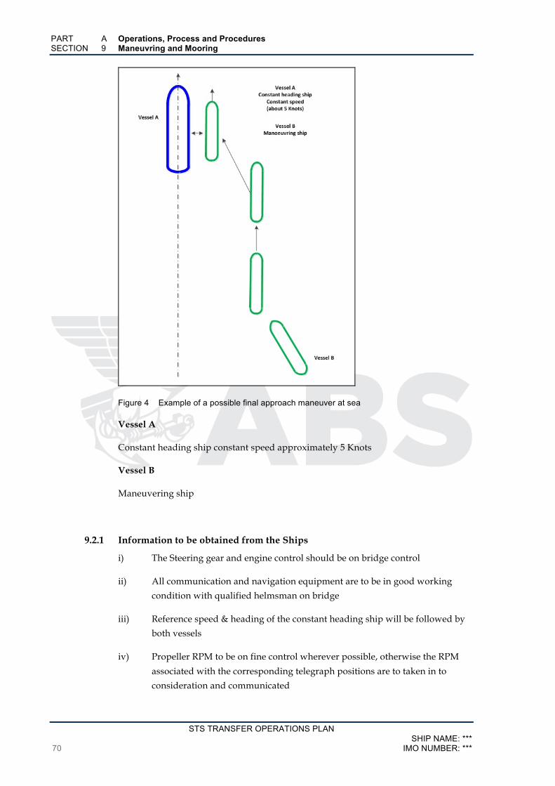
PART A Operations, Process and Procedures SECTION 9 Maneuvring and Mooring
STS TRANSFER OPERATIONS PLAN SHIP NAME: ***
70 IMO NUMBER: ***
Figure 4 Example of a possible final approach maneuver at sea
Vessel A
Constant heading ship constant speed approximately 5 Knots
Vessel B
Maneuvering ship
9.2.1 Information to be obtained from the Ships
i) The Steering gear and engine control should be on bridge control
ii) All communication and navigation equipment are to be in good working
condition with qualified helmsman on bridge
iii) Reference speed & heading of the constant heading ship will be followed by
both vessels
iv) Propeller RPM to be on fine control wherever possible, otherwise the RPM
associated with the corresponding telegraph positions are to taken in to
consideration and communicated
PART A Operations, Process and Procedures SECTION 9 Maneuvring and Mooring
STS TRANSFER OPERATIONS PLAN SHIP NAME: *** IMO NUMBER: *** 71
v) “Number of air start limitations” to be ascertained and well understood by
the bridge
vi) Lighting on deck should be adequate and ship side fenders being lit up
would be preferable
vii) Mooring sides should be confirmed as clear of obstructions
viii) Effective communications ensured. See 7.3 and 7.5
ix) Effective communication between the bridges of both STS ships. Channels
should be separate from each ship’s internal communications
9.2.2 Guidance for Maneuvering Alongside
Items to be considered when maneuvering alongside
i) If the safety of the maneuvering is in question, the Masters or the STS
Superintendent are to immediately abort the berthing operation
ii) The maintenance of a proper lookout is the responsibility of each ship
iii) The optimum approach will be dependent on the maneuvering characteristic
of each ship
Examples of approaches:
• the wind and seas on the port bow of the constant heading ship
• to reduce loads on the fender rigging and the relative wind across the
deck, keeping the wind and swell on the port or starboard quarter of
the constant heading ship
iv) Ensuring that the angle of approach adopted by the maneuvering ship is not
excessive
v) Ensuring that the constant heading ship maintains or adjust its speed as
required by the STS Superintendent or the Master of the maneuvering ship
vi) The effect of ship interaction should be anticipated when maneuvering, the
maneuvering ship’s engines turning to maintain the ahead position
vii) 5 knots or less is the expected maneuvering speed for STS ships conducting
underway operations.
viii) If the maneuvering ship speed is unable to maintain a compatible speed due
to a higher relative speed, then the STS Superintendent should consider
increasing the constant heading ship speed
• It should be remembered that the effects of interaction increase as the
square of the ship’s speed.

PART A Operations, Process and Procedures SECTION 9 Maneuvring and Mooring
STS TRANSFER OPERATIONS PLAN SHIP NAME: ***
72 IMO NUMBER: ***
ix) Due consideration to be given to limitations on load imposed on fender
rigging
9.2.3 Guidance for Maneuvering a Two STS Ship Combination System to Anchorage
i) After having completed mooring, the power and all future maneuvering to
anchor if applicable will be under the power of the constant heading ship
ii) With the constant heading ship under power. The use of unnecessary engine
movements, in particular stern movements should be avoided
iii) Speeds through the water should be minimal
iv) During these times, the former maneuvering ship’s rudder is to be at
amidships and engines stopped
v) The anchor used by the constant heading ship should be on the opposite side
to that of the mooring side
vi) Each STS ship maintaining a continuous navigation watch, watchkeeping
arrangements should comply with the “International Convention on
Standards of Training Certification and Watchkeeping for Seafarers (STCW)”.
See Section 14/4
9.2.4 Guidance for STS Transfers Underway
i) Where the depths of water or other factors restrict the possibility of
anchoring, it may be imperative that STS transfer would be required to be
performed with the ships underway
ii) Such transfers are subject to the availability of adequate sea room, acceptable
traffic, weather forecasts and sea conditions
iii) The STS transfer vessels will be manoeuvred only within the limits of a
designated lightering area
iv) The speed through the water of such STS transfer vessels should be minimal
and relative to the weather conditions
v) A steady course agreed to by both Masters, at slow speed is maintained by
the constant heading ship that normally maintains steerage. The engine RPM
being altered sparingly
vi) There should be a minimum relative movement and turbulence between the
two ships
vii) If the maneuvering ships such as lightering vessels have low speed
maneuvering capability, such ships may be used as the towing ship, with the
requirement of additional backsprings
viii) A safe navigational watch is maintained on both ships.
PART A Operations, Process and Procedures SECTION 9 Maneuvring and Mooring
STS TRANSFER OPERATIONS PLAN SHIP NAME: *** IMO NUMBER: *** 73
ix) If the transfer area is of suitable size, both STS ships may consider drifting
freely
x) If the weather causes the ships to roll unacceptably, engine and rudder
movements may be used to correct the ships heading that would result in
minimum movement
xi) In order to protect fenders and their associated rigging from head-on seas
and swell, it may be necessary to change the heading of the ships to position
the wind and seas off the bow
9.3 Maneuvers with One Ship Already at Anchor i) The ship that anchors will require the Master to take in to account that both
the ships will be held by one anchor, dropped on the side opposite to that of
the mooring side
ii) Also to be considered – water depth, holding ground, winds, currents and
underkeel clearance
iii) Only after a steady heading is reached with the anchoring ship being brought
up to her anchor with the prevailing current and wind conditions, should a
berthing operation be considered
iv) During periods when the tidal stream is to change berthing should not be
attempted
v) If the anchored ship has a tendency to yaw excessively, a tug should be called
in to steady the anchored ship. If a tug is not available the operation is to be
aborted and continued only after steady conditions prevail
vi) To evaluate the necessity of assistance from tugs for the maneuvering ship, a
risk assessment should be undertaken by the organizers
vii) If the current and wind are not from the same direction, the anchored ship
may experience yaw, which may be compounded by the ships having
different drafts and freeboards, which would necessitate the use of tugs to
hold the anchored ship heading during berthing steady
viii) For complex berthing operations, the use of experienced STS Superintendents
may be required
ix) Local port regulations for operations in port may require the use of line
handlers, tugs and pilots
x) Approaches during hours of darkness may require the stationary vessel to
adjust its deck and other background lighting on advice from the
approaching ship

PART A Operations, Process and Procedures SECTION 9 Maneuvring and Mooring
STS TRANSFER OPERATIONS PLAN SHIP NAME: ***
74 IMO NUMBER: ***
9.4 In Port Operations Maneuvers i) A discharging ship may be alongside a terminal or anchored in sheltered waters
ii) Prior to the commencement of maneuvering
• To come alongside another vessel, permission is to be obtained from
the port authority and terminal as applicable
• The appointed STS Superintendent should be made aware of the ETA
of the vessels
• The Master of the moored ship is to be informed of the intended
approach and the Masters are to jointly agree on the procedure.
iii) The port authorities may mandate the use of berthing pilots and the use of tugs
may be mandated depending on the size of the vessel
9.5 Maneuvering with One Ship Already Alongside a Terminal If one or more vessels are moored alongside another ship that is already moored to a
jetty, the operation is called double banking.
If a double banking operation is new to a berth, an engineering evaluation and a
formal risk assessment should be carried out to determine any mitigation measures
that may be necessary and an associated safety plan is to be generated.
Prior to double banking an agreement is to be reached by all concerned parties that at
a minimum the following should be included:
i) Procedures for a safe arrival and departure
ii) Reliability and integrity of the berth and its associated fender
arrangements, fittings for mooring etc. in relation to the anticipated
relevant loads
iii) Safe access for personnel and emergency escapes on both the
concerned vessels
iv) Reliability and adequateness of the operation’s safety management
v) The responsibility and roles of the involved parties
vi) Fire-fighting, emergency un-berthing, planning for contingencies
vii) Availability and need for licensed line handling support
The total displacement of the ship alongside the terminal should be noted by the
Master and if available, the Master may provide crew to receive and secure lines,
provided the safety of other ongoing cargo operations remain unaffected.
9.6 Mooring Operations 9.6.1 Mooring Plans
Most STS service providers may have standard mooring plans. For a specific STS
operation the mooring plan would depend upon:
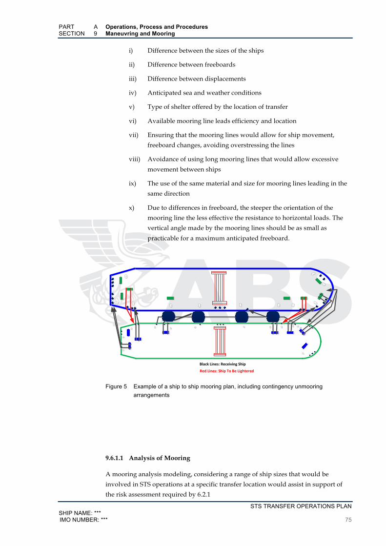
PART A Operations, Process and Procedures SECTION 9 Maneuvring and Mooring
STS TRANSFER OPERATIONS PLAN SHIP NAME: *** IMO NUMBER: *** 75
i) Difference between the sizes of the ships
ii) Difference between freeboards
iii) Difference between displacements
iv) Anticipated sea and weather conditions
v) Type of shelter offered by the location of transfer
vi) Available mooring line leads efficiency and location
vii) Ensuring that the mooring lines would allow for ship movement,
freeboard changes, avoiding overstressing the lines
viii) Avoidance of using long mooring lines that would allow excessive
movement between ships
ix) The use of the same material and size for mooring lines leading in the
same direction
x) Due to differences in freeboard, the steeper the orientation of the
mooring line the less effective the resistance to horizontal loads. The
vertical angle made by the mooring lines should be as small as
practicable for a maximum anticipated freeboard.
BlackLines:ReceivingShip
RedLines:ShipToBeLightered
Figure 5 Example of a ship to ship mooring plan, including contingency unmooring arrangements
9.6.1.1 Analysis of Mooring
A mooring analysis modeling, considering a range of ship sizes that would be
involved in STS operations at a specific transfer location would assist in support of
the risk assessment required by 6.2.1

PART A Operations, Process and Procedures SECTION 9 Maneuvring and Mooring
STS TRANSFER OPERATIONS PLAN SHIP NAME: ***
76 IMO NUMBER: ***
With environmental data for specific regions extracted from metocean studies,
mooring analysis should be conducted for ships in fully laden, partially laden and
ballast conditions.
Based on the mooring analysis the following may be determined:
i) STS operations safe environmental operating limits
ii) The direction and nominal speed at which the ships may proceed, in
relation to:
• Defined prevailing winds
• Sea and swell conditions to limit ship movement and dynamic
loads
• Limiting wear on mooring equipment
• Limiting wear on fenders and ship systems
• Limiting wear on cargo transfer equipment
• Limiting wear on containment structures
iii) Methodology and criteria for aborting transfer operations and
separation of ships.
iv) For maximizing effectiveness the:
• configuration and selection of mooring components
• configuration and selection of rigging fenders

PART A Operations, Process and Procedures SECTION 9 Maneuvring and Mooring
STS TRANSFER OPERATIONS PLAN SHIP NAME: *** IMO NUMBER: *** 77
· LinesshouldonlybeledthroughClassapprovedclosedchocks
· Fullsizemooringbitsandchocksshouldbelocatedascloseasispracticaltotheforwardandaftendsofthemanifold,whilenotinterferingwithsafehosehandlingoperations.
· Additionallinesshouldbereadilyavailabletosupplementmooringsifnecessary,orintheeventoflinefailure.
Figure 6 Typical ship to ship mooring arrangement plan for seagoing tankers
To facilitate mooring and unmooring operations, some operators employ a system
that utilizes a grommet and loop arrangement, sometimes known as a Double D. An
example of this is shown in figure below and includes the optional use of a wire
pennant to prevent chafing damage to the synthetic tail in way of the fairlead. Care
should be taken, when using wire pennants through fairleads that may be used for
High Modulus Poly-Ethylene (HMPE) moorings, to avoid damaging the fairlead’s
surface.
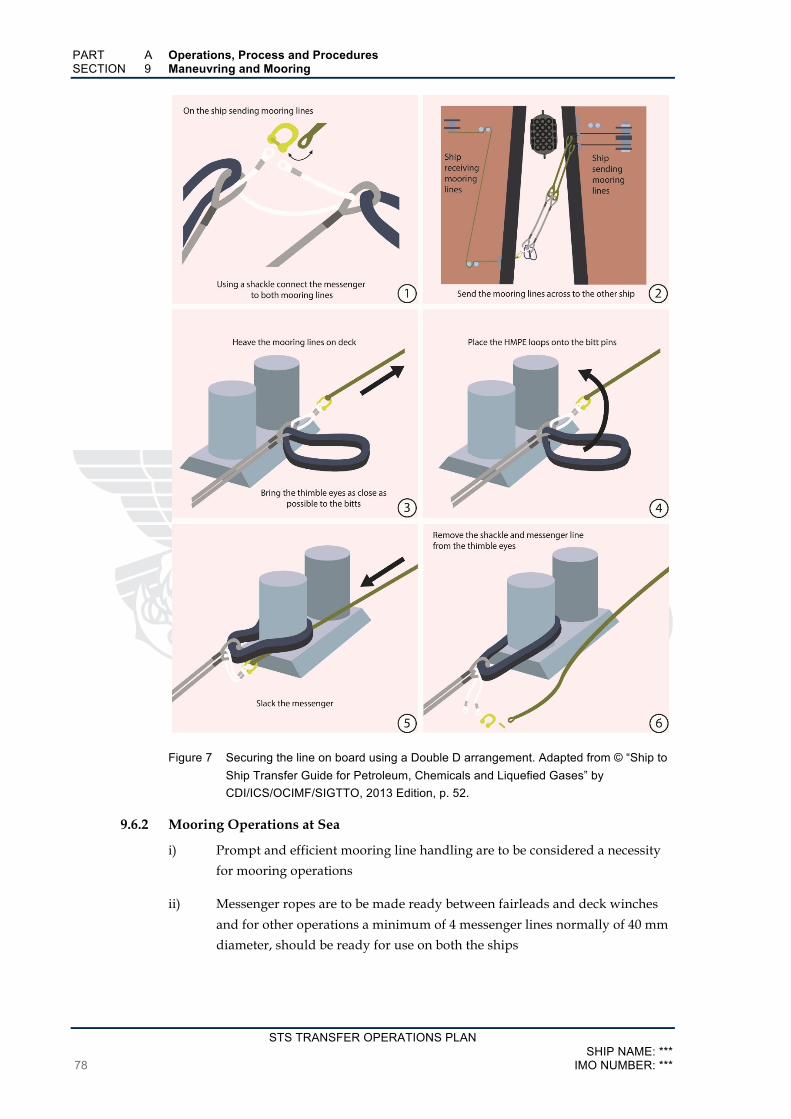
PART A Operations, Process and Procedures SECTION 9 Maneuvring and Mooring
STS TRANSFER OPERATIONS PLAN SHIP NAME: ***
78 IMO NUMBER: ***
Figure 7 Securing the line on board using a Double D arrangement. Adapted from © “Ship to Ship Transfer Guide for Petroleum, Chemicals and Liquefied Gases” by CDI/ICS/OCIMF/SIGTTO, 2013 Edition, p. 52.
9.6.2 Mooring Operations at Sea
i) Prompt and efficient mooring line handling are to be considered a necessity
for mooring operations
ii) Messenger ropes are to be made ready between fairleads and deck winches
and for other operations a minimum of 4 messenger lines normally of 40 mm
diameter, should be ready for use on both the ships

PART A Operations, Process and Procedures SECTION 9 Maneuvring and Mooring
STS TRANSFER OPERATIONS PLAN SHIP NAME: *** IMO NUMBER: *** 79
iii) Moorings should be appropriately rigged to facilitate the safe and effective
line tending when the ships are together. In the event of failure, spare
mooring lines should be readily available
iv) Rope stoppers should be rigged in way of appropriate mooring bits
v) Where appropriate, heaving lines and messenger ropes should be of buoyant
materials
vi) All lines should be led through closed fairleads
vii) Weather conditions may require additional mooring lines, a maximum of 2
mooring lines are to be placed through each chock and secured set of bitts
viii) The mooring plan is to be followed for the rigging of all mooring lines
ix) An agreement is to be made between the ships in respect to the order of
passing mooring lines during mooring, and of releasing lines during
unmooring
x) Quick release mooring arrangements, if used by STS Service providers
should be discussed to ensure proper understanding by the crew
xi) Redundancy should be provided over and above the required mooring lines
determined by a mooring analysis
xii) Where specialized mooring equipment is used, and only where proven, the
number of headlines may be reduced
xiii) The use of ballasting or de-ballasting may be used to reduce the freeboard to
a minimum
xiv) When mooring has been completed, the messengers are to be prepared and
positioned in line with the unmooring plan so as to be readily available in the
event of an emergency situation
xv) After the crew have been warned beforehand and again just before use, non-
pyrotechnic line throwing equipment may be used to make the first
connection
9.6.2.1 Ship to Ship Mooring Systems Efficiency
Tension experienced in mooring lines
Uneven or excessive tension in the mooring lines should be avoided due to the effect
of reducing the weather threshold at which the operating limits are exceeded by the
forces in the mooring lines. Change in the relative freeboards should not be permitted
to cause excessive strain in the mooring lines
Lead angles in mooring lines

PART A Operations, Process and Procedures SECTION 9 Maneuvring and Mooring
STS TRANSFER OPERATIONS PLAN SHIP NAME: ***
80 IMO NUMBER: ***
If the lead angles for the head and stern mooring lines are similar the peak loads can
be minimized and mooring loads effectively shared.
Weather thresholds
Weather thresholds for mooring loads can be accommodated when the mother ship is
fully loaded. However as the mother ship is lightered the weather threshold may
significantly change. Larger mother ships can be expected to have higher weather
threshold for mooring loads.
Waves and Swell with longer periods
Locations subjected to long period waves would necessitate greater caution to be
exercised during STS operations. The load experienced by the mooring lines at a
significant wave height increases excessively with an increase in the wave period.
A greater rolling motion will be experienced with a long period swell. When
planning a turn, caution is to be exercised in long period swells to prevent the
overstressing of moorings.
Direction of wave encounter
During STS operations, wave encounters from a beam direction should be avoided.
STS operations in exposed anchorages, subjected to strong currents, may be exposed
to wind and waves at a large angle.
For STS operations conducted underway, a wave direction from the ships quarter
may be considered as optimum to control mooring loads, the larger ship in the
windward direction. However, for similar sized ships with an increase in the
receiving ship’s displacement, the optimum mooring load wave encounter may
change to the starboard bow, with the receiving ship in the windward direction. A
larger sea room for course alterations across the wind would be beneficial in such
cases.
Mooring arrangement elasticity
To improve the elasticity of mooring arrangements it is beneficial to have 11 meters
long nylon tails, which in certain circumstances would improve the overall integrity
of the mooring system.
Protection from chafing
Cyclical loading due to the vessel’s motion may cause chaffing of the synthetic
moorings that are passed through the shipside fairleads. Suitable lubricated covers
may be used to offer protection to synthetic lines.
9.6.3 Mooring Operations in Port
i) The STS mother ship and vessels expected alongside are to discuss and agree
in advance in the mooring configuration. The crew should be given adequate

PART A Operations, Process and Procedures SECTION 9 Maneuvring and Mooring
STS TRANSFER OPERATIONS PLAN SHIP NAME: *** IMO NUMBER: *** 81
time for preparation of the moorings and understand from which location
and when, the mooring lines are to be sent out
ii) To avoid mooring lines from jumping out of leads, due to vessels coming
alongside to a vessel with a higher freeboard, all mooring lines are to be lead
through closed fairleads
iii) Mooring lines should be passed through fairleads and be secured to bitts,
bollards or cleats with an adequate safe working load (SWL)
iv) As an aid in controlling the approach to a ship that is moored alongside, off-
shore anchors with sufficient length of cable may often be used to provide
the necessary drag force
v) Though vessels installed with bow thrusters may have an advantage in their
use, due consideration should be given to the effects that the use of the
thrusters may have on the mother ship and any other vessels alongside
vi) The first spring lines sent to the mother ship will be followed by the head and
stern lines
vii) If the mooring springs lines are to be used to assist in bringing the vessel
alongside, due consideration must be given to the impact on the mother ship
and the added force being placed on her moorings
viii) Chafing of the mooring lines at the chocks or fairleads of both vessels should
be avoided
ix) Throughout the transfer operation, moorings should be checked and tended
regularly to ensure proper tension
x) The effects of port traffic passing in close proximity to the transfer location
should be taken in to account in the development of a mooring plan.

STS TRANSFER OPERATIONS PLAN SHIP NAME: ***
82 IMO NUMBER: ***
SECTION 10 STS Transfer Operation Procedures Alongside
10.1 Procedures Prior to Transfer On completion of mooring of the two STS ships, before the commencement of cargo,
good communication is to be established between all concerned personnel on both
the ships. All appropriate check list should be completed. See Appendix A, Checklist
4 & 6. Additionally, appropriate pre-transfer safety check lists are to be completed
prior to the commencement of transfer.
10.2 Responsibility for STS Cargo Operations i) A joint agreement on cargo operations is to be reached with the inclusion of
any limitations that may be required to be included by the vessels involved
and the equipment used. Refer to See Subsections 2.3/6.4.4 and Subsection
8.2 for details to be included in a JPO, if applicable
ii) The details of the positively identified responsible persons in charge on each
vessel are to be exchanged. The allocated duties and the identified persons
are normally posted in the ECR, CCR and the bridge with their titles,
locations and allotted duties
iii) Similar lists at the above and other locations are to be posted identifying the
personnel and their duties of all persons involved in emergency situations
iv) As applicable a copy of the ships approved STS Operations Plan is to be
made available on the bridge, ECR and CCR
10.3 Planning for Cargo Transfer Cargo Loading and discharging plans should ensure that the following are addressed:
• Proper stability is maintained
• Hull stresses remain within limits
• Free surfaces and sloshing are considered
• Possible suspension of cargo transfer due to adverse situations
• Verification of operational compliance with damage stability
requirements
• Verification of intact stability and damage stability at planning stage
The plan of the STS cargo transfer operation should be agreed to in writing between
the two ships and, where applicable, is to include the following information:
i) Means of communication
ii) Anticipated duration of operation
PART A Operations, Process and Procedures SECTION 10 STS Transfer Operation Procedures Alongside
STS TRANSFER OPERATIONS PLAN SHIP NAME: *** IMO NUMBER: *** 83
iii) Measures to prevent fatigue, watch or shift arrangements
iv) Grade and quantity of each cargo to be transferred
v) The handling and sequence of grades, cargo density, temperature and
specific precautions such as those that might be necessary for toxic,
flammable and static accumulating products
vi) The supply and compatibility of transfer hoses and equipment,
including insulating arrangements
vii) Cargo system transfer details that should include the number of
pumps and the maximum permissible pumping pressure
viii) Crude Oil washing details and other tank washing details
ix) Cargo heating arrangements
x) Vapor management details
xi) Durations for:
• Discharging
• Starting
• Stopping
• Changing rate of delivery during topping up cargo tanks
xii) Rate of cargo transfer during:
• Initial phase
• Maximum discharging phase
• Topping-off phase
xiii) Stopping and emergency shutdown procedures and signals
xiv) Status of quantity of slops and details of disposal
xv) Procedures for emergencies and spill containment
xvi) Local rules and regulations applicable to the transfer of cargo
xvii) MSDS for the cargo to be transferred and the previous cargo onboard
xviii) Agreement on co-ordination of cargo hose connections, monitoring,
draining and disconnection
xix) Before the start of cargo transfer:
• the discharging ship is to inform the receiving ship the flow rates
for the different phases of cargo transfer of various cargo
• Variations in the transfer rates of cargo required by the receiving
ship or the discharging ship must be intimated to the other vessel
in advance
PART A Operations, Process and Procedures SECTION 10 STS Transfer Operation Procedures Alongside
STS TRANSFER OPERATIONS PLAN SHIP NAME: ***
84 IMO NUMBER: ***
xx) Under no circumstance should the transfer rates exceed the
manufacturer’s specifications of the relevant equipment
xxi) Bunkering during cargo operations is not recommended. However, if
carried out bunkering is to be addressed by a separate Bunkering Plan
with a separate Risk Assessment
10.4 General Guidance on the Transfer of Cargo i) The cargo transfer operation is to be controlled by the receiving vessel as per
the cargo plan
ii) The discharging vessel is to operate to facilitate the requirements of the
receiving vessel
iii) A watch on the cargo manifold areas in way of the hoses is to be maintained
by both vessels
iv) Responsible persons on both vessels are to be in communication and be on
the ready for stoppages in normal statuses and emergencies
v) During the start of cargo transfer at a slow rate, the pipelines are to be
checked for leakage
vi) When the receiving tanks are nearing their final ullage, the agreed topping
off rate is to be adhered to
vii) During the entire transfer, regular checks, at not more than one hour
durations are to made these should include the rate of transfer as measured
on both the vessels and the results logged against time
Any differences should be thoroughly investigated and if need be transfer
operations suspended until the differences are resolved
viii) Transfer rates of cargo should be determined based on:
• Cargo transfer equipment limitations
• Management of inert gas/vapor system limitations
• Limitations of flow velocities in the ship’s fixed cargo piping or
venting systems
ix) Conducting of cargo operations under closed conditions with ullage,
sounding/sampling ports securely closed
x) Prevention of overfilling beyond safe limits and / or prevention of cargo
carryover in to vapor systems, operation of independent high level alarms,
considerations of the impact on vessel’s motion, accuracy of in-tank filling
levels

PART A Operations, Process and Procedures SECTION 10 STS Transfer Operation Procedures Alongside
STS TRANSFER OPERATIONS PLAN SHIP NAME: *** IMO NUMBER: *** 85
xi) Prevention of incorrect operation of pumps and valves, causing pressure
surges. Effective control of pump speeds, in particular when topping off
xii) Compliance with industry codes of practice for cargoes that accumulate static
xiii) Appropriate ballast procedures in accordance with the ship’s ballast water
management plan, to avoid excessive differences in freeboard, excessive
trims and lists
xiv) For at sea operations ensure full maneuverability and propeller immersion
xv) Maintaining a constant watch on mooring lines and fenders to avoid chaffing
and undue stress
xvi) Repositioning of mooring lines and fenders are to be done under strictly
controlled conditions
xvii) Due consideration is to be given to suspend other less important operations
in order to attend the procedures detailed in the STS Operations Plan
10.5 Operational Guidance after Completion of Cargo Transfer i) Cargo transfer equipment and vapor hoses etc. to be properly drained prior to
disconnecting
ii) Equipment for Cargo transfer to be disconnected and securely blanked
iii) Cargo manifolds to be securely blanked
iv) Where applicable, authorities should be informed of completion of cargo
transfer and the anticipated time of unmooring
STS TRANSFER OPERATIONS PLAN SHIP NAME: ***
86 IMO NUMBER: ***
SECTION 11 STS Transfer Operation Unmooring
11.1 Prior Unmooring Preparations i) Prior to unmooring, Checklist 5 in Appendix A is to be completed by each
vessel
ii) On completion of Checklist 5 confirmations are to be exchanged between the
vessels, confirming that all the check items have been checked to their
satisfaction
iii) The respective teams on bridge and the officers on the mooring stations on
both the vessels are to clearly understand the sequence to be followed and
the methodology line releasing.
iv) Where applicable, a broadcast is to be made on the appropriate VHF
channel(s) alerting all vessels in the vicinity, requesting a wide berth during
the duration of unmooring maneuvers
11.2 Procedure for Unmooring Considering the possibility of the risk of steel to steel contact during maneuvers
associated with vessel separation, a successful and event free unmooring requires
careful planning and execution.
11.2.1 Unmooring after Underway Transfer
i) For ships that have carried out STS transfers underway consideration may be
given to:
• The combination of the two ship system is positioned so that the ship
with the highest freeboard is on the downwind side
• For conditions where there is negligible wind, the combination of the
two ship system is positioned so that the swell is ahead to assist with
the separation of the bows
ii) Proportional to the weather conditions:
• Speeds are to be maintained at a minimum
• The sequence of mooring line release for each individual mooring
operation
iii) Moorings are to remain on the winch brake until such time the Master
instructs the crew to place the winch in gear
iv) The sequence of unmooring is to ensure that the propellers are kept clear
v) Of high importance throughout the duration of unmooring the tension in the
mooring lines and the compression of individual fenders should be
monitored

PART A Operations, Process and Procedures SECTION 11 STS Transfer Operation Unmooring
STS TRANSFER OPERATIONS PLAN SHIP NAME: *** IMO NUMBER: *** 87
vi) As the bows open up, the proximity of the aft ends of both vessels and
compression on the aftermost fender should be monitored closely
vii) The maneuvering ship should avoid crossing close ahead of the other ship
viii) Until the maneuvering ship advises the constant heading ship that it is clear,
the constant heading ship should not independently carry out maneuvers
ix) If local conditions or ship configurations do not permit the separation of the
two vessels other alternative means may be considered
11.2.2 Unmooring with one Ship at Anchor
i) During a change in the tide and/or yawing, unmooring should not be carried
out when one ship is at anchor
ii) Unmooring when one ship is anchored should only be carried out by highly
experienced personnel in STS operations
iii) Where the ship is not fitted with thrusters and where yawing of the anchored
ship is anticipated, either tug support is to be requested or the unmooring
operations are to be suspended
iv) Alternatively, and if possible the anchor should be weighed and unmooring
carried out while making way
v) On completion of singling-up, appropriate controlled slackening of the head
and stern lines may allow the vessel to part from the anchored ship
vi) Main engine, thrusters and rudder movements should be used cautiously
taking in to consideration the effect on the heading of the anchored ship and
avoiding any initiation to cause yaw
11.2.3 Unmooring from a Ship alongside a Terminal
i) Permission is to be obtained from the harbor authorities and the terminal
prior commencement of unmooring
ii) Unmooring operations are to be in accordance with the procedures agreed to
by both Masters
iii) Due consideration is to be given to prevailing tidal and weather conditions
iv) In the case of multiple vessels alongside a mother ship, the STS
Superintendent should give his consent for the unmooring operation and all
other vessels should be made aware of the planned departure
v) During hours of darkness if unmooring is to take place, consideration is to be
given to reduce background lighting to enable full awareness of the
proximity to navigational hazards and other vessels. However, working
areas are to be adequately lit

PART A Operations, Process and Procedures SECTION 11 STS Transfer Operation Unmooring
STS TRANSFER OPERATIONS PLAN SHIP NAME: ***
88 IMO NUMBER: ***
vi) Local regulations may require the use of tug support within port limits
vii) Vessels fitted with bow and stern thrusters are to be mindful of the effects of
their use on vessels in the vicinity. However, they are to be used to the full
advantage of maneuvering where possible
11.2.4 Unmooring with the use of Quick Release Arrangements
i) The lines are to be released in an orderly, prompt and efficient and safe
manner
ii) The use of the engines for maneuvering on either vessel should not be
hindered even in emergencies
iii) Advanced planning is required for such operations which require good
communications and supervision
iv) The methodology may vary from one operation to the other:
• The use of quick release hooks secured around the mooring bits
• A toggle pin used in conjunction with a messenger to take the load on
the mooring line while it is removed from the mooring bit
• Moorings attached to quick release hooks should not be released when
under load and the lines should be slacked down prior to release

PART A Operations, Process and Procedures SECTION 11 STS Transfer Operation Unmooring
STS TRANSFER OPERATIONS PLAN SHIP NAME: *** IMO NUMBER: *** 89
Figure 8 Unmooring with toggle pins with Double-D tails installed. Adapted from © “Ship to Ship Transfer Guide for Petroleum, Chemicals and Liquefied Gases” by CDI/ICS/OCIMF/SIGTTO, 2013 Edition, p. 67.

STS TRANSFER OPERATIONS PLAN SHIP NAME: ***
90 IMO NUMBER: ***
SECTION 12 STS Transfer Operation Equipment
12.1 Fenders 12.1.1 Fenders Associated with at Sea Transfer Operations
Fenders for offshore STS Transfer Operations use two categories of fenders - Primary
and Secondary.
Primary fenders
i) Primary fenders are positioned at the ends of the parallel mid-body with the
remaining fenders placed on either side of the manifold area
ii) They should be so positioned that they are clear from the manifold area
iii) Primary fenders are usually of the pneumatic type, manufactured, tested and
maintained to an ISO standard 17357. See Section 14/14
• ISO 17357 specifies the material, performance, and dimensions of low-
pressure floating pneumatic rubber fenders, which are intended to be
used for the berthing, and mooring of a ship to another ship or
berthing structure. It also specifies the minimum test and inspection
procedures for floating low-pressure pneumatic rubber fenders
• ISO 17357 does not address the methods for selecting the correct
fender type or any safety hazards associated with its use
iv) Lightering operation involving transfers to multiple vessels may find it
preferable to rig the primary fenders on the discharging ship. This may result
in less handling of the fenders, and this methodology should be evaluated
during the risk assessment performed for the operation
Secondary Fenders
i) Secondary fenders are positioned to protect the ship’s plating around the
bow and stern areas
ii) Secondary fenders may be constructed as pneumatic type or foam Filled type
If foam, filled type are to be used:
• ISO Standards may not be appropriate for their manufacture and
testing
• However ISO 9000 or a similar standard may be used for materials,
inspection or verification
• ISO 9000 is a set of international standards on quality management
and quality assurance developed to help companies effectively
document the quality system elements to be implemented to maintain

PART A Operations, Process and Procedures SECTION 12 STS Transfer Operation Equipment
STS TRANSFER OPERATIONS PLAN SHIP NAME: *** IMO NUMBER: *** 91
an efficient quality system. They are not specific to any one industry
and can be applied to organizations of any size
iii) They are so positioned to prevent inadvertent contact caused due to
misalignments during the phases of mooring and unmooring
iv) The areas which are considered as most likely to be exposed to such
inadvertent contact are the ship side where the parallel body curves towards
the bow and the stern
v) The ship with the lower freeboard will determine the height above the
waterline of the secondary fenders
vi) Prior to commencement of the operation, positioning of the secondary
fenders should be determined based on the difference between the
freeboards of the two vessels
vii) Prior to the final approach, the discharging ship should make a visual check
and confirm that the secondary fenders are in appropriate positions
viii) The primary fender towing line may be in close proximity with the
secondary fender and may pose a risk of interference in the arrangement
ix) To prevent the risk of a secondary fender inadvertently suddenly boarding,
adequate measures are to be taken by the personnel involved.
x) To prevent inadvertent interference, the height of the secondary fender
should be constantly monitored and adjusted accordingly
xi) Portable chocks may be supplied by STS Service providers in case of the
absence of fairleads and securing points at locations where they may be
required for the positioning of secondary fenders
xii) The height of the secondary fenders is to be adjusted during the transfer
operation
xiii) Due to changes in the freeboards of the ships the height of the secondary
fenders may be required to be adjusted if the likely points of contact between
the ships have changed
xiv) Secondary fenders should preferably be light in weight since:
• Frequently they have to be hauled well above the water line.
• They may be located in positions with limited access to lifting gear or
support points
• They may have to be moved quickly at short notice to prevent
inadvertent contact

PART A Operations, Process and Procedures SECTION 12 STS Transfer Operation Equipment
STS TRANSFER OPERATIONS PLAN SHIP NAME: ***
92 IMO NUMBER: ***
12.1.2 Other Considerations Associated with Fenders for at Sea Transfer Operations
i) STS Service providers usually have support craft to assist in the
positioning of fenders if the STS transfer is not being performed by
using a dedicated ship.
ii) In general, Fenders may be placed on either ship based on the
completion of a review of the available mooring points and fairleads to
accommodate the fender pennants
iii) Fenders installed on the maneuvering ship would mitigate the
probability of landing on an unprotected hull section
iv) Fender towing wires may be subject to greater stresses when rigged on
the maneuvering ship
v) Maneuvering ships being the smaller of the two STS ships a lesser
latitude for rigging is available
vi) To prevent overstressing fender arrangements, operations should be
performed with limitations on speed
vii) Pennants for fenders may be secured on to a winch mounted wire or
made fast to a mooring bit -
• If shackled on to a winch mooring wire, the brake is to be
appropriately applied to avoid rendering which would result in
the fender string moving out of position
• If secured on a split drum mooring winch, the proper number of
turns should be taken on the tension side of the winch, ensuring
effective and firm brake holding power
viii) Fenders should not be secured on shell plating recessed bits due to the
probable inadequacy of safe working load.
ix) To prevent snagging, fenders should be kept clear of recessed bits and
pilot doors located on either vessel’s hull (if applicable.)
Position and method of Securing Fenders
i) In advance of the STS operation, the STS Superintendent advises the
ships of the position and method to be used for securing fenders
ii) The method followed for fender pennants to be lead through fairleads
should ensure that chaffing does not occur in way of fishplates and
other obstructions

PART A Operations, Process and Procedures SECTION 12 STS Transfer Operation Equipment
STS TRANSFER OPERATIONS PLAN SHIP NAME: *** IMO NUMBER: *** 93
Fenders Rigged in a Continuous String
Back-uppennant
Primarypennant(TowingLine)
Spacingline TailLine
Figure 9 Fenders Rigged in a Continuous String
Figure 9 indicates primary fenders positioned one at each end of the parallel body
and similar additional fenders fitted in-between. The fender string may be made up
to a prearranged length.
Fenders Rigged in Pairs
Back-uppennant
Primarypennant(TowingLine)
Spacingline TailLine
TailLine
Permanentpennant(TowingLine)
Figure 10 Fenders Rigged in Pairs
Figure 10 indicates the same four fenders grouped in two pairs. In this case each pair
is placed well forward and well aft of the parallel body offering better protection.
12.1.3 Guidance for Fender Selection for at Sea Transfers
For guidance on the selection of at sea transfers reference should be made to
Subsection 9.1.2 of the reference documents in Section 14/1
“CDI/ICS/OCIMF/SIGTTO “Ship-to-Ship Transfer Guide for Petroleum, Chemicals
and Liquefied Gases’, 2013 (STS Guide)” of this document.
12.1.4 Requirements for Fenders
i) The selection process of fenders will depend on the forces that will be
generated between ships
ii) Consideration is to be given to the energy absorption capability and the
capability of maintaining a sufficient stand-off distance such that the
compressed diameter will not permit contact between the ships structures
caused by rolling when the vessels are alongside
PART A Operations, Process and Procedures SECTION 12 STS Transfer Operation Equipment
STS TRANSFER OPERATIONS PLAN SHIP NAME: ***
94 IMO NUMBER: ***
iii) During inclement weather, to prevent inadvertent boarding of the fender, the
diameter of the fender is to be chosen so that it is less than half the freeboard
of the ship
iv) Fenders are normally fitted with hard wearing tires and cage components
may be fitted with rubber sleeves to reduce abrasion damage to the outer
rubber of the fender and to ensure that steel-to-steel contact does not occur
between the fender cage and the ship’s hull
v) To improve their visibility during hours of darkness retro-reflective tape is
installed on fenders
vi) Fenders are subjected to regular inspection for deterioration or damage, the
pressure is to be regularly checked, safety valves inspected in accordance
with the manufacturers recommendations. Inspection and testing records are
to be maintained
vii) Factors influencing the life of fenders:
• Method of storage
• Standards of maintenance
• Manufacturers recommended service life, typically 15 years
viii) Before selection for use - the age of the fender should be ascertained,
inspection of detailed history reports that would include the particulars of
each job they were used for, the regiment of inspection, testing, maintenance
and casualty information
ix) Selection of fenders should consider – manufacturers specification indicating
the combined berthing displacement, approach velocity, sea and swell
conditions
12.1.5 Fenders Associated with at Port Transfer Operations
i) The approach velocity and energy absorption requirements in the estimated
prevailing conditions are to be taken in to account to ensure that ships
performing STS operations in port are adequately fendered
ii) Preferably a risk assessment is to be performed in accordance with the
guidance in Subsection 12.1.3
iii) Specific trades in some regions of the world may provide fenders in
accordance with local customs and practices. It is expected of Masters to
reject any vessel considered to have unacceptable fendering arrangements
which are found inadequate or pose the risk of metal-to-metal contact
PART A Operations, Process and Procedures SECTION 12 STS Transfer Operation Equipment
STS TRANSFER OPERATIONS PLAN SHIP NAME: *** IMO NUMBER: *** 95
iv) Vessels that are larger in size may have primary fenders that are either foam
filled or pneumatic. Masters should have a clear understanding of the
number and dimension of fenders required
v) Prior to maneuvering, primary fenders should be in place and secured.
Secondary fenders for protection of the bow, stern and accommodation
should be readily available for the crew to position as required to prevent
contact of the vessels
12.1.6 Low Pressure Fenders
i) Though not normally used for at sea STS transfers, Low Pressure (L.P.)
fenders may be used in emergencies due to their ease of transportation
ii) The sizes of LP fenders may vary up to 4.5 meters diameter and lengths up to
30 meters
iii) Comparisons between H.P. fenders and L.P. fenders
• H.P. fenders have initial pressures of 50 or 80 kPa (500 or 800 mbar)
compared to L.P. fender pressures of 7 kPa (70 mbar), which rises to a
maximum of ‘around 100 kPa (1,000 mbar) when compressed
• Even though LP fenders have an equivalent energy absorption and
stand-off characteristics when compared to HP fenders, they are
approximately half the weight of their HP counterparts, but are
significantly longer
• L.P. fenders are more susceptible to damage and abrasion when
compared to H.P. fenders
iv) In L.P. fenders high localized loads are potentially minimized as they
provide a soft cushion effect whereby energy can be absorbed across a large
contact area. This feature may have extensive use when offloading damaged
vessels
v) Deflated L.P. fenders may be rolled and folded and are light weight which
affords ease of transportation.
However when inflated they may be difficult to handle due their physical
size
vi) Considerations are to be carefully given to changes in atmospheric pressure
and ambient temperatures when inflating L.P. fenders
12.1.7 Ribbed Fenders
i) Though Ribbed fenders may have similar dimensions, pressure ratings and
energy absorption characteristics compared to HP fenders, Ribbed fenders
may not be generally used as primary fenders in exposed locations

PART A Operations, Process and Procedures SECTION 12 STS Transfer Operation Equipment
STS TRANSFER OPERATIONS PLAN SHIP NAME: ***
96 IMO NUMBER: ***
ii) Though Ribbed fenders are lighter than equivalent sized caged H.P. fenders,
they do not provide an equivalent degree of protection
iii) Though ribbed fenders may have the same materials used for complying
with ISO 17357, they are not compliant with entire standard due to the ribs
provided
12.1.8 Foam Filled Fenders
i) In exposed locations Foam filled fenders are not commonly used as primary
fenders. They may find use in port operations or in sheltered waters
ii) Foam filled fenders have a foam core that is closed celled, that is covered by a
flexible protective skin. Should the outer cover be damaged, the foam core
results in the fender retaining buoyancy
iii) Protective cages may be provided for Foam filled fenders
iv) For the absorption values of Foam filled fenders reference may be made to
Appendix H of Section 14/1 “CDI/ICS/OCIMF/SIGTTO “Ship-to-Ship
Transfer Guide for Petroleum, Chemicals and Liquefied Gases’, 2013 (STS
Guide)” of this document
12.2 Cargo Transfer Hoses 12.2.1 Standards for Hoses
STS transfer operations should be performed by the use of specially designed and
constructed hoses for the product being handled. To ensure that they are fit for their
intended use, a detailed check is to be made at the time of their issuance.
Standards such as EN1765 for oil service may be referred to for acceptability. Since,
presently, it is difficult to enforce an international standard, a technical justification
being hard to determine, until such time an international standard is available, the
following attributes may be considered for such semi-continuous hoses:
i) Incident free service over many years
ii) Ease of handling
iii) Kink tolerance
iv) Independent evaluation supported with an appropriate hazard review
to ensure they are safe for the specific operation
The electrical properties of transfer hoses may be continuous or discontinuous, which
is dependent if an insulation flange is used or not:
i) Where an insulation flange is used the hose string may be electrically
continuous
PART A Operations, Process and Procedures SECTION 12 STS Transfer Operation Equipment
STS TRANSFER OPERATIONS PLAN SHIP NAME: *** IMO NUMBER: *** 97
ii) Where an insulation flange is not used a single length of hose in the
hose string is to be electrically discontinuous
Before transfer hoses are assembled, a detailed inspection is to be carried out. If any
damage to a hose or a flange is observed to be critical, the hose should be withdrawn
from service.
12.2.2 Length of Hoses
The special characteristics of the STS vessels would determine the length of hoses to
be used. The length of hoses selected may be dependent on the following:
i) Distance between manifold and ship’s side
ii) Distance horizontally between the vessels
iii) The offset of the manifolds (Difference in fore and aft alignment)
iv) Horizontal and vertical movement
v) Estimated relative change in the manifold heights between the vessels
vi) Minimum allowable bend radius of the hose
vii) Hoses used in the hose string to be the minimum possible
viii) Limitations of the ship’s equipment and/or other hose handling
requirements
ix) Other special characteristics related to the specific vessels
12.2.3 Flow Velocities and Pressure Ratings of Hoses
The pressure ratings of hoses should be determined based on its intended service.
Flow velocity maximums are determined and limited by their construction. The hose
manufacturer’s recommended flow rates/velocities/pressure ratings should be
identified in the manufactures certification and these values should never be
exceeded.
The relationship between the flow velocity through a hose and flow rate can be
determined by the formula:
Q = 3600 � r2 v
where
q : Flow rate, m3/hour
r : Internal radius, m

PART A Operations, Process and Procedures SECTION 12 STS Transfer Operation Equipment
STS TRANSFER OPERATIONS PLAN SHIP NAME: ***
98 IMO NUMBER: ***
v : flow velocity, m/s
Due consideration should be given to other limitations on flow, imposed by other
components or equipment such as valve linings.
12.2.4 Hose Handling
Damage or reduction in service life due to kinking and over-stressing of hose strings
must be avoided by exercising proper care when handling and supporting.
The aforementioned caution may include consideration of the minimum bending
radius (MBR).
MBR = Nominal Bore × 6
Hoses in excess of 300 mm in diameter would be progressively more difficult to
handle.
Limitation on hose sizes may be required by the capabilities of the onboard lifting
equipment and manifold construction.
Before each transfer operation, the tightness of all interconnecting flanges in a hose
string is to be rechecked.
Consideration is to be given to the OCIMF guidelines to ensure that cargo transfer
equipment is supported by suitable means to prevent excessive loads on manifolds.
The supports for hoses forms an essential part of the load restraint system,
preventing excessive axial and torsional loads on the cargo hose end fittings. Their
design load and reliability should be considered along with their ability to prevent
chafing of the hose(s), avoidance of damage to handrails and other fittings in the
event of separation of an emergency release coupling (ERC), where fitted.
Furthermore, their design should ensure electrical isolation between the hose and the
ship’s structure.
12.2.5 Connection of Hoses
i) To ensure leak-tight connections, flanges and quick connect/disconnect
(QC/DC) couplings should be in good condition and properly secured
ii) The cargo to be transferred would determine the material of gaskets to be
used
iii) The connections for hoses are to be performed by the crew from both ships
iv) QC/DC couplings may be used to connect transfer hoses to the ship’s
manifold:

PART A Operations, Process and Procedures SECTION 12 STS Transfer Operation Equipment
STS TRANSFER OPERATIONS PLAN SHIP NAME: *** IMO NUMBER: *** 99
• The coupling provides a quick and effective method of making the
connection
• The flanges to be joined are brought together and are positioned
within the cam blocks around the coupling
• Using a short length of bar, the cams are then rotated to secure the
coupling
• An internal ‘O’ ring provides a seal within the coupling.
12.2.6 Inspection of Hoses and Testing
i) A visual inspection of hoses is to be performed prior to their use
ii) Valid test certificates should be examined to confirm that the hoses supplied
by the STS Service provider are fit for the intended service
iii) Regular inspection of hoses for damage or deterioration is to be carried out
iv) Manufacturer’s recommendation, standard of manufacture, local regulatory
requirements would specify the testing regimen for testing
v) The record of inspections should be examined
vi) Hydrostatic pressure tests, assessment of temporary and permanent
elongation, electrical continuity should be periodically tested at intervals not
exceeding 12 months
vii) The hose manufacturer’s guidance on the criteria to be used for the
retirement of hoses should be available
12.2.7 Marking
The information required by the appropriate international standard and other
applicable regulations should be permanently marked on each transfer hose:
i) The identification of the standard specification for the hose
manufacture
ii) The maximum allowable working pressure
iii) Manufacturer’s serial number
iv) Month and year of manufacture
v) Electrical Characteristic of the hose-electrically continuous, electrically
discontinuous or semi-continuous.
vi) Intended type of service
vii) The hose manufacturer’s name or trade mark

PART A Operations, Process and Procedures SECTION 12 STS Transfer Operation Equipment
STS TRANSFER OPERATIONS PLAN SHIP NAME: ***
100 IMO NUMBER: ***
12.3 Equipment for Mooring Mooring equipment on ships involved in STS transfer operations should be reliable
and of good quality.
The following is a non-exhaustive list of mooring equipment for which adequate
attention is to be given:
i) Mooring lines and messengers are to be of good quality
ii) The operation of winches is to be efficient
iii) Closed fairleads of sufficient strength are to be used
iv) Bollards and other associated equipment are to be of sufficient
strength
v) Regular tested winch brakes are of high importance
vi) Bollards and fair leads are to be sized and marked and certified in
accordance with Section 14/3 OCIMF’s Mooring Equipment
Guidelines.
vii) Enclosed type of fairleads ensure effective control of mooring lines as
the freeboards of the two ships changes
viii) Fairleads are to be proportioned large enough to permit the mooring
line (plus any soft rope tail and shackle) to pass through comfortably
ix) Ships equipped with steel wire or high modulus synthetic fiber
mooring lines are to be installed with soft rope tails to provide
elasticity and permit cutting away in the event of emergency.
Provisions for making an axe available should be made to facilitate
cutting soft rope tails in an emergency.
x) Rope Tails:
• At least 11 meters long
• Have a dry breaking strength of at least 25% more or 37% more
for polyamide(nylon) than the lines to which they are attached
• Connection between the soft rope tail and the wire rope should be
made with an approved fitting- Mandal, Tonsberg or Boss shackle.
• Subject to manufacturers recommendations to ensure minimum
bend radii, a cow hitch may be used for attaching tails to high
modulus synthetic ropes
• Vessel’s that are frequently involved with STS operations may
have different lengths of rope tails than the standard 11 meters.
Furthermore, they may be fitted with wire pennants. Caution is to
be exercised to prevent such arrangements from being used

PART A Operations, Process and Procedures SECTION 12 STS Transfer Operation Equipment
STS TRANSFER OPERATIONS PLAN SHIP NAME: *** IMO NUMBER: *** 101
through fairleads which normally have synthetic ropes passing
through as the wire ropes may cause grooving on the surfaces of
the fairleads, these grooves damaging the fairleads that
subsequently pass through
xi) Fairleads:
• For large vessel of 160,000 DWT and other similar vessel the full
sized bits and closed fairleads should as far as practicable be as
close as possible to the forward and aft end of the manifold, to
take on the spring lines from the smaller vessel
• To prevent chaffing, larger ships should not utilize fairleads that
are located on the transom stern
• The minimum number of closed fairleads on larger ships is
normally 3 forward and 4 aft
• For ships not fitted with special mooring arrangements normally
the configuration would be 6 headlines, 2 forward and 2 back
springs and 4 stern lines
• The number of headlines could be reduced to 4 if specialized
mooring equipment is used with reliable operating environment
proven for the operation
xii) • Aft fairleads are to be located as far aft as practical
• Forward fairleads are to be located as close as possible to the
centerline
• Forward fairleads should be clear of any anchor housing
protrusion
• For the location of fairleads, consideration is to be given to
achieving a mooring arrangement that allows mooring lines of the
same function as
◦ Head lines ◦ Stern lines ◦ Breast lines ◦ Springs
• To run as parallel as possible to each other with the purpose of
effectively sharing the load
• The bitts associated with closed fairleads should have the same
SWL
• Each set of bitts should be arranged for safe use of messengers
and attendant winches.
• Provisions are to be arranged for securing fender lines

PART A Operations, Process and Procedures SECTION 12 STS Transfer Operation Equipment
STS TRANSFER OPERATIONS PLAN SHIP NAME: ***
102 IMO NUMBER: ***
12.4 Transfer of Personnel – STS transfer Operations at Sea The transfer of personnel between ships should be kept at an absolute minimum. The
safest means of transfer should be determined by a risk assessment based on the
prevailing conditions and circumstance at the time and place of the proposed transfer.
The risks associated with such transfers are to be compared with the risks associated
with other means of transfer that may be available.
The following are non-exhaustive items that are to be considered:
i) The use of gangways should only be considered in sheltered locations,
where the movement of vessels is little or absent. Gangways should be:
• Light weight insulated type
• Fitted with rails
• Installed with a safety net
• Should not be of the open rung type ladders
• Should always be tended to, ensuring that they remain safe at all
times and within the safe design operating parameters
ii) Where transfers are accomplished by the use of workboats with the
use of appropriate pilot ladders and /or accommodation ladder
combinations, due consideration is to be given to:
• The freeboard of the ships
• Suitability of the workboat
• Experience of transfer personnel
• Fitness of transfer personnel
• The combination ladder should be rigged in accordance with
Section 14/18 “Shipping Industry Guidance on Pilot Transfer
Arrangements”
iii) Prior to using a Personnel Transfer Basket PTB, it should be confirmed
that:
• The PTM is suitable and fit for purpose
• The PTB is certified, tested and inspected
• The associated lifting equipment is suitable for lifting and
transferring personnel with adequate procedures in place
• Refer to Appendix C/ Checklist 8
iv) Factors for consideration prior selection and commencement of
transfer option:
PART A Operations, Process and Procedures SECTION 12 STS Transfer Operation Equipment
STS TRANSFER OPERATIONS PLAN SHIP NAME: *** IMO NUMBER: *** 103
• Consideration of relevant Codes, national or local Regulations
that relate to transfer of personnel
• Personnel involved in the transfer operation should be
appropriately trained and familiar with the risk assessment
• Transferring personnel should wear personal floatation devices
(PFD)
• Personnel operating any lifting equipment or working in the
vicinity of the transfer area should mandatorily wear personal
protective equipment PPE
• Personnel involved in the transfer operation should be
appropriately trained and familiar with the risk assessment
• The ship’s Master or a senior deck officer should supervise the
transfer operation
12.4.1 Lifting Equipment Suitability
The following are non-exhaustive items that are to be considered for the selection of
the ship’s lifting equipment and PTB’s:
i) The use of derricks should never be an option
ii) If cranes are to be used:
• They should be adequately equipped with safety devices for
preventing free falls
• Hoisting and lowering limiters are to be used and addressed in a
risk assessment
• Means are to be provided for the safe recover of personnel being
transferred in the event of power or control system failure
iii) In general all lifting equipment should be:
• Inspected, load tested, maintained and certified (including PTBs,
rigging & strops)
• The ship’s planned maintenance should include lifting equipment
• Class documents and load certifications are to be readily available
for inspection
iv) For lifting equipment used for personnel transfer, the maximum
permitted load should be clearly identified and include an additional
safety factor
v) Hooks or shackles should be appropriately closed and moused or
wired

PART A Operations, Process and Procedures SECTION 12 STS Transfer Operation Equipment
STS TRANSFER OPERATIONS PLAN SHIP NAME: ***
104 IMO NUMBER: ***
vi) Lifting equipment should have adequate reach to the safe landing area
while simultaneously maintain a vertical lift. Consideration should be
given to fender diameter and the freeboard together with the
minimum and maximum of the crane boom’s angles
vii) Provisions are to be arranged for the most effective method of
communication between
• The signalman,
• The equipment and
• The personnel in the basket
vii) Prior to commencement of operations, a thorough evaluation is to be
made. The following should be points for consideration:
• Restricted mobility and visibility for personnel using PTB’s
restricting their ability to use hand signals or operate radios
• In order to maintain an effective control of operation, signalmen
are required to keep the basket and equipment controller in full
view at all times
• Appropriate noise level codes are to be complied with. For audio
communications, the ambient noise from other machinery should
be anticipated such as hydraulic machinery, the wind etc.
• Proper training in the procedures to be followed should be given
to personnel that are to use the PTB’s
• Similarly, operators are to be trained in using equipment for
personnel transfer. In addition to classroom training, the training
is to include simulated dummy loads, wherein transfers are
practiced until the operation can be completed with minimal risk
• A simulated transfer should be exercised before the
commencement of the first transfer
• The operation of personnel transfers are to be accomplished by
the load under full control in both modes lowering and hoisting,
the transfer basket being raised just high enough to clear any
obstacles with the minimum of swinging
• Provisions for assistance by trained personnel should be available
• During personnel transfers, foreseeable emergencies should be
met with well-developed contingency measures
• Specifications for new constructions should include lifting
equipment that is certified for man-riding – Refer to The ABS
Guide for Certification of Lifting Appliances
PART A Operations, Process and Procedures SECTION 12 STS Transfer Operation Equipment
STS TRANSFER OPERATIONS PLAN SHIP NAME: *** IMO NUMBER: *** 105
12.5 Transfer of Personnel – STS transfer Operations in Port i) During double banked transfers, personnel may need to traverse the vessel
alongside to access the terminal
ii) A formal risk assessment is to identify the safest means of personnel transfer
between vessels
iii) If the use of the gangway is considered appropriate, a safety net must be
rigged
iv) If a pilot ladder is considered safe, it should be rigged from the higher
freeboard vessel to the deck of lower freeboard vessel
v) If the difference in freeboards or the distance between vessels is too great, a
launch may have to be used
vi) PFD’s should be worn, lifebuoy to be ready for use, supervision is to be by a
responsible officer
12.6 STS transfer Operations Lighting Lighting used for STS transfers at night may have the following considerations:
i) The normal in-port deck lighting may be adequate in most situations
ii) Manifold areas, work areas and personnel access points should be well
lit
iii) Deck lighting should be such that it does not interfere with
maintaining an effective lookout and/or impair the ship’s navigation
signals and lights
iv) In the instance of a close quarter situation with an STS transfer
operations shutdown, the deck lighting may need to be shut off
v) In hazardous areas, portable spotlights may be used
vi) Bridge wing searchlights are useful in night mooring and unmooring
operations
12.7 STS transfer Operations Ancillary Equipment Equipment associated with the handling, securing and/or support of primary and
secondary fenders, cargo transfer hoses, and support craft are to be inspected prior to
commencement of the STS transfer operation. A suitable retirement criteria is to be
established.
12.8 STS transfer Operations Noise Levels Excessive noise levels may:
PART A Operations, Process and Procedures SECTION 12 STS Transfer Operation Equipment
STS TRANSFER OPERATIONS PLAN SHIP NAME: ***
106 IMO NUMBER: ***
i) Have a detrimental effect on the safety of operational communications
ii) May affect off-duty personnel’s periods of rest, thereby contributing to
fatigue
Mitigation measures may include
i) Assessment of noise levels and the application of appropriate
measures to minimize disruption
ii) The adoption of alternative sleeping arrangements for affected crew
members
Refer to the “ABS Guide for Crew Habitability on Ships”.
STS TRANSFER OPERATIONS PLAN SHIP NAME: *** IMO NUMBER: *** 107
SECTION 13 STS Transfer Operation Emergencies
13.1 Emergency Response Procedures & Contingency Planning The adherence to proper procedures and the use of suitable equipment facilitate in
maintaining Ship to ship transfer operations safely.
However, the risk of accidents with the potential scale of the consequences,
necessitate the requirement for vessel operators and organizers to develop
contingency plans for dealing with emergencies.
The ship’s safety management system (SMS) and its STS plan is to include ship
specific contingency plans covering a possible range of emergency scenarios
A risk assessment is to be carried out for all STS transfer operations as identified in
6.2.2 of this plan. The risk assessment is to identify and document potential
emergency scenarios that have not been addressed by the ship’s emergency response
plans.
Risk mitigation measures and contingency plans should include all possible
emergencies and provide a comprehensive response.
The contingency plans should have relevance to the location of the operation and
consider all the available resources, at the vicinity of the area and nearby back up
support. If applicable, the contingency plans should be integrated with similar plans
prepared by local authorities. Where applicable, local authorities may require
approval of contingency plans to their satisfaction.
Consideration is to be given to the non-exhaustive list of items below:
i) The requisite procedures for raising an alarm
ii) During emergencies the cessation of operations
iii) Procedures for notification
iv) Preparations to initiate emergency procedures
v) Emergency Stations
vi) Mooring gangs deployment to stations
vii) Cargo transfer equipment emergency disconnection
viii) The preparation of the ship’s engines for maneuvering
ix) Unmooring
The Joint Plan of Operation (JPO) is to include the contingency plans for operation.
An emergency contact list should be posted on board the STS vessels
Emergency procedures should include at a minimum scenarios such as:

PART A Operations, Process and Procedures SECTION 13 STS Transfer Operation Emergencies
STS TRANSFER OPERATIONS PLAN SHIP NAME: ***
108 IMO NUMBER: ***
i) Collision of vessels during the manoeuver operations of
mooring/unmooring.
ii) Spillage of cargo
iii) Flammable and Toxic release of vapor
iv) Explosion/Fire
v) Failure of multiple mooring lines
vi) Unmooring in an emergency
vii) Scenarios of an emergency on one vessel or the other STS involved
vessel
In emergency situations, the Masters of both vessels are to assess the situation and
where required in close consultation with the STS Superintendent. Reference is to be
made to the MSDS of the products being carried.
i) Local authorities and coastal states may enforce specific contingency
and notification requirements
ii) Emergency duties are to be assigned to all involved personnel
iii) Appropriate drills are to be conducted within 24 hours and a
maximum of not more than 7 days before commencing STS transfer
operations
iv) Emergency signals, procedures and actions are to be well understood
by the ship’s crew
v) Failure of multiple mooring lines
13.2 STS Transfer Operations Emergency Signals i) On either ship, as applicable, the ship’s internal alarm signal should be
sounded
ii) In addition 5 or more short blasts on the ship’s whistle to warn the other ship
iii) The emergency signal is to be communicated to all the personnel on both
ships and a confirmation is to be obtained to their understanding
iv) Personnel are to proceed in accordance with the contingency plan
v) It is imperative that both STS transfer operation ships should always
maintain an advanced state of readiness to handle any emergencies that may
occur

PART A Operations, Process and Procedures SECTION 13 STS Transfer Operation Emergencies
STS TRANSFER OPERATIONS PLAN SHIP NAME: *** IMO NUMBER: *** 109
13.3 STS Transfer Operations Emergency Situations
Every emergency situation during STS transfer operations that may ensue would be
difficult to predict in advance. However, it is envisaged that most plausible situations
have been included as part of the situations encompassed by the contingency plan.
In emergency situations an assessment is to be made by the Masters of the vessels,
which may entail a decision to cease operations and not remain alongside each other,
depending on the severity of the emergency situation.
13.4 STS Transfer Operations Examples of Emergency Situations Personnel involved in STS transfer operations must be familiar and ready with
immediate responses in case of emergencies.
Similarly, STS Service providers are expected to have anticipated most, if not all types
of emergencies that are expected to be encountered during transfer operations.
Examples of Emergency Situations
i) Emergency Situations During Maneuvering
During maneuvering, the Masters of both vessels would be in constant
communication with each other and with the STS Superintendent.
The ships should always be in a state of readiness for aborting a berthing
ii) Gas Accumulation on Deck
During STS transfer operations and more so, where there is a large difference
in the freeboards of ships, the decks of vessels moored alongside and those in
the vicinity should constantly monitor their decks for flammable and toxic
vapor. On detection of such vapors the transfer operations should cease
immediately and should only be returned to the normal transfer state after
confirmation that the atmosphere has been measured and found safe to
continue the transfer.
iii) Accidental Release of Cargo
On accidental release of cargo during STS transfer operations, the transfer is
to be immediately stopped by the officer on watch. The operations are to be
resumed only after it has been ascertained by the Masters of both vessels that
it would be safe to resume operations.
When Transfers are performed in Port the Harbor Master is to be informed to
enable communicating with ships in the vicinity, facilities and personnel of
the potential danger.

PART A Operations, Process and Procedures SECTION 13 STS Transfer Operation Emergencies
STS TRANSFER OPERATIONS PLAN SHIP NAME: ***
110 IMO NUMBER: ***
13.5 Shipboard Marine Pollution Emergency Plan A contingency plan is to be included within the an approved Shipboard Oil Pollution
Emergency Plan (SOPEP) and/or a Vessel Response Plan (VRP) .Article 3 of the
International Convention on Oil Pollution Preparedness, Response and Co-operation,
1990, also requires such a plan for certain ships.
MARPOL Annex I- Regulations for the Prevention of Pollution by Oil (Extract)
Chapter 5 - Prevention of pollution arising from an oil pollution incident
Regulation 37 - Shipboard oil pollution emergency plan
Every oil tanker of 150 gross tonnage and above and every ship other than an oil tanker of 400
gross tonnage and above shall carry on board a shipboard oil pollution emergency plan
approved by the Administration.
Such a plan shall be prepared based on guidelines* developed by the Organization and written
in the working language of the master and officers. The plan shall consist at least of:
.1 the procedure to be followed by the master or other persons having charge of
the ship to report an oil pollution incident, as required in article 8 and
Protocol I of the present Convention, based on the guidelines developed by the
Organization;†
.2 the list of authorities or persons to be contacted in the event of an oil pollution
incident;
.3 a detailed description of the action to be taken immediately by persons on
board to reduce or control the discharge of oil following the incident; and
.4 the procedures and point of contact on the ship for coordinating shipboard
action with national and local authorities in combating the pollution.
All oil tankers of 5,000 tonnes deadweight or more shall have prompt access to computerized
shore-based damage stability and residual structural strength calculation programs.
* Refer to the Guidelines for the development of shipboard oil pollution emergency plans adopted by the Organization by resolution MEPC.54(32) as amended by resolution MEPC.86(44).
† Refer to the General principles for ship reporting systems and ship reporting requirements, including guidelines for reporting incidents involving dangerous goods, harmful substances and/or marine pollutants adopted by the Organization by resolution A.851(20).
13.6 STS Ships State of Readiness for Emergencies Arrangements are to be made by both ships involved in an STS Transfer Operation.
At a minimum these are expected to include the following:
PART A Operations, Process and Procedures SECTION 13 STS Transfer Operation Emergencies
STS TRANSFER OPERATIONS PLAN SHIP NAME: *** IMO NUMBER: *** 111
i) The ships are to have their main engines in either a standby mode or
on short notice
ii) Cargo pump and all other equipment trips relevant to the transfer are
tested prior to the transfer operation
iii) In any eventuality and at short notice the crew are to be available and
systems are to be prepared to drain and the possible disconnect of
hoses
iv) Oil spill management equipment prepared and ready for use
v) Extra mooring lines at mooring stations and mooring equipment are
ready for immediate use in case of breakages and urgent replacements
vi) Fire-fighting equipment ready for use
13.7 STS Transfer Operations suspension as a Precautionary Step Should an unsafe hazardous condition develop all STS transfer operations are to be
suspended as a precautionary measure. The examples of a few of such developments
may be:
i) Cargo transfer hose failures
Moorings failures
Pendants failure
ii) Progressive deterioration of weather and /or sea conditions that may
include lighting
iii) Gas concentrations increasing to dangerous levels
iv) Power failure on either of the STS transfer ships
v) Loss of containment
vi) Navigational hazard or close quarters with others vessels
vii) Development of an emergency situation on the other STS transfer
vessel

STS TRANSFER OPERATIONS PLAN SHIP NAME: ***
112 IMO NUMBER: ***
SECTION 14 References
Table 7
No. Reference
1 CDI/ICS/OCIMF/SIGTTO “Ship-to-Ship Transfer Guide for Petroleum, Chemicals and Liquefied Gases’, 2013 (STS Guide)
2 International Safety Guide for Oil Tankers and Terminals (ISGOTT) (ICS, OCIMF, IAPH)
3 Mooring Equipment Guidelines (MEG) (OCIMF)
4 International Convention on Standards of Training, Certification and Watchkeeping for Seafarers (STCW) (IMO)
5 Manual on Oil Pollution, Section 1, Prevention (IMO) 6 International Ship and Port Facility Security Code (ISPS) (IMO) 7 International Regulations for Preventing Collisions at Sea (COLREGS) (IMO) 8 Standard Marine Communication Phrases (IMO) 9 Ship to Ship Service Provider Management (OCIMF)
10 Recommendations for Oil Tanker Manifolds and Associated Equipment (OCIMF) 11 Bridge Procedures Guide (ICS) 12 Guide to Helicopter/Ship Operations (ICS)
13 The Use of Large Tankers in Seasonal First Year Ice and Severe Sub-Zero Conditions (OCIMF)
14 ISO 17357 High-Pressure Floating Pneumatic Rubber Fenders, 2002 15 ISO 10380 Corrugated Metal Hoses and Hose Assemblies, 2003 16 EN 1765 Rubber Hose Assemblies for Oil Suction and Discharge Services, 2004
17 EN 13765 Thermoplastic Multi-layer (Non-vulcanized) Hoses and Hose Assemblies for the Transfer of Hydrocarbons, Solvents and Chemicals, 2010
18 Shipping Industry Guidance on Pilot Transfer Arrangements (ICS, IMPA), 2012 19 International Convention for the Prevention of Pollution from Ships (MARPOL) (IMO) 20 Maritime Labor Convention (MLC) (ILO) 21 Code of Safe Working Practices for Merchant Seamen (COSWP) (MCA) 22 EN 1S08330:2008 Rubber and Plastics Hoses and Hose Assemblies-Vocabulary
23 EN ISO 8031:2009 Rubber and Plastics Hoses and Hose Assemblies - Determination of Electrical Resistance and Conductivity

STS TRANSFER OPERATIONS PLAN SHIP NAME: *** IMO NUMBER: *** 113
PART B Appendices
Appendix A At Sea Ship to Ship Transfer Operations
Check List 1 Prior Fixture
Check List 2 Before Operations Commence
Check List 3 Before Run-In and Mooring
Check List 4 Before Cargo Transfer Commences
Check List 5 Before Unmooring
Appendix B At Port Ship to Ship Transfer Operations
Check List 6 Pre-Transfer In Port STS Cargo Transfer Check List
Check List 6A ISGOTT Ship/Shore Safety Check List
Check List 7 Pre- STS Cargo Transfer Checks in Port (Example)
Appendix C Personnel Transfers by Crane Checklist (Example)
Check List 8 Personnel Transfers by Crane
Appendix D STS Transfers Involving Vapor Balancing
Check List 9 STS Transfers Involving Vapor Balancing
Appendix E STS Transfers Reverse Lightering Consideration
Appendix F STS Transfers Assembly of Hose Lengths
Appendix G STS Transfers Guidance on Risk Assessments
G1 High Level Risk Examples
G2 Casual Factors Leading to High Level Risks Examples
G3 Risk Mitigation Measures Examples
Appendix H Fender Selection Assistance Request Form
Appendix I Ship Specific Plans
1.0 General Arrangement
1.1 Tank Capacity Plan
1.2 Manifold and Drip Tray Arrangement and Details
1.3 Anchor Handling and Mooring Arrangement
1.4 List of Personnel, Location Responsibilities, Emergencies
1.5 Ship Interest Contacts
Appendix J List of National Operational Contact Points
STS TRANSFER OPERATIONS PLAN SHIP NAME: ***
114 IMO NUMBER: ***
Appendix A At Sea Ship to Ship Transfer Operations
Check List 1 Prior Fixture
Check List 2 Before Operations Commence
Check List 3 Before Run-In and Mooring
Check List 4 Before Cargo Transfer Commences
Check List 5 Before Unmooring

PART B Operations, Process and Procedures Appendix A At Sea Ship to Ship Transfer Operations
STS TRANSFER OPERATIONS PLAN SHIP NAME: *** IMO NUMBER: *** 115
Check List 1 Prior Fixture
Ship To Ship Transfer at Sea-Information (for each ship) Parties: Ship Operator/Charterer/ STS Transfer Operation Organizer)
Ship Operator: STS Transfer Operation Organizer: Ship Charterer:
Ship’s Name: Company: Call Sign/INMARSAT No: Proposed Date of Transfer: IMO Number: ABSID: Proposed Location:
Discharging /Receiving Ship (Select the applicable Ship) Ship Operators Confirmation
Remarks
1 Vessel particulars questionnaire (VPQ) exchanged 2 Anticipated maximum berthing displacement of the ship 3 Anticipated arrival draughts and freeboard
4 If the berthing operation is to be conducted underway, ship can maintain about five knots for a minimum of two hours
5 Operations capable of complying with the latest edition of the Ship to Ship Transfer Guide
6 Adequate manpower to ensure the safe conduct of operations while minimizing the potential for fatigue
7 Key vessel personnel can communicate in English. If not, state working language used
8 Ship’s manifold and lifting gear is in accordance with OCIMF or SIGTTO recommendations for the ship type/size
9 Maximum and minimum expected height of the cargo manifold from the waterline during the transfer
10 SWL and outreach of the ship’s lifting equipment is sufficient for the intended operation
11 A copy of the STS operations plan has been exchanged where applicable.
12 If not included within the STS operations plan, a GA plan or other similar mooring diagram has been exchanged
13 The location and number of enclosed fairleads and mooring bitts fitted on the ship is in accordance with Mooring Equipment Guidelines (reference Section 14/3)
14 The ship is able to deploy all lines on winch drums
15 Messenger lines of suitable strength will be available at each mooring location
16 For the cargo being transferred MSDS information has been exchanged and, where applicable, the previous cargo of the receiving ship MSDS information has been exchanged
17 Both sides of the ship are clear of any overhanging projections, including bridge wings
18 Accommodation is sufficient for onboard for STS personnel 19 Confirm the vessel is equipped to conduct vapor balancing Name: Rank: Signature: Date:

PART B Operations, Process and Procedures Appendix A At Sea Ship to Ship Transfer Operations
STS TRANSFER OPERATIONS PLAN SHIP NAME: ***
116 IMO NUMBER: ***
Check List 2 Before Operations Commence
Ship To Ship Transfer at Sea Discharging Ship’s Name: Receiving Ship’s Name: Name of POAC: Name of STS Superintendent if Different from POAC: Date of Transfer: Location of Transfer Discharging /Receiving Ship (Select the applicable Ship) Checked Remark
s 1 Copy of the completed Checklist 1 onboard both vessels 2 Copy of the JPO for the STS entire transfer operation received
3 Can personnel comply with rest requirements of ILO 180, STCW or national regulations as appropriate
4 Radio communications, back-up systems, have been agreed & tested, clocks of the ships synchronized
5 Language to be used for operations agreed 6 Position for the rendezvous of the transfer area agreed
7 Ship handling characteristics information exchanged, including details of any critical main engine revolutions and corresponding speed
8 Approach, maneuvering, mooring plans understood and confirmed
9 Mooring procedures agreed to, including fender positions and number/type of ropes to be provided by each ship
10 The system and method of electrical isolation between the ships has been agreed
11 The ship is upright and at a suitable trim, without any overhanging projections
12 Maneuvering, mooring, navigational equipment has been tested and found in good working order
13 Cargo transfer system safety devices, IG and emergency shutdown (ESD) systems, where applicable, have been proven operational less than 48-hours prior to the STS operation
14 Boilers tubes have been cleaned of soot and it is confirmed that during STS operations, tubes will not be blown
15 Briefed of engineers completed on engine speed and speed adjustment requirements
16 For the transfer area weather forecasts reviewed and arrangements made to continuously receive reports throughout the operation
17 Suitable hose lifting equipment ready for use
18 Cargo transfer hoses/arms tested and certified and appear to be in good condition
19 Fenders and associated equipment are visually in good order 20 Crew briefed on mooring procedures
21 Contingency plan agreed to and appropriate emergency drills conducted
22 Local authorities advised of the STS operation 23 A navigational warning has been broadcast
24 Monitoring in place for the accommodation, void spaces, pump room, compressor & motor rooms, as applicable, to detect possible flammable atmospheres
25 Other STS ship advised that Checklist 2 has been satisfactorily completed
Name: Rank: Signature: Date:
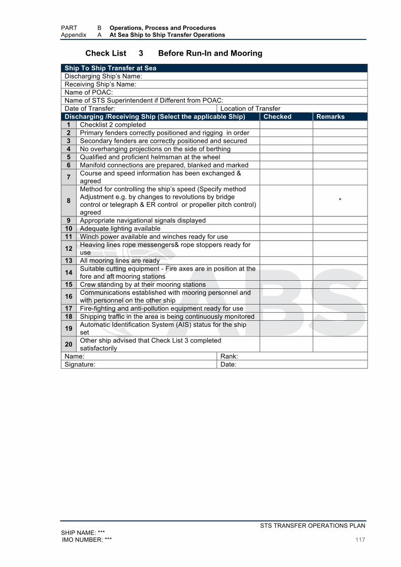
PART B Operations, Process and Procedures Appendix A At Sea Ship to Ship Transfer Operations
STS TRANSFER OPERATIONS PLAN SHIP NAME: *** IMO NUMBER: *** 117
Check List 3 Before Run-In and Mooring
Ship To Ship Transfer at Sea Discharging Ship’s Name: Receiving Ship’s Name: Name of POAC: Name of STS Superintendent if Different from POAC: Date of Transfer: Location of Transfer Discharging /Receiving Ship (Select the applicable Ship) Checked Remarks 1 Checklist 2 completed 2 Primary fenders correctly positioned and rigging in order 3 Secondary fenders are correctly positioned and secured 4 No overhanging projections on the side of berthing 5 Qualified and proficient helmsman at the wheel 6 Manifold connections are prepared, blanked and marked
7 Course and speed information has been exchanged & agreed
8
Method for controlling the ship’s speed (Specify method Adjustment e.g. by changes to revolutions by bridge control or telegraph & ER control or propeller pitch control) agreed
*
9 Appropriate navigational signals displayed 10 Adequate lighting available 11 Winch power available and winches ready for use
12 Heaving lines rope messengers& rope stoppers ready for use
13 All mooring lines are ready
14 Suitable cutting equipment - Fire axes are in position at the fore and aft mooring stations
15 Crew standing by at their mooring stations
16 Communications established with mooring personnel and with personnel on the other ship
17 Fire-fighting and anti-pollution equipment ready for use 18 Shipping traffic in the area is being continuously monitored
19 Automatic Identification System (AIS) status for the ship set
20 Other ship advised that Check List 3 completed satisfactorily
Name: Rank: Signature: Date:
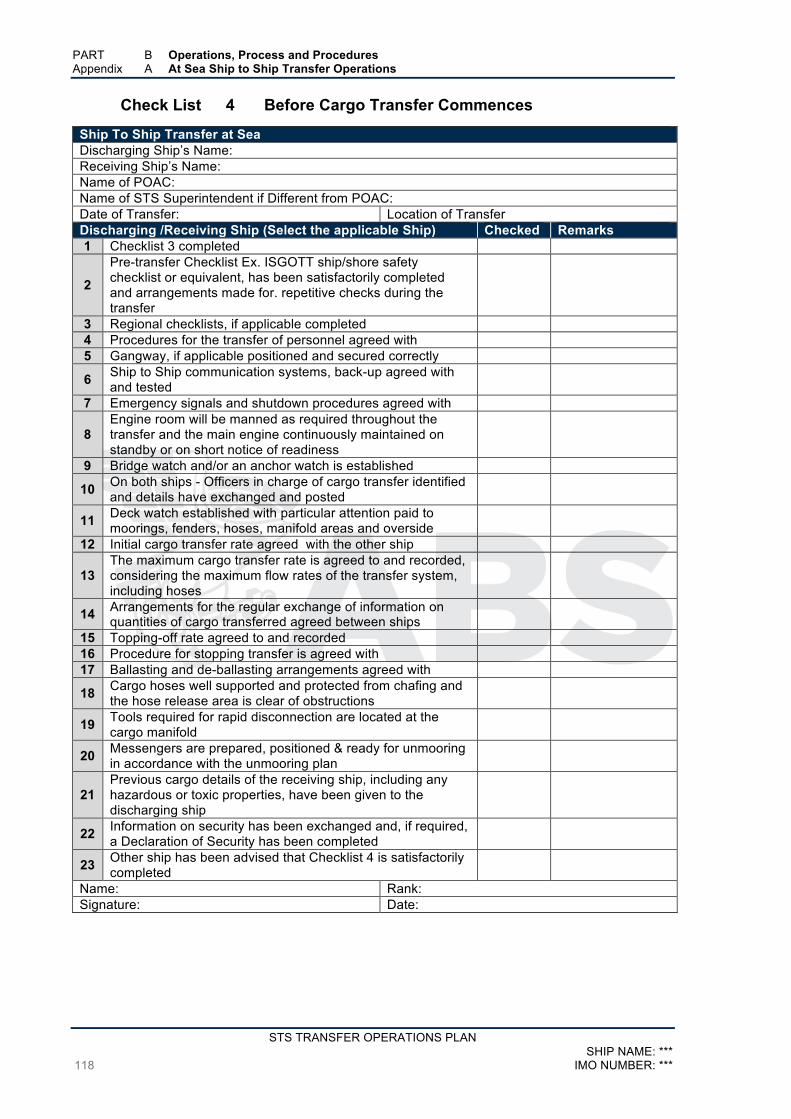
PART B Operations, Process and Procedures Appendix A At Sea Ship to Ship Transfer Operations
STS TRANSFER OPERATIONS PLAN SHIP NAME: ***
118 IMO NUMBER: ***
Check List 4 Before Cargo Transfer Commences
Ship To Ship Transfer at Sea Discharging Ship’s Name: Receiving Ship’s Name: Name of POAC: Name of STS Superintendent if Different from POAC: Date of Transfer: Location of Transfer Discharging /Receiving Ship (Select the applicable Ship) Checked Remarks 1 Checklist 3 completed
2
Pre-transfer Checklist Ex. ISGOTT ship/shore safety checklist or equivalent, has been satisfactorily completed and arrangements made for. repetitive checks during the transfer
3 Regional checklists, if applicable completed 4 Procedures for the transfer of personnel agreed with 5 Gangway, if applicable positioned and secured correctly
6 Ship to Ship communication systems, back-up agreed with and tested
7 Emergency signals and shutdown procedures agreed with
8 Engine room will be manned as required throughout the transfer and the main engine continuously maintained on standby or on short notice of readiness
9 Bridge watch and/or an anchor watch is established
10 On both ships - Officers in charge of cargo transfer identified and details have exchanged and posted
11 Deck watch established with particular attention paid to moorings, fenders, hoses, manifold areas and overside
12 Initial cargo transfer rate agreed with the other ship
13 The maximum cargo transfer rate is agreed to and recorded, considering the maximum flow rates of the transfer system, including hoses
14 Arrangements for the regular exchange of information on quantities of cargo transferred agreed between ships
15 Topping-off rate agreed to and recorded 16 Procedure for stopping transfer is agreed with 17 Ballasting and de-ballasting arrangements agreed with
18 Cargo hoses well supported and protected from chafing and the hose release area is clear of obstructions
19 Tools required for rapid disconnection are located at the cargo manifold
20 Messengers are prepared, positioned & ready for unmooring in accordance with the unmooring plan
21 Previous cargo details of the receiving ship, including any hazardous or toxic properties, have been given to the discharging ship
22 Information on security has been exchanged and, if required, a Declaration of Security has been completed
23 Other ship has been advised that Checklist 4 is satisfactorily completed
Name: Rank: Signature: Date:
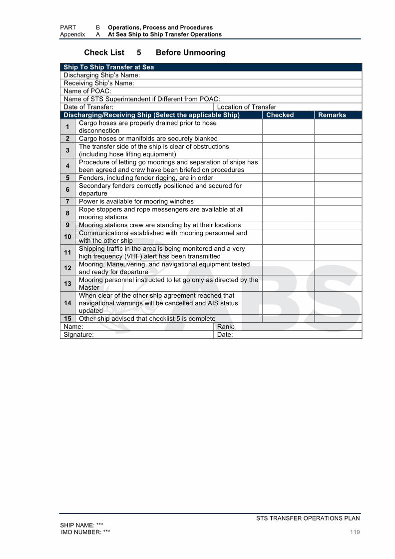
PART B Operations, Process and Procedures Appendix A At Sea Ship to Ship Transfer Operations
STS TRANSFER OPERATIONS PLAN SHIP NAME: *** IMO NUMBER: *** 119
Check List 5 Before Unmooring
Ship To Ship Transfer at Sea Discharging Ship’s Name: Receiving Ship’s Name: Name of POAC: Name of STS Superintendent if Different from POAC: Date of Transfer: Location of Transfer Discharging/Receiving Ship (Select the applicable Ship) Checked Remarks
1 Cargo hoses are properly drained prior to hose disconnection
2 Cargo hoses or manifolds are securely blanked
3 The transfer side of the ship is clear of obstructions (including hose lifting equipment)
4 Procedure of letting go moorings and separation of ships has been agreed and crew have been briefed on procedures
5 Fenders, including fender rigging, are in order
6 Secondary fenders correctly positioned and secured for departure
7 Power is available for mooring winches
8 Rope stoppers and rope messengers are available at all mooring stations
9 Mooring stations crew are standing by at their locations
10 Communications established with mooring personnel and with the other ship
11 Shipping traffic in the area is being monitored and a very high frequency (VHF) alert has been transmitted
12 Mooring, Maneuvering, and navigational equipment tested and ready for departure
13 Mooring personnel instructed to let go only as directed by the Master
14 When clear of the other ship agreement reached that navigational warnings will be cancelled and AIS status updated
15 Other ship advised that checklist 5 is complete Name: Rank: Signature: Date:

STS TRANSFER OPERATIONS PLAN SHIP NAME: ***
120 IMO NUMBER: ***
Appendix B At Port Ship to Ship Transfer Operations
Check List 6 Pre-Transfer In Port STS Cargo Transfer Check List
Check List 6A ISGOTT Ship/Shore Safety Check List
Check List 7 Pre- STS Cargo Transfer Checks in Port
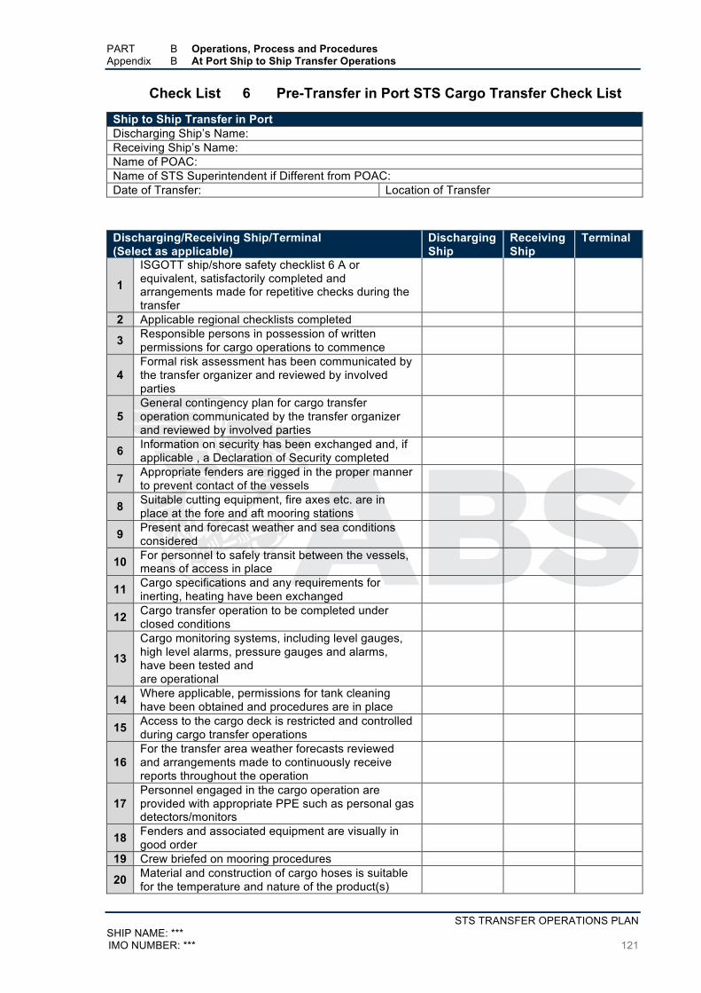
PART B Operations, Process and Procedures Appendix B At Port Ship to Ship Transfer Operations
STS TRANSFER OPERATIONS PLAN SHIP NAME: *** IMO NUMBER: *** 121
Check List 6 Pre-Transfer in Port STS Cargo Transfer Check List
Ship to Ship Transfer in Port Discharging Ship’s Name: Receiving Ship’s Name: Name of POAC: Name of STS Superintendent if Different from POAC: Date of Transfer: Location of Transfer
Discharging/Receiving Ship/Terminal (Select as applicable)
Discharging Ship
Receiving Ship
Terminal
1
ISGOTT ship/shore safety checklist 6 A or equivalent, satisfactorily completed and arrangements made for repetitive checks during the transfer
2 Applicable regional checklists completed
3 Responsible persons in possession of written permissions for cargo operations to commence
4 Formal risk assessment has been communicated by the transfer organizer and reviewed by involved parties
5 General contingency plan for cargo transfer operation communicated by the transfer organizer and reviewed by involved parties
6 Information on security has been exchanged and, if applicable , a Declaration of Security completed
7 Appropriate fenders are rigged in the proper manner to prevent contact of the vessels
8 Suitable cutting equipment, fire axes etc. are in place at the fore and aft mooring stations
9 Present and forecast weather and sea conditions considered
10 For personnel to safely transit between the vessels, means of access in place
11 Cargo specifications and any requirements for inerting, heating have been exchanged
12 Cargo transfer operation to be completed under closed conditions
13
Cargo monitoring systems, including level gauges, high level alarms, pressure gauges and alarms, have been tested and are operational
14 Where applicable, permissions for tank cleaning have been obtained and procedures are in place
15 Access to the cargo deck is restricted and controlled during cargo transfer operations
16 For the transfer area weather forecasts reviewed and arrangements made to continuously receive reports throughout the operation
17 Personnel engaged in the cargo operation are provided with appropriate PPE such as personal gas detectors/monitors
18 Fenders and associated equipment are visually in good order
19 Crew briefed on mooring procedures
20 Material and construction of cargo hoses is suitable for the temperature and nature of the product(s)

PART B Operations, Process and Procedures Appendix B At Port Ship to Ship Transfer Operations
STS TRANSFER OPERATIONS PLAN SHIP NAME: ***
122 IMO NUMBER: ***
Discharging/Receiving Ship/Terminal (Select as applicable)
Discharging Ship
Receiving Ship
Terminal
21
If electrically continuous hoses are used, the hoses are connected to the vessel with the insulated flange before being passed to the other vessel for connections
22 Cargo hose string is of adequate length and adequately supported
23 Cargo lines lined up in accordance with the cargo operation plan
24 Oil spill response equipment is on station and ready for immediate deployment
Signature Name Officer in Charge Discharging Ship Officer in Charge Receiving Ship Terminal STS Superintendent
PART B Operations, Process and Procedures Appendix B At Port Ship to Ship Transfer Operations
STS TRANSFER OPERATIONS PLAN SHIP NAME: *** IMO NUMBER: *** 123
Check List 6A ISGOTT Ship/Shore Safety Check List Coding of Items:
The presence of the letters ‘A’, ‘P’ or ‘R’ in the column entitled ‘Code’ indicates the following:
A (‘Agreement’). This indicates an agreement or procedure that should be identified in the ‘Remarks’ column of the Check-List or communicated in some other mutually acceptable form.
P (‘Permission’). In the case of a negative answer to the statements coded ‘P’, operations should not be conducted without the written permission from the appropriate authority.
R (‘Re-check’). This indicates items to be re-checked at appropriate intervals, as agreed between both parties, at periods stated in the declaration.
The joint declaration should not be signed until both parties have checked and accepted their
assigned responsibilities and accountabilities.
Ship’s Name: Berth: Port: Date of Arrival: Time of Arrival:
Bulk Liquid Oil – General Physical Check Ship Terminal Code Remarks
1 There is safe access between the ship and shore. R
2 The ship is securely moored. R
3 The agreed ship/shore communication system is operative. A R
System: Backup System:
4 Emergency towing-off pennants are correctly rigged and positioned. R
5 The ship’s fire hoses and fire-fighting equipment are positioned and ready for immediate use. R
6 The terminal’s fire-fighting equipment is positioned and ready for immediate use. R
7 The ship’s cargo and bunker hoses, pipelines and manifolds are in good condition, properly rigged and appropriate for the service intended.
8 The terminal’s cargo and bunker hoses or arms are in good condition, properly rigged and appropriate for the service intended.
9 The cargo transfer system is sufficiently isolated and drained to allow safe removal of blank flanges prior to connection.
10 Scuppers and save-alls on board are effectively plugged and drip trays are in position and empty.
R
11 Temporarily removed scupper plugs will be constantly monitored. R
12 Shore spill containment and sumps are correctly managed. R
13 The ship’s unused cargo and bunker connections are properly secured with blank flanges fully bolted.
14 The terminal’s unused cargo and bunker connections are properly secured with blank flanges fully bolted.

PART B Operations, Process and Procedures Appendix B At Port Ship to Ship Transfer Operations
STS TRANSFER OPERATIONS PLAN SHIP NAME: ***
124 IMO NUMBER: ***
Bulk Liquid Oil – General Physical Check Ship Terminal Code Remarks
15 All cargo, ballast and bunker tank lids are closed.
16 Sea and overboard discharge valves, when not in use, are closed and visibly secured.
17 All external doors, ports and windows in the accommodation, stores and machinery spaces are closed. Engine room vents may be open.
R
18 The ship’s emergency fire control plans are located externally. Location
If the ship is fitted, or is required to be fitted, with an inert gas system (IGS), the following points
should be physically checked:
Inert Gas System Ship Terminal Code Remarks
19 Fixed IGS pressure and oxygen content recorders are working. R
20 All cargo tank atmospheres are at positive pressure with oxygen content of 8% or less by volume.
P R
Bulk Liquid Oil – General Verbal Verification Ship Terminal Code Remarks 21 The ship is ready to move under its own power. P R
22 There is an effective deck watch in attendance on board and adequate supervision of operations on the ship and in the terminal
R
23 There are sufficient personnel on board and ashore to deal with an emergency. R
24 The procedures for cargo, bunker and ballast handling have been agreed. A R
25 The emergency signal and shutdown procedure to be used by the ship and shore have been explained and understood.
A
26 Material Safety Data Sheets (MSDS) for the cargo transfer have been exchanged where requested.
P R
27 The hazards associated with toxic substances in the cargo being handled have been identified and understood.
A R
H2S Content: Benzene Content:
28 An International Shore Fire Connection has been provided.
29 The agreed tank venting system will be used. A R Method:
30 The requirements for closed operations have been agreed. R
31 The operation of the P/V system has been verified.
32 Where a vapor return line is connected, operating parameters have been agreed. A R
33 Independent high level alarms, if fitted, are operational and have been tested. A R
34 Adequate electrical insulating means are in place in the ship/shore connection. A R
35 Shore lines are fitted with a non-return valve, or procedures to avoid back filling have been discussed.
P R

PART B Operations, Process and Procedures Appendix B At Port Ship to Ship Transfer Operations
STS TRANSFER OPERATIONS PLAN SHIP NAME: *** IMO NUMBER: *** 125
Bulk Liquid Oil – General Verbal Verification Ship Terminal Code Remarks
36 Smoking rooms have been identified and smoking requirements are being observed. A R
Nominated smoking rooms:
37 Naked light regulations are being observed. A R
38 Ship/shore telephones, mobile phones and pager requirements are being observed. A R
39 Hand torches (flashlights) are of an approved type.
40 Fixed VHF/UHF transceivers and AIS equipment are on the correct power mode or switched off.
41 Portable VHF/UHF transceivers are of an approved type.
42 The ship’s main radio transmitter aerials are earthed and radars are switched off.
43 Electric cables to portable electrical equipment within the hazardous area are disconnected from power.
44 Window type air conditioning units are disconnected.
45
Positive pressure is being maintained inside the accommodation, and air conditioning intakes, which may permit the entry of cargo vapors, are closed.
46 Measures have been taken to ensure sufficient mechanical ventilation in the pump room. R
47 There is provision for an emergency escape.
48 The maximum wind and swell criteria for operations have been agreed. A
Stop cargo at: Disconnect at: Unberth at:
49 Security protocols have been agreed between the Ship Security Officer and the Port Facility Security Officer, if appropriate.
A
50
Where appropriate, procedures have been agreed for receiving nitrogen supplied from shore, either for inerting or purging ship’s tanks, or for line clearing into the ship.
A P
If the ship is fitted, or is required to be fitted, with an inert gas system (IGS) the following statements
should be addressed:
Inert Gas System Ship Terminal Code Remarks
51 The IGS is fully operational and in good working order. P
52 Deck seals, or equivalent, are in good working order. R
53 Liquid levels in pressure/vacuum breakers are correct.
R
54 The fixed and portable oxygen analyzers have been calibrated and are working properly.
R
55 All the individual tank IG valves (if fitted) are correctly set and locked.
R
PART B Operations, Process and Procedures Appendix B At Port Ship to Ship Transfer Operations
STS TRANSFER OPERATIONS PLAN SHIP NAME: ***
126 IMO NUMBER: ***
56
All personnel in charge of cargo operations are aware that, in the case of failure of the inert gas plant, discharge operations should cease and the terminal be advised.
If the ship is fitted with a Crude Oil Washing (COW) system, and intends to crude oil wash, the
following statements should be addressed:
Crude Oil Washing Ship Terminal Code Remarks
57 The Pre-Arrival COW check-list, as contained in the approved COW manual, has been satisfactorily completed.
58 The COW check-lists for use before, during and after COW, as contained in the approved COW manual, are available and being used.
R

PART B Operations, Process and Procedures Appendix B At Port Ship to Ship Transfer Operations
STS TRANSFER OPERATIONS PLAN SHIP NAME: *** IMO NUMBER: *** 127
Check List 7 Pre- STS Cargo Transfer Checks in Port
Ship to Ship Transfer in Port Discharging Ship’s Name: Receiving Ship’s Name: Name of POAC: Name of STS Superintendent if Different from POAC: Date of Transfer: Location of Transfer
Discharging /Receiving Ship/Terminal (Select as applicable ) Time
of Check
Time of
Check
Time of
Check
1 Prevailing conditions of the weather and the sea conditions are within the agreed boundaries.
2 Appropriate PPE have been worn by personnel engaged in cargo transfer operations.
3 Cargo systems, Hose strings, manifold connections confirmed to be free of leakage.
4 Due considerations having been given to the expected change of freeboards, cargo hoses properly supported.
5 All cargo instrumentation such as monitoring systems, level alarms, gauges for level and pressure are functioning appropriately.
6 Transfer of cargo under closed conditions confirmed
7 Surrounding the STS vessels sea surface checked to be free of pollution.
8 Confirmation of no built up toxic and/or hazardous gases in spaces prone to such possibilities.
9 Mooring lines correctly tensioned at various phases of the transfer.
10 Emergency towing-off pennants adjusted appropriately.
11 Cargo tanks secured after transferring cargo from or to the tanks
12 Cargo and ballast tank levels checked and confirmed appropriate based on their status
Checked By:
Date Checked:

STS TRANSFER OPERATIONS PLAN SHIP NAME: ***
128 IMO NUMBER: ***
Appendix C Personnel Transfers by Crane Checklist
Check List 8 Personnel Transfers by Crane

PART B Operations, Process and Procedures Appendix C Personnel Transfers by Crane Checklist (Example)
STS TRANSFER OPERATIONS PLAN SHIP NAME: *** IMO NUMBER: *** 129
Check List 8 Personnel Transfers by Crane Ship to Ship Ship’s Name: Date of Transfer: Location of Transfer Ship’s Crane certified for personnel lifting in accordance with the requirements of the ABS Guide for Certification of Lifting Appliances
A) Crane prior to the Ship’s Arrival at the STS Location
1
A qualified person has completed a visual inspection of all operating parts, including runner wire, sheaves, cargo block hooks, hydraulic piping, etc. Confirmed that:
i) Checked wires are lubricated with no signs of kinks, rust or nips.
ii) Checked Wires are evenly stowed on the winch drum with no
tangles or loops.
iii) Checked hook swivel.
iv) Checked wire rope terminations at hook and winch drum are in
place and secure.
v) Manufacturer’s inspection recommendations completed
2
Confirmed that: The manufacturer’s functional operating checks and control tests in accordance with the manufacturer’s instruction manual have been completed satisfactorily. Miscellaneous manufacturer’s recommendations have been taken in to considerations
3 Confirmed that the environmental conditions such as wind speed and vessel movements are suitable to perform the operation.
4
Confirmed that the following were checked and tested successfully: i) Crane safety devices,
ii) Operation of limit switches, hoisting upper and lower limits,
luffing upper and lower limits
iii) Hook safety latch,
iv) brakes, etc
5 Confirmed that: Emergency mode of operation tested. Including alternative means of lowering in case the crane loses primary power i.e. emergency source of power or manual operation, such as by the use of hand pumps.
6 Date of last wire test Date of last load test

PART B Operations, Process and Procedures Appendix C Personnel Transfers by Crane Checklist (Example)
STS TRANSFER OPERATIONS PLAN SHIP NAME: ***
130 IMO NUMBER: ***
B) Personnel Transfer Basket (PTB) Prior to the Ship’s Arrival at the STS Location 1 Confirmation that the Personnel Transfer Basket has a valid certificate
2
Confirmation that in accordance with manufacturer’s guidance a complete visual check has been performed of all components of the PTB, these include the lifting ring, load line, safety load line, lifting sling and shock cords, aluminum rings, ultraline rigging line, splices, etc.
3 Confirmation that deterioration, cracks, distortion, weld integrity, rust etc. are not visible on the steel components.
4 In accordance with the manufacturer’s guidelines tag lines are attached to the bottom outside of the basket
5
The condition of personal flotation devices (PFD) has been checked and there are sufficient to ensure their availability for all personnel being transported. The PFD should be suitable for basket transfer, with due consideration being given to the height above sea level)
C) Prior to Personnel Transfer Operation
1 To ensure that transfer procedures have been well understood all participants have been properly briefed
2 Crane operator is experienced and fully familiar with the international crane hand signals.
3 In accordance with the owner’s instructions and manufacturer’s guidance, the officer in charge officer in charge confirms that the personnel basket and crane have been inspected and tested before use.
4 Adequate personnel are available to perform the transfer safely
5
Confirmation that a pre-transfer safety meeting has been completed and the transfer plan has been agreed with. Discussions have included methods of communications, use of standard crane signals, etc.
6
Prevailing conditions, including sea state, currents, wind speed and direction and weather, have been assessed to ensure that the transfer can be conducted safely Where required confirmed adequate availability of search lights and flood lights.
7 No obstructions on deck to safely land the basket 8 Simulated transfer completed prior to first transfer of personnel
9 Contact has been established between the two vessels on the radio and the responsible person in charge of the transfer arrangements on deck
10 As far as possible raising and lowering of the basket will be generally carried out above the sea and not above the vessel
11 The lifting equipment’s reach extends sufficiently to ensure that the basket will not be pulled over excessively during transfer
12 At the transfer location a lifebuoy with light and line is readily available

PART B Operations, Process and Procedures Appendix C Personnel Transfers by Crane Checklist (Example)
STS TRANSFER OPERATIONS PLAN SHIP NAME: *** IMO NUMBER: *** 131
D) During Personnel Transfer Operation
1 The transfer procedure and transfer sequence for personnel have been understood and personnel have been instructed to hold on at all times and observing instructions from those in charge of the operation
2 Agreement received from the personnel being transferred
3
At a minimum Personnel Protective Equipment – Personnel Flotation Device and Helmet have been worn. PFDs should be equipped with suitable means of illumination during night time transfers.
4 Both vessels have the authority to stop the transfer if conditions are considered unsafe.
5 A rescue boat is available for immediate launching in the event that a person falls into the sea during the transfer.
6 Limitations associated with the minimum or maximum angles of crane booms considered. The minimum outboard reach is more than five meters at the lowest jib angle.
Name: Rank: Signature:
Date:

STS TRANSFER OPERATIONS PLAN SHIP NAME: ***
132 IMO NUMBER: ***
Appendix D STS Transfers Involving Vapor Balancing
Check List 9 STS Transfers Involving Vapor Balancing

PART B Operations, Process and Procedures Appendix D STS Transfers Involving Vapor Balancing
STS TRANSFER OPERATIONS PLAN SHIP NAME: *** IMO NUMBER: *** 133
Check List 9 STS Transfers Involving Vapor Balancing
Ship to Ship Transfer in Port Checklist for STS Transfers Involving Vapor Balancing Discharging Ship’s Name: Receiving Ship’s Name: Name of POAC: Name of STS Superintendent if Different from POAC: Date of Transfer: Location of Transfer Discharging/Receiving Ship/Terminal (Select as applicable )
Discharging Ship
Receiving Ship Remarks
1 Pressure in cargo tanks (mm, WG or psi) 2 Oxygen content in tank below 8% by volume
3 Responsible persons in possession of written permissions for cargo operations to commence
4 Within the last 24-hours tanks high level and overfill alarms tested.
5 Vapor recovery/balancing valves are correctly positioned
6 Vapor recovery hose inerted
7 Deck seal and PV breaker levels have been checked and are satisfactory
8 Leak testing performed by (State method)
9
Pressure and vacuum relief settings: Liquid PV Breaker Tank PV Valves Mast head PV Valve(s) Other PV relieving devices
(Specify)
10 Type of vapors from present/previous cargoes (Refer to MSDS)
11 Initial cargo transfer rate (m3/hr or bbls/hr) 12 Maximum cargo transfer rate (m3/hr or bbls/hr)
13 Maximum acceptable pressure differential at maximum transfer rate (mm, WG or psi)
14 Cargo tank pressure range to be maintained (mm, WG or psi)
15 Cargo tank pressure alarm set points: High alarm (mm,WG or psi) Low alarm (mm, WG or psi)
16 Inert gas main pressure alarm set points: High alarm (mm, WG or psi) Low alarm (mm, WG or psi)
17
Vapor emission control system pressure alarm set points: High alarm (mm,WC or psi) Low alarm (mm, WG or psi)
18 Oxygen analyzer checked and calibrated Alarm set point (% volume)
(Specify)
19 Agreement of procedures – Start up, shutdown, Low Pressure & High Pressure alarms
Name: Rank: Signature: Date:

STS TRANSFER OPERATIONS PLAN SHIP NAME: ***
134 IMO NUMBER: ***
Appendix E STS Transfers Reverse Lightering Consideration
1 Reverse Lightering Operations Considerations 1.1 General Concept
Reverse lightering or topping-off, is an STS transfer operation in which a fully laden
tanker, is maneuvered alongside a partially laden very large crude carrier (VLCC) or
ultra large crude carrier (ULCC) in order to transfer cargo to the larger vessel.
This differentiates the operation from conventional STS activities in which the
maneuvering vessel is typically.in a ballast condition receives cargo from the larger
vessel.
1.2 Fendering Considerations
The maneuvering vessel in reverse lightering operations, is often fully laden and will
therefore be more difficult to maneuver alongside in conditions which are not calm
weather conditions.
The maneuvering ship is normally rigged with primary fenders.
Selection of fenders are to take into account the potential increase in berthing
velocities and higher angles of approach when compared to conventional berthing for
lightering operations.
To limit berthing velocities additional environmental limits may be imposed on the
operation or the requirement for the use of tugs to assist in berthing.
i) Prior to reaching an agreement to a reverse lightering operation, the
parties involved should carry out a risk assessment as outlined in
Section .6.2 of this Plan.
ii) Estimated berthing energy should be calculated using the formulae in
appendix H of the CDI/ICS/OCIMF/SIGTTO “Ship-to-Ship Transfer
Guide for Petroleum, Chemicals and Liquefied Gases’, 2013 (STS
Guide)
iii) To assist in the identification of weather windows for an operation,
consideration may be given to using STS berthing simulation tools to
calculate berthing forces and stand-off distances in varying
environmental conditions.
iv) Weather, sea and swell conditions will influence the ability of the
loaded vessel to maneuver during the berthing approach, and
therefore is to be considered as a limiting factor.
Consideration is to be given to the effect of approach velocities on the
berthing energy absorption characteristics of the fender system.

STS TRANSFER OPERATIONS PLAN SHIP NAME: *** IMO NUMBER: *** 135
v) Consideration is to be given to the availability of fenders of a required
type and size and of equipment, such as service vessels, capable of
safely handling the fenders.
STS TRANSFER OPERATIONS PLAN SHIP NAME: ***
136 IMO NUMBER: ***
Appendix F STS Transfers Assembly of Hose Lengths
1 Guidance on the Assembly of Hose Lengths 1.1 General Concept
Hoses may be delivered in individual lengths to either one of the STS vessels. In such
situations it will be necessary for the ship’s personnel to connect the individual hose
lengths together in order to assemble one or more hose lengths with sufficiently long
enough length to be deployed between the vessels performing the STS transfer
operation.
1.2 Lengths of Hose not Within the Containment Area
Where sections of hose lengths with connection flanges are deployed outside the
containment areas of both vessels, it must be ensured that they have been connected
in a manner that will ensure their liquid containment integrity for the entire duration
of the cargo transfer operation.
1.3 Miscellaneous requirements for Hose Connections
To enable ship’s personnel to connect hose lengths effectively, the following are
necessary at a minimum:
i) Appropriate new gaskets
ii) Reliable nuts and bolts
iii) Appropriately sized torque wrenches
iv) The gasket manufacturer’s instructions regarding the optimum final
torque compression setting for the supplied gaskets.
v) Metal scrapers, aerosol gasket removers, wire brushes.
1.4 Preparatory measures for Hose Connections
i) To ensure that all residues and debris from previous gaskets or other
material are removed completely, prior to connection of the two hoses, the
flange faces should be inspected in detail and cleaned.
ii) The use of metal flanged scrapers, an aerosol gasket removers and wire
brushes may assist in ensuring a good and flat flange surface.
iii) The threads of the bolts and nuts are to be lubricated
iv) New ANSI ring gaskets would center themselves with the bolts in place.
v) Under no circumstance should old gaskets be used.
1.5 Tightening of Flanges for Hose Connections
Once the flange has been assembled and all nuts have been secured to the bolts by
hand with the joint in place, it is imperative that a sequence is to be followed while
using the wrench. This is achieved by temporary marking the flange with numbers.

PART B Operations, Process and Procedures Appendix F STS Transfers Assembly of Hose Lengths
STS TRANSFER OPERATIONS PLAN SHIP NAME: *** IMO NUMBER: *** 137
A uniform gap around the circumference is to be maintained between the flanges
during the process of tightening.
Figure 11 Flange tightening procedure
1st Round During the first round, nuts are to be hand wrench tightened.
2nd Round A hand wrench should again be used for the second round of
tightening.
3rd Round A Torque wrench is to be used to tighten the nuts up to 25% full
torque
4rd Round A Torque wrench is to be used to tighten the nuts up to 50% full
torque
5rd Round A Torque wrench is to be used to tighten the nuts up to 75% full
torque
6rd Round A Torque wrench is to be used to tighten the nuts up to 100% full
torque

PART B Operations, Process and Procedures Appendix F STS Stransfers Assembly of Hose Lengths
STS TRANSFER OPERATIONS PLAN SHIP NAME: ***
138 IMO NUMBER: ***
Check A Torque wrench is to be used to verify that the nuts do not move at
100% full torque
Check The torque on the nuts should be checked continuously, specifically
after 24 hours since most of the short term pre-load loss occurs
within 24 hours after initial tightening.

STS TRANSFER OPERATIONS PLAN SHIP NAME: *** IMO NUMBER: *** 139
Appendix G STS Transfers Guidance on Risk Assessments
G1 High Level Risk Examples
G2 Casual Factors Leading to High Level Risks Examples
G3 Risk Mitigation Measures Examples

PART B Operations, Process and Procedures Appendix G STS Transfers Guidance on Risk Assessments
STS TRANSFER OPERATIONS PLAN SHIP NAME: ***
140 IMO NUMBER: ***
G1 High Level Risk Examples
Table 8
High Level Risk Description of Risk
Low Energy Collision During the phases of berthing/un-berthing and side-by-side Operation, inadequate control may lead to hull to hull contact/collision leading to physical damage to one or both ships
Mooring Operations During mooring, unmooring and side-by-side operations, inadequate control leads to personal injury or fatality
High Energy Collision
When ships are involved in STS transfer operations or if a third party vessel is passing, inadequate control may cause a high energy collision during mooring, unmooring or transfer operations resulting in significant equipment damage, fatalities and loss of containment
Loss of Containment
Inadequate control during transfer may lead to Hardware failure, overflow or overpressure and/or a possible loss of containment and cargo release
Loss of Containment Vapor
A loss of containment and vapor release leading to ignition back to source resulting in fatalities/injury/hardware/steelwork damage may be the result of inadequate control
Loss of Containment Vapor in Confined Space
The possibility of that of a loss of containment leading to vapor collection in a confined space, leading to ignition with explosion, causing fatalities/injury and hull damage may be the result of inadequate control.
Personnel Transfer
The failure or the improper use of equipment used in personnel transfer may leads to a loss of control during transfer resulting in fatality or injury
Damage to Cargo Tanks Damage to cargo tank structure resulting in the ship being unfit to trade may be caused due to cargo sloshing caused due to ship motions in a condition of prevailing swell conditions.
Personnel Injury During Hose handling
Injury or fatality and damage to assets may be caused due to equipment failure or failure to follow proper procedures.
Mooring Breakaway
A loss of containment, damage to cargo equipment, mooring failures and risk of personal injury may be caused due to failure to maintain mooring integrity, deteriorating weather and/or poor maneuvering procedures.

PART B Operations, Process and Procedures Appendix G STS Transfers Guidance on Risk Assessments
STS TRANSFER OPERATIONS PLAN SHIP NAME: *** IMO NUMBER: *** 141
G2 Casual Factors Leading to High Level Risks
Table 9
Factors Description
Steering/propulsion failure Damaged moorings due to chafing and cyclic loading
Fender defects Inadequate compatibility study – personnel landing area
Inadequate fendering Defective personnel transfer equipment
Mismatched maneuvering characteristics Inadequate transfer equipment (type of approval/not fit for purpose).
Pilotage error Level measurement and overfill protection systems inadequate for open water operation
Insufficient maneuvering room Level measurement and overfill protection systems inadequate for open water operation
Inadequate watch keeping Transfer rate too high Inadequate communication Defective overfill protection Inadequate training Inadequate contingency planning Inadequate procedures Inadequate incident management Inadequate experience Large roll angles Fatigue Different roll periods Failure to follow procedures Tug/support vessel failure Abnormal metocean conditions Passing ship effect
Poor visibility Inadequate compatibility study bridge wing separation and parallel body lengths
Inadequate site selection Inadequate equipment inspection, testing and maintenance
Inadequate weather forecasting Equipment not fit for purpose Inadequate tug/support vessel Equipment unapproved/not fit for purpose Inadequate operational planning and control Mooring equipment failure
Inadequate planning for emergency breakaway Inadequate information on vessel motion limits for all filling levels
PART B Operations, Process and Procedures Appendix G STS Transfers Guidance on Risk Assessments
STS TRANSFER OPERATIONS PLAN SHIP NAME: ***
142 IMO NUMBER: ***
G3 Risk Mitigation Measures Examples
Table 10
Item Risk Mitigation measure STS Superintendent – Ship handling skills and local knowledge
Experienced STS Superintendent available on maneuvering ship and responsible for operation, liason and assisting with mooring unmooring maneuvers
Knowledge of ship handling characteristics Ship handling characteristics reflected in maneuvering plan
Bridge team experience and competency
High standard of bridge team management established through experience and specific STS training
Operating procedures
• Clear and detailed operating procedures established for all phases of the STS operation, including ramp up/down procedures and maximum loading rates.
• Procedures define communication requirements, responsible parties and accountabilities for each phase of the operation.
• For open water STS transfer the operating procedures will address visibility, the monitoring of third party traffic and detail the actions to be taken if third party traffic is predicted to enter closest point of approach (CPA) limits.
• Crews are trained and familiar with operating procedures
Contingency planning
• Detailed contingency plans are established for STS specific emergencies.
• Plans address control, responsibility and actions required on both ships.
• Crews trained and drilled in emergency procedures
STS equipment fit for purpose
All equipment used in the STS is fit for purpose and meets appropriate international standards and conforms to accepted industry guidelines
Pre and post-operational checks
Detailed checklists, as per accepted industry guidance, completed checks for all phases of the transfer operation
Life cycle equipment replacement policy
Life cycle equipment replacement policy established on the basis of operational experience and manufacturer’s recommendations
Overfill alarms/filling valve shutdown
Overfill and tank protection alarms and shutdown systems are fully operational at all times and maximum fill levels are adjusted to ensure that these systems operate effectively in open water where appropriate.
Personnel resource and capability
Adequate competent and experienced personnel are available on both ships to ensure effective operational control and acceptable hours of work
STS environmental operating limits
Clear operating limits defined in the operating procedure for all stages of the operation. The operating limits are to consider:
• Restrictions due to poor visibility/night time operations
• Maneuvering capability
• Operating limits of mooring and fendering systems
• Where applicable, motion studies to define maximum
environmental conditions for an acceptable sloshing risk when
cargo transfer operations are undertaken in open water
STS TRANSFER OPERATIONS PLAN SHIP NAME: *** IMO NUMBER: *** 143
Appendix H Fender Selection Assistance Request Form

STS TRANSFER OPERATIONS PLAN SHIP NAME: ***
144 IMO NUMBER: ***
Fender Selection Assistance Request Form for ship to ship use
To be filled out prior to contacting fender providers Location of Site: Potential sea state:
Potential Beaufort Scale:
Ship A Ship B Type of Ship Displacement Tonnage (at start of STS operations)
Length overall Length between perpendiculars Parallel body length at start of STS operation (Forward & Aft of centerline)
F--------A-------- F--------A--------
Parallel body length at completion of operation (Forward & Aft of centerline)
F--------A-------- F--------A--------
Beam Freeboard at start of operation Freeboard at completion of operation Relative approach velocity of ships
Other relevant information:

STS TRANSFER OPERATIONS PLAN SHIP NAME: *** IMO NUMBER: *** 145
Appendix I Ship Specific Plans
1.0 General Arrangement
1.1 Tank Capacity Plan
1.2 Manifold and Drip Tray Arrangement and Details
1.3 Anchor Handling and Mooring Arrangement
1.4 List of Personnel, Location Responsibilities, Emergencies
1.5 Ship Interest Contacts

PART B Operations, Process and Procedures Appendix I Ship Specific Plans
STS TRANSFER OPERATIONS PLAN SHIP NAME: ***
146 IMO NUMBER: ***
1.0 General Arrangement (To be replaced by ship specific General Arrangement Plan)
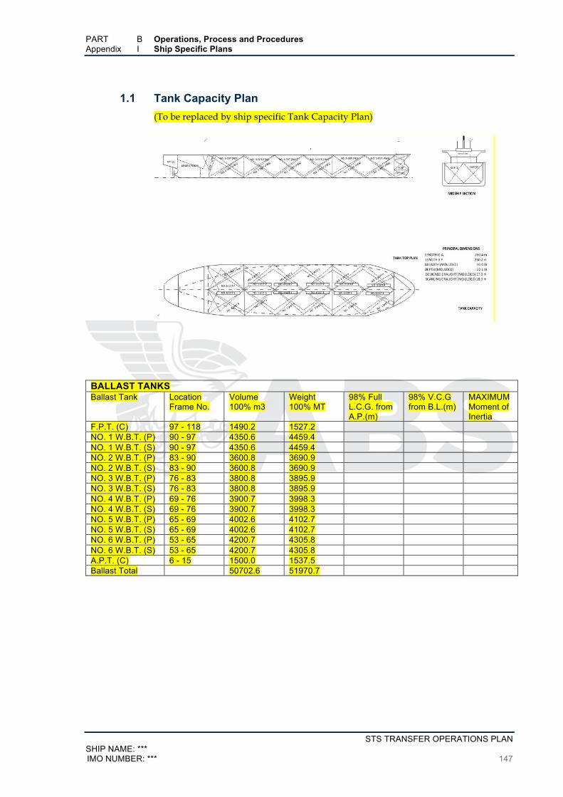
PART B Operations, Process and Procedures Appendix I Ship Specific Plans
STS TRANSFER OPERATIONS PLAN SHIP NAME: *** IMO NUMBER: *** 147
1.1 Tank Capacity Plan (To be replaced by ship specific Tank Capacity Plan)
BALLAST TANKS Ballast Tank Location
Frame No. Volume 100% m3
Weight 100% MT
98% Full L.C.G. from A.P.(m)
98% V.C.G from B.L.(m)
MAXIMUM Moment of Inertia
F.P.T. (C) 97 - 118 1490.2 1527.2 NO. 1 W.B.T. (P) 90 - 97 4350.6 4459.4 NO. 1 W.B.T. (S) 90 - 97 4350.6 4459.4 NO. 2 W.B.T. (P) 83 - 90 3600.8 3690.9 NO. 2 W.B.T. (S) 83 - 90 3600.8 3690.9 NO. 3 W.B.T. (P) 76 - 83 3800.8 3895.9 NO. 3 W.B.T. (S) 76 - 83 3800.8 3895.9 NO. 4 W.B.T. (P) 69 - 76 3900.7 3998.3 NO. 4 W.B.T. (S) 69 - 76 3900.7 3998.3 NO. 5 W.B.T. (P) 65 - 69 4002.6 4102.7 NO. 5 W.B.T. (S) 65 - 69 4002.6 4102.7 NO. 6 W.B.T. (P) 53 - 65 4200.7 4305.8 NO. 6 W.B.T. (S) 53 - 65 4200.7 4305.8 A.P.T. (C) 6 - 15 1500.0 1537.5 Ballast Total 50702.6 51970.7

PART B Operations, Process and Procedures Appendix I Ship Specific Plans
STS TRANSFER OPERATIONS PLAN SHIP NAME: ***
148 IMO NUMBER: ***
CARGO OIL TANKS Cargo Oil Tank Location
Frame No. Volume 100% m3
Weight 100% MT
98% Full L.C.G. from A.P.(m)
98% V.C.G from B.L.(m)
MAXIMUM Moment of Inertia
NO. 1 W.B.T. (P)
90 - 97 11600.7 11367.66
NO. 1 W.B.T. (S)
90 - 97 11600.7 11367.66
NO. 2 W.B.T. (P)
83 - 90 15000.6 14699.27
NO. 2 W.B.T. (S)
83 - 90 15000.6 14699.27
NO. 3 W.B.T. (P)
76 - 83 14500.8 14209.51
NO. 3 W.B.T. (S)
76 - 83 14500.8 14209.51
NO. 4 W.B.T. (P)
69 - 76 14490.6 14199.51
NO. 4 W.B.T. (S)
69 - 76 14490.6 14199.51
NO. 5 W.B.T. (P)
65 - 69 14495.4 14204.21
NO. 5 W.B.T. (S)
65 - 69 14495.4 14204.21
NO. 6 W.B.T. (P)
53 - 65 14103.6 13820.28
NO. 6 W.B.T. (S)
53 - 65 14103.6 13820.28
SLOP T (P) 51 - 53 2359.4 2312.004 SLOP T (S) 51 - 53 2359.4 2312.004 Cargo Oil Total 173102.2 169624.9
FRESH WATER TANKS Fresh Water Tank
Location Frame No.
Volume 100% m3
Weight 100% MT
98% Full L.C.G. from A.P.(m)
98% V.C.G from B.L.(m)
MAXIMUM Moment of Inertia
F.W..T. (P) 1 - 12 320.5 320.5 F.W..T. (S) 1 - 12 320.5 320.5 Fresh Water Total
641 641
HEAVY FUEL OIL TANKS Heavy Fuel Oil Tank
Location Frame No.
Volume 100% m3 / 98% m3
Weight 100% MT
98% Full L.C.G. from A.P.(m)
98% V.C.G from B.L.(m)
MAXIMUM Moment of Inertia
H.F.O. STOR.T. (P)
16 - 53 1900.0/1862.0 1862.745
H.F.O. STOR.T. (S)
16 - 53 1890.0/1852.2 1852.941
H.F.O. SERV.T. (P)
38 -42 98.0/96.04 96.07843
H.F.O. SETT.T. (P)
42 - 48 129.0/126.4 126.4706
L.S.H.F.O. SETT.T. (P)
48 - 53 109.4/107.2 107.2549
Heavy Fuel Oil Total
4126.4/4043.9 4045.49
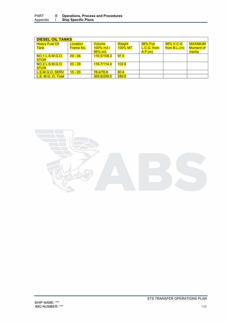
PART B Operations, Process and Procedures Appendix I Ship Specific Plans
STS TRANSFER OPERATIONS PLAN SHIP NAME: *** IMO NUMBER: *** 149
DIESEL OIL TANKS Heavy Fuel Oil Tank
Location Frame No.
Volume 100% m3 / 98% m3
Weight 100% MT
98% Full L.C.G. from A.P.(m)
98% V.C.G from B.L.(m)
MAXIMUM Moment of Inertia
NO.1 L.S.M.G.O. STOR
29 - 34 110.5/108.3 97.5
NO.2 L.S.M.G.O. STOR
20 - 29 116.7/114.4 102.9
L.S.M.G.O. SERV 15 - 20 78.4/76.8 80.4 L.S. M.G. O. Total 305.6/299.5 280.8
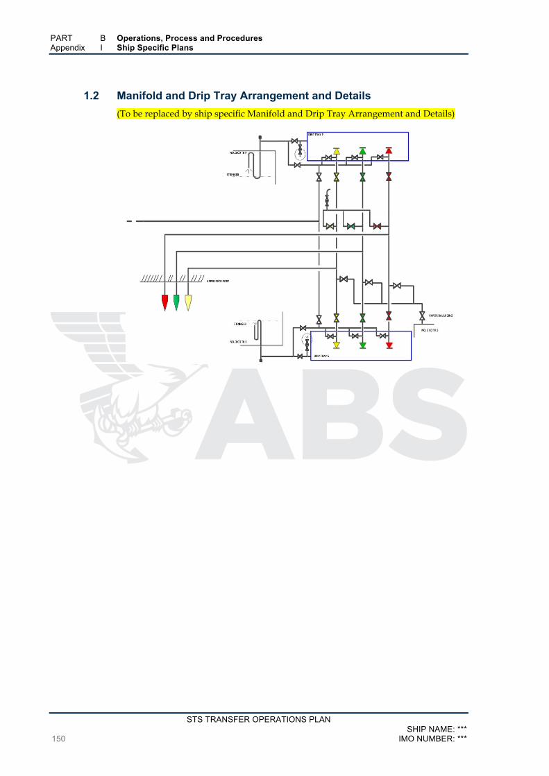
PART B Operations, Process and Procedures Appendix I Ship Specific Plans
STS TRANSFER OPERATIONS PLAN SHIP NAME: ***
150 IMO NUMBER: ***
1.2 Manifold and Drip Tray Arrangement and Details (To be replaced by ship specific Manifold and Drip Tray Arrangement and Details)
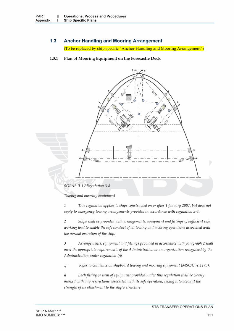
PART B Operations, Process and Procedures Appendix I Ship Specific Plans
STS TRANSFER OPERATIONS PLAN SHIP NAME: *** IMO NUMBER: *** 151
1.3 Anchor Handling and Mooring Arrangement (To be replaced by ship specific “Anchor Handling and Mooring Arrangement”)
1.3.1 Plan of Mooring Equipment on the Forecastle Deck
SOLAS II-1 / Regulation 3-8
Towing and mooring equipment
1 This regulation applies to ships constructed on or after 1 January 2007, but does not
apply to emergency towing arrangements provided in accordance with regulation 3-4.
2 Ships shall be provided with arrangements, equipment and fittings of sufficient safe
working load to enable the safe conduct of all towing and mooring operations associated with
the normal operation of the ship.
3 Arrangements, equipment and fittings provided in accordance with paragraph 2 shall
meet the appropriate requirements of the Administration or an organization recognized by the
Administration under regulation I/6
.† Refer to Guidance on shipboard towing and mooring equipment (MSC/Circ.1175).
4 Each fitting or item of equipment provided under this regulation shall be clearly
marked with any restrictions associated with its safe operation, taking into account the
strength of its attachment to the ship’s structure.
PART B Operations, Process and Procedures Appendix I Ship Specific Plans
STS TRANSFER OPERATIONS PLAN SHIP NAME: ***
152 IMO NUMBER: ***
Ref: -
IMO Guidance on Shipboard Towing and Mooring Equipment. MSC.1/Circ.1255 -
27 May 2008
IMO Guidance on Shipboard Towing and Mooring Equipment. MSC.256(84) -
Adopted On 16 May 2008
IMO Guidance on Shipboard Towing and Mooring Equipment. MSC/Circ.1175 -
24 May 2005
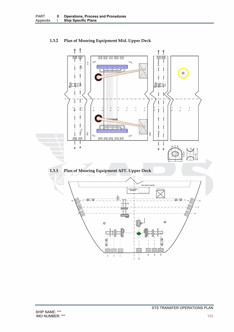
PART B Operations, Process and Procedures Appendix I Ship Specific Plans
STS TRANSFER OPERATIONS PLAN SHIP NAME: *** IMO NUMBER: *** 153
1.3.2 Plan of Mooring Equipment Mid. Upper Deck
1.3.3 Plan of Mooring Equipment AFT. Upper Deck

PART B Operations, Process and Procedures Appendix I Ship Specific Plans
STS TRANSFER OPERATIONS PLAN SHIP NAME: ***
154 IMO NUMBER: ***
1.4 List of Personnel, Location Responsibilities, Emergencies Table 11
Rank Location Responsibility Emergency POAC *** Ref. 2.3.6.2.1 ***
Master *** Overall in charge (2.3.6.2.1) Overall in charge
Chief Officer *** *** *** Second Officer *** *** *** Third Officer *** *** *** Fourth Officer *** *** *** Chief Engineer *** *** *** Second Engineer *** *** *** Third Engineer *** *** *** Fourth Engineer *** *** *** Deck Ratings *** *** *** Engine ratings *** *** *** STS Superintendent *** Ref. Section 4.5 *** Lightering Coordinator *** *** *** Mooring Master *** *** *** Other Relevant Information ***

PART B Operations, Process and Procedures Appendix I Ship Specific Plans
STS TRANSFER OPERATIONS PLAN SHIP NAME: *** IMO NUMBER: *** 155
1.5 Ship Interest Contacts Table 12
Owner / Manager Contacts Name of Company and Individual to be contacted
Address Details Remarks
Individual *** / Company ***
*** Fax: *** Tel: *** Mobile: *** Fax: *** Telex: *** Inmarsat fax: *** Inmarsat Telex: ***
***
*** *** *** *** *** *** *** *** *** *** *** *** *** *** *** *** *** *** *** *** *** *** *** *** *** *** *** *** *** *** *** *** Charterer ***
P & I Club ***
Agent ***
Miscellaneous: ***

STS TRANSFER OPERATIONS PLAN SHIP NAME: ***
156 IMO NUMBER: ***
Appendix J List of National Operational Contact Points
The following two pages is a verbatim copy of MSC-MEPC.6/Circ.14 dated 31 March 2016.
The user of this template is to use the latest IMO updated “List of National Operational Contact
Points list”
A printed version of the “List of National Operational Contact Points” is to be maintained
onboard the STS ships and should be readily available at all times.
MSC-MEPC.6/Circ.14 31 March 2016
STS TRANSFER OPERATIONS PLAN SHIP NAME: *** IMO NUMBER: *** 157
ANNEX 2
LIST OF NATIONAL OPERATIONAL CONTACT POINTS RESPONSIBLE FOR THE RECEIPT, TRANSMISSION AND PROCESSING OF URGENT REPORTS ON INCIDENTS INVOLVING
HARMFUL SUBSTANCES, INCLUDING OIL FROM SHIPS TO COASTAL STATES
1 The following information is provided to enable compliance with Regulation 37 of MARPOL
Annex I which, inter alia, requires that the Shipboard Oil Pollution Emergency Plan (SOPEP) shall
contain a list of authorities or persons to be contacted in the event of a pollution incident involving
such substances. Requirements for oil pollution emergency plans and relevant oil pollution reporting
procedures are contained in Articles 3 and 4 of the 1990 OPRC Convention.
2 This information is also provided to enable compliance with Regulation 17 of MARPOL
Annex II which, inter alia, requires that the shipboard marine pollution emergency plans for oil
and/or noxious liquid substances shall contain a list of authorities or persons to be contacted in the
event of a pollution incident involving such substances. In this context, requirements for emergency
plans and reporting for hazardous and noxious substances are also contained in Article 3 of the 2000
OPRC-HNS Protocol.
3 Resolution MEPC.54(32), as amended by resolution MEPC.86(44), on the SOPEP Guidelines
and resolution MEPC.85(44), as amended by resolution MEPC.137(53), on the Guidelines for the
development of Shipboard Marine Pollution Emergency Plans for Oil and/or Noxious Liquid
Substances adopted by the IMO require that these shipboard pollution emergency plans should
include, as an appendix, the list of agencies or officials of administrations responsible for receiving
and processing reports. Such list is developed and up-dated by the Organization in compliance with
Article 8 (Reports on incidents involving harmful substances) and Protocol I (Provisions concerning
Reports on Incidents Involving Harmful Substances) of the MARPOL Convention. Under Article 8 of
the MARPOL Convention, each Party to the Convention shall notify the Organization with complete
details of authorities responsible for receiving and processing reports on incidents for circulation to
other Parties and Member States of the Organization. Attention is also drawn to both Guidelines
which stipulate that "in the absence of a listed focal point, or should any undue delay be experienced
in contacting the responsible authority by direct means, the master should be advised to contact the
nearest coastal radio station, designated ship movement reporting station or rescue co-ordination
centre (RCC) by the quickest available means".
4 The "List of national operational contact points responsible for the receipt, transmission and
processing of urgent reports on incidents involving harmful substances, including oil from ships to
coastal States" contained in the circular is updated at the end of each calendar year. This list is an
update of that contained in MSC-MEPC.6/Circ.14 dated 31 December 2015, as amended.
5 The above mentioned “List” is available on the Internet and can be accessed at
http://www.imo.org/OurWork/Circulars/Pages/CP.aspx (or select “National Contacts” link on the
bottom of the IMO homepage). This Internet version is updated on a quarterly basis and includes a
MSC-MEPC.6/Circ. 14 31 March 2016
STS TRANSFER OPERATIONS PLAN SHIP NAME: ***
158 IMO NUMBER: ***
summary indicating which country has submitted changes to its information, since the previous
update.
6 On receipt of this latest version and in order to maintain an accurate list, it is necessary that
Member States check their respective information to ensure that it is correct. Effective 29 February
2008, Member States are requested to directly update their respective information in the Global
Integrated Shipping Information Systems (GISIS) using the reporting facilities of the Contact Points
module.
**

MSC-MEPC.6/Circ.14 Annex 2, page 2
STS TRANSFER OPERATIONS PLAN SHIP NAME: *** IMO NUMBER: *** 159
Changes or Amendments to the
LIST OF NATIONAL OPERATIONAL CONTACT POINTS RESPONSIBLE FOR THE RECEIPT, TRANSMISSION AND PROCESSING OF URGENT REPORTS ON INCIDENTS INVOLVING
HARMFUL SUBSTANCES, INCLUDING OIL FROM SHIPS TO COASTAL STATES
The following updates are based on information from countries that notified us of additions, changes or amendments to MSC-MEPC.6/Circ.14:
Updates as at 31 March 2016
BARBADOS
BRITISH VIRGIN ISLANDS (UNITED KINGDOM)
COOK ISLANDS
CURAÇAO (KINGDOM OF THE NETHERLANDS)
HONG KONG, CHINA
HUNGARY
ICELAND
INDIA
ISRAEL
KAZAKHSTAN
LIBERIA
MARSHALL ISLANDS
MEXICO
MICRONESIA, FEDERATED STATES OF
NETHERLANDS
PAKISTAN
PALAU
PERU
QATAR
ROMANIA
UNITED ARAB EMIRATES
URUGUAY
MSC-MEPC.6/Circ.14 Annex 2, page 2
STS TRANSFER OPERATIONS PLAN SHIP NAME: ***
160 IMO NUMBER: ***
Note: This summary page will appear on the Internet whenever changes or amendments are received by the Secretariat before the printed copy of the list is re-issued.
If there are any changes or additions to entries please advise:
Fax: +44 (0)20 7587 3210
E-mail: [email protected]
***

STS TRANSFER OPERATIONS PLAN SHIP NAME: *** IMO NUMBER: *** 161
PART C Event Log of STS Transfer Operation
SECTION 1 Record of STS Transfer Operations
Records and associated documentation of STS Transfer Operations are to be retained onboard
for at least three years.
1.1 STS Transfer Operation Log1.2 STS Transfer Operations Detailed Log

PART C Operations, Process and Procedures SECTION 1 Record of STS Transfer Operations
STS TRANSFER OPERATIONS PLAN SHIP NAME: ***
162 IMO NUMBER: ***
1.1 STS Transfer Operation Log Table 13
Voy. No. Date Location Other STS Ship Oil Type Remarks
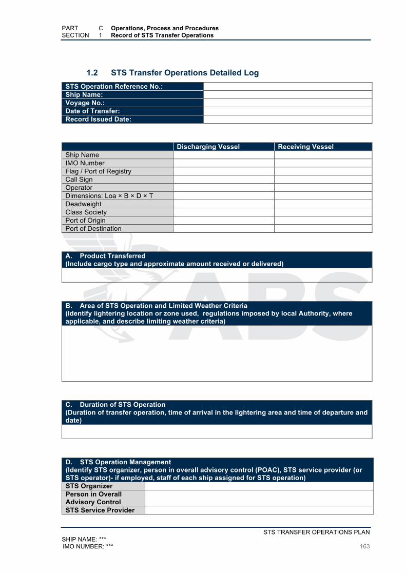
PART C Operations, Process and Procedures SECTION 1 Record of STS Transfer Operations
STS TRANSFER OPERATIONS PLAN SHIP NAME: *** IMO NUMBER: *** 163
1.2 STS Transfer Operations Detailed Log STS Operation Reference No.: Ship Name: Voyage No.: Date of Transfer: Record Issued Date:
Discharging Vessel Receiving Vessel Ship Name IMO Number Flag / Port of Registry Call Sign Operator Dimensions: Loa × B × D × T Deadweight Class Society Port of Origin Port of Destination
A. Product Transferred (Include cargo type and approximate amount received or delivered)
B. Area of STS Operation and Limited Weather Criteria (Identify lightering location or zone used, regulations imposed by local Authority, where applicable, and describe limiting weather criteria)
C. Duration of STS Operation (Duration of transfer operation, time of arrival in the lightering area and time of departure and date)
D. STS Operation Management (Identify STS organizer, person in overall advisory control (POAC), STS service provider (or STS operator)- if employed, staff of each ship assigned for STS operation) STS Organizer Person in Overall Advisory Control
STS Service Provider
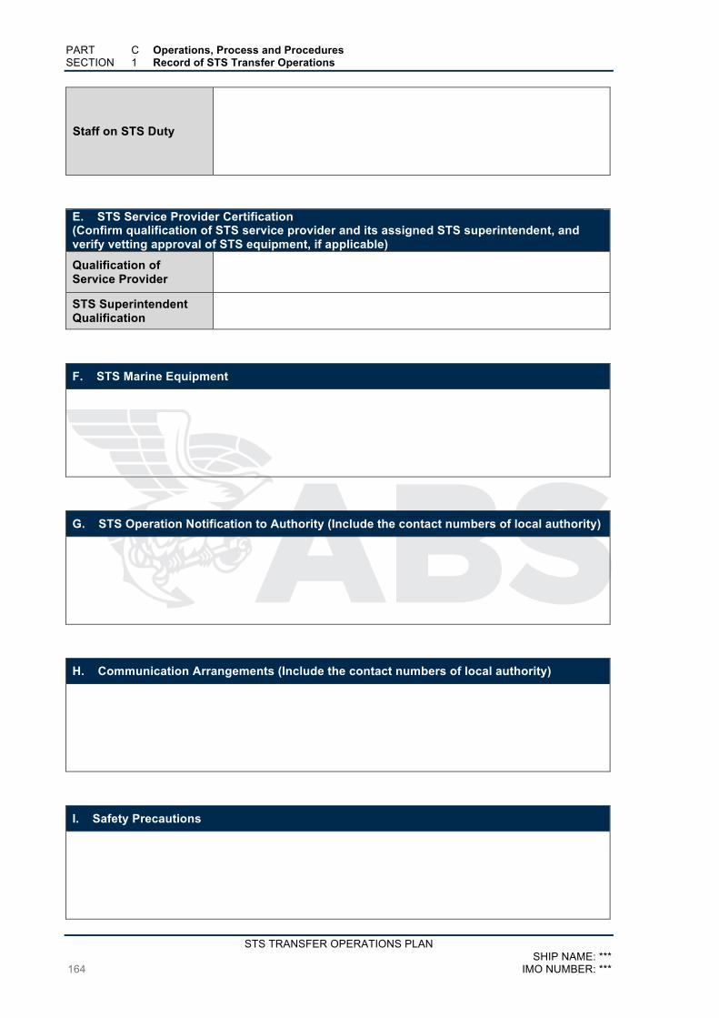
PART C Operations, Process and Procedures SECTION 1 Record of STS Transfer Operations
STS TRANSFER OPERATIONS PLAN SHIP NAME: ***
164 IMO NUMBER: ***
Staff on STS Duty
E. STS Service Provider Certification (Confirm qualification of STS service provider and its assigned STS superintendent, and verify vetting approval of STS equipment, if applicable)
Qualification of Service Provider
STS Superintendent Qualification
F. STS Marine Equipment
G. STS Operation Notification to Authority (Include the contact numbers of local authority)
H. Communication Arrangements (Include the contact numbers of local authority)
I. Safety Precautions

PART C Operations, Process and Procedures SECTION 1 Record of STS Transfer Operations
STS TRANSFER OPERATIONS PLAN SHIP NAME: *** IMO NUMBER: *** 165
J. Contingency Plans
K. Operational Preparations
L. Maneuvering and Mooring
M. Cargo Transfer (Procedures Alongside) (Record the transfer location)
N. Management of Cargo Transfer

PART C Operations, Process and Procedures SECTION 1 Record of STS Transfer Operations
STS TRANSFER OPERATIONS PLAN SHIP NAME: ***
166 IMO NUMBER: ***
O. Unmooring
P. Reporting (Upon completion of transfer operation, notify authority & company, complete cargo transfer document and collect all completed checklists and relevant records.)
Record Approval and Signature (By person in charge of vessel) Name: Rank:
Signature: Date:
Append other relevant records, logs, reports related to the subject STS operation, as deemed
appropriate.
a) Risk Assessment Forms
b) Check List
c) Notification Forms
d) Oil Record Book
e) Rest and Work Hours Record
f) Computer Generated Loading/Discharging Abstract


![Capture One 6.4.3 Release Notes[1]captureintegration.com/download/release/Capture-One-6.4...Capture One 6.4.3 Release Notes(Capture One 6 is a raw converter and workflow software which](https://img.pdfslide.us/doc/110x75/5e85cf35c7959057485b5783/capture-one-643-release-notes1-capture-one-643-release-notescapture-one.jpg)