Embed Size (px)
Citation preview
0
Third Party Protocols Support
ACE3600 System Tools Suite (STS) Version 15.50
6802979C25-H
AB
MOTOROLA, MOTO, MOTOROLA SOLUTIONS and the Stylized
M Logo are trademarks or registered trademarks of Motorola
Trademark Holdings, LLC and are used under license. All other
product or service names are the property of their respective
owners.
Copyright © 2011 Motorola Solutions, Inc. All rights reserved

COMPUTER SOFTWARE COPYRIGHTS
The Motorola products described in this instruction manual may include copyrighted Motorola computer programs stored in semiconductor memories or other media. Laws in the United States and other countries preserve for Motorola certain exclusive rights for copyrighted computer programs including the exclusive right to copy or reproduce in any form the copyrighted computer program. Accordingly, any copyrighted Motorola computer programs contained in the Motorola products described in this manual may not be copied or reproduced in any manner without the express written permission of Motorola. Furthermore, the purchase of Motorola products shall not be deemed to grant either directly or by implication, estoppel, or otherwise, any license under the copyrights, patents or patent applications of Motorola, except for the normal non-exclusive, royalty free license to use that arises by operation of law in the sale of a product.
This media, or Motorola Product, may include Motorola Software, Commercial Third Party Software, and Publicly Available Software.
The Motorola Software that may be included on this media, or included in the Motorola Product, is Copyright © by Motorola Solutions, Inc., and its use is subject to the licenses, terms and conditions of the agreement in force between the purchaser of the Motorola Product and Motorola Solutions, Inc.
The Commercial Third Party Software that may be included on this media, or included in the Motorola Product, is subject to the licenses, terms and conditions of the agreement in force between the purchaser of the Motorola Product and Motorola Solutions, Inc., unless a separate Commercial Third Party Software License is included, in which case, your use of the Commercial Third Party Software will then be governed by the separate Commercial Third Party License.
The Publicly Available Software that may be included on this media, or in the Motorola Product, is listed below. The use of the listed Publicly Available Software is subject to the licenses, terms and conditions of the agreement in force between the purchaser of the Motorola Product and Motorola Solutions, Inc., as well as the terms and conditions of the license of each Publicly Available Software package. Copies of the licenses for the listed Publicly Available Software, as well as all attributions, acknowledgements, and software information details, are included below. Motorola is required to reproduce the software licenses, acknowledgments and copyright notices as provided by the Authors and Owners, thus, all such information is provided in its native language form, without modification or translation.
The Publicly Available Software in the list below is limited to the Publicly Available Software included by Motorola. The Publicly Available Software included by Commercial Third Party Software or Products, that is used in the Motorola Product, are disclosed in the Commercial Third Party Licenses, or via the respective Commercial Third Party Publicly Available Software Legal Notices.
For instructions on how to obtain a copy of any source code being made publicly available by Motorola related to software used in this Motorola Product you may send your request in writing to:
Motorola Solutions, Inc. Open Source Software Management 1301 E. Algonquin Road Schaumburg, IL 60196 USA.
In your request, please include the Motorola Product Name and Version, along with the Publicly Available Software specifics, such as the Publicly Available Software Name and Version.
Note, the source code for the Publicly Available Software may be resident on the Motorola Product Installation Media, or on supplemental Motorola Product Media. Please reference and review the entire Motorola Publicly Available Software Legal Notices and End User License Agreement for the details on location and methods of obtaining the source code.
Note, dependent on the license terms of the Publicly Available Software, source code may not be provided. Please reference and review the entire Motorola Publicly Available Software Legal Notices and End User License Agreement for identifying which Publicly Available Software Packages will have source code provided.
To view additional information regarding licenses, acknowledgments and required copyright notices for Publicly Available Software used in this Motorola Product, please select “Legal Notices” display from the GUI (if applicable), or review the Legal Notices and End User License Agreement File/README, on the Motorola Install Media, or resident in the Motorola Product.
MOTOROLA and the Stylized M logo are registered in the US Patent and Trademark Office. All other trademarks, logos, and service marks ("Marks") are the property of the respective third party owners. You are not permitted to use the Marks without the prior written consent of Motorola or such third party which may own the Marks.
PUBLICLY AVAILABLE SOFTWARE LIST
Name: Info-ZIP
Version: 2005-Feb-10 (2.32, 2.52)
Description: General compression library
Software Site: http://www.info-zip.org/
Source Code: The Source Packages for this software are available from the original Software Site, or may be acquired from Motorola. To obtain the Software from Motorola, please contact Motorola using the methods described in the preamble of this Legal Notices and End User License Agreement Document.
License: This is version 2005-Feb-10 of the Info-ZIP copyright and license. The definitive version of this document should be available at ftp://ftp.info-zip.org/pub/infozip/license.html indefinitely.
Copyright © 1990-2005 Info-ZIP. All rights reserved.
For the purposes of this copyright and license, "Info-ZIP" is defined as the following set of individuals:
Mark Adler, John Bush, Karl Davis, Harald Denker, Jean-Michel Dubois, Jean-loup Gailly, Hunter Goatley, Ed Gordon, Ian Gorman, Chris Herborth, Dirk Haase, Greg Hartwig, Robert Heath, Jonathan Hudson, Paul Kienitz, David Kirschbaum, Johnny Lee, Onno van der Linden, Igor Mandrichenko, Steve P. Miller, Sergio Monesi, Keith Owens, George Petrov, Greg Roelofs, Kai Uwe Rommel, Steve Salisbury, Dave Smith, Steven M. Schweda, Christian Spieler, Cosmin Truta, Antoine Verheijen, Paul von Behren, Rich Wales, Mike White
This software is provided "as is," without warranty of any kind, express or implied. In no event shall Info-ZIP or its contributors be held liable for any direct, indirect, incidental, special or consequential damages arising out of the use of or inability to use this software.
Permission is granted to anyone to use this software for any purpose, including commercial applications, and to alter it and redistribute it freely, subject to the following restrictions:
1. Redistributions of source code must retain the above copyright notice, definition, disclaimer, and this list of conditions.
2. Redistributions in binary form (compiled executables) must reproduce the above copyright notice, definition, disclaimer, and this list of conditions in documentation and/or other materials provided with the distribution. The sole exception to this condition is redistribution of a standard UnZipSFX binary (including SFXWiz) as part of a self-extracting archive; that is permitted without inclusion of this license, as long as the normal SFX banner has not been removed from the binary or disabled.
3. Altered versions--including, but not limited to, ports to new operating systems, existing ports with new graphical interfaces, and dynamic, shared, or static library versions--must be plainly marked as such and must not be misrepresented as being the original source. Such altered versions also must not be misrepresented as being Info-ZIP releases--including, but not limited to, labeling of the altered versions with the names "Info-ZIP" (or any variation thereof, including, but not limited to, different capitalizations), "Pocket UnZip," "WiZ" or "MacZip" without the explicit permission of Info-ZIP. Such altered versions are further prohibited from misrepresentative use of the Zip-Bugs or Info-ZIP e-mail addresses or of the Info-ZIP URL(s).
4. Info-ZIP retains the right to use the names "Info-ZIP," "Zip," "UnZip," "UnZipSFX," "WiZ," "Pocket UnZip," "Pocket Zip," and "MacZip" for its own source and binary releases.
Credits: N/A
Motorola Solutions, Inc. 1301 E. Algonquin Road, Schaumburg, IL 60196 U.S.A.
Table of Contents MODBUS .......................................................................................................................................................... 1
RTU as PLC................................................................................................................................................... 1 Local RTU as PLC Master............................................................................................................................. 2 General System .............................................................................................................................................. 3 MODBUS Drivers.......................................................................................................................................... 4 MODBUS Data Types.................................................................................................................................... 4 Floating Point Numbers ................................................................................................................................ 7 RTU Definitions for MODBUS Support ........................................................................................................ 9
Data Types ..................................................................................................................................................................9 PLC Table ...................................................................................................................................................................9 PLC TCP/IP Access Control Table ...........................................................................................................................12 Port Configuration and Protocol Downloading .........................................................................................................14
Step-by-Step Definitions .............................................................................................................................. 17 RTU as PLC (Connected to Master Computer) – Serial MODBUS..........................................................................17 Local RTU as PLC Master – Serial MODBUS .........................................................................................................17 RTU as PLC (Connected to Master Computer) –MODBUS over TCP/IP ................................................................18 Local RTU as PLC Master ........................................................................................................................................19
RTU as Master – Ladder Diagram Consideration....................................................................................... 20 I/O Link for PLC Data Type Columns ......................................................................................................................21 Static I/O Link for PLC Data Type Columns ............................................................................................................21 Dynamic I/O Link for PLC Data Type Columns.......................................................................................................22 Scan from Rungs .......................................................................................................................................................24
RTU as PLC (Slave) – Mapping of SCADA Element to ACE3600 Database .............................................. 25 PLC Translation File .................................................................................................................................................26 PLC Diagnostics........................................................................................................................................................29
RTU Supported MODBUS Protocol Exceptions (Negative Acknowledges) ................................................ 31 ALLEN BRADLEY PLC-5 PROTOCOL................................................................................................................. 32
Local RTU as PLC Master........................................................................................................................... 33 Allen Bradley PLC–5 Settings ..................................................................................................................... 33
Allen Bradley PLC 5/40 Settings ..............................................................................................................................34 PLC Address for Allen Bradley Protocol ..................................................................................................................35 Data Type Compatibility Between RTU and PLC–5.................................................................................................35 Accessing PLC-5 Controllers ....................................................................................................................................37 RTU Definitions for Allen Bradley PLC–5 Support .................................................................................................38 Step-by-Step Definitions ...........................................................................................................................................41 RTU as Master – Ladder Diagram.............................................................................................................................41
ALLEN BRADLEY SLC 500 PROTOCOL ............................................................................................................. 46 SLC 500 Drivers .......................................................................................................................................... 46 Static I/O Link for PLC Data Type Columns ............................................................................................... 46 Dynamic I/O Link for PLC Data Type Columns.......................................................................................... 47 Accessing SLC 500 Controllers ................................................................................................................... 47

MODBUS
The MODBUS protocol support is applicable to the following situations:
a) Master Configuration: Polling/modifying the database of existing PLC(s). The RTU is defined as a master and the PLC – as a slave. The RTU provides the ability to access the database of a PLC from the application ladder.
b) Slave Configuration: Connecting an RTU as a slave to any SCADA master using the MODBUS protocol. The SCADA central can control all RTUs, as well as all PLCs.
In addition, the RTU communication may be used as a wide area communication network between a MODBUS-based central and its PLCs.
The RTU-to-MODBUS connection is described in this chapter according to the following configurations:
1) RTU as PLC
2) Local RTU as PLC Master
3) General System Configuration
RTU as PLC
The RTU as PLC configuration allows the connection of a MODBUS-based central computer to an MDLC Network, via serial line or TCP/IP media.
The port of this RTU is defined as (Connected to) Master Computer. The central computer can access the database of this RTU that reflects the databases of all RTUs in the field.
In the RTU as PLC, definition of the PLC Table is required.
1
MODBUS
MODBUS PORT
TO MASTER
SCADA CENTRAL(MASTER)
RTUAS PLC
Serial orTCP/IP
RTU
RTU
RTU
MDLC NETWORK
PLC Table
Ind via Port (Name)Connected toRTU (Name)
PLCAddress
0 1 LOCAL RTU AS PLC
PLC#=1
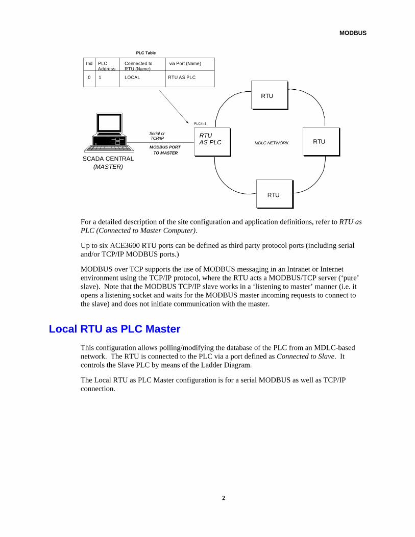
For a detailed description of the site configuration and application definitions, refer to RTU as PLC (Connected to Master Computer).
Up to six ACE3600 RTU ports can be defined as third party protocol ports (including serial and/or TCP/IP MODBUS ports.)
MODBUS over TCP supports the use of MODBUS messaging in an Intranet or Internet environment using the TCP/IP protocol, where the RTU acts a MODBUS/TCP server (‘pure’ slave). Note that the MODBUS TCP/IP slave works in a ‘listening to master’ manner (i.e. it opens a listening socket and waits for the MODBUS master incoming requests to connect to the slave) and does not initiate communication with the master.
Local RTU as PLC Master
This configuration allows polling/modifying the database of the PLC from an MDLC-based network. The RTU is connected to the PLC via a port defined as Connected to Slave. It controls the Slave PLC by means of the Ladder Diagram.
The Local RTU as PLC Master configuration is for a serial MODBUS as well as TCP/IP connection.
2

MODBUS
MODBUS PORTTO SLAVE
Serial or TCP/IP
MDLC NETWORK
RTU
RTU
RTUAS PLCMASTER
PLC
PLC#=1
PLC Table
Ind via Port (Name)Connected to
RTU (Name)
PLC
Address
0 1 LOCAL PLC1
PLC1RTU
MODBUS
For a detailed description of the Site Configuration and Application definitions, refer to Step-by-Step Definitions below.
General System
MDLC NETWORK
MODBUS
RTU 14
MODBUS
RTU 15
MODBUS PORTTO MASTER
SCADA CENTRAL
(MASTER)
RTU
FOX1
RTU
LOCAL
RTU
MODBUS PORTTO SLAVE
PLC1
MODBUS PORTTO SLAVE
PLC1
MODBUS PORTTO SLAVE
PLC2
MODBUS
RTU 13
RTU
FOX5
3
MODBUS
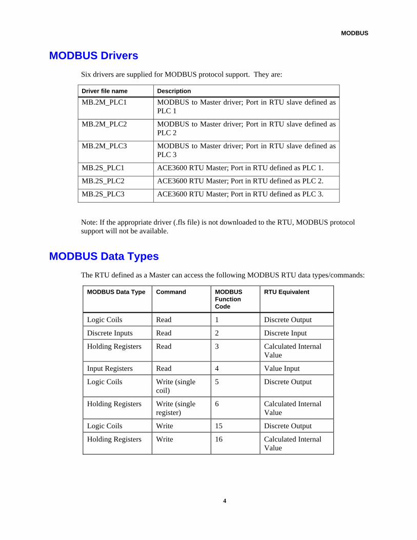
MODBUS Drivers
Six drivers are supplied for MODBUS protocol support. They are:
Driver file name Description
MB.2M_PLC1 MODBUS to Master driver; Port in RTU slave defined as PLC 1
MB.2M_PLC2 MODBUS to Master driver; Port in RTU slave defined as PLC 2
MB.2M_PLC3 MODBUS to Master driver; Port in RTU slave defined as PLC 3
MB.2S_PLC1 ACE3600 RTU Master; Port in RTU defined as PLC 1.
MB.2S_PLC2 ACE3600 RTU Master; Port in RTU defined as PLC 2.
MB.2S_PLC3 ACE3600 RTU Master; Port in RTU defined as PLC 3.
Note: If the appropriate driver (.fls file) is not downloaded to the RTU, MODBUS protocol support will not be available.
MODBUS Data Types
The RTU defined as a Master can access the following MODBUS RTU data types/commands:
MODBUS Data Type Command MODBUS Function Code
RTU Equivalent
Logic Coils Read 1 Discrete Output
Discrete Inputs Read 2 Discrete Input
Holding Registers Read 3 Calculated Internal Value
Input Registers Read 4 Value Input
Logic Coils Write (single coil)
5 Discrete Output
Holding Registers Write (single register)
6 Calculated Internal Value
Logic Coils Write 15 Discrete Output
Holding Registers Write 16 Calculated Internal Value
4

MODBUS
The RTU defined as a MODBUS slave supports the following data types/commands from the MODBUS protocol:
Data Type Command MODBUS Function Code
Logic Coils Read 1
Discrete Inputs Read 2
Holding Registers Read 3
Input Registers Read 4
Logic Coil Write (single coil) 5
Holding Register Write (single register)
6
None Loopback test 8
Logic Coils Write 15
Holding Registers Write 16
– Report Slave ID 17 dec.
By default, ACE3600 uses function code 15 (Multiple Logic Coil Write) and does not use function code 5 (Single Coil Force command). This is true even when writing to a Single Coil.
By default, ACE3600 uses function code 16 (Write Multiple Registers) and does not use function code 6 (Single Register Preset command). This is true even when writing to a Single Register.
In order to enable the Single Coil Force or Single Register Preset command perform the instruction below for each MODBUS port defined as a port connected to a “Slave”:
1. Run the ACE3600 STS.
2. In the site port configuration, click on Advanced Configuration.
3. Select Driver specific parameter #3. This parameter is actually a mask, or set of bits, each of which can be set or unset, each with a different meaning. To enable the Single Coil Force command (function code 5), set the mask to 0x0002 (or decimal value 2). To enable the Single Register Preset command (function code 6), set the mask to 0x0004 (or decimal value 4). If you want to enable BOTH commands, set the mask to 0x0006 (or decimal value 6).
Note: when trying to write to more than one Coil, function code 15 (Multiple Coils Write) is always used, even if the mask 0x0002 is set on.
Note: when trying to write to more than one Register, function code 16 (Multiple register Write) is always used, even if the mask 0x0004 is set on.
Function code 5 (Single Coil Force command) is used if writing exactly one bit and the corresponding mask 0x0002 is set on in Driver specific parameter #3.
5
MODBUS
Function code 6 (Single Register Preset command) is used if writing exactly one register and the corresponding mask 0x0004 is set on in Driver specific parameter #3.
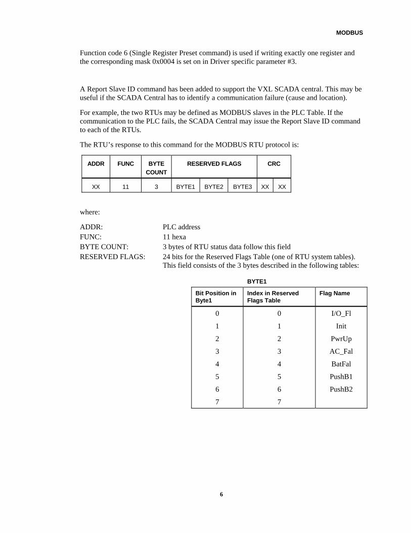
A Report Slave ID command has been added to support the VXL SCADA central. This may be useful if the SCADA Central has to identify a communication failure (cause and location).
For example, the two RTUs may be defined as MODBUS slaves in the PLC Table. If the communication to the PLC fails, the SCADA Central may issue the Report Slave ID command to each of the RTUs.
The RTU’s response to this command for the MODBUS RTU protocol is:
ADDR FUNC BYTE
COUNT
RESERVED FLAGS CRC
XX 11 3 BYTE1 BYTE2 BYTE3 XX XX
where:
ADDR: PLC address FUNC: 11 hexa BYTE COUNT: 3 bytes of RTU status data follow this field RESERVED FLAGS: 24 bits for the Reserved Flags Table (one of RTU system tables).
This field consists of the 3 bytes described in the following tables:
BYTE1
Bit Position in Byte1
Index in Reserved Flags Table
Flag Name
0
1
2
3
4
5
6
7
0
1
2
3
4
5
6
7
I/O_Fl
Init
PwrUp
AC_Fal
BatFal
PushB1
PushB2
6
MODBUS
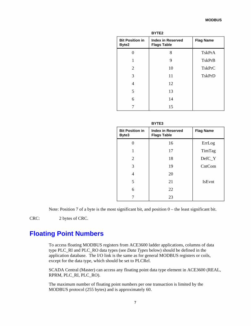
BYTE2
Bit Position in Byte2
Index in Reserved Flags Table
Flag Name
0
1
2
3
4
5
6
7
8
9
10
11
12
13
14
15
TskPrA
TskPrB
TskPrC
TskPrD
BYTE3
Bit Position in Byte3
Index in Reserved Flags Table
Flag Name
0
1
2
3
4
5
6
7
16
17
18
19
20
21
22
23
ErrLog
TimTag
DefC_Y
CntCom
IsEvnt
Note: Position 7 of a byte is the most significant bit, and position 0 – the least significant bit.
CRC: 2 bytes of CRC.
Floating Point Numbers
To access floating MODBUS registers from ACE3600 ladder applications, columns of data type PLC_RI and PLC_RO data types (see Data Types below) should be defined in the application database. The I/O link is the same as for general MODBUS registers or coils, except for the data type, which should be set to PLCRel.
SCADA Central (Master) can access any floating point data type element in ACE3600 (REAL, RPRM, PLC_RI, PLC_RO).
The maximum number of floating point numbers per one transaction is limited by the MODBUS protocol (255 bytes) and is approximately 60.
7
MODBUS
MODBUS protocol does not define floating point data type (4 bytes). To allow floating point data type transfer, each floating point element is represented by 2 integers (2 bytes each).
To enable correct floating point number transfer between the ACE3600 master and the MODBUS slave, or between the MODBUS master and the ACE3600 slave, one should define the format of how the floating point number is transmitted (for each MODBUS port):
1. Run the ACE3600 STS.
2. In the site port configuration, click on Advanced Configuration.
3. Select Driver specific parameter #3. This parameter is actually a mask, or set of bits, each of which can be set or unset, each with a different meaning.
4. To designate that the low order integer register is sent first, followed by the high order register, set the mask to 0x0001 (or decimal value 1). To designate that the high order integer register is sent first, followed by the low order register, unset the mask bit 0x0001 (or decimal value 0). In most cases, the mask 0x0001 should be set on, though the format depends on the vendor.
Recall that other bits in the parameter #3 mask enable/disable other functions. Therefore, care should be taken when changing the value of the bits.
8
MODBUS
RTU Definitions for MODBUS Support
Data Types The following data types may be used when the RTU serves as a master:
• PLC_VI – PLC Value Input. This data type is used to read integer elements from a third party RTU. Each element in a PLC_VI column is a 2-byte signed integer (value). The column length must be defined as the number of the registers that are to be read.
• PLC_VO – PLC Value Output. This data type is used to write into the Holding Registers in a third party RTU.
• PLC_DI – PLC Discrete Input. This data type is used to read 1-bit elements from a third party RTU, such as discrete inputs.
• PLC_DO – PLC Discrete Output. This data type is used to write 1-bit elements into a third party RTU, such as logic coils.
• PLC_RI –PLC Real Input. .This data type is used to read real (floating point) elements from a third party RTU. Each element in PLC_RI is a 4-byte real (floating point) number.
• PLC_RO –PLC Real Output. This data type is used to write real (floating point) elements to a third party RTU. Each element in PLC_RO is a 4-byte real (floating point) number.
PLC Table The PLC Table, one of the System Tables, is used to define the connectivity to the third party PLC units in the system. This table must be defined for:
• The RTU, which is connected to the Master Computer.
• Any RTU, which serves as a PLC master for a PLC connected to one of its ports or connected to one of the other RTUs in the network.
9

MODBUS
This table has five columns as detailed below:
• PLC Address – the address of the PLC RTUs (1–255).
• Connected to RTU (name) – the name of the RTU to which the PLC is connected. Click the arrow to open the list. If the RTU is locally connected to one of the ports of the unit where the PLC Table is to be defined, choose LOCAL from the choice list.
• via Port (name) – the name of the port for connection. Click the arrow to open the list. Choose the same name that was used when the port was defined.
• Slave Addr – The IP address of the TCP/IP slave/PLC (type IPAddrPrm). This column is valid only when the 'Connected to RTU' field is set to ‘Local’ and the ‘via Port’ field is set to PLC1/2/3 (not RTU as PLC.) Otherwise, N/A is displayed.
• Comm Status (Slave) – the status of the slave/PLC (0 = Inactive, 1 = Active) (type int) Note: If Comm Status = 1 and the PLCStt variable returns an error, this indicates a problem with the user application. The status is displayed during the table monitor. The status is N/A when the communication is not MODBUS master over TCP/IP. For details on the possible PLCStt returned errors, see the list from the PLC Status Defines table in Scan from Rungs above.
If the PLC is connected directly via a UART port to the RTU master, then define the Connected to RTU field as LOCAL and the via Port field as PLC 1, 2 or 3.
10

MODBUS
If the PLC is connected to a remote unit which acts as a router, then define the Connected to RTU field as the RTU router Site Name. Assign the name that was used in the Site Table.
If the remote is an RTU which acts as PLC slave, then define the Connected to RTU field as the RTU’s remote Site Name and the via Port field as RTU AS PLC.
11
MODBUS
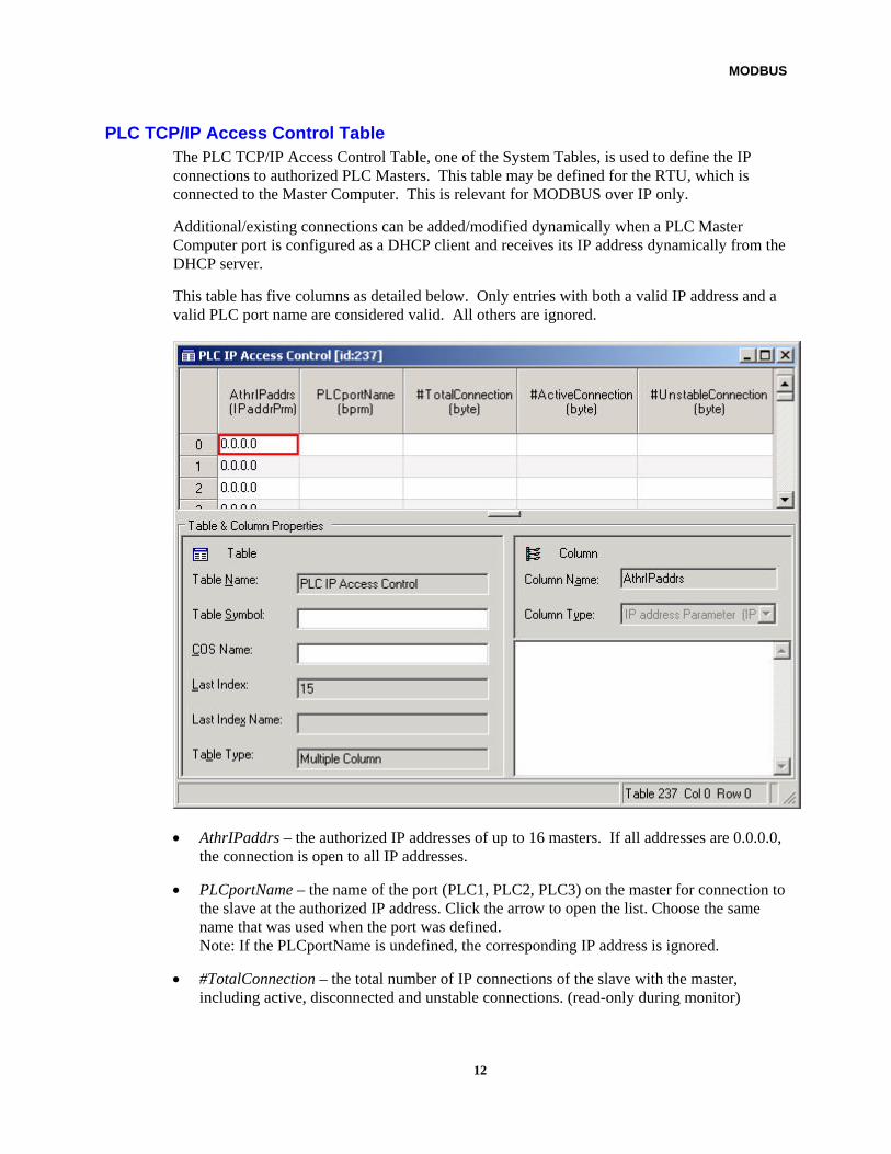
PLC TCP/IP Access Control Table The PLC TCP/IP Access Control Table, one of the System Tables, is used to define the IP connections to authorized PLC Masters. This table may be defined for the RTU, which is connected to the Master Computer. This is relevant for MODBUS over IP only.
Additional/existing connections can be added/modified dynamically when a PLC Master Computer port is configured as a DHCP client and receives its IP address dynamically from the DHCP server.
This table has five columns as detailed below. Only entries with both a valid IP address and a valid PLC port name are considered valid. All others are ignored.
• AthrIPaddrs – the authorized IP addresses of up to 16 masters. If all addresses are 0.0.0.0, the connection is open to all IP addresses.
• PLCportName – the name of the port (PLC1, PLC2, PLC3) on the master for connection to the slave at the authorized IP address. Click the arrow to open the list. Choose the same name that was used when the port was defined. Note: If the PLCportName is undefined, the corresponding IP address is ignored.
• #TotalConnection – the total number of IP connections of the slave with the master, including active, disconnected and unstable connections. (read-only during monitor)
12
MODBUS
• #ActiveConnection – the number of active IP connections of the slave with the master which are connected to the master and have not timed out. (read-only during monitor)
• #UnstableConnection – the number of IP connections of the slave with the master which are unstable (erratic). (read-only during monitor)
Duplicate IP addresses may appear in the PLC TCP/IP Access Control Table. If a duplicate row is deleted, the other rows remain.
Note: If the master port is defined as Ethernet Dynamic LAN, the IP address which is returned by the DHCP server may generate “unauthorized IP address” error messages. In this case, this IP address can be added to the PLC TCP/IP Access Control table via the Application Programmer table monitor, ladder rungs or ‘C’ application.
13
MODBUS
Port Configuration and Protocol Downloading The configuration of an RTU port as a third party protocol port requires two levels of configuration:
• Physical port configuration
• Third party protocol downloading
Port Configuration The PI1, SI1, SI2, PI2 serial/plug-in CPU ports may be defined as a serial Third Party Protocol PLC port. Ports SI1 and SI2 may also be defined as MODBUS ports over TCP/IP (PPP). Ports PI1 and PI2 may also be defined as MODBUS ports over TCP/IP (Ethernet). Port ETH1 may only be defined as an IP MODBUS port over TCP/IP (Ethernet).
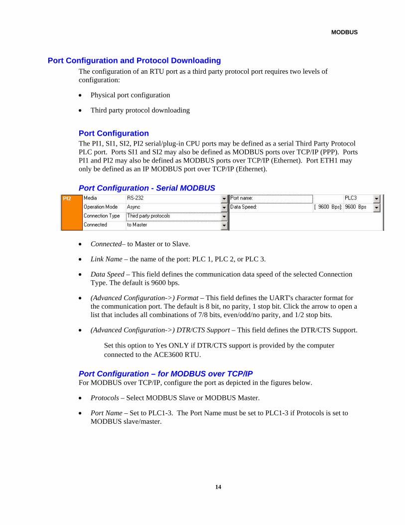
Port Configuration - Serial MODBUS
• Connected– to Master or to Slave.
• Link Name – the name of the port: PLC 1, PLC 2, or PLC 3.
• Data Speed – This field defines the communication data speed of the selected Connection Type. The default is 9600 bps.
• (Advanced Configuration->) Format – This field defines the UART's character format for the communication port. The default is 8 bit, no parity, 1 stop bit. Click the arrow to open a list that includes all combinations of 7/8 bits, even/odd/no parity, and 1/2 stop bits.
• (Advanced Configuration->) DTR/CTS Support – This field defines the DTR/CTS Support.
Set this option to Yes ONLY if DTR/CTS support is provided by the computer connected to the ACE3600 RTU.
Port Configuration – for MODBUS over TCP/IP For MODBUS over TCP/IP, configure the port as depicted in the figures below.
• Protocols – Select MODBUS Slave or MODBUS Master.
• Port Name – Set to PLC1-3. The Port Name must be set to PLC1-3 if Protocols is set to MODBUS slave/master.
14

MODBUS
Port Configuration – RS232 over PPP
Port Configuration - Ethernet 10/100 Base-T - Static LAN
Port Configuration - Ethernet 10/100 Base-T - Dynamic LAN
• Host Full Name – (DHCP Client only) The full name of the port as provided by the DNS Server. The DHCP Server will update the DNS Server when allocating or changing the IP address of that host, keeping it up to date with the recent address of port. If a DHCP Server/router does not support this option, a warning will be logged. For more information on DHCP/DNS, see the ACE3600 STS Advanced Features manual. Note: The MODBUS master should know in advance either the MODBUS slave IP address or its Host Full Name, so that it can connect to a known IP address/Host Full Name of the MODBUS slave. In the case of MODBUS over GPRS (PPP port), the GPRS modem should have a fixed (predefined) IP address and the master should use this IP address to connect to the slave.
• (Advanced Configuration->)Master communication interval – the maximum time in seconds during which a request is expected to be received from the Master. If no communication occurs, the connection is considered unstable. Range 0-86400. Default 0.
• (Advanced Configuration->)Check alive mode – the Check alive mode can be set to Active or Passive: Active – TCP is controlled by the TCP stack of the VxWorks operating system. The MODBUS slave is polled by the master’s connection using the TCP socket’s ‘Check alive’ option. If the idle time on the connection exceeds 60 seconds, a ‘Check alive’ probe is triggered. After the first Check alive probe, a probe is sent every 75 seconds (up to four times), unless a probe response is received. If no probe response is received after sending out four Check alive probes, the TCP connection is dropped. Passive (Default) – TCP is controlled by the application. In this case, the Check alive timeout parameter must be set. The application checks whether the server received any
15
MODBUS
communication until the Check alive timer expires. If the Check alive timeout parameter is set to 0, the check alive mechanism will not be used.
• (Advanced Configuration->)Check alive timeout – the timeout in seconds from the last communication received from a master. If this parameter is 0, a master will always be considered as reachable, once a single reception has been received from it. Otherwise the slave RTU disconnects from the master. Range 0-65535. Default 35. (Relevant only if Check Alive mode is set to Passive.)
• (Advanced Configuration->)TCP listen port – The TCP port used by the Slave for MODBUS communications. Default 502. This default value is standard in TCP. Therefore, it is highly recommended to leave the default as is.
• (Advanced Configuration->Remote TCP port – The TCP port used by the Slave for MODBUS communications. Default 502. This default value is standard in TCP. Therefore, it is highly recommended to leave the default as is.
• (Advanced Configuration->)Connection create timeout – The number of milliseconds the Master will wait after trying to create a connection with the slave. Range 0-65535. Default 500.
• (Advanced Configuration->)Maximum number of connections – The number of entries in the internal connections table. If a new connection is requested when the table is full, the oldest existing connection will be closed and the corresponding entry deleted from the table to make room for the new connection. Range 0-65535. Default 500.
Third Party Protocol Downloading After the configuration of the RTU physical port, according to the type of connection (to Master Computer or PLC), STS provides you with the Downloader utility.
Note: The protocol should be loaded only to the RTUs whose ports have been defined as Connected to Master or Connected to Slave (PLC).
Before downloading the Third Party Protocol file, verify that the required files have been added to the STS site Add-Ons. To do so, click on the General tab in the site view and add the required Third Party Protocol (MODBUS) files from the "config" directory under the STS installation path (e.g. C:\STS1150\Config.)
The Downloader supports downloading to RTUs either locally or remotely via the network. For instructions on how to operate Downloader, see the ACE3600 STS User Guide.
16
MODBUS
Step-by-Step Definitions
RTU as PLC (Connected to Master Computer) – Serial MODBUS Site Configuration
1. Define one of the ports as RS232, Async, Third party protocols, (Connected to) Master.
2. Define the Link Name: PLC 1, PLC 2, or PLC 3.
3. Select the appropriate Data Speed.
4. Click on the Advanced Configuration button, and select (if supported by the Master) the DTR/CTS Support parameter to ‘Yes’.
5. In the Advanced Properties, set the Format parameter to the appropriate format. (The default is 8 bit, no parity, 1 stop bit.)
6. Save the Advanced Configuration and the port configuration in the site.
Third Party Protocol Downloading
1. In the ACE3600 STS Downloader utility, make sure that the ACE3600 STS is connected to the proper site ID/link ID.
2. Select the site configuration to be downloaded to the RTU.
3. Select the appropriate protocol file as described in Third Party Protocol Downloading above.
4. Download the selected files to the RTU.
Application Programmer System Tables
1. In the Application Programmer Database tab, open the PLC Table under System Tables and set the values as follows:
• PLC address as required
• Connected to RTU (Name) LOCAL
• Via Port (Name) RTU AS PLC
2. Define the database tables and process.
Local RTU as PLC Master – Serial MODBUS Site Configuration
1. Define one of the ports as RS232, Async, Third party protocols, (Connected to) Slave.
2. Define the Link Name: PLC 1, PLC 2, or PLC 3.
3. Select the appropriate Data Speed.
17
MODBUS
4. Click on the Advanced Configuration button, and select (if supported by the Slave) the DTR/CTS Support parameter to ‘Yes’.
5. In the Advanced Properties, set the Format parameter to the appropriate format. (The default is 8 bit, no parity, 1 stop bit.)
Third Party Protocol Downloading
1. In the ACE3600 STS Downloader utility, make sure that the ACE3600 STS is connected to the proper site ID/link ID.
2. Select the site configuration to be downloaded to the RTU.
3. Select the appropriate protocol file as described in Third Party Protocol Downloading above.
4. Download the selected files to the RTU.
System Tables
1. In the Application Programmer Database tab, open the PLC Table under System Tables and set the values as follows:
• PLC address: 1
• Connected to RTU (Name): LOCAL
• via Port (Name): PLC1
RTU as PLC (Connected to Master Computer) – MODBUS over TCP/IP Site Configuration
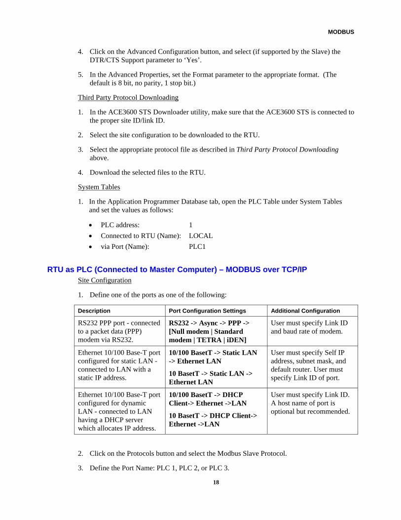
1. Define one of the ports as one of the following:
Description Port Configuration Settings Additional Configuration
RS232 PPP port - connected to a packet data (PPP) modem via RS232.
RS232 -> Async -> PPP -> [Null modem | Standard modem | TETRA | iDEN]
User must specify Link ID and baud rate of modem.
Ethernet 10/100 Base-T port configured for static LAN - connected to LAN with a static IP address.
10/100 BasetT -> Static LAN -> Ethernet LAN
10 BasetT -> Static LAN -> Ethernet LAN
User must specify Self IP address, subnet mask, and default router. User must specify Link ID of port.
Ethernet 10/100 Base-T port configured for dynamic LAN - connected to LAN having a DHCP server which allocates IP address.
10/100 BasetT -> DHCP Client-> Ethernet ->LAN
10 BasetT -> DHCP Client-> Ethernet ->LAN
User must specify Link ID. A host name of port is optional but recommended.
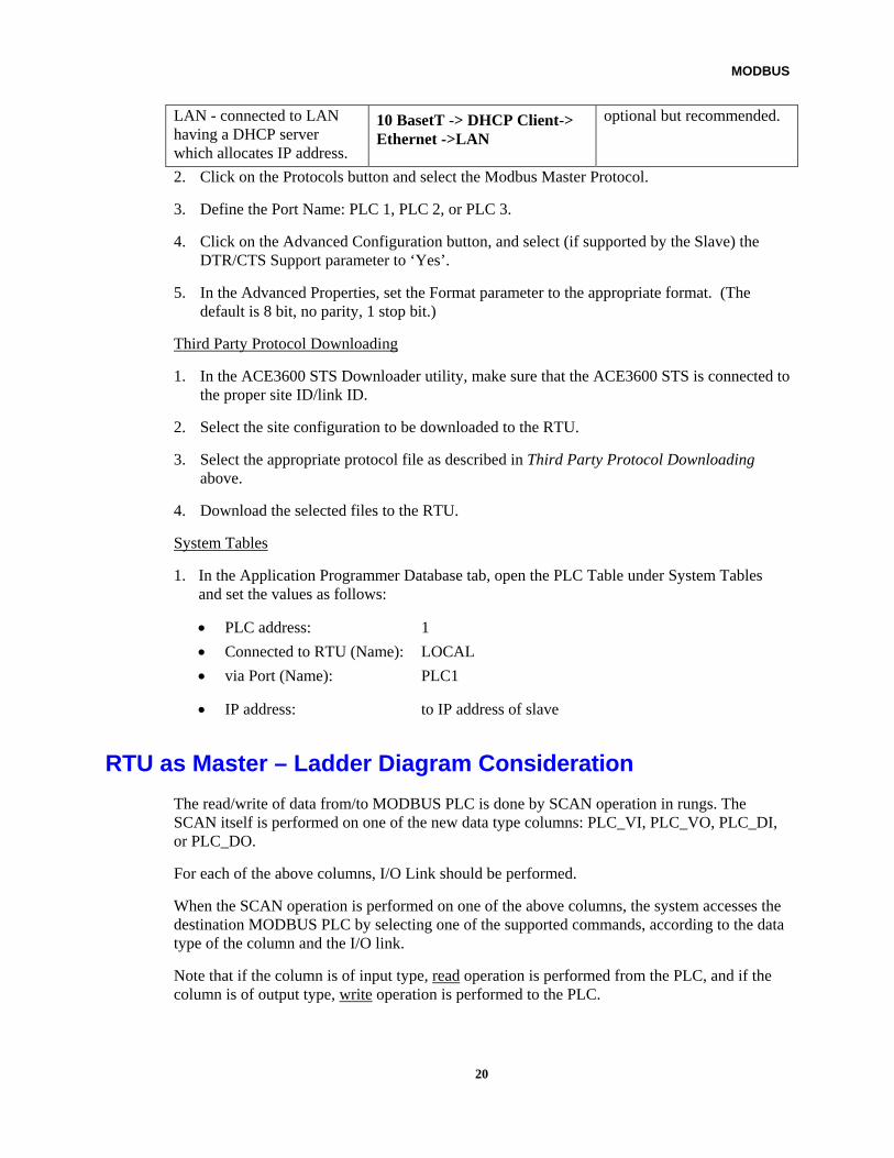
2. Click on the Protocols button and select the Modbus Slave Protocol.
3. Define the Port Name: PLC 1, PLC 2, or PLC 3.
18
MODBUS
4. Click on the Advanced Configuration button, and set the standard MODBUS advanced parameters (described in Appendix A: Site Configuration Parameters in the ACE3600 STS User Guide) and the special MODBUS TCP/IP parameters described in Port Configuration – for MODBUS over TCP/IP above, as necessary. Note: In general, no changes to the default values of the advanced parameters are required.
5. Save the Advanced Configuration and the port configuration in the site.
Third Party Protocol Downloading
1. In the ACE3600 STS Downloader utility, make sure that the ACE3600 STS is connected to the proper site ID/link ID.
2. Select the site configuration to be downloaded to the RTU.
3. Select the appropriate protocol file as described in Third Party Protocol Downloading above.
4. Download the selected files to the RTU.
Application Programmer System Tables
1. In the Application Programmer Database tab, open the PLC Table under System Tables and set the values as follows:
• PLC address as required
• Connected to RTU (Name) LOCAL
• Via Port (Name) RTU AS PLC
2. In the Application Programmer Database tab, open the PLC IP Access Control Table and create an entry for each authorized master and the corresponding PLC port on the slave to which master will connect.
3. Define the database tables and process.
Local RTU as PLC Master - MODBUS over TCP/IP Site Configuration
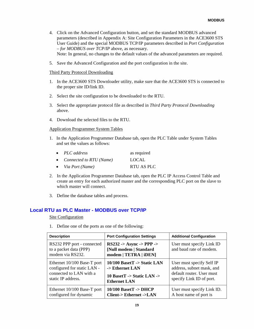
1. Define one of the ports as one of the following:
Description Port Configuration Settings Additional Configuration
RS232 PPP port - connected to a packet data (PPP) modem via RS232.
RS232 -> Async -> PPP -> [Null modem | Standard modem | TETRA | iDEN]
User must specify Link ID and baud rate of modem.
Ethernet 10/100 Base-T port configured for static LAN - connected to LAN with a static IP address.
10/100 BasetT -> Static LAN -> Ethernet LAN
10 BasetT -> Static LAN -> Ethernet LAN
User must specify Self IP address, subnet mask, and default router. User must specify Link ID of port.
Ethernet 10/100 Base-T port configured for dynamic
10/100 BasetT -> DHCP Client-> Ethernet ->LAN
User must specify Link ID. A host name of port is
19
MODBUS
LAN - connected to LAN having a DHCP server which allocates IP address.
10 BasetT -> DHCP Client-> Ethernet ->LAN
optional but recommended.
2. Click on the Protocols button and select the Modbus Master Protocol.
3. Define the Port Name: PLC 1, PLC 2, or PLC 3.
4. Click on the Advanced Configuration button, and select (if supported by the Slave) the DTR/CTS Support parameter to ‘Yes’.
5. In the Advanced Properties, set the Format parameter to the appropriate format. (The default is 8 bit, no parity, 1 stop bit.)
Third Party Protocol Downloading
1. In the ACE3600 STS Downloader utility, make sure that the ACE3600 STS is connected to the proper site ID/link ID.
2. Select the site configuration to be downloaded to the RTU.
3. Select the appropriate protocol file as described in Third Party Protocol Downloading above.
4. Download the selected files to the RTU.
System Tables
1. In the Application Programmer Database tab, open the PLC Table under System Tables and set the values as follows:
• PLC address: 1
• Connected to RTU (Name): LOCAL
• via Port (Name): PLC1
• IP address: to IP address of slave
RTU as Master – Ladder Diagram Consideration
The read/write of data from/to MODBUS PLC is done by SCAN operation in rungs. The SCAN itself is performed on one of the new data type columns: PLC_VI, PLC_VO, PLC_DI, or PLC_DO.
For each of the above columns, I/O Link should be performed.
When the SCAN operation is performed on one of the above columns, the system accesses the destination MODBUS PLC by selecting one of the supported commands, according to the data type of the column and the I/O link.
Note that if the column is of input type, read operation is performed from the PLC, and if the column is of output type, write operation is performed to the PLC.
20
MODBUS
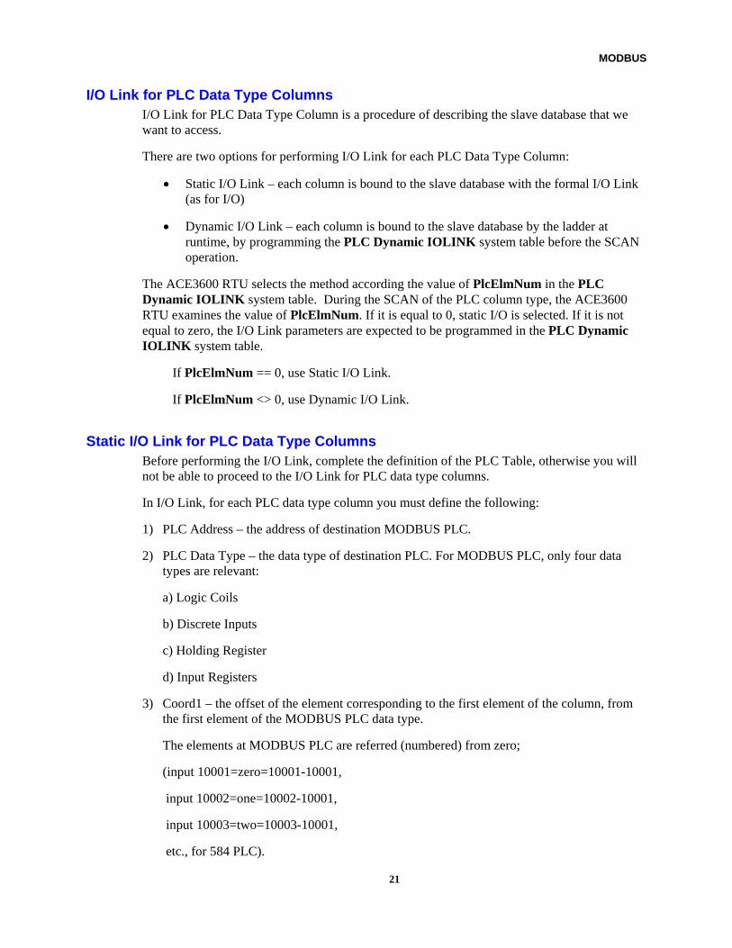
I/O Link for PLC Data Type Columns I/O Link for PLC Data Type Column is a procedure of describing the slave database that we want to access.
There are two options for performing I/O Link for each PLC Data Type Column:
• Static I/O Link – each column is bound to the slave database with the formal I/O Link (as for I/O)
• Dynamic I/O Link – each column is bound to the slave database by the ladder at runtime, by programming the PLC Dynamic IOLINK system table before the SCAN operation.
The ACE3600 RTU selects the method according the value of PlcElmNum in the PLC Dynamic IOLINK system table. During the SCAN of the PLC column type, the ACE3600 RTU examines the value of PlcElmNum. If it is equal to 0, static I/O is selected. If it is not equal to zero, the I/O Link parameters are expected to be programmed in the PLC Dynamic IOLINK system table.
If PlcElmNum == 0, use Static I/O Link.
If PlcElmNum <> 0, use Dynamic I/O Link.
Static I/O Link for PLC Data Type Columns Before performing the I/O Link, complete the definition of the PLC Table, otherwise you will not be able to proceed to the I/O Link for PLC data type columns.
In I/O Link, for each PLC data type column you must define the following:
1) PLC Address – the address of destination MODBUS PLC.
2) PLC Data Type – the data type of destination PLC. For MODBUS PLC, only four data types are relevant:
a) Logic Coils
b) Discrete Inputs
c) Holding Register
d) Input Registers
3) Coord1 – the offset of the element corresponding to the first element of the column, from the first element of the MODBUS PLC data type.
The elements at MODBUS PLC are referred (numbered) from zero;
(input 10001=zero=10001-10001,
input 10002=one=10002-10001,
input 10003=two=10003-10001,
etc., for 584 PLC).
21
MODBUS
If the first element of the column corresponds to input 10003, the PLC Coord1 must be set to 2.
4) Coord1 Len – should be set to 2. The length of Coord1 is 2 bytes.
Note: Do not change the last three lines for coordinates. They are reserved for protocols with more than one coordinate.
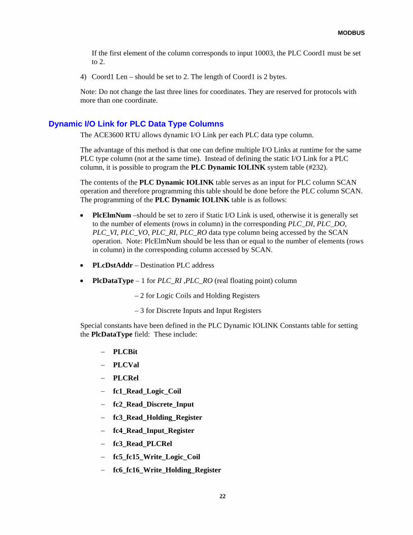
Dynamic I/O Link for PLC Data Type Columns The ACE3600 RTU allows dynamic I/O Link per each PLC data type column.
The advantage of this method is that one can define multiple I/O Links at runtime for the same PLC type column (not at the same time). Instead of defining the static I/O Link for a PLC column, it is possible to program the PLC Dynamic IOLINK system table (#232).
The contents of the PLC Dynamic IOLINK table serves as an input for PLC column SCAN operation and therefore programming this table should be done before the PLC column SCAN. The programming of the PLC Dynamic IOLINK table is as follows:
• PlcElmNum –should be set to zero if Static I/O Link is used, otherwise it is generally set to the number of elements (rows in column) in the corresponding PLC_DI, PLC_DO, PLC_VI, PLC_VO, PLC_RI, PLC_RO data type column being accessed by the SCAN operation. Note: PlcElmNum should be less than or equal to the number of elements (rows in column) in the corresponding column accessed by SCAN.
• PLcDstAddr – Destination PLC address
• PlcDataType – 1 for PLC_RI ,PLC_RO (real floating point) column
– 2 for Logic Coils and Holding Registers
– 3 for Discrete Inputs and Input Registers
Special constants have been defined in the PLC Dynamic IOLINK Constants table for setting the PlcDataType field: These include:
− PLCBit
− PLCVal
− PLCRel
− fc1_Read_Logic_Coil
− fc2_Read_Discrete_Input
− fc3_Read_Holding_Register
− fc4_Read_Input_Register
− fc3_Read_PLCRel
− fc5_fc15_Write_Logic_Coil
− fc6_fc16_Write_Holding_Register
22
MODBUS
− fc16_Write_PLCRel
• PlcCoordNum – Number of coordinates should be set to 1
• PlcCoord1Len – Should be set to 2. The length of Coord1 is 2 bytes
• PlcCoord1 – Should be set the same as described for "Coord1" in the Static I/O Link section above.
Other fields of the PLC Dynamic IOLINK table are irrelevant for MODBUS protocol and should be ignored.
23
MODBUS
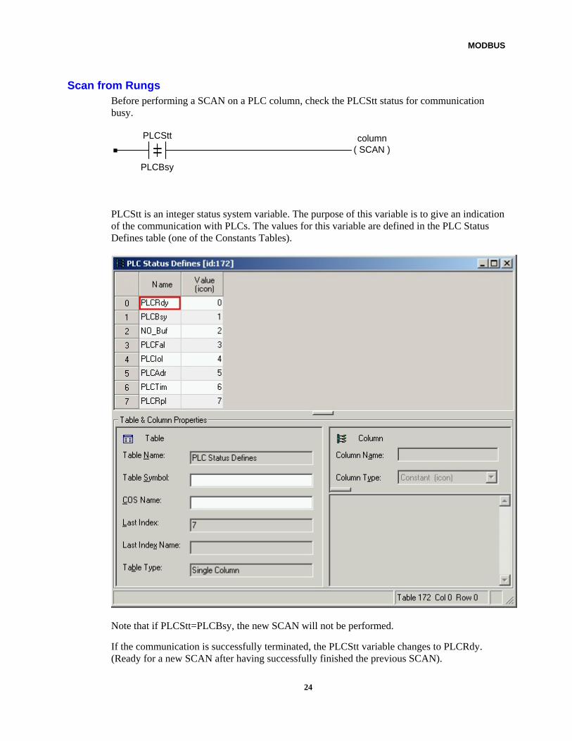
Scan from Rungs Before performing a SCAN on a PLC column, check the PLCStt status for communication busy.
=PLCStt
PLCBsy
column( SCAN )
PLCStt is an integer status system variable. The purpose of this variable is to give an indication of the communication with PLCs. The values for this variable are defined in the PLC Status Defines table (one of the Constants Tables).
Note that if PLCStt=PLCBsy, the new SCAN will not be performed.
If the communication is successfully terminated, the PLCStt variable changes to PLCRdy. (Ready for a new SCAN after having successfully finished the previous SCAN).
24
MODBUS
If the communication is not successfully terminated, the PLCStt variable is changed to one of following values:
NO_Buf – No buffers to perform the communication
PLCFal – Failed to perform the communication
PLCIol – I/O Link Error
PLCAdr – The address does not appear in PLC Table
PLCTim – No response from the PLC slave
PLCRpl – Reply error from PLC slave
During the communication, the PLCStt variable is equal to PLCBsy.
RTU as PLC (Slave) – Mapping of SCADA Element to ACE3600 Database
The ACE3600 RTU defined as a MODBUS slave supports the following data types:
• Logic Coils
• Discrete Inputs
• Holding Registers
• Input Registers
• Real (floating point) Registers
The ACE3600 versatile database enables mapping of various data types to any MODBUS register/bit address (0-65355). However, some SCADA Centrals address the data types according to a predefined register mapping scheme such as:
Logic coils (bit output) range: 00001-10000
Discrete Input status (bit input) range: 10001-30000
Input registers range: 30001-40000
Holding (output) registers range: 40001-49999
The ACE3600 user database is accessible (for MODBUS read/write operation) from the SCADA using the MODBUS protocol.
ACE3600 data is mapped into the MODBUS database by using the following default formula, where Z (=0-31) is the table number, X (=0-7) is the column number, and Y (=0-249) is the row number:
MODBUS register/bit address = offset + Z*2048 +X*256+Y.
The offset may vary according for different SCADA software. See Offset Note below.
25
MODBUS
By default, the table number (Z) may vary from 0 to 31. If a higher numbered user table must be accessed, then do the following:
1) In the ACE3600 STS site configuration, modify the Advanced Physical ‘Register map’ parameter for the PLC port configuration to the “table=64 column=8 row=128” value.
2) Use the following formula where the user table number (Z) may vary from 0-63, X (=0-7) is the column number, and Y (=0-127) is the row number.
MODBUS register /bit address = offset + Z*1024 +X*128+Y.
Again, the offset may vary for different SCADA software. See Offset Note below.
Offset Note: There are some SCADA systems for which addressing does not depend on the data type; there is no specific absolute range reference per data type. For such a SCADA, the offset in the equation should be set to 0. For other SCADA software, the offset = 00001, 10001, 30001, and 40001 for logic coil, input status, input register, and holding register data type respectively.
In addition, a “PLC Translation file” add-on to the STS enables access to all data available in ACE3600 database user tables. For information on preparing such a file, see PLC Translation File below.
PLC Translation File The register mapping scheme described above is limiting and does not enable access to all data in the RTU database user tables. An additional mapping on top of the basic register mapping scheme can be defined, based on PLC addresses, or MODBUS function codes, or both.
The PLC Translation file is a text file, created by the user, which defines the additional mapping. When the file is configured and downloaded to the ACE3600 RTU, the additional mapping becomes active.
The following example describes a system for which the PLC Translation File add-on is applicable.
Four totally identical RTUs are accessed by an ACE36000 concentrator. The database for the first RTU is mirrored (reflected) in the ACE3600 by tables (0-31), the second RTU by tables (32-63), the third RTU by tables (64-95) and the fourth RTU by tables (96-127). The four groups of tables are totally identical and reflect the database of the corresponding RTU.
The MODBUS SCADA accesses the RTU by accessing the corresponding table and element in the ACE3600 table.
In addition, on the SCADA, the application engineer would like to define four copies of each element (tag) (per RTU) having the same MODBUS register/bit number. Each tag will appear four times (having the same register/bit number), but with four different MODBUS PLC addresses (1, 2, 3, 4).
A number of problems arise in building such a system:
26
MODBUS
1. The MODBUS to ACE3600 database mapping is limited by the range of tables that can be accessed, because only the first 32 (0<=Z<=31) or 64 (0<=Z<=63) tables can be mapped. See RTU as PLC (Slave) – Mapping of SCADA Element to ACE3600 Database above.
2. The MODBUS register/bit number has a unique mapping to the ACE3600 (z, x, y) element and therefore it cannot be mapped to four different elements on the ACE3600 (representing different RTUs in different tables) with the same register/bit number on the SCADA, as described above. If four elements on the SCADA are defined with the same register/bit number, they will all be mapped to the same (z, x, y) element on the ACE3600.
The solution is to introduce an additional mapping on the top of the register mapping scheme described above using a PLC Translation File.
The PLC Translation File uses the .ini format and includes three sections (one per PLC port) and instructions. It is a text file and can be edited by any text file editor. The file can be built from the example template, Modbus_Example.plc, which is located in the "config" directory under the STS installation path (e.g. C:\STS1150\Config.) Once the file is configured and downloaded to the ACE36000, the additional mapping will become active.
The example PLC Translation File looks as follows, and defines a mapping for the port defined as PLC2:
[MODBUS_CONNECTED_TO_MASTER_COMPUTER_PORT_NAME_PLC1] [MODBUS_CONNECTED_TO_MASTER_COMPUTER_PORT_NAME_PLC2] STATION_TABLE(Z)_OFST_BY_ADDR_1 =0 STATION_TABLE(Z)_OFST_BY_ADDR_2 =32 STATION_TABLE(Z)_OFST_BY_ADDR_3 =64 STATION_TABLE(Z)_OFST_BY_ADDR_4 =96 TABLE(Z)_OFST_BY_FUNCTION_CODE_1 =0 TABLE(Z)_OFST_BY_FUNCTION_CODE_2 =0 TABLE(Z)_OFST_BY_FUNCTION_CODE_3 =0 TABLE(Z)_OFST_BY_FUNCTION_CODE_4 =0 TABLE(Z)_OFST_BY_FUNCTION_CODE_5 =0 TABLE(Z)_OFST_BY_FUNCTION_CODE_6 =0 TABLE(Z)_OFST_BY_FUNCTION_CODE_15=0 TABLE(Z)_OFST_BY_FUNCTION_CODE_16=0 [MODBUS_CONNECTED_TO_MASTER_COMPUTER_PORT_NAME_PLC3]
The MODBUS_CONNECTED_TO_MASTER_COMPUTER_PORT_NAME_PLC1] section represents instructions which are relevant for access via PLC port PLC1. In this example, no instructions are defined in this section.
The MODBUS_CONNECTED_TO_MASTER_COMPUTER_PORT_NAME_PLC2] section represents instructions which are relevant for access via PLC port PLC2. Four offsets are defined based on the PLC address, and eight offsets are defined based on MODBUS function codes.
27
MODBUS
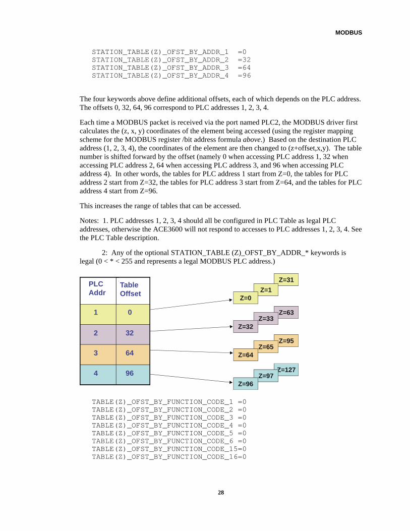
STATION_TABLE(Z)_OFST_BY_ADDR_1 =0 STATION_TABLE(Z)_OFST_BY_ADDR_2 =32 STATION_TABLE(Z)_OFST_BY_ADDR_3 =64 STATION_TABLE(Z)_OFST_BY_ADDR_4 =96
The four keywords above define additional offsets, each of which depends on the PLC address. The offsets 0, 32, 64, 96 correspond to PLC addresses 1, 2, 3, 4.
Each time a MODBUS packet is received via the port named PLC2, the MODBUS driver first calculates the (z, x, y) coordinates of the element being accessed (using the register mapping scheme for the MODBUS register /bit address formula above.) Based on the destination PLC address (1, 2, 3, 4), the coordinates of the element are then changed to (z+offset,x,y). The table number is shifted forward by the offset (namely 0 when accessing PLC address 1, 32 when accessing PLC address 2, 64 when accessing PLC address 3, and 96 when accessing PLC address 4). In other words, the tables for PLC address 1 start from Z=0, the tables for PLC address 2 start from Z=32, the tables for PLC address 3 start from Z=64, and the tables for PLC address 4 start from Z=96.
This increases the range of tables that can be accessed.
Notes: 1. PLC addresses 1, 2, 3, 4 should all be configured in PLC Table as legal PLC addresses, otherwise the ACE3600 will not respond to accesses to PLC addresses 1, 2, 3, 4. See the PLC Table description.
2: Any of the optional STATION_TABLE (Z)_OFST_BY_ADDR_* keywords is legal (0 < * < 255 and represents a legal MODBUS PLC address.)
Z=31
Z=1Z=0
Z=95Z=65
Z=64
Z=127Z=97
Z=96
Z=63Z=33
Z=32
9640
6430
3220
010
Table Offset
PLC addr
96
64
32
0
PLC Addr
Table Offset
4
3
2
1
TABLE(Z)_OFST_BY_FUNCTION_CODE_1 =0 TABLE(Z)_OFST_BY_FUNCTION_CODE_2 =0 TABLE(Z)_OFST_BY_FUNCTION_CODE_3 =0 TABLE(Z)_OFST_BY_FUNCTION_CODE_4 =0 TABLE(Z)_OFST_BY_FUNCTION_CODE_5 =0 TABLE(Z)_OFST_BY_FUNCTION_CODE_6 =0 TABLE(Z)_OFST_BY_FUNCTION_CODE_15=0 TABLE(Z)_OFST_BY_FUNCTION_CODE_16=0
28

MODBUS
The above keywords define an additional offset based on the MODBUS function code on the PLC2 port. In the example file, all offsets are zero, so the final table number (Z) is not impacted by the keywords. If, however, the TABLE(Z)_OFST_BY_FUNCTION_CODE_1 keyword was set to 5, any access done with MODBUS function code 1 via port PLC2 would increase the table number (Z) or shift Z forward by five tables.
Notes: 1. Any of the optional TABLE(Z)_OFST_BY_FUNCTION_CODE_* keywords is legal (*= one of MODBUS function codes 1, 2, 3, 4, 5, 6, 15, 16.)
2: If both types of keywords TABLE(Z)_OFST_BY_FUNCTION_CODE_* and STATION_TABLE(Z)_OFST_BY_ADDR_* are defined – the table number is advanced (shifted) forward by the sum of the two offsets.
The [MODBUS_CONNECTED_TO_MASTER_COMPUTER_PORT_NAME_PLC3] section represents instructions which are relevant for an access done via PLC port PLC3. In this example, no instructions are defined in this section.
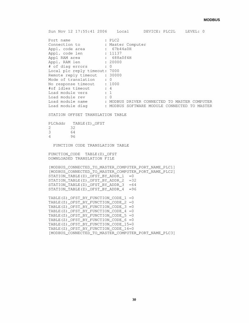
PLC Diagnostics The PLC Translation File which is downloaded to the ACE3600 can be viewed using the STS SW Diagnostics utility (DEVICE= PLC1L for port name PLC1, PLC2L for port name PLC2, PLC3L for port name PLC3, LEVEL=0.) See the example below. For more on the SW Diagnostics utility, see the ACE3600 STS User Guide. For a description of the diagnostics, see the TOSCADA (PLC1L, PLC2L, PLC3L) section of the ACE3600 Software Diagnostic Output and Error Messages Manual.
29
MODBUS
Sun Nov 12 17:55:41 2006 Local DEVICE: PLC2L LEVEL: 0 Port name : PLC2 Connection to : Master Computer Appl. code area : 67b44a0H Appl. code len : 11137 Appl RAM area : 688a0f4H Appl. RAM len : 20000 # of diag errors : 0 Local plc reply timeout: 7000 Remote reply timeout : 30000 Mode of translation : 0 No response timeout : 1000 #of idles timeout : 4 Load module vers : 1 Load module rev : 0 Load module name : MODBUS DRIVER CONNECTED TO MASTER COMPUTER Load module diag : MODBUS SOFTWARE MODULE CONNECTED TO MASTER STATION OFFSET TRANSLATION TABLE PLCAddr TABLE(Z)_OFST 2 32 3 64 4 96 FUNCTION CODE TRANSLATION TABLE FUNCTION_CODE TABLE(Z)_OFST DOWNLOADED TRANSLATION FILE [MODBUS_CONNECTED_TO_MASTER_COMPUTER_PORT_NAME_PLC1] [MODBUS_CONNECTED_TO_MASTER_COMPUTER_PORT_NAME_PLC2] STATION_TABLE(Z)_OFST_BY_ADDR_1 =0 STATION_TABLE(Z)_OFST_BY_ADDR_2 =32 STATION_TABLE(Z)_OFST_BY_ADDR_3 =64 STATION_TABLE(Z)_OFST_BY_ADDR_4 =96 TABLE(Z)_OFST_BY_FUNCTION_CODE_1 =0 TABLE(Z)_OFST_BY_FUNCTION_CODE_2 =0 TABLE(Z)_OFST_BY_FUNCTION_CODE_3 =0 TABLE(Z)_OFST_BY_FUNCTION_CODE_4 =0 TABLE(Z)_OFST_BY_FUNCTION_CODE_5 =0 TABLE(Z)_OFST_BY_FUNCTION_CODE_6 =0 TABLE(Z)_OFST_BY_FUNCTION_CODE_15=0 TABLE(Z)_OFST_BY_FUNCTION_CODE_16=0 [MODBUS_CONNECTED_TO_MASTER_COMPUTER_PORT_NAME_PLC3]
30
MODBUS
31
RTU Supported MODBUS Protocol Exceptions (Negative Acknowledges)
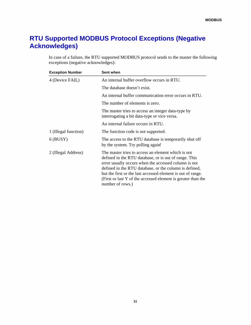
In case of a failure, the RTU supported MODBUS protocol sends to the master the following exceptions (negative acknowledges):
Exception Number Sent when
4 (Device FAIL) An internal buffer overflow occurs in RTU.
The database doesn’t exist.
An internal buffer communication error occurs in RTU.
The number of elements is zero.
The master tries to access an integer data-type by interrogating a bit data-type or vice versa.
An internal failure occurs in RTU.
1 (Illegal function) The function code is not supported.
6 (BUSY) The access to the RTU database is temporarily shut off by the system. Try polling again!
2 (Illegal Address) The master tries to access an element which is not defined in the RTU database, or is out of range. This error usually occurs when the accessed column is not defined in the RTU database, or the column is defined, but the first or the last accessed element is out of range. (First or last Y of the accessed element is greater than the number of rows.)
Allen Bradley PLC-5 Protocol
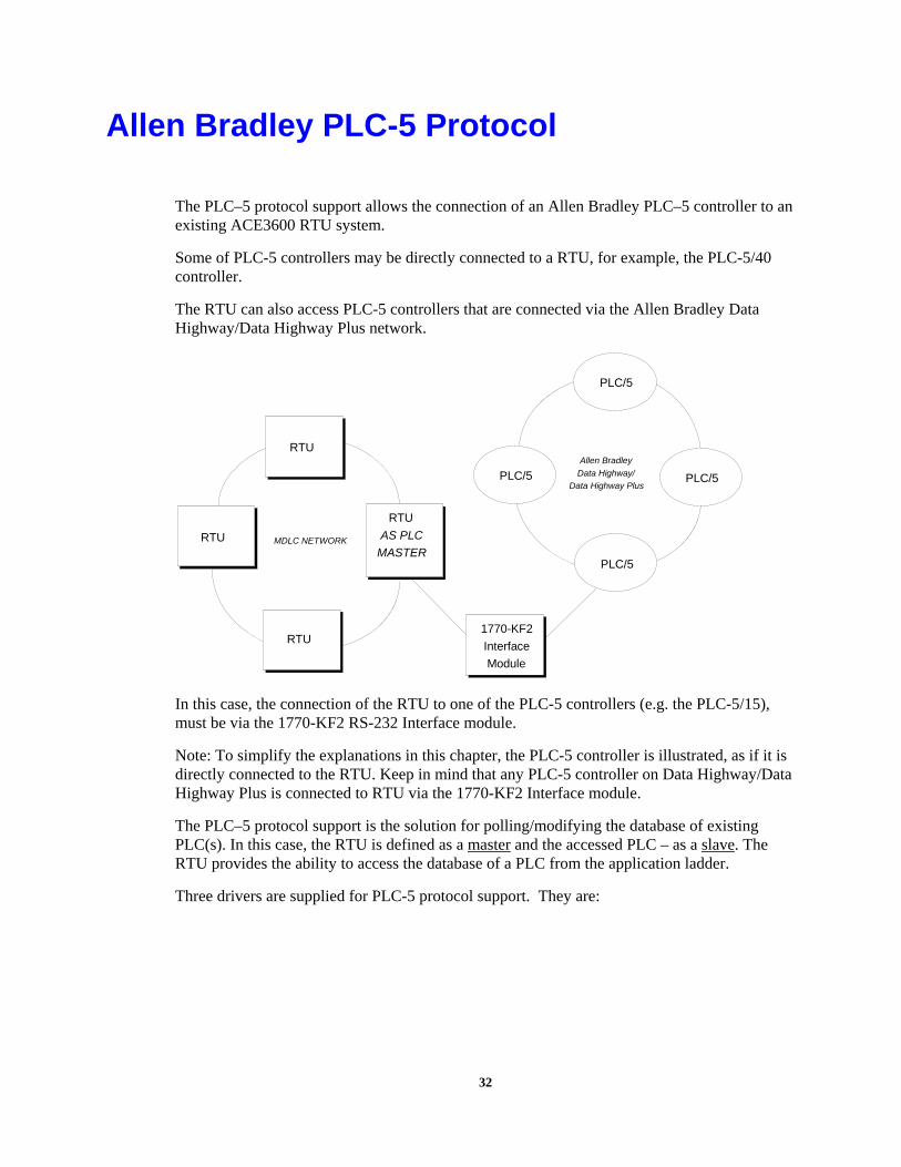
The PLC–5 protocol support allows the connection of an Allen Bradley PLC–5 controller to an existing ACE3600 RTU system.
Some of PLC-5 controllers may be directly connected to a RTU, for example, the PLC-5/40 controller.
The RTU can also access PLC-5 controllers that are connected via the Allen Bradley Data Highway/Data Highway Plus network.
Allen Bradley
Data Highway/
Data Highway PlusPLC/5
PLC/5
PLC/5
PLC/5
MDLC NETWORK
RTU
RTU
AS PLC
MASTER
1770-KF2
Interface
Module
RTU
RTU
In this case, the connection of the RTU to one of the PLC-5 controllers (e.g. the PLC-5/15), must be via the 1770-KF2 RS-232 Interface module.
Note: To simplify the explanations in this chapter, the PLC-5 controller is illustrated, as if it is directly connected to the RTU. Keep in mind that any PLC-5 controller on Data Highway/Data Highway Plus is connected to RTU via the 1770-KF2 Interface module.
The PLC–5 protocol support is the solution for polling/modifying the database of existing PLC(s). In this case, the RTU is defined as a master and the accessed PLC – as a slave. The RTU provides the ability to access the database of a PLC from the application ladder.
Three drivers are supplied for PLC-5 protocol support. They are:
32
1BAllen Bradley PLC-5 Protocol
AB.2S_PLC1 Driver for RTU that is PLC master to Allen Bradley PLC-5, whose Port is defined as PLC 1.
AB.2S_PLC2 Driver for RTU that is PLC master to Allen Bradley PLC-5, whose Port is defined as PLC 2.
AB.2S_PLC3 Driver for RTU that is PLC master to Allen Bradley PLC-5, whose Port is defined as PLC 3.
The RTU-to-PLC-5 connection is described in this section according to the following configuration:
a) Local RTU as PLC master
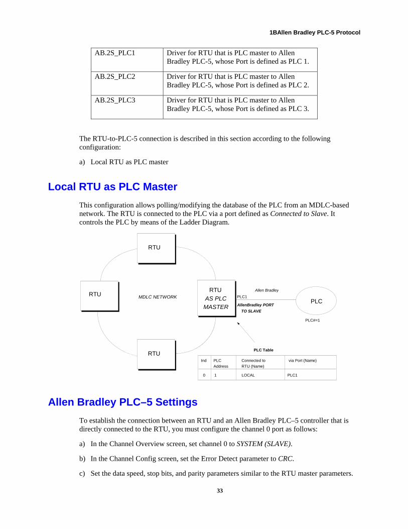
Local RTU as PLC Master
This configuration allows polling/modifying the database of the PLC from an MDLC-based network. The RTU is connected to the PLC via a port defined as Connected to Slave. It controls the PLC by means of the Ladder Diagram.
AllenBradley PORT
TO SLAVE
Allen Bradley
MDLC NETWORK
RTU
RTURTU
AS PLC
MASTERPLC
PLC#=1
PLC Table
Ind via Port (Name)Connected to
RTU (Name)
PLC
Address
0 1 LOCAL PLC1
PLC1
RTU
Allen Bradley PLC–5 Settings
To establish the connection between an RTU and an Allen Bradley PLC–5 controller that is directly connected to the RTU, you must configure the channel 0 port as follows:
a) In the Channel Overview screen, set channel 0 to SYSTEM (SLAVE).
b) In the Channel Config screen, set the Error Detect parameter to CRC.
c) Set the data speed, stop bits, and parity parameters similar to the RTU master parameters.
33
1BAllen Bradley PLC-5 Protocol
d) Set the station address of PLC–5 (it must be in the range of 1 to 254).
Note: These parameters may be set either on-line or off-line.
After setting the channel port, you may connect it to the RTU master PLC port.
If you are using the 1770-KF2 Interface module or another interface module, set the following:
a) Communication=Half-duplex.
b) Set the Error Detect parameter to CRC.
c) Set the data speed, stop bits, and parity parameters similar to the RTU master parameters.
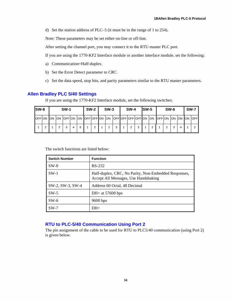
Allen Bradley PLC 5/40 Settings If you are using the 1770-KF2 Interface module, set the following switches:
SW-8 SW-1 SW-2 SW-3 SW-4 SW-5 SW-6 SW-7
OFF ON ON ON OFF ON ON OFF OFF ON ON OFF OFF OFF OFF ON ON OFF ON ON ON ON OFF
1 2 1 2 3 4 5 1 2 1 2 3 1 2 3 1 2 1 2 3 4 1 2
The switch functions are listed below:
Switch Number Function
SW-8 RS-232
SW-1 Half-duplex, CRC, No Parity, Non-Embedded Responses, Accept All Messages, Use Handshaking
SW-2, SW-3, SW-4 Address 60 Octal, 48 Decimal
SW-5 DH+ at 57600 bps
SW-6 9600 bps
SW-7 DH+
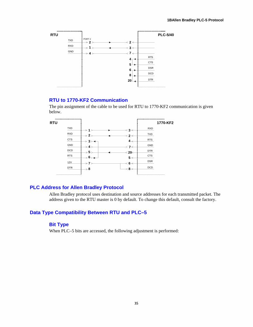
RTU to PLC-5/40 Communication Using Port 2 The pin assignment of the cable to be used for RTU to PLC5/40 communication (using Port 2) is given below.
34
1BAllen Bradley PLC-5 Protocol
TXD
RXD
GND
2
1
4
2
3
7
4
5
6
8
20
RTUPORT 2
PLC-5/40
DSR
CTS
RTS
DCD
DTR
RTU to 1770-KF2 Communication The pin assignment of the cable to be used for RTU to 1770-KF2 communication is given below.
TXD
RXD
DCD
1
2
3
3
2
4
7
20
5
6
RTU 1770-KF2
CTS
DTR
RTS
DSR
DCD
CTS
GND
RTS
12V
DTR
4
5
6
7
8
RXD
TXD
8
GND
PLC Address for Allen Bradley Protocol Allen Bradley protocol uses destination and source addresses for each transmitted packet. The address given to the RTU master is 0 by default. To change this default, consult the factory.
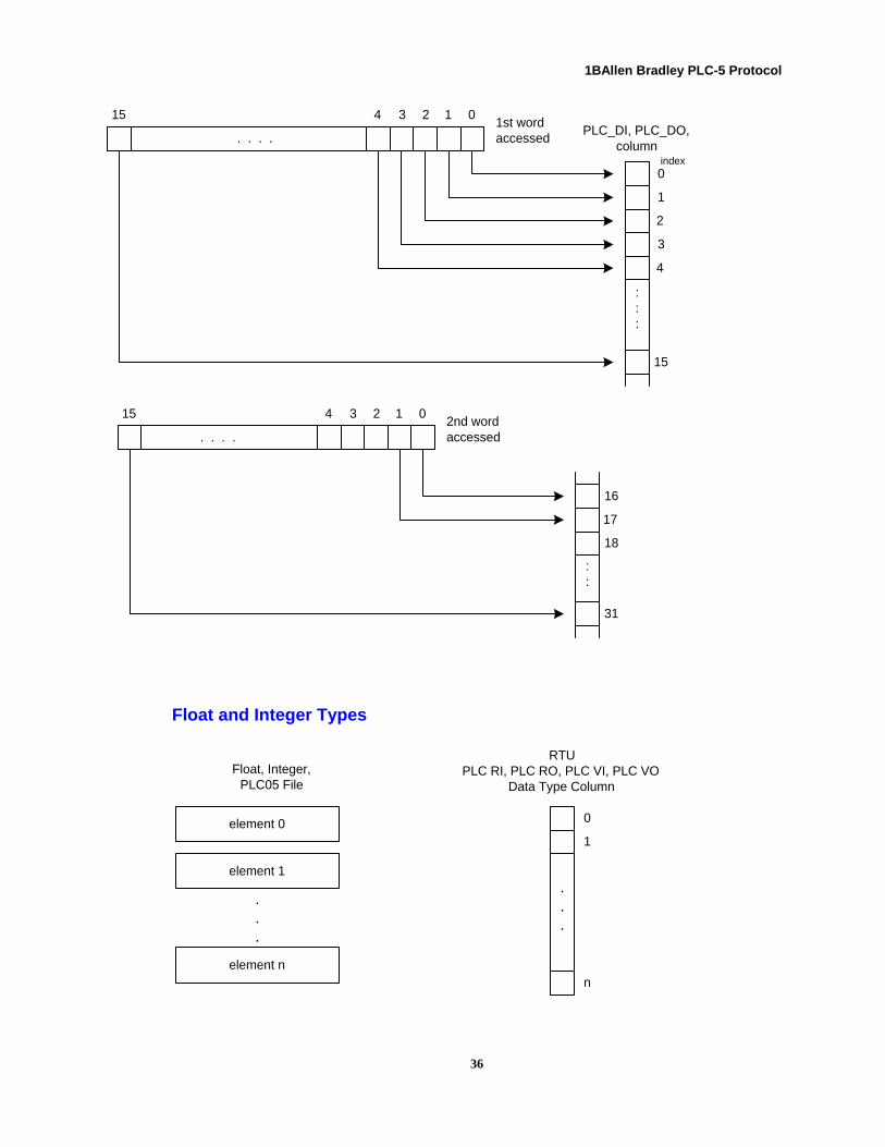
Data Type Compatibility Between RTU and PLC–5
Bit Type When PLC–5 bits are accessed, the following adjustment is performed:
35
1BAllen Bradley PLC-5 Protocol
15 4 3 2 1 0
0
1
2
3
4
15
. . . .
:::
1st wordaccessed
PLC_DI, PLC_DO,column
index
15 4 3 2 1 0
16
17
18
31
. . . .
::
2nd wordaccessed
Float and Integer Types
element 0
element 1
element n
Float, Integer,PLC05 File
.
.
.
.
.
.
0
1
n
RTUPLC RI, PLC RO, PLC VI, PLC VO
Data Type Column
36
1BAllen Bradley PLC-5 Protocol
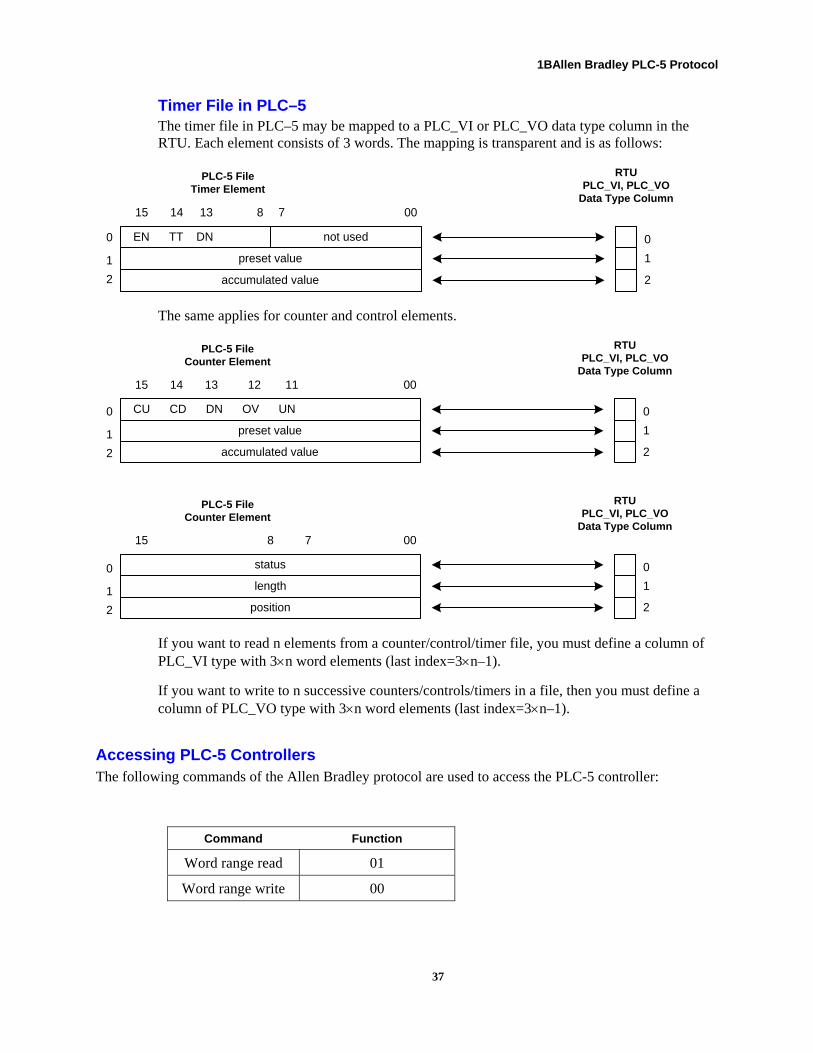
Timer File in PLC–5 The timer file in PLC–5 may be mapped to a PLC_VI or PLC_VO data type column in the RTU. Each element consists of 3 words. The mapping is transparent and is as follows:
preset value
accumulated value
EN TT DN not used
15 14 13 8 7 00
PLC-5 FileTimer Element
0
1
2
RTUPLC_VI, PLC_VO
Data Type Column
0
1
2
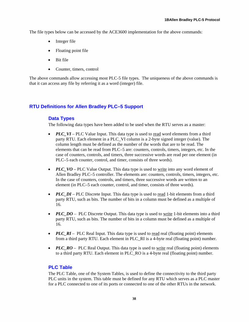
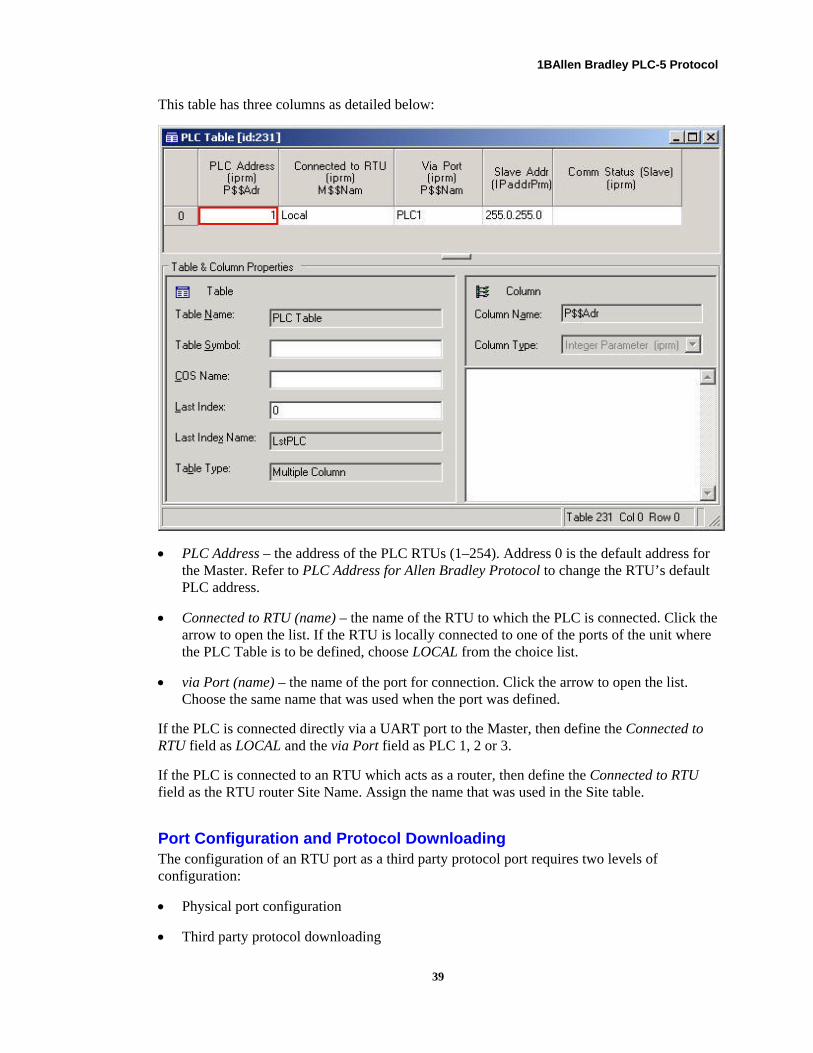
The same applies for counter and control elements.
preset value
accumulated value
CU CD DN OV UN
15 14 13 12 11 00
PLC-5 FileCounter Element
0
1
2
RTUPLC_VI, PLC_VO
Data Type Column
length
position
status
15 8 7 00
PLC-5 FileCounter Element
0
1
2
RTUPLC_VI, PLC_VO
Data Type Column
0
1
2
0
1
2
If you want to read n elements from a counter/control/timer file, you must define a column of PLC_VI type with 3×n word elements (last index=3×n–1).
If you want to write to n successive counters/controls/timers in a file, then you must define a column of PLC_VO type with 3×n word elements (last index=3×n–1).
Accessing PLC-5 Controllers The following commands of the Allen Bradley protocol are used to access the PLC-5 controller:
Command Function
Word range read 01
Word range write 00
37
1BAllen Bradley PLC-5 Protocol
The file types below can be accessed by the ACE3600 implementation for the above commands:
• Integer file
• Floating point file
• Bit file
• Counter, timers, control
The above commands allow accessing most PLC-5 file types. The uniqueness of the above commands is that it can access any file by referring it as a word (integer) file.
RTU Definitions for Allen Bradley PLC–5 Support
Data Types The following data types have been added to be used when the RTU serves as a master:
• PLC_VI – PLC Value Input. This data type is used to read word elements from a third party RTU. Each element in a PLC_VI column is a 2-byte signed integer (value). The column length must be defined as the number of the words that are to be read. The elements that can be read from PLC–5 are: counters, controls, timers, integers, etc. In the case of counters, controls, and timers, three successive words are read per one element (in PLC–5 each counter, control, and timer, consists of three words).
• PLC_VO – PLC Value Output. This data type is used to write into any word element of Allen Bradley PLC–5 controller. The elements are: counters, controls, timers, integers, etc. In the case of counters, controls, and timers, three successive words are written to an element (in PLC–5 each counter, control, and timer, consists of three words).
• PLC_DI – PLC Discrete Input. This data type is used to read 1-bit elements from a third party RTU, such as bits. The number of bits in a column must be defined as a multiple of 16.
• PLC_DO – PLC Discrete Output. This data type is used to write 1-bit elements into a third party RTU, such as bits. The number of bits in a column must be defined as a multiple of 16.
• PLC_RI – PLC Real Input. This data type is used to read real (floating point) elements from a third party RTU. Each element in PLC_RI is a 4-byte real (floating point) number.
• PLC_RO – PLC Real Output. This data type is used to write real (floating point) elements to a third party RTU. Each element in PLC_RO is a 4-byte real (floating point) number.
PLC Table The PLC Table, one of the System Tables, is used to define the connectivity to the third party PLC units in the system. This table must be defined for any RTU which serves as a PLC master for a PLC connected to one of its ports or connected to one of the other RTUs in the network.
38
1BAllen Bradley PLC-5 Protocol
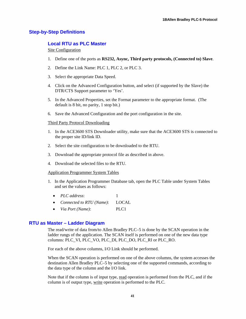
This table has three columns as detailed below:
• PLC Address – the address of the PLC RTUs (1–254). Address 0 is the default address for the Master. Refer to PLC Address for Allen Bradley Protocol to change the RTU’s default PLC address.
• Connected to RTU (name) – the name of the RTU to which the PLC is connected. Click the arrow to open the list. If the RTU is locally connected to one of the ports of the unit where the PLC Table is to be defined, choose LOCAL from the choice list.
• via Port (name) – the name of the port for connection. Click the arrow to open the list. Choose the same name that was used when the port was defined.
If the PLC is connected directly via a UART port to the Master, then define the Connected to RTU field as LOCAL and the via Port field as PLC 1, 2 or 3.
If the PLC is connected to an RTU which acts as a router, then define the Connected to RTU field as the RTU router Site Name. Assign the name that was used in the Site table.
Port Configuration and Protocol Downloading The configuration of an RTU port as a third party protocol port requires two levels of configuration:
• Physical port configuration
• Third party protocol downloading
39

1BAllen Bradley PLC-5 Protocol
Port Configuration Any of the serial/plug-in (PI1, SI1, SI2, PI2) CPU ports may be defined as a Third Party Protocol PLC port.
• Port Advanced Configuration ->DTR/CTS Support – this field defines the DTR/CTS Support. Select this option only if DTR/CTS support is provided by the computer connected to the ACE3600 RTU.
The default values may be changed according to the following:
• Connected to – Slave.
• Port Name – the name of the port: PLC 1, PLC 2, or PLC 3.
• Data Speed – This field defines the communication data speed of the selected Connection Type. The default is 9600 bps.
• (Advanced Configuration->)Format – This field defines the UART's character format for the communication port. The default is 8 bit, no parity, 1 stop bit. Click the arrow to open a list that includes all combinations of 7/8 bits, even/odd/no parity, and 1/2 stop bits.
Third Party Protocol Downloading After configuring the RTU physical port according to the type of connection (to Master Computer or PLC), STS provides you with the Downloader utility.
Note: The protocol should be loaded only to the RTUs whose ports have been defined as Connected to Slave.
Before downloading the Third Party Protocol file, verify that the required files have been added to the STS site Add-Ons. To do so, click on the General tab in the site view and add the required Third Party Protocol files from the "config" directory under the STS installation path (e.g. C:\STS1150\Config.)
The Downloader supports downloading to RTUs either locally or remotely via the network. For instructions on how to operate Downloader, see the ACE3600 STS User Guide.
40
1BAllen Bradley PLC-5 Protocol
Step-by-Step Definitions
Local RTU as PLC Master Site Configuration
1. Define one of the ports as RS232, Async, Third party protocols, (Connected to) Slave.
2. Define the Link Name: PLC 1, PLC 2, or PLC 3.
3. Select the appropriate Data Speed.
4. Click on the Advanced Configuration button, and select (if supported by the Slave) the DTR/CTS Support parameter to ‘Yes’.
5. In the Advanced Properties, set the Format parameter to the appropriate format. (The default is 8 bit, no parity, 1 stop bit.)
6. Save the Advanced Configuration and the port configuration in the site.
Third Party Protocol Downloading
1. In the ACE3600 STS Downloader utility, make sure that the ACE3600 STS is connected to the proper site ID/link ID.
2. Select the site configuration to be downloaded to the RTU.
3. Download the appropriate protocol file as described in above.
4. Download the selected files to the RTU.
Application Programmer System Tables
1. In the Application Programmer Database tab, open the PLC Table under System Tables and set the values as follows:
• PLC address: 1
• Connected to RTU (Name): LOCAL
• Via Port (Name): PLC1
RTU as Master – Ladder Diagram The read/write of data from/to Allen Bradley PLC–5 is done by the SCAN operation in the ladder rungs of the application. The SCAN itself is performed on one of the new data type columns: PLC_VI, PLC_VO, PLC_DI, PLC_DO, PLC_RI or PLC_RO.
For each of the above columns, I/O Link should be performed.
When the SCAN operation is performed on one of the above columns, the system accesses the destination Allen Bradley PLC–5 by selecting one of the supported commands, according to the data type of the column and the I/O link.
Note that if the column is of input type, read operation is performed from the PLC, and if the column is of output type, write operation is performed to the PLC.
41
1BAllen Bradley PLC-5 Protocol
I/O Link for PLC Data Type Columns I/O Link for PLC Data Type Column is a procedure of describing the slave database that we want to access.
There are two options for performing I/O Link for each PLC Data Type Column:
• Static I/O Link – each column is bound to the slave database with the formal I/O Link (as for I/O)
• Dynamic I/O Link – each column is bound to the slave database by the ladder at runtime, by programming the PLC Dynamic IOLINK system table before the SCAN operation.
The ACE3600 RTU selects the method according the value of PlcElmNum in the PLC Dynamic IOLINK system table. During the SCAN of the PLC column type, the ACE3600 RTU examines the value of PlcElmNum. If it is equal to 0, static I/O is selected. If it is not equal to zero, the I/O Link parameters are expected to be programmed in the PLC Dynamic IOLINK system table.
If PlcElmNum == 0, use Static I/O Link.
If PlcElmNum <> 0, use Dynamic I/O Link.
Static I/O Link for PLC Data Type Columns Before performing the I/O Link, complete the definition of the PLC Table, otherwise you will not be able to proceed to the I/O Link for PLC data type columns.
In I/O Link, for each PLC data type column you must define the following:
1) PLC Address – the address of destination Allen Bradley PLC–5. The address range is 1–254. Address 0 is the master address. Refer to PLC Address for Allen Bradley Protocol to change the default PLC address of the master.
2) PLC Data Type – the data type of destination PLC. For Allen Bradley PLC–5, only three data types are relevant:
a) PLCBit – Use this data type when the destination file to read or write is a file of bits.
b) PLCVal – Use this data type when the destination file is of the following type:
• integer
• control
• counter
• timer
• any word type file
c) PLCRel – Use this data type when the destination file is a floating point file.
3) Coord1 – the file number to access.
4) Coord1 Length – should be set to 2. The length of Coord1 is 2 bytes.
42

1BAllen Bradley PLC-5 Protocol
5) PLC Coord2 – the word element number (starting from word 0) in the PLC-5 file which corresponds to the ACE3600 PLC data type column start.
For integer files, PLC Coord2 = integer element number in file.
For floating point files, PLC Coord2 = (floating point element number in file)*2.
For bit files, PLC Coord2 = (bit element number in file)/16.
For counter, timer and control files, PLC Coord2 = (element number in file)*3.
6) Coord2 Length – should be set to 2. The length of Coord2 is 2 bytes.
7) Coord3 – the address (station number) of the Allen Bradley module that is directly connected to the RTU. If a 1770-KF2 or other Interface module is connected to the RTU, then PLC Coord3 should be the address of the interface module. If no interface module is used (the PLC-5 is directly connected to the RTU), then PLC Coord3 should be the address of the PLC-5 controller.
8) Coord3 Length – should be set to 1. The length of Coord3 is 1 byte.
Note: Do not change the last lines for coordinates. It is reserved for protocols with more than one coordinate.
Dynamic I/O Link for PLC Data Type Columns ACE3600 allows dynamic I/O Link per each PLC data type column.
The advantage of this method is that one can define multiple I/O Links at runtime for the same PLC type column (not at the same time). Instead of defining the static I/O Link for a PLC column, it is possible to program the PLC Dynamic IOLINK system table (#232).
The contents of the PLC Dynamic IOLINK table serves as an input for PLC column SCAN operation and therefore programming this table should be done before the PLC column SCAN. The programming of the PLC Dynamic IOLINK table is as follows:
• PlcElmNum –should be set to zero if Static I/O Link is used, otherwise it is generally set to the number of elements (rows in column) in the corresponding PLC_DI, PLC_DO, PLC_VI, PLC_VO, PLC_RI, PLC_RO data type column being accessed by the SCAN operation. Note: PlcElmNum should be less than or equal to the number of elements (rows in column) in the corresponding column accessed by SCAN.
• PLcDstAddr – PLC Address – the address of the destination Allen Bradley PLC–5. The address range is 1–254. Address 0 is the master address. Refer to PLC Address for Allen Bradley Protocol to change the default PLC address of the master.
• PlcDataType – should be set to 1.
• PlcCoordNum – number of coordinates; should be set to 3.
• PlcCoord1Len – should be set to 2. The length of Coord1 is 2 bytes.
• PlcCoord1 - the file number to access.
43
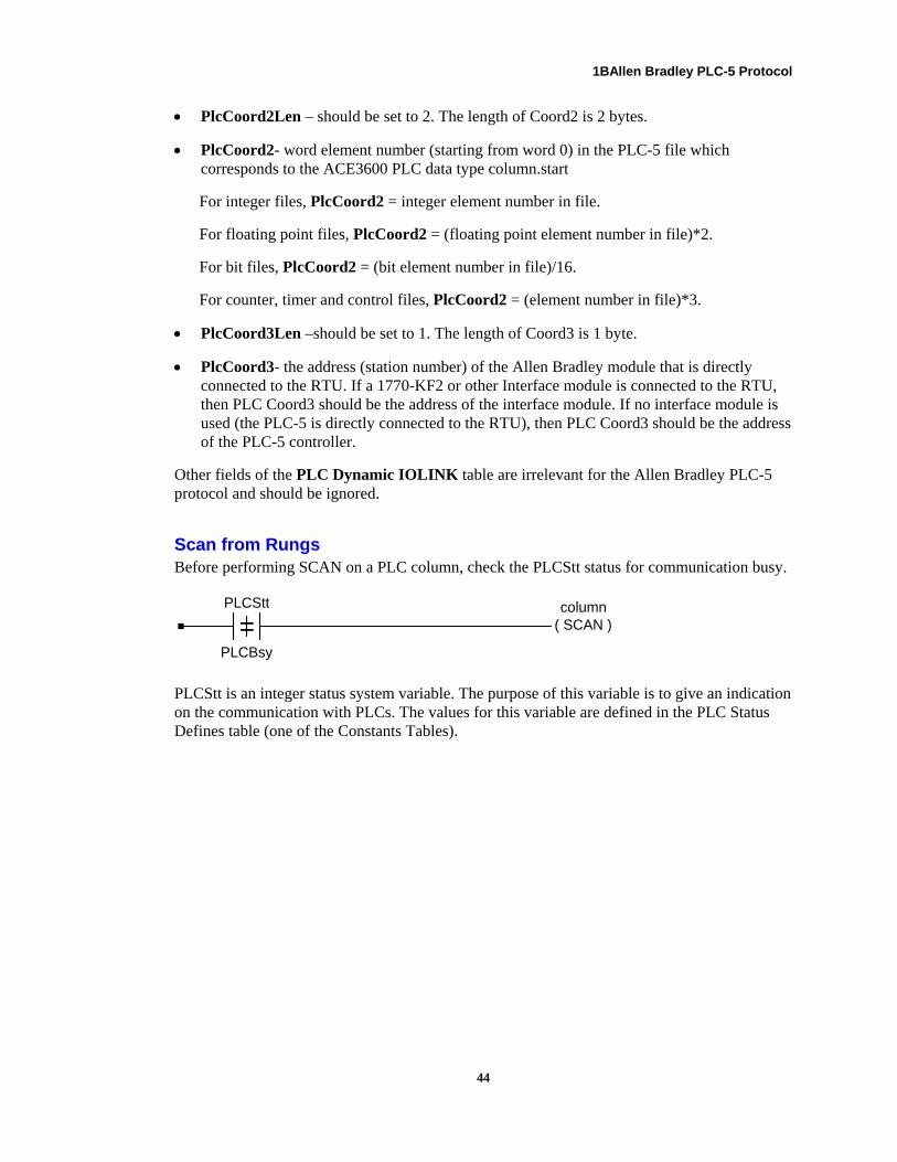
1BAllen Bradley PLC-5 Protocol
• PlcCoord2Len – should be set to 2. The length of Coord2 is 2 bytes.
• PlcCoord2- word element number (starting from word 0) in the PLC-5 file which corresponds to the ACE3600 PLC data type column.start
For integer files, PlcCoord2 = integer element number in file.
For floating point files, PlcCoord2 = (floating point element number in file)*2.
For bit files, PlcCoord2 = (bit element number in file)/16.
For counter, timer and control files, PlcCoord2 = (element number in file)*3.
• PlcCoord3Len –should be set to 1. The length of Coord3 is 1 byte.
• PlcCoord3- the address (station number) of the Allen Bradley module that is directly connected to the RTU. If a 1770-KF2 or other Interface module is connected to the RTU, then PLC Coord3 should be the address of the interface module. If no interface module is used (the PLC-5 is directly connected to the RTU), then PLC Coord3 should be the address of the PLC-5 controller.
Other fields of the PLC Dynamic IOLINK table are irrelevant for the Allen Bradley PLC-5 protocol and should be ignored.
Scan from Rungs Before performing SCAN on a PLC column, check the PLCStt status for communication busy.
=PLCStt
PLCBsy
column( SCAN )
PLCStt is an integer status system variable. The purpose of this variable is to give an indication on the communication with PLCs. The values for this variable are defined in the PLC Status Defines table (one of the Constants Tables).
44
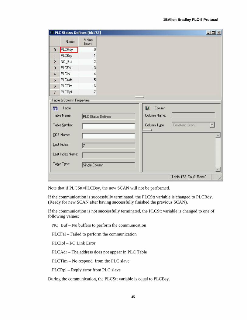
1BAllen Bradley PLC-5 Protocol
45
Note that if PLCStt=PLCBsy, the new SCAN will not be performed.
If the communication is successfully terminated, the PLCStt variable is changed to PLCRdy. (Ready for new SCAN after having successfully finished the previous SCAN).
If the communication is not successfully terminated, the PLCStt variable is changed to one of following values:
NO_Buf – No buffers to perform the communication
PLCFal – Failed to perform the communication
PLCIol – I/O Link Error
PLCAdr – The address does not appear in PLC Table
PLCTim – No respond from the PLC slave
PLCRpl – Reply error from PLC slave
During the communication, the PLCStt variable is equal to PLCBsy.
Allen Bradley SLC 500 Protocol
The SLC 500 family protocol support allows the connection of an Allen Bradley SLC 500, SLC5/01, SLC 5/02, SLC 5/03 and SLC 5/04 controller to an existing ACE3600 RTU system.
Most of the documentation for Allen Bradley PLC-5 controller is applicable for the SLC 500 family; please refer to the Allen Bradley PLC-5 Protocol section in this document. The following are differences which should be noted:
SLC 500 Drivers
Three drivers are supplied for SLC 500 protocol. They are:
SLC.2S_PLC1 Driver for RTU that is PLC master to Allen Bradley SLC 500, whose Port is defined as PLC 1.
SLC.2S_PLC2 Driver for RTU that is PLC master to Allen Bradley SLC 500, whose Port is defined as PLC 2.
SLC.2S_PLC3 Driver for RTU that is PLC master to Allen Bradley SLC 500, whose Port is defined as PLC 3.
Static I/O Link for PLC Data Type Columns
• Coord2 – element number (starting from 0) in the PLC500 file which corresponds to the ACE3600 PLC data type column start.
For integer files, PLC Coord2 = integer element number in file.
For floating point files, PLC Coord2 = floating point element number in file.
For bit files, PLC Coord2 = bit element number in file.
46

2BAllen Bradley SLC 500 Protocol
47
Dynamic I/O Link for PLC Data Type Columns
• PlcCoord2 - element number (starting from word 0) in the PLC500 file which corresponds to the ACE3600 PLC data type column start
For integer files, PlcCoord2 = integer element number in file.
For floating point files, PlcCoord2 = floating point element number in file.
For bit files, PlcCoord2 = bit element number in file.
Accessing SLC 500 Controllers
The following commands of the Allen Bradley protocol are used to access the SLC 500 family of controllers:
Command Function
Protected typed logical read A2
Protected typed logical write AA
The file types below can be accessed by the ACE3600 implementation for the above commands:
• Integer file
• Floating point file
• Bit file
Access to other SLC 5000 data types (counters, timers) is not supported by the ACE3600 RTU. If this is required, the SLC 500 application engineer should copy the unsupported data type to an integer file (which can be accessed by ACE).