Embed Size (px)
Citation preview
3
Airfield Design
Sonoma County Airport Master Plan (May 2007 Draft) 3–1
OVERVIEW Future Airport facility needs are categorized into three major groupings: airfield, passenger terminal, and landside. This chapter evaluates and recommends improvements to the Sonoma County Airport airfield, including runways, taxiways, and navigational aids. Improvements to the airfield will typically enhance safety or improve operational efficiency.
Setting
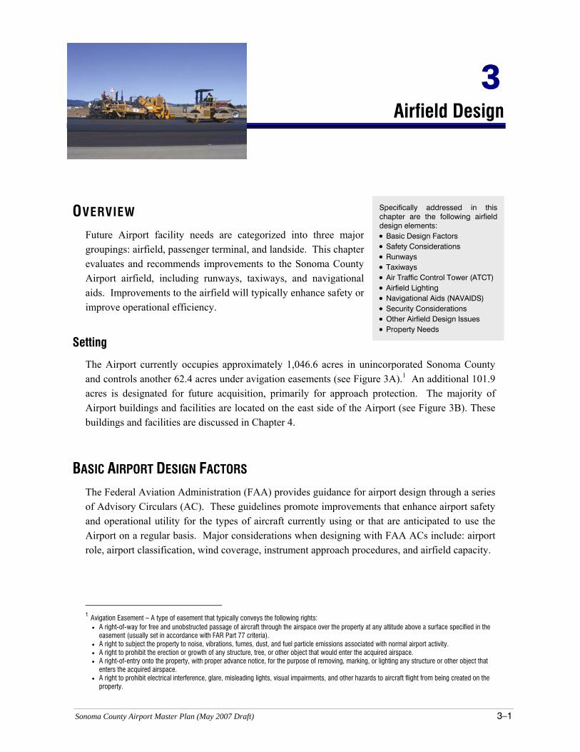
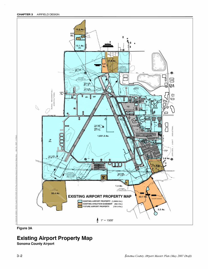
The Airport currently occupies approximately 1,046.6 acres in unincorporated Sonoma County and controls another 62.4 acres under avigation easements (see Figure 3A).1 An additional 101.9 acres is designated for future acquisition, primarily for approach protection. The majority of Airport buildings and facilities are located on the east side of the Airport (see Figure 3B). These buildings and facilities are discussed in Chapter 4.
BASIC AIRPORT DESIGN FACTORS The Federal Aviation Administration (FAA) provides guidance for airport design through a series of Advisory Circulars (AC). These guidelines promote improvements that enhance airport safety and operational utility for the types of aircraft currently using or that are anticipated to use the Airport on a regular basis. Major considerations when designing with FAA ACs include: airport role, airport classification, wind coverage, instrument approach procedures, and airfield capacity.
1 Avigation Easement – A type of easement that typically conveys the following rights:
• A right-of-way for free and unobstructed passage of aircraft through the airspace over the property at any altitude above a surface specified in the easement (usually set in accordance with FAR Part 77 criteria).
• A right to subject the property to noise, vibrations, fumes, dust, and fuel particle emissions associated with normal airport activity. • A right to prohibit the erection or growth of any structure, tree, or other object that would enter the acquired airspace. • A right-of-entry onto the property, with proper advance notice, for the purpose of removing, marking, or lighting any structure or other object that
enters the acquired airspace. • A right to prohibit electrical interference, glare, misleading lights, visual impairments, and other hazards to aircraft flight from being created on the
property.
Specifically addressed in this chapter are the following airfield design elements: • Basic Design Factors • Safety Considerations • Runways • Taxiways • Air Traffic Control Tower (ATCT) • Airfield Lighting • Navigational Aids (NAVAIDS) • Security Considerations • Other Airfield Design Issues • Property Needs
CHAPTER 3 AIRFIELD DESIGN
3–4 Sonoma County Airport Master Plan (May 2007 Draft)
Airport Role
The Airport’s role was discussed in Chapter 2. Sonoma County Airport serves as the region’s principal airport, providing facilities for scheduled airline services and general aviation. It is anticipated that Sonoma County Airport will continue to function as it has in the past, as a nonhub air carrier Airport serving a limited range of scheduled air carrier and commuter airlines and a broad range of general aviation activities.
Airport Classification
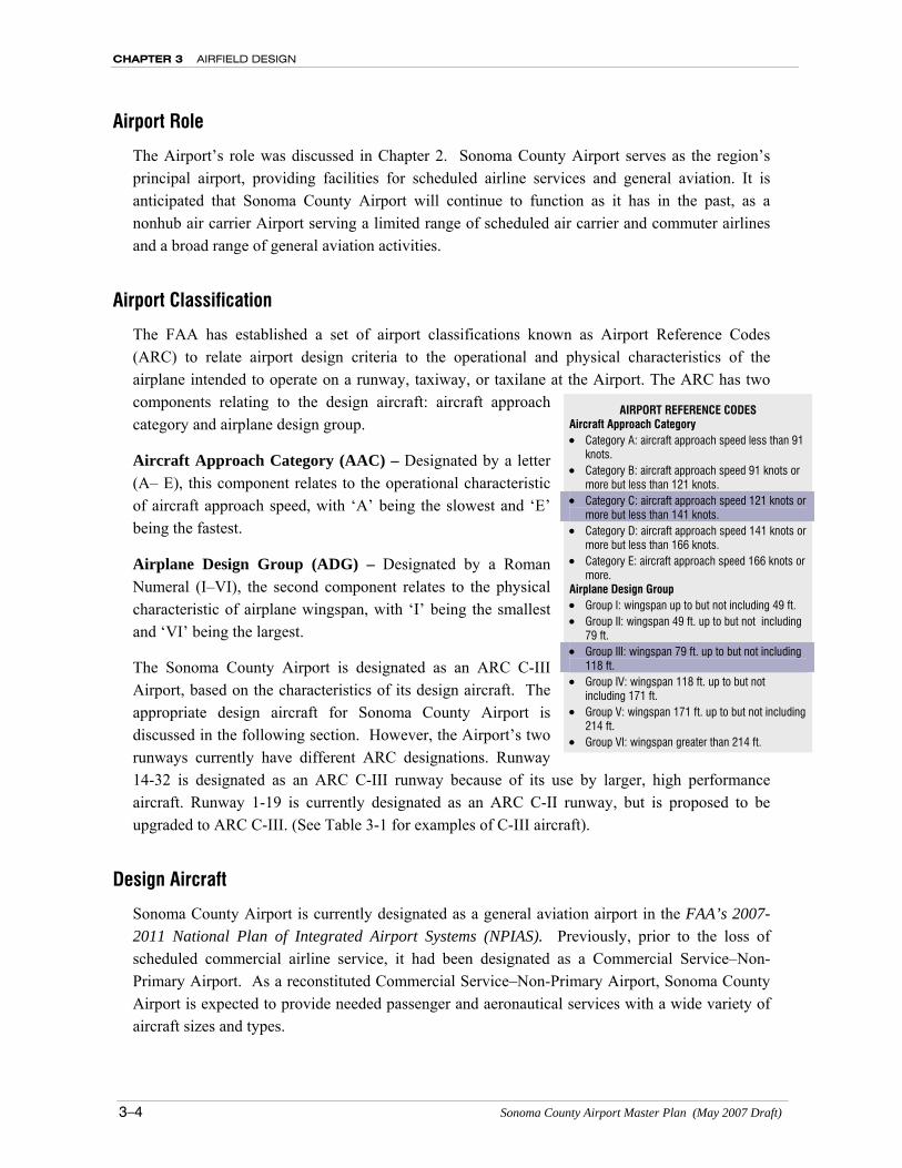
The FAA has established a set of airport classifications known as Airport Reference Codes (ARC) to relate airport design criteria to the operational and physical characteristics of the airplane intended to operate on a runway, taxiway, or taxilane at the Airport. The ARC has two components relating to the design aircraft: aircraft approach category and airplane design group.
Aircraft Approach Category (AAC) – Designated by a letter (A– E), this component relates to the operational characteristic of aircraft approach speed, with ‘A’ being the slowest and ‘E’ being the fastest.
Airplane Design Group (ADG) – Designated by a Roman Numeral (I–VI), the second component relates to the physical characteristic of airplane wingspan, with ‘I’ being the smallest and ‘VI’ being the largest.
The Sonoma County Airport is designated as an ARC C-III Airport, based on the characteristics of its design aircraft. The appropriate design aircraft for Sonoma County Airport is discussed in the following section. However, the Airport’s two runways currently have different ARC designations. Runway 14-32 is designated as an ARC C-III runway because of its use by larger, high performance aircraft. Runway 1-19 is currently designated as an ARC C-II runway, but is proposed to be upgraded to ARC C-III. (See Table 3-1 for examples of C-III aircraft).
Design Aircraft
Sonoma County Airport is currently designated as a general aviation airport in the FAA’s 2007-2011 National Plan of Integrated Airport Systems (NPIAS). Previously, prior to the loss of scheduled commercial airline service, it had been designated as a Commercial Service–Non-Primary Airport. As a reconstituted Commercial Service–Non-Primary Airport, Sonoma County Airport is expected to provide needed passenger and aeronautical services with a wide variety of aircraft sizes and types.
AIRPORT REFERENCE CODES Aircraft Approach Category • Category A: aircraft approach speed less than 91
knots. • Category B: aircraft approach speed 91 knots or
more but less than 121 knots. • Category C: aircraft approach speed 121 knots or
more but less than 141 knots. • Category D: aircraft approach speed 141 knots or
more but less than 166 knots. • Category E: aircraft approach speed 166 knots or
more. Airplane Design Group • Group I: wingspan up to but not including 49 ft. • Group II: wingspan 49 ft. up to but not including
79 ft. • Group III: wingspan 79 ft. up to but not including
118 ft. • Group IV: wingspan 118 ft. up to but not
including 171 ft. • Group V: wingspan 171 ft. up to but not including
214 ft. • Group VI: wingspan greater than 214 ft.
AIRFIELD DESIGN CHAPTER 3
Sonoma County Airport Master Plan (May 2007 Draft) 3-5
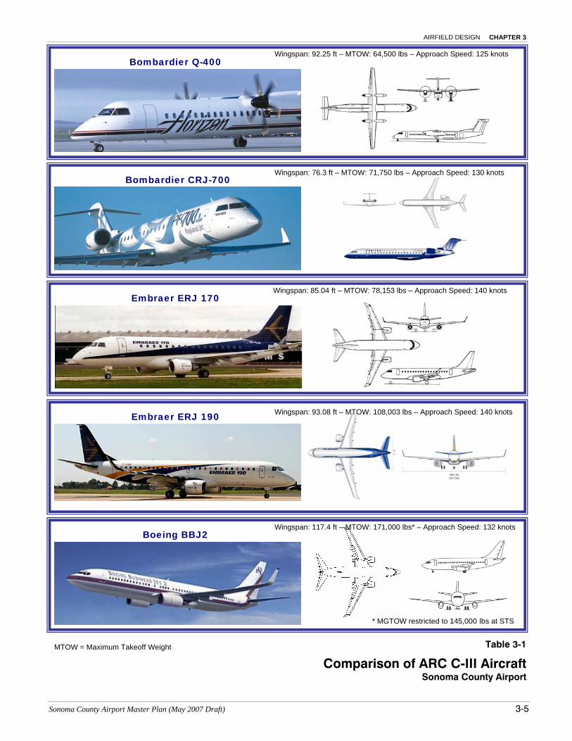
Table 3-1
Comparison of ARC C-III Aircraft Sonoma County Airport
MTOW = Maximum Takeoff Weight
Bombardier CRJ-700
Bombardier Q-400
Wingspan: 76.3 ft – MTOW: 71,750 lbs – Approach Speed: 130 knots
Wingspan: 92.25 ft – MTOW: 64,500 lbs – Approach Speed: 125 knots
Boeing BBJ2
Wingspan: 117.4 ft – MTOW: 171,000 lbs* – Approach Speed: 132 knots
Embraer ERJ 170
Embraer ERJ 190
Wingspan: 85.04 ft – MTOW: 78,153 lbs – Approach Speed: 140 knots
Wingspan: 93.08 ft – MTOW: 108,003 lbs – Approach Speed: 140 knots
* MGTOW restricted to 145,000 lbs at STS
CHAPTER 3 AIRFIELD DESIGN
3–6 Sonoma County Airport Master Plan (May 2007 Draft)
The majority of aircraft operations at Sonoma County Airport are generated by single-engine and twin-engine, general aviation aircraft that fall within Aircraft Approach Categories A and B, and ADG I and II. Most of these aircraft have maximum certificated takeoff weights (MTOW) of 12,500 pounds or less. However, there are a significant number of operations by high performance turbojet and turbofan business aircraft with MTOWs greater than 60,000 pounds. Most of these aircraft are categorized as ARC C-III.
Also included in this category are a number of turboprop and regional jet airline aircraft. Typical aircraft in ARC C-III include the following: Bombardier Q-400 Boeing BBJ Bombardier CRJ-700 Bombardier CRJ-900 Embraer ERJ 170 Embraer ERJ 190
The design aircraft is defined by the FAA as the most critical type of aircraft using the Airport or that is expected to use the Airport on a regular basis (at least 500 annual operations: 250 departures and 250 arrivals).2 It is desirable to design as many of the Airport elements as practical to meet the requirements of the most demanding ARC (i.e., approach speed and wingspan) and runway length requirements. For this reason, the selected design aircraft at Sonoma County Airport is the Embraer ERJ 190. The ERJ 190 was selected as the design aircraft because it is typical of the 98 to106 seat regional jets that are expected to serve the Airport in the future. The characteristics of this aircraft establish the Airport’s ARC as C-III. The ARC C-III is also consistent with the operational characteristics of the majority of larger business/corporate aircraft using the Airport on a regular basis. A discussion on runway length requirements for these aircraft is included in later sections of this chapter.
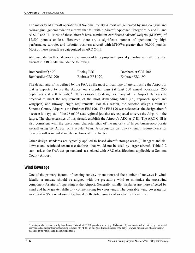
Other design standards are typically applied to based aircraft storage areas (T-hangars and tie-downs) and restricted tenant-use facilities that would not be used by larger aircraft. Table 3-2 summarizes the FAA design standards associated with ARC classifications applicable at Sonoma County Airport.
Wind Coverage
One of the primary factors influencing runway orientation and the number of runways is wind. Ideally, a runway should be aligned with the prevailing wind to minimize the crosswind component for aircraft operating at the Airport. Generally, smaller airplanes are more affected by wind and have greater difficulty compensating for crosswinds. The desirable wind coverage for an airport is 95 percent usability, based on the total number of weather observations.
2 The Airport also receives use by large business aircraft of 90,000 pounds or more (e.g., Gulfstream GV) and occasional operations by commercial airliners used as corporate aircraft weighing in excess of 174,000 pounds (e.g., Boeing Business Jet (BBJ)). However, the numbers of operations by these aircraft do not exceed 500 annual operations.
AIRFIELD DESIGN CHAPTER 3
Sonoma County Airport Master Plan Report (May 2007 Draft) 3-7
Table 3-2 Airport Design Standards
Item FAA Airport Design Standards1 Runway 1-19 Runway 14-32
Airport Reference Code (ARC) C-II C-III C-II C-III
Aircraft Approach Speed (AAS) <141 kts <141 kts <141 kts <141 kts
Airplane Wingspan (ADG) <79 ft. <118 ft. <79 ft. < 118 ft.
Aircraft Weight Group (lbs) >12,500 >12,500 >12,500 >12,500
Approach Visibility Minimums <¾ mile Visual or ≥¾ mile
Visual or ≥¾ mile
<¾ mile
Runway Design
Width 100 ft. 100 ft. 100 ft. 150 ft.
Blast Pad Width 120 ft. 140 ft. 120 ft. 150 ft/ 200 ft
Length beyond Runway End 150 ft. 200 ft. 150 ft. 150 ft/ 200 ft
RSA Width 500 ft. 500 ft. 400 ft.11 500 ft.11
Length beyond Runway End 1,000 ft. 1,000 ft. 1,000 ft. 1,000 ft.12
Obstacle Free Zone2
Shape3 C C A C
Width (W) 400 ft. 400 ft. 400 ft. 400 ft.
Vertical Height (H) 4, 5 /Slope6 53 ft. / 6:1 NA/NA NA/NA 49 ft./ 6:1
OFA Width 800 ft. 800 ft. 800 ft. 800 ft.
Length beyond Runway End 1,000 ft. 1,000 ft. 1,000 ft. 1,000 ft.12
Gradient (maximum) 1.5% 1.5% 1.5% 1.5%
Runway Setbacks: From Runway Centerline to:
Parallel Taxiway Centerline 7 400 ft. 400 ft. NA 400 ft. Hold Line 250 ft. 250 ft. 250 ft. 250 ft.
Aircraft Parking Line 500 ft. 500 ft. * *
Building Restriction Line 8 495 ft. 745 ft. 400 ft. 750 ft.
Helipad for:
Small Helicopters (≤6,000 lbs.) 500 ft. 500 ft. 500 ft. 500 ft.
Medium Helicopters (≤12,000 lbs.) 500 ft. 500 ft. 500 ft. 500 ft.
Heavy Helicopters (>12,000 lbs.) 700 ft. 700 ft. 700 ft. 700 ft.
Taxiway Design
Width 35 ft. 50 ft. 50 ft. 50 ft.
Safety Area Width 79 ft. 118 ft. 79 ft. 118 ft.
Taxiway and Taxilane Setbacks
From Taxiway Centerline to:
Parallel Taxiway/Taxilane 9 105 ft. 152 ft. NA >152 ft.
Fixed or Movable Object 66 ft. 93 ft. 66 ft. >93 ft.
From Taxilane Centerline to:
Fixed or Movable Object 58 ft. 81 ft. 58 ft. ** 1 Source: FAA Advisory Circular 150/5300-13, Change 10, Airport Design (September 2006) 2 Object Free Zone normally extends 200 feet beyond end of runway; additional length required for runways with approach light systems. 3 Runway Obstacle Free Zone Cross Section Shapes: 4 Height increases 3 feet per 1,000 feet of airport elevation 5 Indicated dimensions for runways with approach visibility minimums <3/4 mile are for Category I instrument runways. Criteria for Category II and Category III runways are more restrictive 6 Maximum of 0.8% in first and last quarters of runway. 7 Indicated runway separation is for planning purposes. FAA air traffic control criteria permit simultaneous operations by light, single-engine propeller airplanes with runways as close as 300 feet apart and by twin-engine propeller airplanes with runway separation of 500 feet (FAA Order 7110.65N). 8 The FAA no longer has fixed-distance standards for the BRL Location. The indicated setback distances are based on providing 7:1 transitional slope and RVZ and protected areas clearance over a 35-foot building situated at the same base elevation as the adjacent runway and can be adjusted in accordance with local conditions. 9 Assumes same size airplane uses both taxiway and adjacent taxilane. Distance can be reduced if secondary taxiway is limited to use by smaller airplanes. 10 For runways with approach visibility minimums of ¾ mile or more, but less than 1 mile, runway protection zone dimensions are 1,000 feet width at inner end, 1,510 feet width at outer end, and a length of 1,700 feet. 11 For Airport Reference Code C-I and C-II, a runway safety area width of 400 feet is permissible, but must be 500 feet for ARC C-III. 12 At approach end of Runway 32; 941 feet * Refer to Taxiway Centerline to fixed or moveable object setback ** Design varies within individual building areas
CHAPTER 3 AIRFIELD DESIGN
3–8 Sonoma County Airport Master Plan (May 2007 Draft)
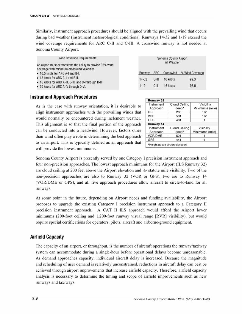
Similarly, instrument approach procedures should be aligned with the prevailing wind that occurs during bad weather (instrument meteorological conditions). Runways 14-32 and 1-19 exceed the wind coverage requirements for ARC C-II and C-III. A crosswind runway is not needed at Sonoma County Airport.
Instrument Approach Procedures
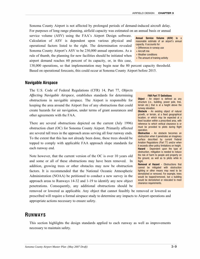
As is the case with runway orientation, it is desirable to align instrument approaches with the prevailing winds that would normally be encountered during inclement weather. This alignment is so that the final portion of the approach can be conducted into a headwind. However, factors other than wind often play a role in determining the best approach to an airport. This is typically defined as an approach that will provide the lowest minimums.
Sonoma County Airport is presently served by one Category I precision instrument approach and four non-precision approaches. The lowest approach minimums for the Airport (ILS Runway 32) are cloud ceiling at 200 feet above the Airport elevation and ½- statute mile visibility. Two of the non-precision approaches are also to Runway 32 (VOR or GPS), two are to Runway 14 (VOR/DME or GPS), and all five approach procedures allow aircraft to circle-to-land for all runways.
At some point in the future, depending on Airport needs and funding availability, the Airport proposes to upgrade the existing Category I precision instrument approach to a Category II precision instrument approach. A CAT II ILS approach would afford the Airport lower minimums (200-foot ceiling and 1,200-foot runway visual range [RVR] visibility), but would require special certifications for operators, pilots, aircraft and airborne/ground equipment.
Airfield Capacity
The capacity of an airport, or throughput, is the number of aircraft operations the runway/taxiway system can accommodate during a single-hour before operational delays become unreasonable. As demand approaches capacity, individual aircraft delay is increased. Because the magnitude and scheduling of user demand is relatively unconstrained, reductions in aircraft delay can best be achieved through airport improvements that increase airfield capacity. Therefore, airfield capacity analysis is necessary to determine the timing and scope of airfield improvements such as new runways and taxiways.
Wind Coverage Requirements:
An airport must demonstrate the ability to provide 95% wind coverage with minimum crosswind velocities. • 10.5 knots for ARC A-I and B-I. • 13 knots for ARC A-II and B-II. • 16 knots for ARC A-III, B-III, and C-I through D-III. • 20 knots for ARC A-IV through D-VI.
Sonoma County Airport All Weather
Runway ARC Crosswind % Wind Coverage
14-32 C-III 16 knots 99.3
1-19 C-II 16 knots 98.0
Runway 32 Instrument Approach
Cloud Ceiling (feet)*
Visibility Minimums (mile)
ILS 200 1/2 VOR 581 1/2 GPS 481 1 Runway 14 Instrument Approach
Cloud Ceiling (feet)*
Visibility Minimums (mile)
VOR/DME 521 1 GPS 441 1
*Height above airport elevation
AIRFIELD DESIGN CHAPTER 3
Sonoma County Airport Master Plan (May 2007 Draft) 3–9
Sonoma County Airport is not affected by prolonged periods of demand-induced aircraft delay. For purposes of long range planning, airfield capacity was estimated on an annual basis or annual service volume (ASV) using the FAA’s Airport Design software. Calculation of ASV is dependent upon various physical and operational factors listed to the right. The determination revealed Sonoma County Airport’s ASV to be 230,000 annual operations. As a rule of thumb, the planning for new facilities should be initiated when airport demand reaches 60 percent of its capacity, or, in this case, 138,000 operations, so that implementation may begin near the 80 percent capacity threshold. Based on operational forecasts, this could occur at Sonoma County Airport before 2015.
Navigable Airspace
The U.S. Code of Federal Regulations (CFR) 14, Part 77, Objects Affecting Navigable Airspace, establishes standards for determining obstructions in navigable airspace. The Airport is responsible for keeping the area around the Airport free of any obstructions that could create hazards for air navigation, under terms of grant assurances and other agreements with the FAA.
There are several obstructions depicted on the current (July 1996) obstruction chart (OC) for Sonoma County Airport. Primarily affected are several tall trees in the approach areas serving all four runway ends. To the extent that this has not already been done, these trees should be topped to comply with applicable FAA approach slope standards for each runway end.
Note however, that the current version of the OC is over 10 years old and some or all of these obstructions may have been removed. In addition, growing trees or other obstacles may now be obstruction factors. It is recommended that the National Oceanic Atmospheric Administration (NOAA) be petitioned to conduct a new survey in the approach areas to Runways 14-32 and 1-19 to identify any new object penetrations. Consequently, any additional obstructions should be removed or lowered as applicable. Any object that cannot feasibly be removed or lowered as prescribed will require a formal airspace study to determine any impacts to Airport operations and appropriate actions necessary to ensure safety.
RUNWAYS This section highlights the design standards applied to each runway as well as improvements necessary to maintain safety.
Annual Service Volume (ASV) is a reasonable estimate of an airport’s annual capacity. It accounts for: Differences in runway use Aircraft mix Weather conditions The amount of training activity
FAR Part 77 Definitions Object - An object is defined as any structure (i.e., building, power pole, tree, terrain etc.) that is at a height above the runway elevation. Obstacle - An existing object of natural growth, or terrain, at a fixed geographical location, or which may be expected at a fixed location within a prescribed area, with reference to which vertical clearance is or must be provided to pilots during flight operation. Obstruction - An obstacle becomes an obstruction when it penetrates an imaginary surface described by current Federal Aviation Regulations (Part 77) and/or when it exceeds other policy limitations on height. Hazard - Dependent upon the type of obstruction, mitigation is needed to reduce the risk of harm to people and property on the ground, as well as to pilots while in flight. Removal of Hazard - Obstructions that cannot be mitigated with obstruction lighting or other means may need to be demolished or removed. For example, trees would be topped/removed, but a building would be demolished or relocated to meet clearance requirements.
CHAPTER 3 AIRFIELD DESIGN
3–10 Sonoma County Airport Master Plan (May 2007 Draft)
Runway 14-32
The primary runway, Runway 14-32, serves all of the Airport’s users. The runway is constructed of asphalt-concrete. For planning purposes, the design aircraft for this runway is the ERJ 190. This aircraft falls within ARC C-III.
The following are key elements associated with Runway 14-32, including: runway length and width, pavement strength, obstacle free zone, runway safety area, runway object free area and the runway protection zones.
Runway Length and Width – Runway length requirements for specific aircraft are primarily dependent upon airfield elevation and temperature (the average high temperature for the hottest month). Runway 14-32 has a length of 5,115 feet, which according to the FAA’s Airport Design program can accommodate roughly 75 percent of airplanes at 65 percent of their useful load (i.e., fuel, passenger, luggage) weighing up to 60,000 pounds over a distance of approximately 1,000 miles. The length of Runway 14-32 is sufficient for the current mix of aircraft operating at the Airport, although it does impose limitations for some jet aircraft, particularly during hot weather or for longer range operations.
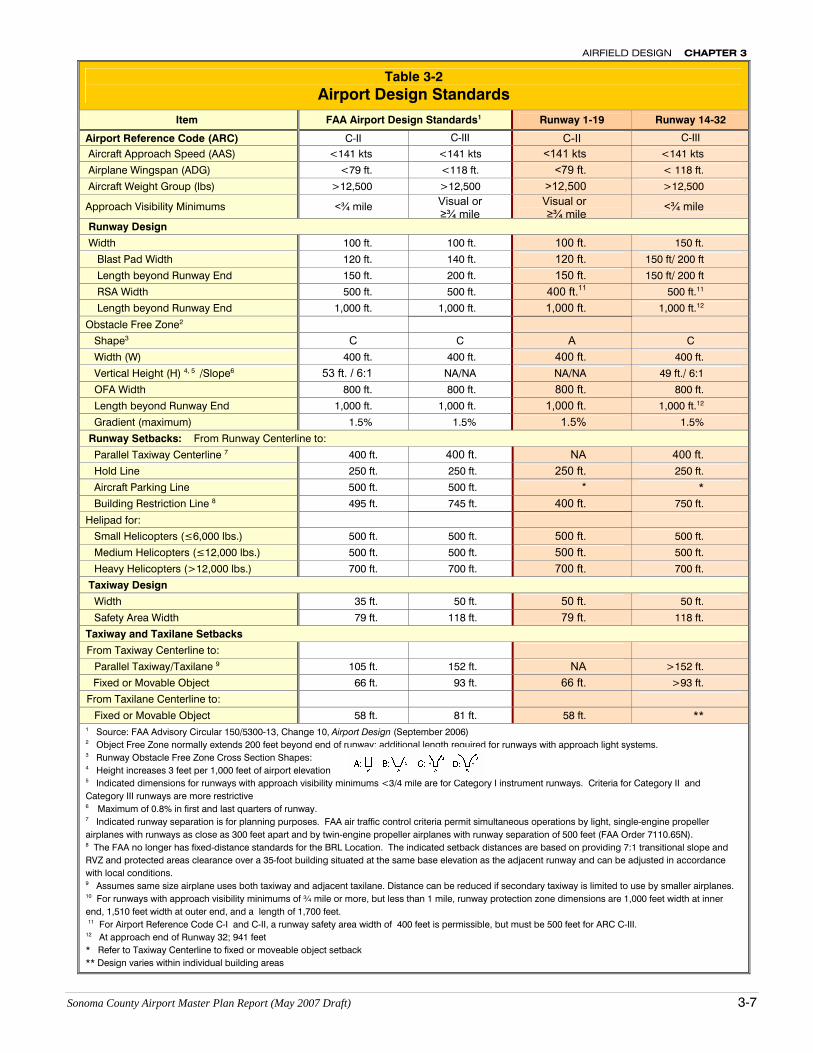
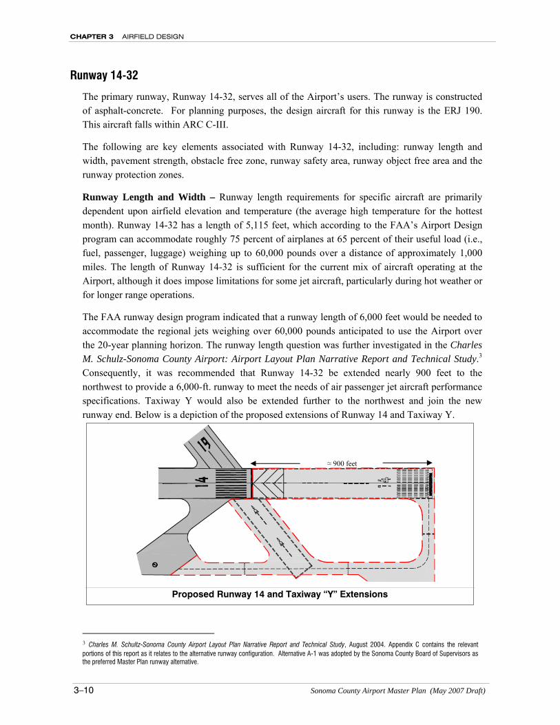
The FAA runway design program indicated that a runway length of 6,000 feet would be needed to accommodate the regional jets weighing over 60,000 pounds anticipated to use the Airport over the 20-year planning horizon. The runway length question was further investigated in the Charles M. Schulz-Sonoma County Airport: Airport Layout Plan Narrative Report and Technical Study.3 Consequently, it was recommended that Runway 14-32 be extended nearly 900 feet to the northwest to provide a 6,000-ft. runway to meet the needs of air passenger jet aircraft performance specifications. Taxiway Y would also be extended further to the northwest and join the new runway end. Below is a depiction of the proposed extensions of Runway 14 and Taxiway Y.
3 Charles M. Schultz-Sonoma County Airport Layout Plan Narrative Report and Technical Study, August 2004. Appendix C contains the relevant portions of this report as it relates to the alternative runway configuration. Alternative A-1 was adopted by the Sonoma County Board of Supervisors as the preferred Master Plan runway alternative.
Proposed Runway 14 and Taxiway “Y” Extensions
≈ 900 feet
AIRFIELD DESIGN CHAPTER 3
Sonoma County Airport Master Plan (May 2007 Draft) 3–11
Land southeast of Runway 32 encompasses part of the precision approach instrument landing system for Runway 32, extending beyond Airport property. The Airport has established approximately 53 acres outside of this area in an avigation easement. A vineyard encompasses this avigation easement and the surrounding area.
Pavement Strength – Airport pavements are constructed to support anticipated aircraft loads over a structural life of 20 years. The reported values are based on an equivalent number of annual departures by the design aircraft. It should be noted that this value is not a physical limitation (i.e., pavement failure will not necessarily occur when a heavier aircraft uses the runway), but is an indication of the pavement’s ability to realize its structural life.
The published weight bearing capacity for Runway 14-32 is 60,000 pounds single-wheel gear configuration, 95,000 dual-wheel gear configuration, and 150,000 pounds dual-tandem-wheel gear configuration. The runway can accommodate occasional use by even heavier aircraft.
As previously described in Chapter 2, annual aircraft operations at Sonoma County Airport have increased partly due to the return of regularly scheduled air carrier service (i.e., Bombardier Aerospace Q-400), and increasing use by business/corporate jet aircraft including larger private jets such as the Gulfstream 500/550 (formerly G-V) and Boeing Business Jets (BBJ/BBJ2).
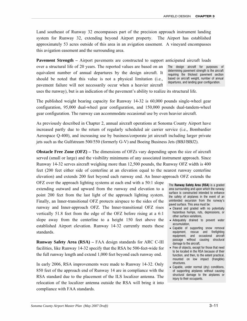
Obstacle Free Zone (OFZ) – The dimensions of OFZs vary depending upon the size of aircraft served (small or large) and the visibility minimums of any associated instrument approach. Since Runway 14-32 serves aircraft weighing more than 12,500 pounds, the Runway OFZ width is 400 feet (200 feet either side of centerline at an elevation equal to the nearest runway centerline elevation) and extends 200 feet beyond each runway end. An Inner-approach OFZ extends the OFZ over the approach lighting systems at each end with a 50:1 slope extending outward and upward from the runway end elevation to a point 200 feet from the last light of the approach lighting system. Finally, an Inner-transitional OFZ protects airspace to the sides of the runway and Inner-approach OFZ. The Inner-transitional OFZ rises vertically 51.8 feet from the edge of the OFZ before rising at a 6:1 slope away from the centerline to a height 150 feet above the established Airport elevation. Runway 14-32 currently meets these standards.
Runway Safety Area (RSA) – FAA design standards for ARC C-III facilities, like Runway 14-32 specify that the RSA be 500-feet-wide for the full runway length and extend 1,000 feet beyond each runway end.
In early 2006, RSA improvements were made to Runway 14-32. Only 850 feet of the approach end of Runway 14 are in compliance with the RSA standard due to the placement of the ILS localizer antenna. The relocation of the localizer antenna outside the RSA will bring it into compliance with FAA standards.
The Runway Safety Area (RSA) is a graded area surrounding and upon which the runway surface is constructed intended to enhance the safety of airplanes in the event of an unintended excursion from the runway’s paved surface. This area must be: • Cleared and graded with no potentially
hazardous humps, ruts, depressions, or other surface variations,
• Adequately drained to prevent water accumulation,
• Capable of supporting snow removal equipment, rescue and firefighting equipment, and occasional aircraft passage without causing structural damage to the aircraft,
• Free of objects, except for those that need to be located in the RSA because of their function, and then, to the extent practical, mounted on low impact (frangible) structures.
• Capable, under normal (dry) conditions, of supporting airplanes without causing structural damage to the airplanes or injury to their occupants.
The design aircraft for purposes of determining pavement strength is the aircraft requiring the thickest pavement section based on aircraft weight, number of annual departures, and landing gear configuration.
CHAPTER 3 AIRFIELD DESIGN
3–12 Sonoma County Airport Master Plan (May 2007 Draft)
At the approach end of Runway 32, a 0.13 acre portion of the RSA extends off Airport property over Laughlin Road. This small area does not comply with the RSA standard. Unlike other design standards, RSA standards cannot be modified or waived. FAA regional offices must analyze and maintain a written determination for all RSAs in their district. In the case of nonstandard RSAs, the determination will include the best practicable alternative for improvement until it meets all standards. However, the FAA also recognizes that 100% RSA compliance may not always be practicable. In such cases, and where there is strong economic justification, the FAA will accept 85% compliance. The RSA at the approach end of Runway 32 is 98.9% compliant with the FAA RSA standard. The relocation of Laughlin Road or relocating the landing threshold of Runway 32 to achieve 100% RSA compliance is not economically justified.
Runway Object Free Area (ROFA) – FAA design standards for ARC C-III mandates an 800-foot wide OFA extending the full length of the runway and 1,000 feet beyond each runway end. Except for an inconsequential part (0.02 acre) of the southwest corner of the OFA, Runway 14-32 complies with this standard.
Runway Protection Zones (RPZs) – The RPZ is a trapezoidal-shaped area extending outward into the approach area beyond each runway end. The purpose of the RPZ is to enhance the protection of people and property by clearing them of incompatible objects and activities. Fee-simple acquisition is recommended whenever feasibly practicable. Specifically prohibited land uses include: residences, places of public assembly, fuel storage facilities, and proposed uses that can potentially attract wildlife or generate dust/smoke.
Runway 32 approach end RPZ dimensions are based on approach visibility minimums to each runway end and the runway approach category. The Runway 32 approach end RPZ has a 1,000-foot inner width, a 1,750-foot outer width, and a 2,500-foot length beginning 200 feet beyond the runway end. Approximately 50 acres of the RPZ extend off-airport and are currently maintained as compatible farmland.
Avigation easements restrict heights and land uses permitted in the RPZ area. Avigation easements have been obtained by the Airport over land within Runway 32 approach end RPZ to protect against future encroachment of surrounding, potentially incompatible uses. The County plans to acquire three additional acres in avigation easements.
Runway 14 is restricted to approach visibility minimums not lower than ¾-mile; therefore, the Runway 14 approach end RPZ is somewhat smaller in size: 1,000-foot inner-width, 1,510-foot outer-width, and 1,700-foot length beginning 200 feet beyond the runway end. Approximately 12 acres of the existing Runway 14 RPZ is off airport. The planned extension of Runway 14 would extend the existing RPZ further to the northwest. The County plans to acquire these lands through a fee title acquisition to protect against future encroachment in the approach/departure area.
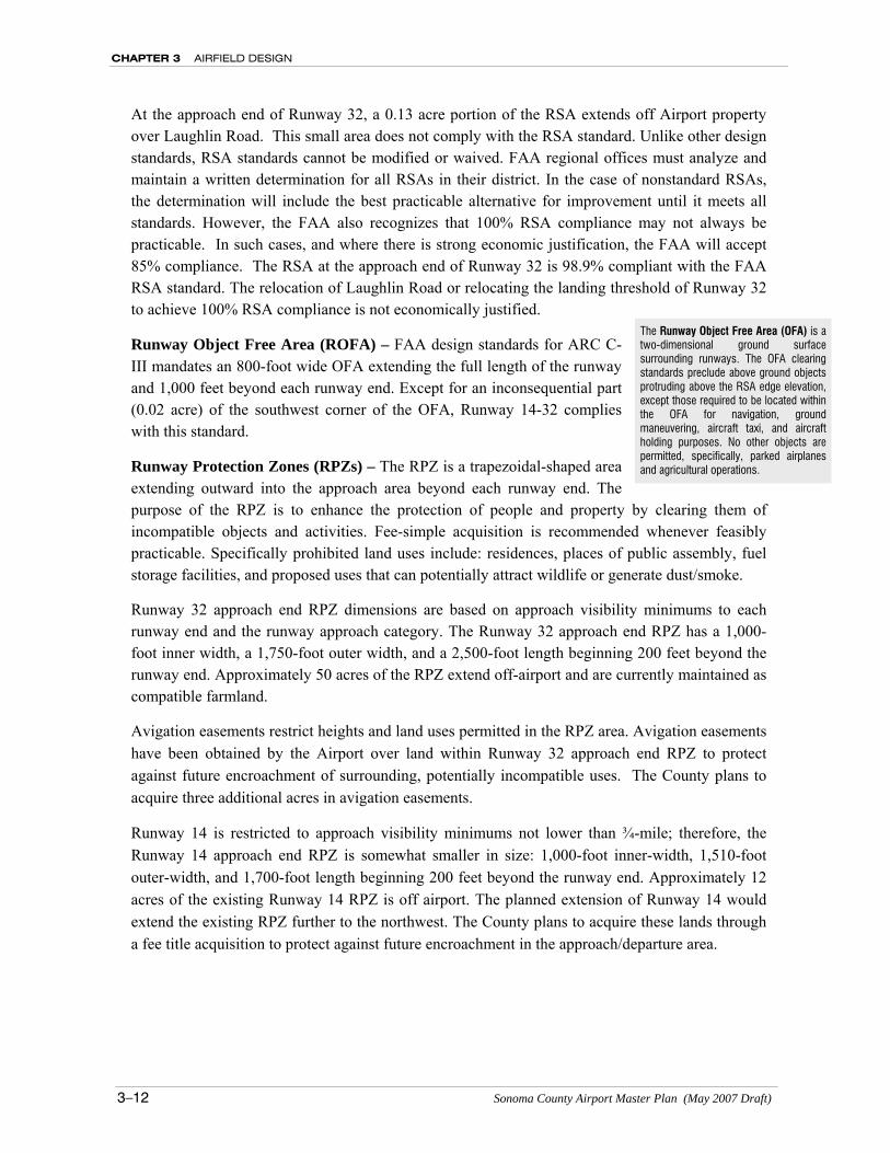
The Runway Object Free Area (OFA) is a two-dimensional ground surface surrounding runways. The OFA clearing standards preclude above ground objects protruding above the RSA edge elevation, except those required to be located within the OFA for navigation, ground maneuvering, aircraft taxi, and aircraft holding purposes. No other objects are permitted, specifically, parked airplanes and agricultural operations.
AIRFIELD DESIGN CHAPTER 3
Sonoma County Airport Master Plan (May 2007 Draft) 3–13
Runway 1-19
Runway 1-19 is constructed of asphalt-concrete. It is designed to accommodate aircraft in ARC C-II (i.e., wingspans less than but up to 79 feet, approach speeds of less than 141 knots), but can accommodate ARC C-III aircraft without any physical changes, but to do so will require some modifications to the runway setback requirements.
The following are major elements associated with Runway 1-19, including: runway length and width, pavement strength, obstacle free zone, runway safety area, runway object free area, and the runway protection zones.
Runway Length and Width – Runway 1-19 is 5,002 feet long by 100 feet wide. These dimensions are generally adequate for the types of operations occurring today. However, to allow air carrier and commuter airline aircraft more flexibility in takeoff procedures the Charles M. Schulz-Sonoma County Airport: Airport Layout Plan Narrative Report and Technical Study recommended extending Runway 1-19 to 5,500-feet (with a 700-foot displaced landing threshold on the north end.4
Pavement Strength – Like the primary runway, the pavement sections are currently rated at: 60,000 pounds single-wheel landing gear, 95,000 pounds dual wheel landing gear, and 150,000 pounds dual tandem landing gear. The strength ratings are based on the mix and volume of aircraft currently using the runway. These ratings are adequate for the 20-year period.
Obstacle Free Zone (OFZ) – Since the runway serves aircraft weighing more than 12,500 pounds, the Runway OFZ width is 400 feet (200 feet either side of the runway centerline at an elevation equal to the nearest runway centerline elevation) and extends 200 feet beyond each runway end. Runway 1-19 currently meets these standards for both ARC C-II and C-III.
Runway Safety Area (RSA) – The RSA is a graded area surrounding and upon which the runway surface is constructed and intended to enhance the safety of airplanes in the event of an unintended excursion from the runway’s paved surface. For ARC C-II runways with approach visibility minimums of ¾ statute miles or higher, the standard RSA dimension is 500 feet wide extending 1,000 feet beyond the stop-end of the runway. However, the current width of Runway 1-19 RSA is 400 feet. This 400-foot RSA width for Runway 1-19 is permitted in accordance with FAA Advisory Design Circular 150/5300-13, Change 10 for ARC C-I and C-II runways. For ARC C-III the RSA must be 500-feet wide.
4 See discussion of Alternative A-1 in Appendix C.
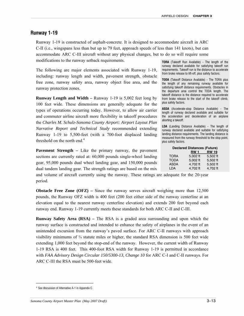
TORA (Takeoff Run Available) - The length of the runway declared available for satisfying takeoff run requirements. Takeoff run is the distance to accelerate from brake release to lift-off, plus safety factors.
TODA (Takeoff Distance Available) - The TORA plus the length of any remaining runway available for satisfying takeoff distance requirements. Obstacles in the departure area control the TODA length. The takeoff distance is the distance required to accelerate from brake release to the start of the takeoff climb, plus safety factors.
ASDA (Accelerate-stop Distance Available) - The length of runway declared available and suitable for the acceleration and deceleration of an airplane aborting a takeoff.
LDA (Landing Distance Available) - The length of runway declared available and suitable for satisfying landing distance requirements. The landing distance is measured from the runway threshold to the stop point, plus safety factors.
Declared Distances (Future) RW 1 RW 19
TORA 5,002 ft 5,502 ft TODA 5,002 ft 5,502 ft ASDA 4,702 ft 5,502 ft LDA 4,702 ft 4,702 ft
CHAPTER 3 AIRFIELD DESIGN
3–14 Sonoma County Airport Master Plan (May 2007 Draft)
Runway 1 currently meets the required distance beyond the stop-end of the runway requirement through the application of Declared Distances. Runway 19 meets the required distance beyond the stop-end of the runway requirement without the need for declared distances.
Runway Object Free Area (ROFA) – FAA design standards for ARC C-II mandates an 800-foot wide OFA extending the full length of the runway and 1,000 feet beyond each runway end. Runway 1-19 complies with this standard.
Runway Protection Zones (RPZs) – Currently, Runway 1-19 RPZs have a 500-foot inner width, 700-foot outer width, and 1,000-foot length beginning 200 feet beyond each runway end. About half of an acre underlies the Runway 19 RPZ that is currently not owned by the Airport, but is agricultural land. Likewise, approximately one- tenth of an acre within the Runway 1 RPZ is off airport. All land outside of Airport property, but within Runway 1-19 RPZs are planned for fee title acquisition. With the upgrading of Runway 1-19 to ARC C-III, the RPZ standard dimensions will increase to 1,700 feet for length, and 1,010 feet wide at the outer end. The 500-foot inner width is unchanged.
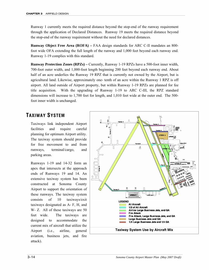
TAXIWAY SYSTEM Taxiways link independent Airport facilities and require careful planning for optimum Airport utility. The taxiway system should provide for free movement to and from runways, terminal/cargo, and parking areas.
Runways 1-19 and 14-32 form an apex that intersects at the approach ends of Runways 19 and 14. An extensive taxiway system has been constructed at Sonoma County Airport to support the orientation of these runways. The taxiway system consists of 10 taxiways/exit taxiways designated as A- F, H, and W- Z. All of these taxiways are 50 feet wide. The taxiways are designed to accommodate the current mix of aircraft that utilize the Airport (i.e., airline, general aviation, business jets, and fire attack).
Taxiway System Use by Aircraft Mix
AIRFIELD DESIGN CHAPTER 3
Sonoma County Airport Master Plan (May 2007 Draft) 3–15
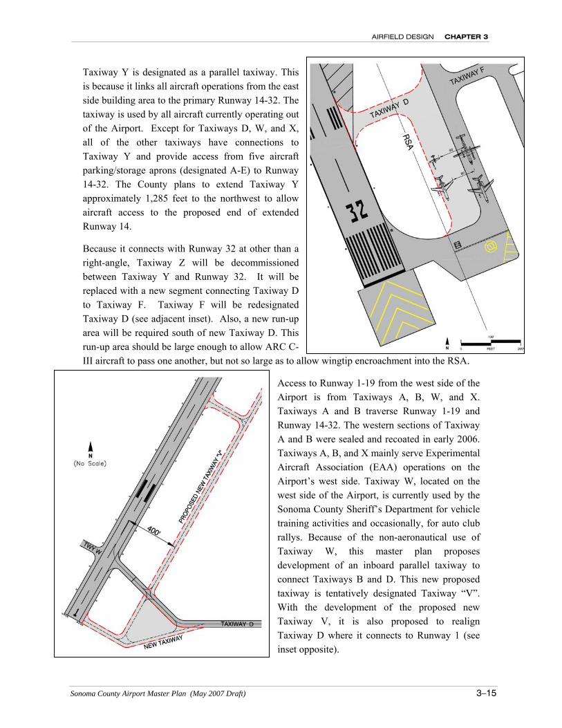
Taxiway Y is designated as a parallel taxiway. This is because it links all aircraft operations from the east side building area to the primary Runway 14-32. The taxiway is used by all aircraft currently operating out of the Airport. Except for Taxiways D, W, and X, all of the other taxiways have connections to Taxiway Y and provide access from five aircraft parking/storage aprons (designated A-E) to Runway 14-32. The County plans to extend Taxiway Y approximately 1,285 feet to the northwest to allow aircraft access to the proposed end of extended Runway 14.
Because it connects with Runway 32 at other than a right-angle, Taxiway Z will be decommissioned between Taxiway Y and Runway 32. It will be replaced with a new segment connecting Taxiway D to Taxiway F. Taxiway F will be redesignated Taxiway D (see adjacent inset). Also, a new run-up area will be required south of new Taxiway D. This run-up area should be large enough to allow ARC C-III aircraft to pass one another, but not so large as to allow wingtip encroachment into the RSA.
Access to Runway 1-19 from the west side of the Airport is from Taxiways A, B, W, and X. Taxiways A and B traverse Runway 1-19 and Runway 14-32. The western sections of Taxiway A and B were sealed and recoated in early 2006. Taxiways A, B, and X mainly serve Experimental Aircraft Association (EAA) operations on the Airport’s west side. Taxiway W, located on the west side of the Airport, is currently used by the Sonoma County Sheriff’s Department for vehicle training activities and occasionally, for auto club rallys. Because of the non-aeronautical use of Taxiway W, this master plan proposes development of an inboard parallel taxiway to connect Taxiways B and D. This new proposed taxiway is tentatively designated Taxiway “V”. With the development of the proposed new Taxiway V, it is also proposed to realign Taxiway D where it connects to Runway 1 (see inset opposite).
CHAPTER 3 AIRFIELD DESIGN
3–16 Sonoma County Airport Master Plan (May 2007 Draft)
On the southern boundary of the Airport, Taxiway D supports Apron F. Taxiway D crosses Runway 1 and Runway 32, providing aircraft access to the west and east sides of the Airport.
Runway Hold Lines
Runway holding position lines (hold lines) identify the location on a taxiway where a pilot is to stop when not cleared to proceed onto the runway. All taxiways intersecting runways must have hold lines located at an appropriate distance from the runway centerline. The appropriate setback distance is determined by the design aircraft and the type of approach to the runway. For angled taxiways, the distance is measured from the edge of the hold line closest to the runway. Except for certain unique situations, the hold lines are to be installed perpendicular to the taxiway centerline. A discussion follows for Runways 14-32 and 1-19.
Runway 14-32 Hold Lines
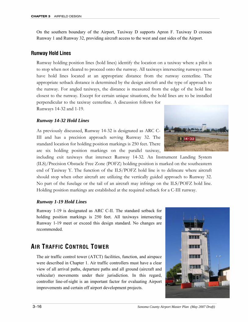
As previously discussed, Runway 14-32 is designated as ARC C-III and has a precision approach serving Runway 32. The standard location for holding position markings is 250 feet. There are six holding position markings on the parallel taxiway, including exit taxiways that intersect Runway 14-32. An Instrument Landing System (ILS)/Precision Obstacle Free Zone (POFZ) holding position is marked on the southeastern end of Taxiway Y. The function of the ILS/POFZ hold line is to delineate where aircraft should stop when other aircraft are utilizing the vertically guided approach to Runway 32. No part of the fuselage or the tail of an aircraft may infringe on the ILS/POFZ hold line. Holding position markings are established at the required setback for a C-III runway.
Runway 1-19 Hold Lines
Runway 1-19 is designated as ARC C-II. The standard setback for holding position markings is 250 feet. All taxiways intersecting Runway 1-19 meet or exceed this design standard. No changes are recommended.
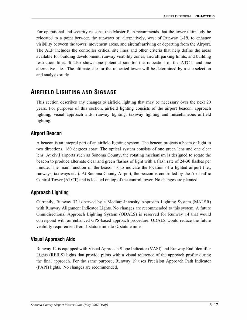
AIR TRAFFIC CONTROL TOWER The air traffic control tower (ATCT) facilities, function, and airspace were described in Chapter 1. Air traffic controllers must have a clear view of all arrival paths, departure paths and all ground (aircraft and vehicular) movements under their jurisdiction. In this regard, controller line-of-sight is an important factor for evaluating Airport improvements and certain off airport development projects.
AIRFIELD DESIGN CHAPTER 3
Sonoma County Airport Master Plan (May 2007 Draft) 3–17
For operational and security reasons, this Master Plan recommends that the tower ultimately be relocated to a point between the runways or, alternatively, west of Runway 1-19, to enhance visibility between the tower, movement areas, and aircraft arriving or departing from the Airport. The ALP includes the controller critical site lines and other criteria that help define the areas available for building development; runway visibility zones, aircraft parking limits, and building restriction lines. It also shows one potential site for the relocation of the ATCT, and one alternative site. The ultimate site for the relocated tower will be determined by a site selection and analysis study.
AIRFIELD LIGHTING AND SIGNAGE This section describes any changes to airfield lighting that may be necessary over the next 20 years. For purposes of this section, airfield lighting consists of the airport beacon, approach lighting, visual approach aids, runway lighting, taxiway lighting and miscellaneous airfield lighting.
Airport Beacon
A beacon is an integral part of an airfield lighting system. The beacon projects a beam of light in two directions, 180 degrees apart. The optical system consists of one green lens and one clear lens. At civil airports such as Sonoma County, the rotating mechanism is designed to rotate the beacon to produce alternate clear and green flashes of light with a flash rate of 24-30 flashes per minute. The main function of the beacon is to indicate the location of a lighted airport (i.e., runways, taxiways etc.). At Sonoma County Airport, the beacon is controlled by the Air Traffic Control Tower (ATCT) and is located on top of the control tower. No changes are planned.
Approach Lighting
Currently, Runway 32 is served by a Medium-Intensity Approach Lighting System (MALSR) with Runway Alignment Indicator Lights. No changes are recommended to this system. A future Omnidirectional Approach Lighting System (ODALS) is reserved for Runway 14 that would correspond with an enhanced GPS-based approach procedure. ODALS would reduce the future visibility requirement from 1 statute mile to ¾-statute miles.
Visual Approach Aids
Runway 14 is equipped with Visual Approach Slope Indicator (VASI) and Runway End Identifier Lights (REILS) lights that provide pilots with a visual reference of the approach profile during the final approach. For the same purpose, Runway 19 uses Precision Approach Path Indicator (PAPI) lights. No changes are recommended.
CHAPTER 3 AIRFIELD DESIGN
3–18 Sonoma County Airport Master Plan (May 2007 Draft)
Runway and Taxiway Lighting
The runway and taxiway edge lighting on Runway 14-32 are adequate. Other than routine maintenance and electrical upgrades, no changes are recommended to the Runway 14-32 lighting system. However, Runway 1-19 is unlighted. Medium Intensity Runway Lights (MIRL) are recommended for Runway 1-19 because this is the back-up runway to Runway 14-32, and because it can be used as an alternative runway for night operations to reduce noise impacts.
Miscellaneous Airfield Lighting
Miscellaneous airfield lights include a variety of airfield elements including: wind indicators, obstruction lights, etc. Three wind cones serve Runway 14-32. All wind cones have obstruction lighting to assist pilots operating at night. Other objects penetrating navigable airspace may also require obstruction lighting in accordance with any airspace evaluations performed for obstacles penetrating Part 77 surfaces.
Airfield Signage
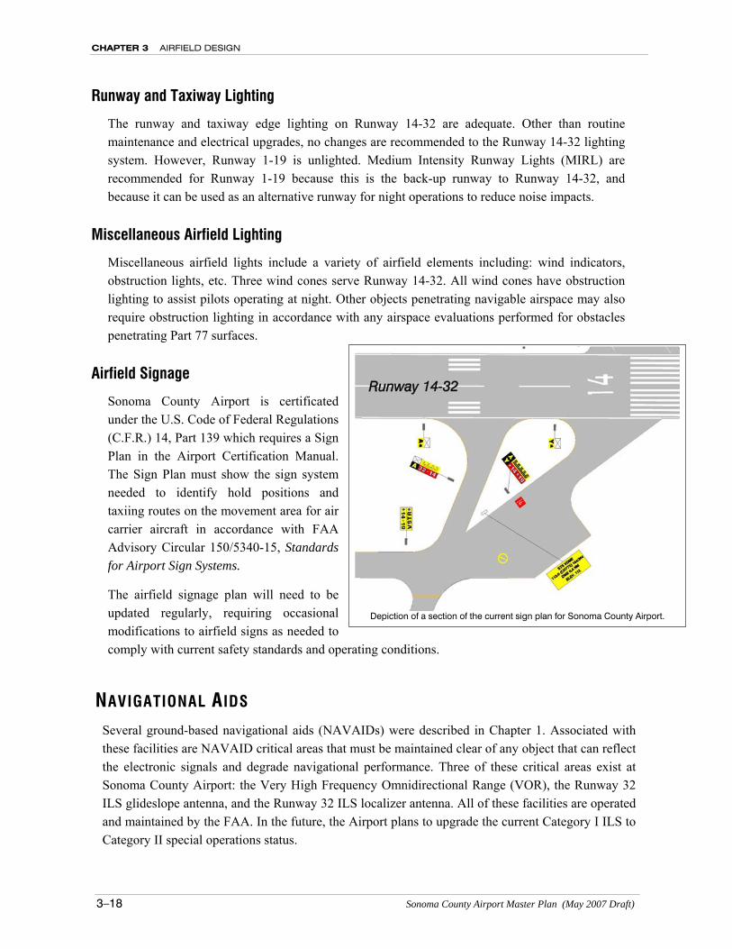
Sonoma County Airport is certificated under the U.S. Code of Federal Regulations (C.F.R.) 14, Part 139 which requires a Sign Plan in the Airport Certification Manual. The Sign Plan must show the sign system needed to identify hold positions and taxiing routes on the movement area for air carrier aircraft in accordance with FAA Advisory Circular 150/5340-15, Standards for Airport Sign Systems.
The airfield signage plan will need to be updated regularly, requiring occasional modifications to airfield signs as needed to comply with current safety standards and operating conditions.
NAVIGATIONAL AIDS Several ground-based navigational aids (NAVAIDs) were described in Chapter 1. Associated with these facilities are NAVAID critical areas that must be maintained clear of any object that can reflect the electronic signals and degrade navigational performance. Three of these critical areas exist at Sonoma County Airport: the Very High Frequency Omnidirectional Range (VOR), the Runway 32 ILS glideslope antenna, and the Runway 32 ILS localizer antenna. All of these facilities are operated and maintained by the FAA. In the future, the Airport plans to upgrade the current Category I ILS to Category II special operations status.
Depiction of a section of the current sign plan for Sonoma County Airport.
AIRFIELD DESIGN CHAPTER 3
Sonoma County Airport Master Plan (May 2007 Draft) 3–19
VOR/DME and Critical Area
A VOR/DME (Santa Rosa – 113.0 MHz/Channel 77) is located on the west side of Runway 14-32. VOR/DME’s radiate azimuth and distance information for enroute navigation and nonprecision instrument approach procedures. The VOR signals are susceptible to distortion caused by reflections. Although a complex mathematical analysis is required to determine the true effect that an object will have on signal reception quality, the FAA has adopted planning guidelines for object setbacks. The VOR/DME at the Airport meets FAA design standards. No changes are recommended.
Runway 32 Localizer Antenna
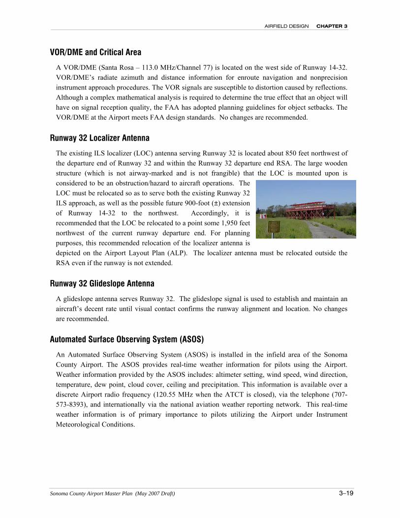
The existing ILS localizer (LOC) antenna serving Runway 32 is located about 850 feet northwest of the departure end of Runway 32 and within the Runway 32 departure end RSA. The large wooden structure (which is not airway-marked and is not frangible) that the LOC is mounted upon is considered to be an obstruction/hazard to aircraft operations. The LOC must be relocated so as to serve both the existing Runway 32 ILS approach, as well as the possible future 900-foot (±) extension of Runway 14-32 to the northwest. Accordingly, it is recommended that the LOC be relocated to a point some 1,950 feet northwest of the current runway departure end. For planning purposes, this recommended relocation of the localizer antenna is depicted on the Airport Layout Plan (ALP). The localizer antenna must be relocated outside the RSA even if the runway is not extended.
Runway 32 Glideslope Antenna
A glideslope antenna serves Runway 32. The glideslope signal is used to establish and maintain an aircraft’s decent rate until visual contact confirms the runway alignment and location. No changes are recommended.
Automated Surface Observing System (ASOS)
An Automated Surface Observing System (ASOS) is installed in the infield area of the Sonoma County Airport. The ASOS provides real-time weather information for pilots using the Airport. Weather information provided by the ASOS includes: altimeter setting, wind speed, wind direction, temperature, dew point, cloud cover, ceiling and precipitation. This information is available over a discrete Airport radio frequency (120.55 MHz when the ATCT is closed), via the telephone (707-573-8393), and internationally via the national aviation weather reporting network. This real-time weather information is of primary importance to pilots utilizing the Airport under Instrument Meteorological Conditions.
CHAPTER 3 AIRFIELD DESIGN
3–20 Sonoma County Airport Master Plan (May 2007 Draft)
OTHER AIRFIELD DESIGN ISSUES This section defines other airfield design setbacks not addressed in other sections, including: runway visibility zones, taxiway object free areas, aircraft parking limit lines, airport imaginary surfaces (C.F.R. 14 Part 77) and building restriction lines. When combined with the setbacks discussed in earlier sections (runway safety areas, runway object free areas, obstacle free zones, and controller line-of-sight, these restrictions establish the areas available for future aviation and non-aviation development discussed in Chapter 5.
Runway Visibility Zones
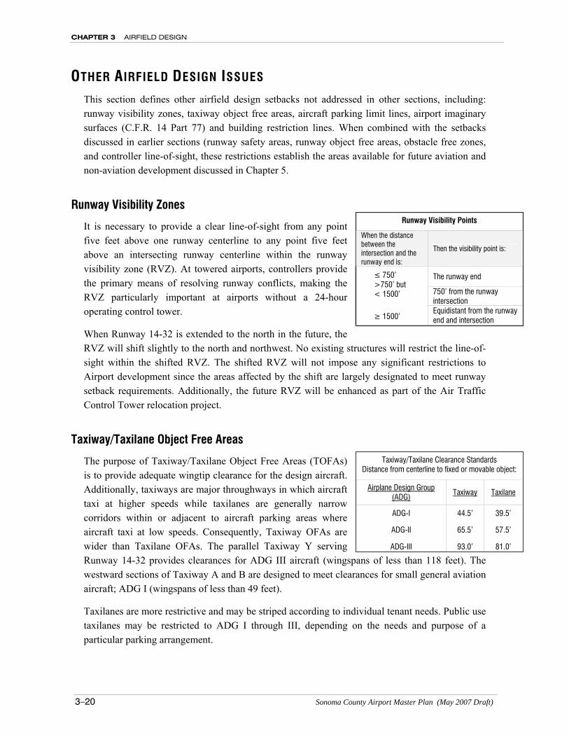
It is necessary to provide a clear line-of-sight from any point five feet above one runway centerline to any point five feet above an intersecting runway centerline within the runway visibility zone (RVZ). At towered airports, controllers provide the primary means of resolving runway conflicts, making the RVZ particularly important at airports without a 24-hour operating control tower.
When Runway 14-32 is extended to the north in the future, the RVZ will shift slightly to the north and northwest. No existing structures will restrict the line-of-sight within the shifted RVZ. The shifted RVZ will not impose any significant restrictions to Airport development since the areas affected by the shift are largely designated to meet runway setback requirements. Additionally, the future RVZ will be enhanced as part of the Air Traffic Control Tower relocation project.
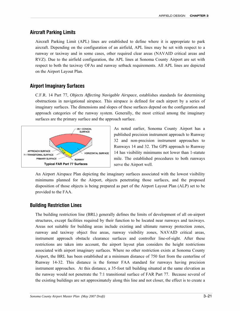
Taxiway/Taxilane Object Free Areas
The purpose of Taxiway/Taxilane Object Free Areas (TOFAs) is to provide adequate wingtip clearance for the design aircraft. Additionally, taxiways are major throughways in which aircraft taxi at higher speeds while taxilanes are generally narrow corridors within or adjacent to aircraft parking areas where aircraft taxi at low speeds. Consequently, Taxiway OFAs are wider than Taxilane OFAs. The parallel Taxiway Y serving Runway 14-32 provides clearances for ADG III aircraft (wingspans of less than 118 feet). The westward sections of Taxiway A and B are designed to meet clearances for small general aviation aircraft; ADG I (wingspans of less than 49 feet).
Taxilanes are more restrictive and may be striped according to individual tenant needs. Public use taxilanes may be restricted to ADG I through III, depending on the needs and purpose of a particular parking arrangement.
Runway Visibility Points
When the distance between the intersection and the runway end is:
Then the visibility point is:
The runway end
750’ from the runway intersection
≤ 750’ >750’ but < 1500’
≥ 1500’ Equidistant from the runway end and intersection
Taxiway/Taxilane Clearance Standards Distance from centerline to fixed or movable object:
Airplane Design Group (ADG) Taxiway Taxilane
ADG-I 44.5’ 39.5’
ADG-II 65.5’ 57.5’
ADG-III 93.0’ 81.0’
AIRFIELD DESIGN CHAPTER 3
Sonoma County Airport Master Plan (May 2007 Draft) 3–21
Aircraft Parking Limits
Aircraft Parking Limit (APL) lines are established to define where it is appropriate to park aircraft. Depending on the configuration of an airfield, APL lines may be set with respect to a runway or taxiway and in some cases, other required clear areas (NAVAID critical areas and RVZ). Due to the airfield configuration, the APL lines at Sonoma County Airport are set with respect to both the taxiway OFAs and runway setback requirements. All APL lines are depicted on the Airport Layout Plan.
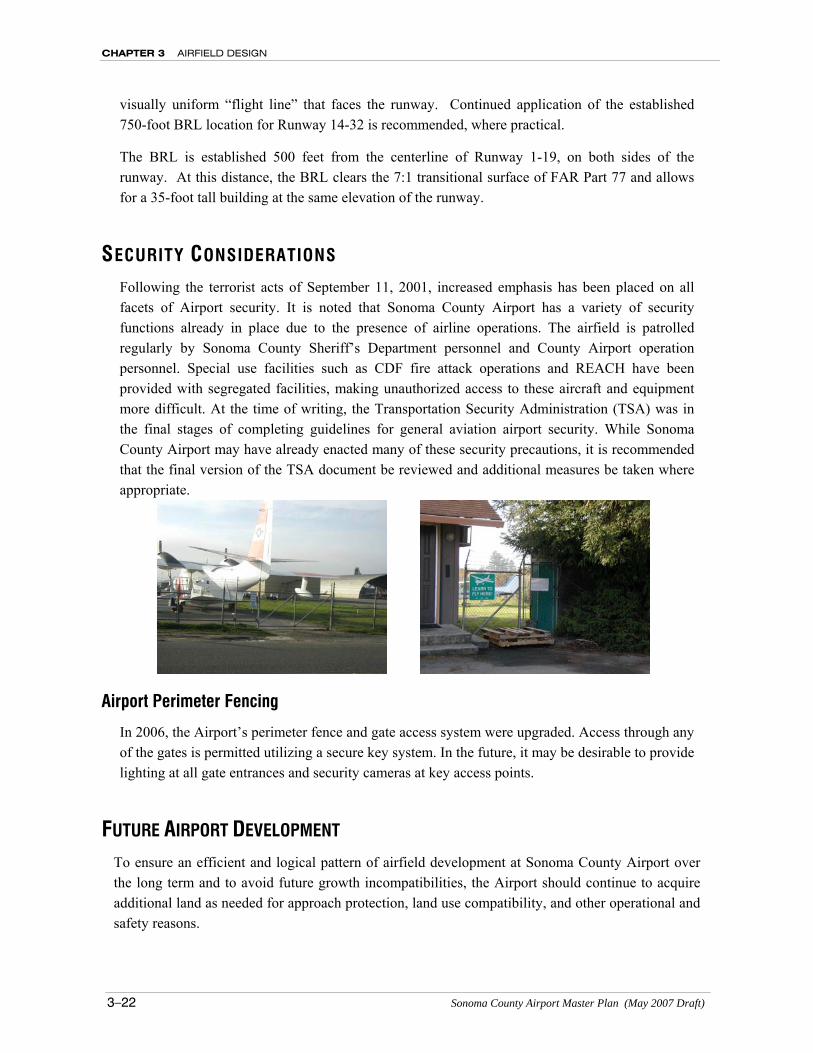
Airport Imaginary Surfaces
C.F.R. 14 Part 77, Objects Affecting Navigable Airspace, establishes standards for determining obstructions in navigational airspace. This airspace is defined for each airport by a series of imaginary surfaces. The dimensions and slopes of these surfaces depend on the configuration and approach categories of the runway system. Generally, the most critical among the imaginary surfaces are the primary surface and the approach surface.
As noted earlier, Sonoma County Airport has a published precision instrument approach to Runway 32 and non-precision instrument approaches to Runways 14 and 32. The GPS approach to Runway 14 has visibility minimums not lower than 1-statute mile. The established procedures to both runways serve the Airport well.
An Airport Airspace Plan depicting the imaginary surfaces associated with the lowest visibility minimums planned for the Airport, objects penetrating those surfaces, and the proposed disposition of those objects is being prepared as part of the Airport Layout Plan (ALP) set to be provided to the FAA.
Building Restriction Lines
The building restriction line (BRL) generally defines the limits of development of all on-airport structures, except facilities required by their function to be located near runways and taxiways. Areas not suitable for building areas include existing and ultimate runway protection zones, runway and taxiway object free areas, runway visibility zones, NAVAID critical areas, instrument approach obstacle clearance surfaces and controller line-of-sight. After these restrictions are taken into account, the airport layout plan considers the height restrictions associated with airport imaginary surfaces. Where no other restriction exists at Sonoma County Airport, the BRL has been established at a minimum distance of 750 feet from the centerline of Runway 14-32. This distance is the former FAA standard for runways having precision instrument approaches. At this distance, a 35-foot tall building situated at the same elevation as the runway would not penetrate the 7:1 transitional surface of FAR Part 77. Because several of the existing buildings are set approximately along this line and not closer, the effect is to create a
Typical FAR Part 77 Surfaces
CHAPTER 3 AIRFIELD DESIGN
3–22 Sonoma County Airport Master Plan (May 2007 Draft)
visually uniform “flight line” that faces the runway. Continued application of the established 750-foot BRL location for Runway 14-32 is recommended, where practical.
The BRL is established 500 feet from the centerline of Runway 1-19, on both sides of the runway. At this distance, the BRL clears the 7:1 transitional surface of FAR Part 77 and allows for a 35-foot tall building at the same elevation of the runway.
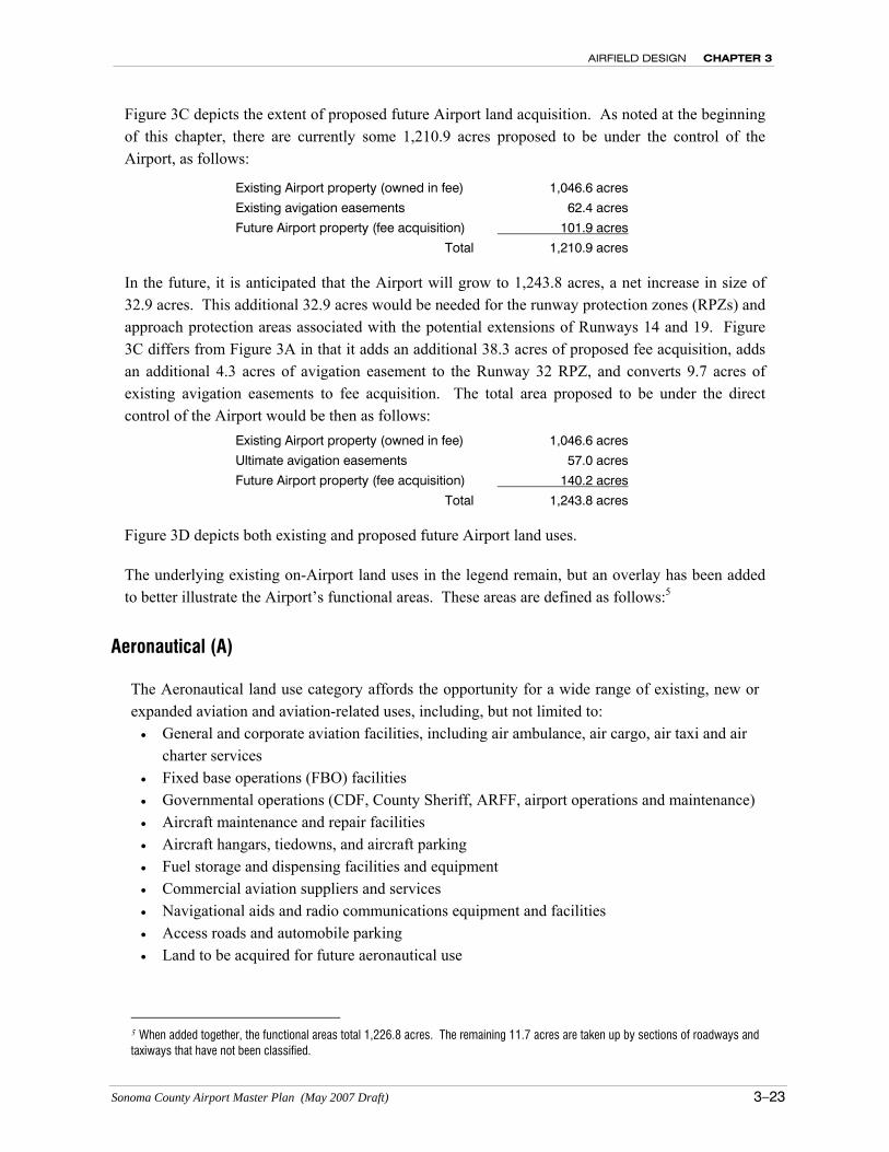
SECURITY CONSIDERATIONS Following the terrorist acts of September 11, 2001, increased emphasis has been placed on all facets of Airport security. It is noted that Sonoma County Airport has a variety of security functions already in place due to the presence of airline operations. The airfield is patrolled regularly by Sonoma County Sheriff’s Department personnel and County Airport operation personnel. Special use facilities such as CDF fire attack operations and REACH have been provided with segregated facilities, making unauthorized access to these aircraft and equipment more difficult. At the time of writing, the Transportation Security Administration (TSA) was in the final stages of completing guidelines for general aviation airport security. While Sonoma County Airport may have already enacted many of these security precautions, it is recommended that the final version of the TSA document be reviewed and additional measures be taken where appropriate.
Airport Perimeter Fencing
In 2006, the Airport’s perimeter fence and gate access system were upgraded. Access through any of the gates is permitted utilizing a secure key system. In the future, it may be desirable to provide lighting at all gate entrances and security cameras at key access points.
FUTURE AIRPORT DEVELOPMENT To ensure an efficient and logical pattern of airfield development at Sonoma County Airport over the long term and to avoid future growth incompatibilities, the Airport should continue to acquire additional land as needed for approach protection, land use compatibility, and other operational and safety reasons.
AIRFIELD DESIGN CHAPTER 3
Sonoma County Airport Master Plan (May 2007 Draft) 3–23
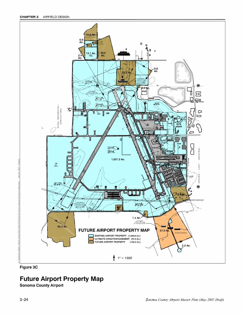
Figure 3C depicts the extent of proposed future Airport land acquisition. As noted at the beginning of this chapter, there are currently some 1,210.9 acres proposed to be under the control of the Airport, as follows:
Existing Airport property (owned in fee) 1,046.6 acres
Existing avigation easements 62.4 acres
Future Airport property (fee acquisition) 101.9 acres
Total 1,210.9 acres
In the future, it is anticipated that the Airport will grow to 1,243.8 acres, a net increase in size of 32.9 acres. This additional 32.9 acres would be needed for the runway protection zones (RPZs) and approach protection areas associated with the potential extensions of Runways 14 and 19. Figure 3C differs from Figure 3A in that it adds an additional 38.3 acres of proposed fee acquisition, adds an additional 4.3 acres of avigation easement to the Runway 32 RPZ, and converts 9.7 acres of existing avigation easements to fee acquisition. The total area proposed to be under the direct control of the Airport would be then as follows:
Existing Airport property (owned in fee) 1,046.6 acres
Ultimate avigation easements 57.0 acres
Future Airport property (fee acquisition) 140.2 acres
Total 1,243.8 acres
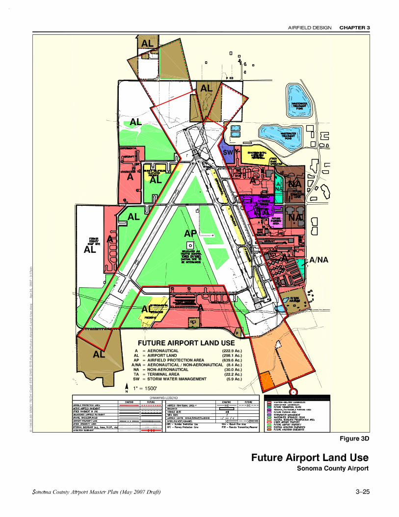
Figure 3D depicts both existing and proposed future Airport land uses.
The underlying existing on-Airport land uses in the legend remain, but an overlay has been added to better illustrate the Airport’s functional areas. These areas are defined as follows:5
Aeronautical (A)
The Aeronautical land use category affords the opportunity for a wide range of existing, new or expanded aviation and aviation-related uses, including, but not limited to: • General and corporate aviation facilities, including air ambulance, air cargo, air taxi and air
charter services • Fixed base operations (FBO) facilities • Governmental operations (CDF, County Sheriff, ARFF, airport operations and maintenance) • Aircraft maintenance and repair facilities • Aircraft hangars, tiedowns, and aircraft parking • Fuel storage and dispensing facilities and equipment • Commercial aviation suppliers and services • Navigational aids and radio communications equipment and facilities • Access roads and automobile parking • Land to be acquired for future aeronautical use
5 When added together, the functional areas total 1,226.8 acres. The remaining 11.7 acres are taken up by sections of roadways and taxiways that have not been classified.
CHAPTER 3 AIRFIELD DESIGN
3–26 Sonoma County Airport Master Plan (May 2007 Draft)
Aeronautical/Non-Aeronautical (A/NA)
This category of use is designed to provide flexibility for future development. Depending on demand or other market factors the areas designated A/NA may be developed for either aeronautical or non-aeronautical purposes. For aeronautical uses, see the definition of Aeronautical above. For non-aeronautical use see the following definition for Non-Aeronautical.
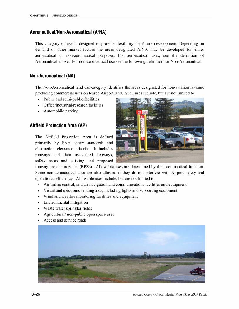
Non-Aeronautical (NA)
The Non-Aeronautical land use category identifies the areas designated for non-aviation revenue producing commercial uses on leased Airport land. Such uses include, but are not limited to: • Public and semi-public facilities • Office/industrial/research facilities • Automobile parking
Airfield Protection Area (AP)
The Airfield Protection Area is defined primarily by FAA safety standards and obstruction clearance criteria. It includes runways and their associated taxiways, safety areas and existing and proposed runway protection zones (RPZs). Allowable uses are determined by their aeronautical function. Some non-aeronautical uses are also allowed if they do not interfere with Airport safety and operational efficiency. Allowable uses include, but are not limited to: • Air traffic control, and air navigation and communications facilities and equipment • Visual and electronic landing aids, including lights and supporting equipment • Wind and weather monitoring facilities and equipment • Environmental mitigation • Waste water sprinkler fields • Agricultural/ non-public open space uses • Access and service roads
AIRFIELD DESIGN CHAPTER 3
Sonoma County Airport Master Plan (May 2007 Draft) 3–27
Airport Land (AL)
Areas included within the Airport property boundaries that are not designated for any specific development, but which may support a variety of individual or combined uses, including, but are not limited to: • Approach protection • Safety buffer zones • Navigational aids and radio communications equipment and facilities • Environmental mitigation • Waste water sprinkler fields • Agricultural/non-public open space uses
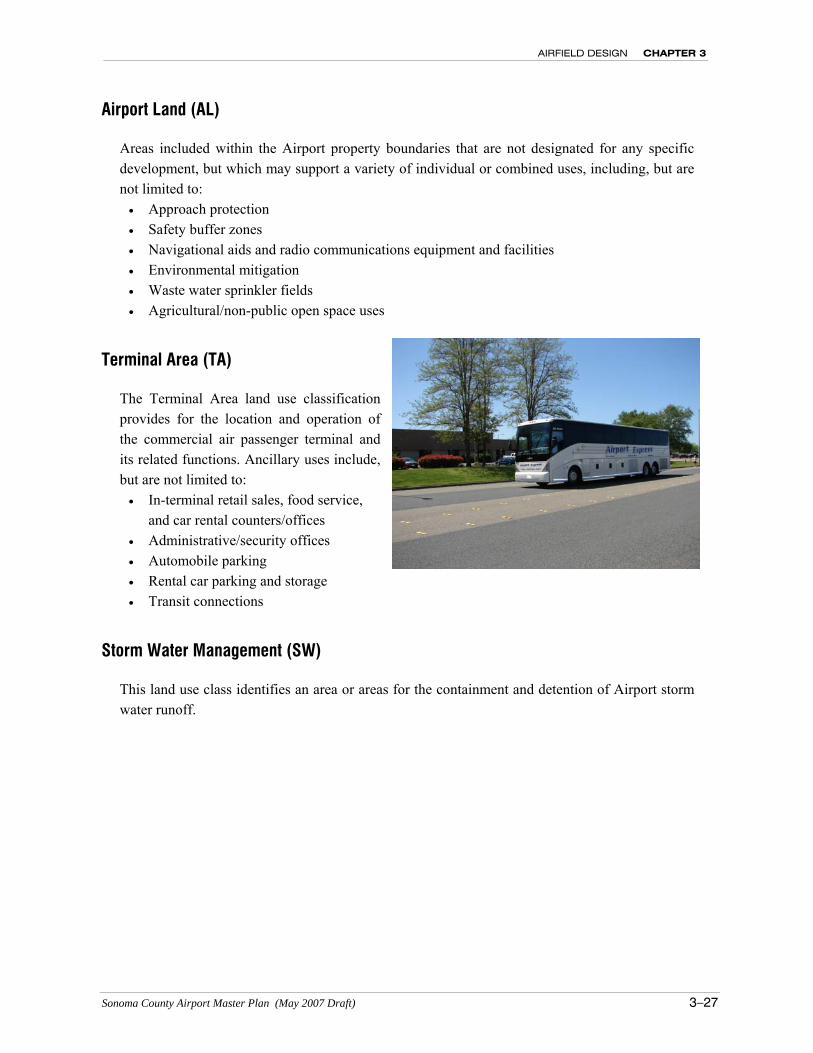
Terminal Area (TA)
The Terminal Area land use classification provides for the location and operation of the commercial air passenger terminal and its related functions. Ancillary uses include, but are not limited to: • In-terminal retail sales, food service,
and car rental counters/offices • Administrative/security offices • Automobile parking • Rental car parking and storage • Transit connections
Storm Water Management (SW)
This land use class identifies an area or areas for the containment and detention of Airport storm water runoff.