Embed Size (px)
Citation preview

MAY 2009 CONTENTS i
CONTENTS
Section Page
STS-125 MISSION OVERVIEW .. . . . . . . . . . . . . . . . . . . . . . . . . . . . . . . . . . . . . . . . . . . . . . . . . . . . . . . . . . . . . . . . . . . . . . . . . . . . . . . . . . . . . . . . . . . . . . . 1
SPACE SHUTTLE ENDEAVOUR (STS-400) TO THE RESCUE – IF REQUIRED . . . . . . . . . . . . . . . . . . . . . . . . . . . 11
STS-125 TIMELINE OVERVIEW .. . . . . . . . . . . . . . . . . . . . . . . . . . . . . . . . . . . . . . . . . . . . . . . . . . . . . . . . . . . . . . . . . . . . . . . . . . . . . . . . . . . . . . . . . . . . . . 17
MISSION PROFILE. . . . . . . . . . . . . . . . . . . . . . . . . . . . . . . . . . . . . . . . . . . . . . . . . . . . . . . . . . . . . . . . . . . . . . . . . . . . . . . . . . . . . . . . . . . . . . . . . . . . . . . . . . . . . . . .. . . 19
HST SERVICING MISSION PRIORITIES . . . . . . . . . . . . . . . . . . . . . . . . . . . . . . . . . . . . . . . . . . . . . . . . . . . . . . . . . . . . . . . . . . . . . . . . . . . . . . . . . . 21
HUBBLE SPACE TELESCOPE HISTORY . . . . . . . . . . . . . . . . . . . . . . . . . . . . . . . . . . . . . . . . . . . . . . . . . . . . . . . . . . . . . . . . . . . . . . . . . . . . . . . . . . . . 23
FLIGHT CONTROL . . . . . . . . . . . . . . . . . . . . . . . . . . . . . . . . . . . . . . . . . . . . . . . . . . . . . . . . . . . . . . . . . . . . . . . . . . . . . . . . . . . . . . . . . . . . . . . . . . . . . . . . . . . . . . . . .. . . 33
STS-125 ATLANTIS CREW .. . . . . . . . . . . . . . . . . . . . . . . . . . . . . . . . . . . . . . . . . . . . . . . . . . . . . . . . . . . . . . . . . . . . . . . . . . . . . . . . . . . . . . . . . . . . . . . . . . . . . 35
PAYLOAD OVERVIEW .. . . . . . . . . . . . . . . . . . . . . . . . . . . . . . . . . . . . . . . . . . . . . . . . . . . . . . . . . . . . . . . . . . . . . . . . . . . . . . . . . . . . . . . . . . . . . . . . . . . . . . . . . . . . .
H U B B L E S E R V I C I N G M I S S I O N P A Y L O A D B A Y H A R D W A R E . . . . . . . . . . . . . . . . . . . . . . . . . . . . . . . . . . . . . . . . . . . . . . . . . . . . . . . . . . . . . . . . . . .
F L I G H T S U P P O R T S Y S T E M ( F S S ) . . . . . . . . . . . . . . . . . . . . . . . . . . . . . . . . . . . . . . . . . . . . . . . . . . . . . . . . . . . . . . . . . . . . . . . . . . . . . . . . . . . . . . . . . . . . . . . . . . . . . . . . .
S O F T C A P T U R E A N D R E N D E Z V O U S S Y S T E M ( S C R S ) . . . . . . . . . . . . . . . . . . . . . . . . . . . . . . . . . . . . . . . . . . . . . . . . . . . . . . . . . . . . . . . . . . . . . . . . . . . .
S U P E R L I G H T W E I G H T I N T E R C H A N G E A B L E C A R R I E R ( S L I C ) . . . . . . . . . . . . . . . . . . . . . . . . . . . . . . . . . . . . . . . . . . . . . . . . . . . . . . . . . . . . . . . .
O R B I T A L R E P L A C E M E N T U N I T C A R R I E R . . . . . . . . . . . . . . . . . . . . . . . . . . . . . . . . . . . . . . . . . . . . . . . . . . . . . . . . . . . . . . . . . . . . . . . . . . . . . . . . . . . . . . . . . . . . . .
M U L T I - U S E L I G H T W E I G H T E Q U I P M E N T C A R R I E R . . . . . . . . . . . . . . . . . . . . . . . . . . . . . . . . . . . . . . . . . . . . . . . . . . . . . . . . . . . . . . . . . . . . . . . . . . . . . . . .
45 4 5
4 5 4 5 4 7
4 8 4 9
RENDEZVOUS & DOCKING. . . . . . . . . . . . . . . . . . . . . . . . . . . . . . . . . . . . . . . . . . . . . . . . . . . . . . . . . . . . . . . . . . . . . . . . . . . . . . . . . . . . . . . . . . . . . . . . . . . . . . . 69
SPACEWALKS . . . . . . . . . . . . . . . . . . . . . . . . . . . . . . . . . . . . . . . . . . . . . . . . . . . . . . . . . . . . . . . . . . . . . . . . . . . . . . . . . . . . . . . . . . . . . . . . . . . . . . . . . . . . . . . . . . . . .. . . . 73
SM4 FACILITIES . . . . . . . . . . . . . . . . . . . . . . . . . . . . . . . . . . . . . . . . . . . . . . . . . . . . . . . . . . . . . . . . . . . . . . . . . . . . . . . . . . . . . . . . . . . . . . . . . . . . . . . . . . . . . . . . .. . . . 83
SHUTTLE REFERENCE DATA . . . . . . . . . . . . . . . . . . . . . . . . . . . . . . . . . . . . . . . . . . . . . . . . . . . . . . . . . . . . . . . . . . . . . . . . . . . . . . . . . . . . . . . . . . . . . . . . . . . . 87
Section Page
ii CONTENTS MAY 2009
LAUNCH AND LANDING . . . . . . . . . . . . . . . . . . . . . . . . . . . . . . . . . . . . . . . . . . . . . . . . . . . . . . . . . . . . . . . . . . . . . . . . . . . . . . . . . . . . . . . . . . . . . . . . . . . . . . . . . . . 105 L A U N C H . . . . . . . . . . . . . . . . . . . . . . . . . . . . . . . . . . . . . . . . . . . . . . . . . . . . . . . . . . . . . . . . . . . . . . . . . . . . . . . . . . . . . . . . . . . . . . . . . . . . . . . . . . . . . . . . . . . . . . . . .. . . . . . . . . . . . . . . . . . . . . . 1 0 5 A B O R T - T O - O R B I T . . . . . . . . . . . . . . . . . . . . . . . . . . . . . . . . . . . . . . . . . . . . . . . . . . . . . . . . . . . . . . . . . . . . . . . . . . . . . . . . . . . . . . . . . . . . . . . . . . . . . . . . . . . . . . . . . . . . . . . . . . . . . . . . 1 0 5 T R A N S A T L A N T I C A B O R T L A N D I N G . . . . . . . . . . . . . . . . . . . . . . . . . . . . . . . . . . . . . . . . . . . . . . . . . . . . . . . . . . . . . . . . . . . . . . . . . . . . . . . . . . . . . . . . . . . . . . . . . . . . . . 1 0 5 R E T U R N - T O - L A U N C H - S I T E . . . . . . . . . . . . . . . . . . . . . . . . . . . . . . . . . . . . . . . . . . . . . . . . . . . . . . . . . . . . . . . . . . . . . . . . . . . . . . . . . . . . . . . . . . . . . . . . . . . . . . . . . . . . . . . . . . . 1 0 5 A B O R T O N C E A R O U N D . . . . . . . . . . . . . . . . . . . . . . . . . . . . . . . . . . . . . . . . . . . . . . . . . . . . . . . . . . . . . . . . . . . . . . . . . . . . . . . . . . . . . . . . . . . . . . . . . . . . . . . . . . . . . .. . . . . . . . . . . 1 0 5 L A N D I N G . . . . . . . . . . . . . . . . . . . . . . . . . . . . . . . . . . . . . . . . . . . . . . . . . . . . . . . . . . . . . . . . . . . . . . . . . . . . . . . . . . . . . . . . . . . . . . . . . . . . . . . . . . . . . . . . . . . . . . . .. . . . . . . . . . . . . . . . . . . . . 1 0 5
MEDIA ASSISTANCE . . . . . . . . . . . . . . . . . . . . . . . . . . . . . . . . . . . . . . . . . . . . . . . . . . . . . . . . . . . . . . . . . . . . . . . . . . . . . . . . . . . . . . . . . . . . . . . . . . . . . . . . . . . . . . . 113
PUBLIC AFFAIRS CONTACTS . . . . . . . . . . . . . . . . . . . . . . . . . . . . . . . . . . . . . . . . . . . . . . . . . . . . . . . . . . . . . . . . . . . . . . . . . . . . . . . . . . . . . . . . . . . . . . . . . . 115

MAY 2009 MISSION OVERVIEW 1
STS-125 MISSION OVERVIEW
From the left are astronauts Mike Massimino, Michael Good, both mission specialists;
Gregory C. Johnson, pilot; Scott Altman, commander; Megan McArthur, John Grunsfeld and Andrew Feustel, all mission specialists.
The STS‐125 mission of space shuttle Atlantis is scheduled for launch at 2:01 p.m. EDT on Monday, May 11, from Launch Complex 39A at NASA’s Kennedy Space Center, Fla. Atlantis’ crew will service the Hubble Space Telescope for the fifth and final time.
Nineteen years since its launch in April 1990, Hubble’s view of the universe again will be dramatically improved with the addition of two new science instruments, the repair of two others, and the replacement of other hardware
that will extend the telescope’s life into the next decade.
The mission will be commanded by retired Navy Capt. Scott Altman with retired Navy Capt. Gregory C. Johnson serving as pilot. Megan McArthur is the flight engineer. The remaining four mission specialists will pair off in teams for the five spacewalks. They are Andrew Feustel, Air Force Col. Michael Good, John Grunsfeld, and Mike Massimino.

2 MISSION OVERVIEW MAY 2009
This graphic depicts the location of the STS‐125 payload hardware.
Altman will make his fourth flight, Grunsfeld his fifth and Massimino his second. Their last mission was together on the fourth Hubble servicing mission, STS‐109, in March 2002. The other four crew members are rookies. Grunsfeld will make his third consecutive visit to Hubble, having performed five spacewalks on his previous missions.
On STS‐125, Grunsfeld and Feustel will team on the odd‐numbered spacewalks, while Massimino and Good are paired on spacewalks two and four.
Identifying the Spacewalkers:
John Grunsfeld – Solid red stripes Drew Feustel – No markings (solid white suit) Mike Massimino – Broken horizontal red stripes Michael Good – Diagonal red stripes (barber pole)
After launch, the crew will oversee the checkout of the robotic arm, which will see extensive action throughout the mission to position spacewalkers in close proximity to worksites. The arm also will be used to survey the outside surfaces of Atlantis’ crew cabin.
Additionally, the robotic arm will be used on the second day of the flight to inspect the shuttle’s sensitive thermal protection system using the Orbiter Boom Sensor System. The boom includes sensors that can detect any significant damage that may have occurred during the launch and climb to orbit. Imagery experts in Mission Control, Houston, will evaluate that data in near real‐time, to determine the health of the orbiter’s thermal protection system. The boom is tucked along the right sill of the payload bay, which also houses the rest of the mission’s science instruments, protective canisters and hardware.

MAY 2009 MISSION OVERVIEW 3
Astronaut John Grunsfeld, STS‐125 mission specialist, dons a training version of the Extravehicular Mobility Unit (EMU) spacesuit before being submerged in the waters of the Neutral Buoyancy Laboratory (NBL) near the Johnson Space Center. Astronauts
Gregory C. Johnson (left) and Mike Massimino assist Grunsfeld.
On Flight Day Three Atlantis will arrive within 35 feet of the telescope, at an altitude of about 350 statute miles. McArthur will carefully extend the robotic arm to capture a grapple fixture on the telescope. She then will carefully place Hubble atop its Flight Support System, or FSS, in the back end of the shuttle’s payload bay.
The FSS serves as a high‐tech “lazy Susan” that can be rotated and tilted to present the desired part of the telescope forward for easy access by spacewalkers, and to offer the best viewing angles for cameras and crew members inside Atlantis. It also provides all electrical and mechanical interfaces between the shuttle and the telescope.
With Atlantis’ payload bay essentially serving as a giant tool box, the stage is set for the first of five spacewalks, known as Extravehicular Activity, or EVA, on consecutive days beginning on Flight Day Four. Each spacewalk is scheduled to last about 6 1/2 hours.
Since almost every part of Hubble was designed to be repaired and upgraded by astronauts, training has focused on actual hardware at NASA’s Goddard Space Flight Center, Greenbelt, Md., and underwater mockups at the Johnson Space Center in Houston, where timelines have been refined for each day’s scheduled work.

4 MISSION OVERVIEW MAY 2009
The actual servicing of Hubble will begin on Flight Day Four with the first EVA. Grunsfeld, joined by Feustel initially, will focus on swapping the current Wide Field Planetary Camera 2 with the like-sized Wide Field Camera 3, which will extend Hubble’s capability not only by seeing deeper into the universe, but also by providing wide-field imagery in all three regions of the spectrum – ultraviolet, visible and near infrared. It is this wide-field “panchromatic” coverage that makes WFC3 so unique. The new instrument has a mass of 900 pounds and measures 26 inches high, 74 inches wide, and 87 inches long.
The next task has Grunsfeld and Feustel swapping the Science Instrument Command and Data Handling (SI C&DH) system in Bay 10 with a ground spare called into service when the in-orbit unit’s “A” side suffered a permanent electronic failure in late September 2008. The unit provides command capability to Hubble’s science instruments from the ground and sends data back. Its criticality dictated a slight shuffle to the spacewalk plan to place the removal and replacement of the SI C&DH as the servicing mission’s second major task.
The first spacewalk will wrap up with a forward-looking task requiring installation of a Soft Capture and Rendezvous System, or SCRS, which will enable the future rendezvous, capture, and safe disposal of Hubble by either a crewed or robotic mission.
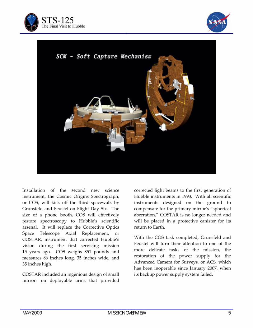
Comprised of the Soft Capture Mechanism, or SCM, and the Relative Navigation System, or
RNS, the SCRS will mount underneath the telescope, using a Low Impact Docking System, or LIDS, interface. LIDS is designed to be compatible with the rendezvous and docking systems that will be used on the next-generation space transportation vehicle.
The SCM is about 72 inches in diameter and 24 inches high and will be attached to the telescope by three sets of jaws that clamp onto the existing berthing pins on Hubble’s aft bulkhead.
Alternating EVA days, Massimino and Good will take their turn on Flight Day Five, focusing on the removal and replacement of three pairs of gyroscopes known as Rate Sensor Units, or RSUs. In concert with star trackers and Fine Guidance Sensors (FGS), the RSUs help point the telescope precisely for its science observations.
EVA 2 will end with the swap out of the first of two battery modules behind an equipment bay directly above the WFC3 location. Each module weighs 460 pounds and measures 36 inches long, 32 inches wide, and 11 inches high and contains three batteries. Each nickel hydrogen battery weighs 125 pounds and provides all the electrical power to support Hubble operations during the night portion of its orbit. The second battery module will be installed during the fifth and final EVA.
Designed to last only five years, Hubble’s batteries have lasted more than 13 years beyond their design life, longer than those in any other spacecraft located in low Earth orbit.
MAY 2009 MISSION OVERVIEW 5
Installation of the second new science instrument, the Cosmic Origins Spectrograph, or COS, will kick off the third spacewalk by Grunsfeld and Feustel on Flight Day Six. The size of a phone booth, COS will effectively restore spectroscopy to Hubble’s scientific arsenal. It will replace the Corrective Optics Space Telescope Axial Replacement, or COSTAR, instrument that corrected Hubble’s vision during the first servicing mission 15 years ago. COS weighs 851 pounds and measures 86 inches long, 35 inches wide, and 35 inches high.
COSTAR included an ingenious design of small mirrors on deployable arms that provided
corrected light beams to the first generation of Hubble instruments in 1993. With all scientific instruments designed on the ground to compensate for the primary mirror’s “spherical aberration,” COSTAR is no longer needed and will be placed in a protective canister for its return to Earth.
With the COS task completed, Grunsfeld and Feustel will turn their attention to one of the more delicate tasks of the mission, the restoration of the power supply for the Advanced Camera for Surveys, or ACS, which has been inoperable since January 2007, when its backup power supply system failed.

6 MISSION OVERVIEW MAY 2009
While seated at the commander’s station, astronaut Scott Altman, STS-125 commander, participates in a post insertion/de-orbit training session in the crew compartment trainer (CCT-2)
in the Space Vehicle Mockup Facility at Johnson Space Center.
Repairing the ACS power supply will begin by preparing the worksite for removal and replacement of the failed circuit boards. This requires first removing 36 screws from the electronics access panel using a specially designed “fastener capture plate” that will prevent loss of the tiny screws after removal. When all of the screws have been removed, the entire capture plate can be released as one unit, safely taking the access panel and screws with it.
With the ACS power failure likely confined to the instrument’s low-voltage power supply, a direct repair of that subsystem would require too much time for the spacewalk, so engineers devised a plan to replace the entire electronics
box, which will be powered by a separate low-voltage power supply. The replacement power supply draws power from the Advanced Camera for Surveys’ primary power connectors via an astronaut-installed splitter cable.
If careful removal of 36 screws weren’t enough, the fourth spacewalk on Flight Day Seven will arguably set the bar higher for access panel removal when Massimino and Good focus on the repair of the Space Telescope Imaging Spectrograph’s, or STIS, power supply system. They will begin by attaching another fastener capture plate to secure 117 screws, so they will not have to capture them with their pressurized gloved hands.
MAY 2009 MISSION OVERVIEW 7
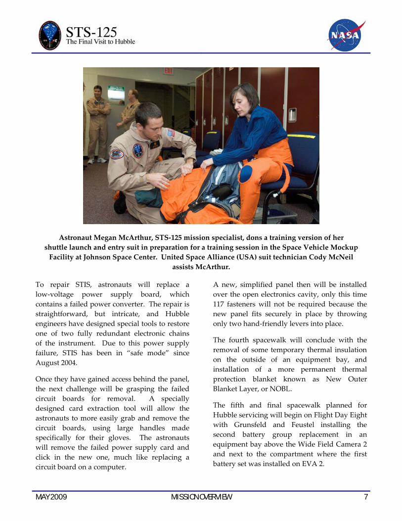
Astronaut Megan McArthur, STS-125 mission specialist, dons a training version of her shuttle launch and entry suit in preparation for a training session in the Space Vehicle Mockup
Facility at Johnson Space Center. United Space Alliance (USA) suit technician Cody McNeil assists McArthur.
To repair STIS, astronauts will replace a low-voltage power supply board, which contains a failed power converter. The repair is straightforward, but intricate, and Hubble engineers have designed special tools to restore one of two fully redundant electronic chains of the instrument. Due to this power supply failure, STIS has been in “safe mode” since August 2004.
Once they have gained access behind the panel, the next challenge will be grasping the failed circuit boards for removal. A specially designed card extraction tool will allow the astronauts to more easily grab and remove the circuit boards, using large handles made specifically for their gloves. The astronauts will remove the failed power supply card and click in the new one, much like replacing a circuit board on a computer.
A new, simplified panel then will be installed over the open electronics cavity, only this time 117 fasteners will not be required because the new panel fits securely in place by throwing only two hand-friendly levers into place.
The fourth spacewalk will conclude with the removal of some temporary thermal insulation on the outside of an equipment bay, and installation of a more permanent thermal protection blanket known as New Outer Blanket Layer, or NOBL.
The fifth and final spacewalk planned for Hubble servicing will begin on Flight Day Eight with Grunsfeld and Feustel installing the second battery group replacement in an equipment bay above the Wide Field Camera 2 and next to the compartment where the first battery set was installed on EVA 2.

8 MISSION OVERVIEW MAY 2009
This image depicts the release of the Hubble Space Telescope on Flight Day 9.
The two astronauts then will remove and replace one of the three Fine Guidance Sensors, FGS-2, used to provide pointing information for the spacecraft. The sensors also serve as a scientific instrument for determining the precise position and motion of stars, known as astrometry.
The three Fine Guidance Sensors can hold the telescope steady for scientific observations over long periods of time. The system serves as the telescope’s pointing control system and has a precision comparable to being able to hold a laser beam focused on a dime 200 miles away,
the distance from Washington D.C. to New York City.
The refurbished and improved FGS previously had been returned on the third servicing mission in December 1999. This refurbished unit has an enhanced in-orbit alignment capability over the original FGS design. It weighs 478 pounds and measures 5.5 feet long, 4 feet wide, and 2 feet high.
Grunsfeld and Feustel’s last task before closing up the telescope for good will be to remove and replace at least one additional thermal blanket (NOBL) protecting Hubble’s electronics.
MAY 2009 MISSION OVERVIEW 9
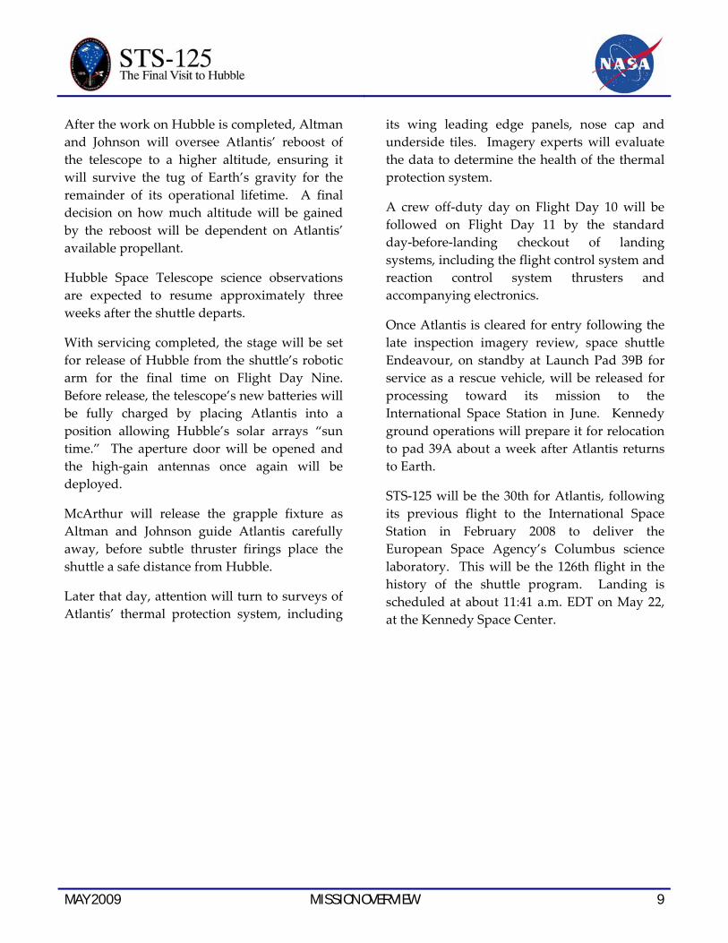
After the work on Hubble is completed, Altman and Johnson will oversee Atlantis’ reboost of the telescope to a higher altitude, ensuring it will survive the tug of Earth’s gravity for the remainder of its operational lifetime. A final decision on how much altitude will be gained by the reboost will be dependent on Atlantis’ available propellant.
Hubble Space Telescope science observations are expected to resume approximately three weeks after the shuttle departs.
With servicing completed, the stage will be set for release of Hubble from the shuttle’s robotic arm for the final time on Flight Day Nine. Before release, the telescope’s new batteries will be fully charged by placing Atlantis into a position allowing Hubble’s solar arrays “sun time.” The aperture door will be opened and the high‐gain antennas once again will be deployed.
McArthur will release the grapple fixture as Altman and Johnson guide Atlantis carefully away, before subtle thruster firings place the shuttle a safe distance from Hubble.
Later that day, attention will turn to surveys of Atlantis’ thermal protection system, including
its wing leading edge panels, nose cap and underside tiles. Imagery experts will evaluate the data to determine the health of the thermal protection system.
A crew off‐duty day on Flight Day 10 will be followed on Flight Day 11 by the standard day‐before‐landing checkout of landing systems, including the flight control system and reaction control system thrusters and accompanying electronics.
Once Atlantis is cleared for entry following the late inspection imagery review, space shuttle Endeavour, on standby at Launch Pad 39B for service as a rescue vehicle, will be released for processing toward its mission to the International Space Station in June. Kennedy ground operations will prepare it for relocation to pad 39A about a week after Atlantis returns to Earth.
STS‐125 will be the 30th for Atlantis, following its previous flight to the International Space Station in February 2008 to deliver the European Space Agency’s Columbus science laboratory. This will be the 126th flight in the history of the shuttle program. Landing is scheduled at about 11:41 a.m. EDT on May 22, at the Kennedy Space Center.

10 MISSION OVERVIEW MAY 2009
The space shuttle Atlantis, backdropped over a colorful Earth, is pictured after it undocked from the International Space Station in 2006.

MAY 2009 STS-400 11
SPACE SHUTTLE ENDEAVOUR (STS-400) TO THE RESCUE – IF REQUIRED
Unlike shuttle missions to the International Space Station, which can sustain a stranded crew for up to 90 days, space shuttle Atlantis’ flight to the Hubble Space Telescope offers no additional supplies other than those carried aboard the orbiter.
Since Hubble is in a different orbit than the space station, a second shuttle – Endeavour – sits on standby at Launch Complex 39B to serve
as a rescue vehicle in the unlikely event Atlantis is unable to return home safely. It will be the first time since October 2008 that shuttles have simultaneously occupied both launch pads.
While Endeavour is readied for launch, Atlantis’ crew would conserve as much power and oxygen on board to extend its life for as much as 25 days.

12 STS-400 MAY 2009
Designated STS‐400, the rescue mission of Endeavour would launch with four astronauts – the flight deck crew from the STS‐126 mission. Chris Ferguson would be the commander, Eric Boe would be pilot, and Shane Kimbrough and Steve Bowen would be mission specialists. The middeck would be reserved for the return of the seven Atlantis crew members.
Following launch, Endeavour’s crew will spend launch day checking out the rendezvous equipment to be used the next day as well as testing the robotic arm for the grapple of Atlantis.
Endeavour would rendezvous from beneath Atlantis approximately 23 hours after launch with pilot Boe using the robot arm to grapple a fixture on the forward end of the Orbiter Boom and Sensor System mounted along the right side of Atlantis’ payload bay.
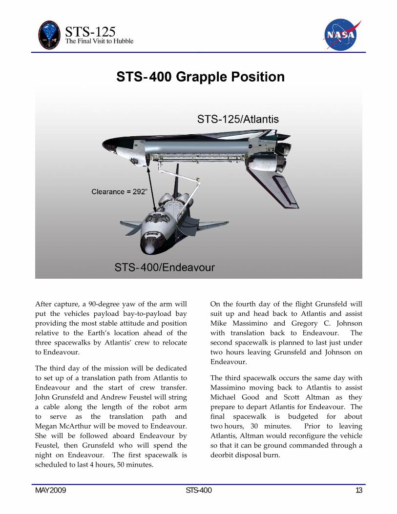
The grapple occurs with the payload bay of each vehicle pointed toward each other with the orbiters perpendicular to one another for clearance. The distance between the two at grapple would be about 24 feet.
MAY 2009 STS-400 13
After capture, a 90‐degree yaw of the arm will put the vehicles payload bay‐to‐payload bay providing the most stable attitude and position relative to the Earth’s location ahead of the three spacewalks by Atlantis’ crew to relocate to Endeavour.
The third day of the mission will be dedicated to set up of a translation path from Atlantis to Endeavour and the start of crew transfer. John Grunsfeld and Andrew Feustel will string a cable along the length of the robot arm to serve as the translation path and Megan McArthur will be moved to Endeavour. She will be followed aboard Endeavour by Feustel, then Grunsfeld who will spend the night on Endeavour. The first spacewalk is scheduled to last 4 hours, 50 minutes.
On the fourth day of the flight Grunsfeld will suit up and head back to Atlantis and assist Mike Massimino and Gregory C. Johnson with translation back to Endeavour. The second spacewalk is planned to last just under two hours leaving Grunsfeld and Johnson on Endeavour.
The third spacewalk occurs the same day with Massimino moving back to Atlantis to assist Michael Good and Scott Altman as they prepare to depart Atlantis for Endeavour. The final spacewalk is budgeted for about two hours, 30 minutes. Prior to leaving Atlantis, Altman would reconfigure the vehicle so that it can be ground commanded through a deorbit disposal burn.
14 STS-400 MAY 2009
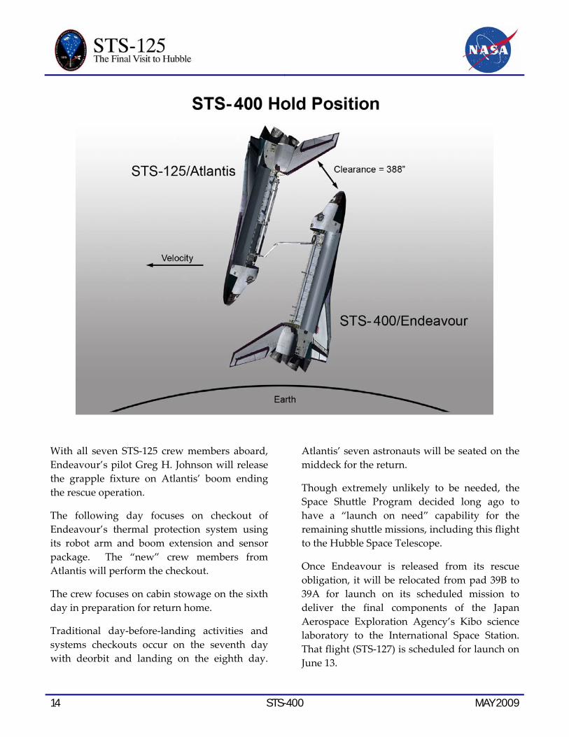
With all seven STS‐125 crew members aboard, Endeavour’s pilot Greg H. Johnson will release the grapple fixture on Atlantis’ boom ending the rescue operation.
The following day focuses on checkout of Endeavour’s thermal protection system using its robot arm and boom extension and sensor package. The “new” crew members from Atlantis will perform the checkout.
The crew focuses on cabin stowage on the sixth day in preparation for return home.
Traditional day‐before‐landing activities and systems checkouts occur on the seventh day with deorbit and landing on the eighth day.
Atlantis’ seven astronauts will be seated on the middeck for the return.
Though extremely unlikely to be needed, the Space Shuttle Program decided long ago to have a “launch on need” capability for the remaining shuttle missions, including this flight to the Hubble Space Telescope.
Once Endeavour is released from its rescue obligation, it will be relocated from pad 39B to 39A for launch on its scheduled mission to deliver the final components of the Japan Aerospace Exploration Agency’s Kibo science laboratory to the International Space Station. That flight (STS‐127) is scheduled for launch on June 13.
MAY 2009 STS-400 15
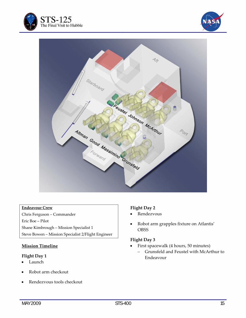
Endeavour Crew Chris Ferguson – Commander Eric Boe – Pilot Shane Kimbrough – Mission Specialist 1 Steve Bowen – Mission Specialist 2/Flight Engineer
Mission Timeline
Flight Day 1 • Launch
• Robot arm checkout
• Rendezvous tools checkout
Flight Day 2 • Rendezvous
• Robot arm grapples fixture on Atlantis’ OBSS
Flight Day 3 • First spacewalk (4 hours, 50 minutes)
− Grunsfeld and Feustel with McArthur to Endeavour
16 STS-400 MAY 2009
Flight Day 4 • Second spacewalk (1 hour, 45 minutes)
− Grunsfeld to Atlantis − Grunsfeld and Massimino with Johnson
to Endeavour − Massimino back to Atlantis
• Third spacewalk (2 hours, 30 minutes) − Massimino with Good and Altman to
Endeavour
• Release of Atlantis
• Separation burn
Flight Day 5 • OBSS survey of Endeavour’s Thermal
Protection System
• Crew off duty
Flight Day 6 • Crew cabin survey
• Crew off duty
Flight Day 7 • Flight Control System checkout
• Reaction Control System hotfire test
• Entry seating setup
• Cabin Stow
Flight Day 8 • Deorbit
• Landing

MAY 2009 TIMELINE OVERVIEW 17
STS-125 TIMELINE OVERVIEW
Flight Day 1
• Launch
• Payload Bay Door Opening
• Ku-Band Antenna Deployment
• Shuttle Robotic Arm Activation
• Space Support Equipment Checkout
• Umbilical Well and Handheld External Tank Video and Stills Downlink
Flight Day 2
• Atlantis Thermal Protection System Survey with Orbiter Boom Sensor System
• Extravehicular Mobility Unit Checkout
• Payload Bay Flight Support System Preparations
• Rendezvous Tools Checkout
• HST Aperture Door Closure
• HST Maneuver to Rendezvous and Grapple Attitude
• HST High Gain Antenna Retraction
Flight Day 3
• Rendezvous with the Hubble Space Telescope
• HST Solar Arrays Positioned for Grapple
• HST Grapple and Berth on Flight Support System
• Shuttle Robotic Arm Survey of HST
• EVA 1 Procedure Review
Flight Day 4
• EVA 1 by Grunsfeld and Feustel (Wide Field Camera III Installation, Science Instrument Command and Data Handling Computer, Soft Capture Mechanism Installation and Latch Over Centerline Kit Installation)
• Wide Field Camera III Aliveness Test and Checkout
• SI C&DH Aliveness Checkout
• Bay 3 Battery Checkout
• EVA 2 Procedure Review
Flight Day 5
• EVA 2 by Massimino and Good (Rate Sensor Unit Changeout and Bay 2 Battery Changeout)
• Bay 2 Battery Checkout
• Rate Sensor Unit Checkout
• EVA 3 Procedure Review
Flight Day 6
• EVA 3 by Grunsfeld and Feustel (Cosmic Origins Spectrograph replaces the Corrective Optics Space Telescope Axial Replacement known as COSTAR and the repair to the Advanced Camera for Surveys)
• Cosmic Origins Spectrograph Checkout
• ASC Checkout
• EVA 4 Procedure Review
18 TIMELINE OVERVIEW MAY 2009
Flight Day 7
• EVA 4 by Massimino and Good (Space Telescope Imaging Spectrograph refurbishment and New Outer Layer Blanket replacement over Bay 8)
• Space Telescope Imaging Spectrograph Checkout
• EVA 5 Procedure Review
Flight Day 8
• EVA 5 by Grunsfeld and Feustel (Bay 3 Battery Changeout, Fine Guidance Sensor-2 Replacement and New Outer Layer Blanket replacement over Bay 5)
• Fine Guidance Sensor-2 Checkout
• Bay 3 Battery Checkout
• Advanced Camera for Surveys and Wide Field Camera III Combined Checkout
• High Gain Antenna Deployment
• HST Reboost, if propellant permits
• Rendezvous Tools Checkout
Flight Day 9
• HST Aperture Door Opening
• Atlantis/HST Maneuver to Release Attitude
• HST Release
• Atlantis Separation Maneuver
• Flight Support System Stowage in Payload Bay
• OBSS Unberth
• OBSS Late Inspection of Atlantis Thermal Protection System
Flight Day 10
• Crew Off Duty Time
• Crew News Conference
• Atlantis/ISS Ship-to-Ship Call
Flight Day 11
• Flight Control System Checkout
• Reaction Control System Hot-Fire Test
• Cabin Stowage
• Ku-Band Antenna Stowage
Flight Day 12
• Deorbit Preparations
• Payload Bay Door Closing
• Deorbit Burn
• Kennedy Space Center Landing

MAY 2009 MISSION PROFILE 19
MISSION PROFILE CREW
Commander: Scott Altman Pilot: Gregory C. Johnson Mission Specialist 1: Michael Good Mission Specialist 2: Megan McArthur Mission Specialist 3: John Grunsfeld Mission Specialist 4: Mike Massimino Mission Specialist 5: Andrew Feustel
LAUNCH
Orbiter: Atlantis (OV‐104) Launch Site: Kennedy Space Center
Launch Pad 39A Launch Date: May 11, 2009 Launch Time: 2:01 p.m. EDT Launch Window: 42 minutes
(approximately) Altitude: 297 Nautical Miles
(342 miles) Orbital Insertion; 304 NM (350 miles) Rendezvous
Inclination: 28.5 Degrees Duration: 10 Days 20 Hours
27 Minutes
VEHICLE DATA
Shuttle Liftoff Weight: 4,519,343 pounds
Orbiter/Payload Liftoff Weight: 264,165 pounds
Orbiter/Payload Landing Weight: 226,040 pounds
Software Version: OI‐32
Space Shuttle Main Engines:
SSME 1: 2059 SSME 2: 2044 SSME 3: 2057 External Tank: ET‐130 SRB Set: BI‐137 RSRM Set: 105
SHUTTLE ABORTS
Abort Landing Sites
RTLS: Kennedy Space Center Shuttle Landing Facility
TAL: Primary –Moron, Spain AOA: Primary – Edwards Air Force Base
LANDING
Landing Date: May 22, 2009 Landing Time: 11:41 a.m. EDT Primary landing Site: Kennedy Space Center
Shuttle Landing Facility
PAYLOADS
Hubble Space Telescope Servicing Mission (HST SM4)

20 MISSION PROFILE MAY 2009
This page intentionally left blank.

MAY 2009 MISSION PRIORITIES 21
HST SERVICING MISSION PRIORITIES 1. Three Rate Sensor Unit (gyroscope) removal
and replacement
2. Wide Field Camera 3 installed in place of Wide Field Planetary Camera 2
3. Science Instrument Command & Data Handling System swap out
4. Cosmic Origins Spectrograph installation
5. Battery Module replacement installation (Bays 2 and 3)
6. Fine Guidance Sensor 2 removal and replacement
7. Remaining instrument repair
8. Space Telescope Imaging Spectrograph power supply system repair, or restore power supply for the Advanced Camera for Surveys *
9. New Outer Blanket Layer installation (Bays 8, 5 & 7)
10. Soft Capture Mechanism installation
11. Reboost Hubble Space Telescope altitude
* Choice of first instrument repair will be prioritized based on spacewalk efficiency and mission replanning scenarios

22 MISSION PRIORITIES MAY 2009
HST SERVICING MISSION SUCCESS CRITERIA
• Minimum Mission Success
− Two Rate Sensor Units (four gyroscopes)
− Wide Field Camera 3
− Science Instrument Command & Data Handling system
− Cosmic Origins Spectrograph
− Bay 2 & 3 Battery Module replacements (six new batteries)
• Full Mission Success
− Three Rate Sensor Units (five gyroscopes)
− Wide Field Camera 3
− Science Instrument Command & Data Handling system
− Cosmic Origins Spectrograph
− Bay 2 & 3 Battery Module replacements (six new batteries)
− Space Telescope Imaging Spectrograph repair, or Advanced Camera for Surveys repair
− Fine Guidance Sensor 2

MAY 2009 HST HISTORY 23
HUBBLE SPACE TELESCOPE HISTORY
The Hubble Space Telescope (HST) heads back toward its normal routine, after a week of servicing and upgrading by the STS-109 astronaut crew in 2002.
HUBBLE PROGRAM
Launched in April 1990 and poised for many more years of trailblazing science ranging from our own solar system to the edge of the observable universe, NASA’s Hubble Space Telescope is fulfilling the hopes astronomers have long held for a large, optically superb telescope orbiting above the Earth’s distorting atmosphere and providing uniquely clear and deep views of the cosmos.
The only one of NASA’s four “Great Observatories” (Hubble, Compton Gamma-Ray Observatory, Chandra X-Ray Observatory, and Spitzer Space Telescope) that is serviceable by space shuttle astronauts, Hubble has seen its
capabilities grow immensely in its 18 historic years of operation. This has been the direct result of the installation of new, cutting-edge scientific instruments and more powerful engineering components. Replacement of aging or failed parts has been an important aspect of servicing and has been responsible for the telescope’s longevity.
All of the Great Observatories have a particular range of light or electromagnetic radiation to which they are designed and are sensitive. Hubble’s domain extends from the ultraviolet, through the visible (to which human eyes are sensitive), and to the near-infrared. In terms of the wavelength of light, Hubble’s coverage ranges from 1,200 Angstroms in the ultraviolet

24 HST HISTORY MAY 2009
(1 Angstrom = 1 hundred-millionth of a centimeter) to 2.4 microns (24,000 Angstroms) in the near-infrared. Hubble’s UV-to-near-IR spectral range is a key piece of “astronomical real estate” – a dominant range of wavelengths emitted by stars and galaxies – and Hubble takes advantage of this access with both imaging and spectroscopy.
Compared to ground-based telescopes, Hubble is not particularly large. With a primary mirror diameter of 2.4 meters (94.5 inches), Hubble would at most be considered a medium-size telescope on the ground. However, the combination of its precision optics, location above the atmosphere, state-of-the-art instrumentation, and unprecedented pointing stability and control, allows Hubble to more than make up for its lack of size. The most detailed look at the farthest known galaxies in the universe has been obtained by imaging from the Hubble Space Telescope. Spectroscopically, Hubble has detected several atomic constituents in the atmosphere of a planet outside our solar system, an enormously difficult measurement and a first in this critical and growing field whose ultimate aim is to look for places elsewhere in the universe where the conditions for life exist.
On Jan. 16, 2004, NASA Administrator Sean O’Keefe announced the cancellation of the final scheduled servicing mission to Hubble. The review board studying the shuttle Columbia disaster recommended that all future space shuttle missions fly in orbits that allow them to reach the International Space Station in case of an emergency. The orbit a shuttle would need to follow to service Hubble would not allow the shuttle to get to the station.
However, during a meeting with agency employees at NASA’s Goddard Space Flight
Center on Oct. 31, 2006, NASA Administrator Michael Griffin announced there would indeed be a fifth and final servicing mission to Hubble.
In making the announcement, Griffin said, “We have conducted a detailed analysis of the performance and procedures necessary to carry out a successful Hubble repair mission over the course of the last three shuttle missions. What we have learned has convinced us that we are able to conduct a safe and effective servicing mission to Hubble. While there is an inherent risk in all spaceflight activities, the desire to preserve a truly international asset like the Hubble Space Telescope makes doing this mission the right course of action.”
Previous Servicing Missions
The STS-125/HST-SM4 mission was originally planned for an Oct. 14, 2008 launch. Space shuttle Atlantis and her 22,000 pounds of Hubble cargo were in the final days of launch preparations, when the “A” side of the Science Instrument Command and Data Handling (SI C&DH) system suffered a permanent electronic failure on Sept. 27, 2008. The SI C&DH provides all of the electronics to command Hubble’s science instruments from the ground and to flow science and engineering data back to the ground. Because this system is such a critical part of Hubble’s science capability, the mission was postponed in order to allow engineers enough time to prepare the spare SI C&DH for inclusion into the servicing mission. Meanwhile, in order to restore science operations to the orbiting telescope, flight controllers on the ground successfully switched to the “B” side of the SI C&DH electronics and several additional spacecraft data system modules.
MAY 2009 HST HISTORY 25
Servicing Mission 1, December 1993: The primary goal of Servicing Mission 1 was to restore Hubble’s vision. Because Hubble’s primary mirror was incorrectly shaped, the telescope could not focus all the light from an object to a single sharp point. Instead, it saw a fuzzy halo around objects it observed. Astronauts on space shuttle Endeavour’s STS-61 mission spent five days tuning it up. They installed two new devices – the Wide Field and Planetary Camera 2 and the Corrective Optics Space Telescope Axial Replacement – to compensate for the primary mirror’s incorrect shape. Astronauts also installed new solar arrays, to reduce the jitter caused by excessive flexing of the solar panels during the telescope’s orbital transition from cold darkness into warm daylight, and new gyroscopes to help point and track the telescope, along with fuse plugs and electronic units.
Servicing Mission 2, February 1997: During the 10-day mission (STS-82), astronauts aboard the space shuttle Discovery installed two technologically advanced instruments. The Near Infrared Camera and Multi-Object Spectrometer (NICMOS) enabled Hubble to observe infrared wavelengths, crucial for viewing very distant optical sources that have lost energy traveling across most of the visible universe and now radiate in the infrared band. The second instrument, the Space Telescope Imaging Spectrograph (STIS), could take detailed pictures of celestial objects and hunt for black holes. Both instruments featured technology that wasn’t available when scientists designed and built the original Hubble instruments in the late 1970s. Astronauts also installed a refurbished Fine Guidance Sensor, one of three essential instruments used to keep Hubble steady while
viewing objects and to calculate celestial distances; a Solid State Recorder to replace one of Hubble’s data recorders; and a refurbished, spare Reaction Wheel Assembly, part of the Pointing Control Subsystem.
Servicing Mission 3A, December 1999: NASA decided to split the third servicing mission into two parts, SM3A and SM3B, after the third of Hubble’s six gyroscopes failed. Hubble normally needs three gyroscopes to observe a target. Astronauts aboard space shuttle Discovery (STS-103) replaced all six gyroscopes, as well as one of Hubble’s three fine guidance sensors that are used to keep Hubble steady while viewing objects. The astronauts also installed a transmitter, an advanced central computer, a digital data recorder, an electronics enhancement kit, battery improvement kits and new outer layers of thermal protection. Shortly before the 3A mission, Hubble was placed into “safe-mode” after a fourth gyroscope failed unexpectedly. In safe-mode Hubble is in a sort of protective hibernation and cannot observe objects.
Servicing Mission 3B, March 2002: Astronauts aboard space shuttle Columbia (STS-109) installed several new instruments on Hubble that vastly improved the observatory’s capability. Astronauts performed five spacewalks. Their principal task was to install the Advanced Camera for Surveys (ACS). With its wide field of view, sharp image quality and enhanced sensitivity, ACS could collect data 10 times faster than the Wide Field and Planetary Camera 2, the telescope’s earlier surveying instrument. The ACS brought the then 12-year-old telescope into the 21st century. The ACS was quickly used to capture the most distant image of the universe, called the Hubble Ultra Deep Field. The 8-year-old solar array panels were replaced with smaller rigid ones
26 HST HISTORY MAY 2009
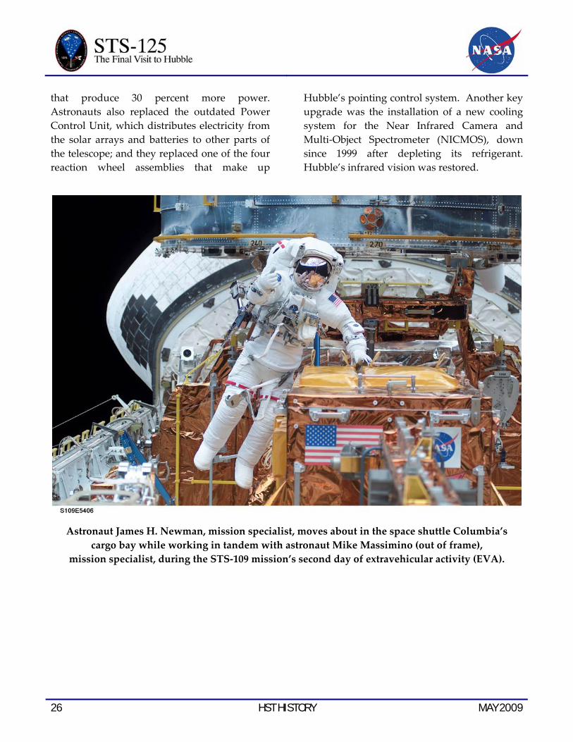
Astronaut James H. Newman, mission specialist, moves about in the space shuttle Columbia’s cargo bay while working in tandem with astronaut Mike Massimino (out of frame),
mission specialist, during the STS-109 mission’s second day of extravehicular activity (EVA).
that produce 30 percent more power. Astronauts also replaced the outdated Power Control Unit, which distributes electricity from the solar arrays and batteries to other parts of the telescope; and they replaced one of the four reaction wheel assemblies that make up
Hubble’s pointing control system. Another key upgrade was the installation of a new cooling system for the Near Infrared Camera and Multi-Object Spectrometer (NICMOS), down since 1999 after depleting its refrigerant. Hubble’s infrared vision was restored.
MAY 2009 HST HISTORY 27
Best of Hubble Science
As the 12.5-ton Earth-orbiting observatory looks into space, unburdened by atmospheric distortion, new details about planets, stars and galaxies come into crystal clear view. The telescope has produced a vast amount of information and a steady stream of images that have astounded the world’s astronomical community and the public as well. It has helped confirm some astronomical theories, challenged others and often come up with complete surprises for which theories do not yet exist.
Hubble provides four basic capabilities:
• High angular resolution – the ability to image fine detail.
• High sensitivity – the ability to detect very faint objects.
• Ultraviolet performance – the ability to produce ultraviolet images and spectra.
• Infrared performance – the ability to produce infrared images and spectra.
Each year the Space Telescope Science Institute (STScI) receives approximately a thousand new observing proposals from astronomers around the world. Observing cycles are routinely over-subscribed by a factor of six.
The telescope is extremely popular because it allows scientists to get their clearest view ever of the cosmos and to obtain information on the temperature, density, composition and motion of celestial objects by analyzing the radiation they emit or absorb. On average 14 scientific papers per week, based on Hubble observations, are published in scholarly journals. Results of Hubble observations are presented regularly at meetings of the
American Astronomical Society and other major scientific conferences.
Although Hubble’s dramatic findings to date are too numerous to be described fully, the following paragraphs highlight some of the significant astronomical discoveries and observations in three basic categories:
• Galaxies and cosmology
• Formation and evolution of stars and planets
• Earth’s Solar System.
For further information, visit the STScI Web site at http://hubblesite.org/newscenter.
Galaxies and Cosmology
Deepest View Ever of the Universe Unveils Earliest Galaxies http://hubblesite.org/newscenter/archive/releases/2004/07
In a tiny patch of sky just one-tenth the diameter of the full moon, the Hubble Space Telescope revealed an estimated 10,000 galaxies. Called the Hubble Ultra Deep Field (HUDF), the million-second-long exposure reveals the first galaxies to emerge from the so-called “dark ages,” the time shortly after the big bang when the first stars reheated the relatively cool and opaque hydrogen and helium gas produced in the big bang, making it transparent to light. The image offers new insights into what types of objects reheated the universe long ago leading ultimately to the universe as seen today.

28 HST HISTORY MAY 2009
The sharpest image ever taken of the large “grand design” spiral galaxy M81 released at the American Astronomical Society Meeting in Honolulu, Hawaii. This beautiful galaxy is tilted at
an oblique angle on to our line of sight, giving a bird’s-eye view of the spiral structure.
The historic view is actually two separate sets of images taken by Hubble’s Advanced Camera for Surveys (ACS) and the Near Infrared Camera and Multi-object Spectrometer (NICMOS) and stacked together to form a single extremely deep time exposure. The resulting composite image, the HUDF, reveals galaxies that are too faint to be seen by ground-based telescopes, or even in Hubble’s previous faraway looks, called the Hubble Deep Fields (HDF’s), taken in 1995 and 1998. In ground-based images, the patch of sky in which the galaxies reside is largely empty. Located in the
constellation Fornax, the region is below the constellation Orion.
The combination of ACS and NICMOS images has been used to search for developing galaxies that were formed within the first billion years after the big bang, which occurred 13.7 billion years ago. To date, more than 500 objects have been detected in the HUDF that emitted the light we see with Hubble when the universe was less than one billion years old (at a redshift of 6 or greater.). At least one galaxy has been detected at a redshift of 7.4. Light from this
MAY 2009 HST HISTORY 29
object started its journey toward us some 700 million years after the big bang, when the universe was five percent of its current age. A key question for HUDF astronomers is in what respects the universe appeared different at this very early time, when star formation had just begun, than it did when the cosmos was between one and two billion years old, at which time the rate of star formation in the universe had dropped to a very low value.
HUDF observations began Sept. 24, 2003, and continued through Jan. 16, 2004. The ACS, which is the size of a phone booth, captured ancient photons of light that began traversing the universe even before Earth existed. Photons of light from the very faintest objects arrived at a trickle of one photon per minute, compared with millions of photons per minute from nearer galaxies.
Evolution of Stars and Planets
Light Echo from Erupting Star http://hubblesite.org/newscenter/archive/releases/star/2004/10/
In January 2002, a dull star in an obscure constellation suddenly became 600,000 times more luminous than our sun, temporarily making it one of the brightest stars in our Milky Way galaxy.
The mysterious star has long since faded back to obscurity, but Hubble observations of a phenomenon called a “light echo” have uncovered remarkable new features. These details have provided astronomers a CAT-scan-like probe of the three-dimensional structure of shells of dust surrounding an aging star.
Astronomers used the Hubble images to determine that the ill-tempered star, called V838 Monocerotis (V838 Mon), is about
20,000 light-years from Earth. The star puts out enough energy in a brief flash to illuminate surrounding dust. The star presumably ejected the illuminated dust shells in previous outbursts. Light from the latest outburst travels to the dust and then is reflected to Earth. Because of this indirect path, the light arrives at Earth months after light coming directly toward Earth from the star itself.
The outburst of V838 Mon was somewhat similar to that of a nova, a more common stellar outburst. A typical nova is a normal star that dumps hydrogen onto a compact white-dwarf companion star. The hydrogen piles up until it spontaneously explodes by nuclear fusion – like a titanic hydrogen bomb. This exposes a searing stellar core, which has a temperature of hundreds of thousands of degrees Fahrenheit.
By contrast, however, V838 Mon evidently did not expel its outer layers. Instead, it grew enormously in size, with its surface temperature dropping to temperatures not much hotter than a light bulb and its color becoming extremely red. This behavior of ballooning to an immense size but not losing its outer layers is very unusual and completely unlike an ordinary nova explosion.
V838 Mon is so unique it may represent a transitory stage in a star’s evolution that is rarely seen. The star has some similarities to highly unstable aging stars called eruptive variables, which suddenly and unpredictably increase in brightness.
The circular light-echo feature now has expanded to twice the angular size of Jupiter on the sky. Astronomers expect that it will continue expanding as reflected light from farther out in the dust envelope finally arrives at Earth.

30 HST HISTORY MAY 2009
Earth’s Solar System
Hubble Looks for Possible Moon Resources http://hubblesite.org/newscenter/archive/releases/2005/29
When Americans return to the moon, they will have the Hubble Space Telescope to thank for a new class of scientific observations of Earth’s nearest celestial neighbor.
Hubble’s resolution and sensitivity to ultraviolet light have allowed it to search for important oxygen-bearing minerals on the moon. Since the moon does not have a breathable atmosphere, minerals such as ilmenite (titanium and iron oxide) may be critical for a sustained human lunar presence. Ilmenite is a potential source of oxygen for breathing or powering rockets.
The new Hubble observations are the first high-resolution, ultraviolet images ever acquired of the moon. The images provide scientists with a new tool to study mineral variations within the lunar crust. Such data, in combination with other measurements, will help ensure the most valuable sites are targeted for future robotic and human missions.
In 2005, Hubble’s Advanced Camera for Surveys captured ultraviolet and visible light images of known geologically diverse areas on the side of the moon nearest Earth. These included the Aristarchus impact crater and the adjacent Schroter’s Valley, which neither humans nor robotic spacecraft have visited. Hubble also photographed the Apollo 15 and 17 landing sites, where astronauts collected rock and soil samples in 1971 and 1972.
Scientists are comparing the properties of the rock and soil samples from the Apollo sites with the new Hubble images. The telescope’s
observations of Aristarchus crater and Schroter’s Valley will help refine researchers’ understanding of the diverse, scientifically interesting materials in the region and unravel their full resource potential.
Summary
Astronauts Steven L. Smith, and John Grunsfeld appear as small figures in this
wide scene photographed during extravehicular activity during STS-103 in 1999.
The Hubble Space Telescope has established itself as a premier astronomical observatory that continues to make dramatic observations and discoveries at the forefront of astronomy. Among a long list of achievements:
• Hubble’s ability to detect faint supernovae contributed to the discovery that the expansion rate of the universe is accelerating, indicating the existence of mysterious “dark energy” in space.
• Observations of Cepheid variable stars in nearby galaxies were used to establish the

MAY 2009 HST HISTORY 31
current expansion rate of the universe to better than 10 percent accuracy.
• The Hubble Ultra Deep Field provided our deepest view yet into the universe’s distant past, allowing us to reconstruct how galaxies evolve and grow by swallowing other galaxies.
• Hubble provided the first direct measurements of the three-dimensional distribution of Dark Matter in space.
• Peering into nearby regions of star birth in the Milky Way galaxy, Hubble has revealed flattened disks of gas and dust that are the likely birthplaces of new planets.
• When sun-like stars end their lives, they eject spectacular nebulae. Hubble has revealed fantastic and enigmatic details of this process
• Hubble made detailed measurements of a Jupiter-sized planet orbiting a nearby star, including the first detection of the atmosphere of an extrasolar planet.
• The explosive collision of comet Shomaker-Levy/9 with Jupiter gave Earthlings a cautionary tale of the danger posed by cometary impacts.
• Hubble observations have shown that monster black holes, with masses millions to billions times the mass of our sun, inhabit the centers of most galaxies
• Hubble played a key role in determining the distances and energies of gamma-ray bursts, showing that they are the most powerful explosions in the universe other than the big bang itself.
After Servicing Mission 4, the telescope will view the universe with significantly expanded scientific capabilities from the new Wide Field Camera 3 and the new Cosmic Origins Spectrograph, as well as the reactivated Advanced Camera for Surveys and Space Telescope Imaging Spectrograph. These additions and the upgrades to Hubble’s operating hardware hold the promise of momentous discoveries in the years ahead.

32 HST HISTORY MAY 2009
This page intentionally left blank
MAY 2009 FLIGHT CONTROL 33
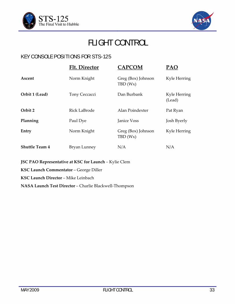
FLIGHT CONTROL KEY CONSOLE POSITIONS FOR STS-125
Flt. Director CAPCOM PAO
Ascent Norm Knight Greg (Box) Johnson TBD (Wx)
Kyle Herring
Orbit 1 (Lead) Tony Ceccacci Dan Burbank Kyle Herring (Lead)
Orbit 2 Rick LaBrode Alan Poindexter Pat Ryan
Planning Paul Dye Janice Voss Josh Byerly
Entry Norm Knight Greg (Box) Johnson TBD (Wx)
Kyle Herring
Shuttle Team 4 Bryan Lunney N/A N/A
JSC PAO Representative at KSC for Launch – Kylie Clem
KSC Launch Commentator – George Diller
KSC Launch Director – Mike Leinbach
NASA Launch Test Director – Charlie Blackwell-Thompson

34 FLIGHT CONTROL MAY 2009
KEY CONSOLE POSITIONS FOR STS-400
Flt. Director CAPCOM PAO
Ascent Norm Knight Greg (Box) Johnson TBD (Wx)
Kyle Herring
Orbit 1 (Lead) Paul Dye Steve Robinson Kyle Herring (Lead)
Orbit 2 Mike Sarafin Greg (Box) Johnson Pat Ryan
Planning Richard Jones Janice Voss Josh Byerly
Entry Norm Knight Greg (Box) Johnson TBD (Wx)
Kyle Herring
Shuttle Team 4 Bryan Lunney N/A N/A
JSC PAO Representative at KSC for Launch – TBD
KSC Launch Commentator – George Diller
KSC Launch Director – Mike Leinbach
NASA Launch Test Director – Jeff Spaulding

MAY 2009 CREW 35
STS-125 ATLANTIS CREW This STS-125/SM4 crew patch shows the Hubble Space Telescope along with a representation of its many scientific discoveries. The overall structure and composition of the universe is shown in blue and filled with planets, stars and galaxies.
The black background is indicative of the mysteries of dark-energy and dark-matter. The new instruments to be installed on Hubble during this mission, Wide Field Camera-3 and the Cosmic Origins Spectrograph, will make observations to help understand these unseen components that seem to dominate the structure of the universe.
The red border of the patch represents the red-shifted glow of the early universe and the limit of the Hubble's view into the cosmos. Upon completion of STS-125/SM4, the fifth mission to service Hubble, the telescope will provide even deeper and more detailed views of the universe.
Soaring by the telescope is the space shuttle, which initially deployed Hubble and has enabled astronauts to continually upgrade the telescope, significantly contributing to the expansion of human knowledge.

36 CREW MAY 2009
These seven astronauts take a break from training to pose for the STS-125/SM4 crew portrait.
From the left are astronauts Mike Massimino, Michael Good, both mission specialists; Gregory C. Johnson, pilot; Scott Altman, commander; Megan McArthur,
John Grunsfeld and Andrew Feustel, all mission specialists. Short biographical sketches of the crew follow with detailed background available at:
http://www.jsc.nasa.gov/Bios/

MAY 2009 CREW 37
STS-125 CREW BIOGRAPHIES
Scott Altman
Retired Navy Capt. Scott Altman will lead the crew of STS-125/SM4 on the fifth and final shuttle mission planned to service the Hubble Space Telescope. Altman served as the pilot on STS-90 in 1998 and STS-106 in 2000. He was the commander of STS-109 in 2002, the fourth Hubble servicing mission. He has overall responsibility for the safety and execution of
this mission, orbiter systems operations and flight operations, including landing. He will fly Atlantis through its rendezvous and capture of the space telescope and will fly the shuttle during Hubble’s release. Altman will be involved in the robotic inspection of Atlantis’ heat shield.
38 CREW MAY 2009
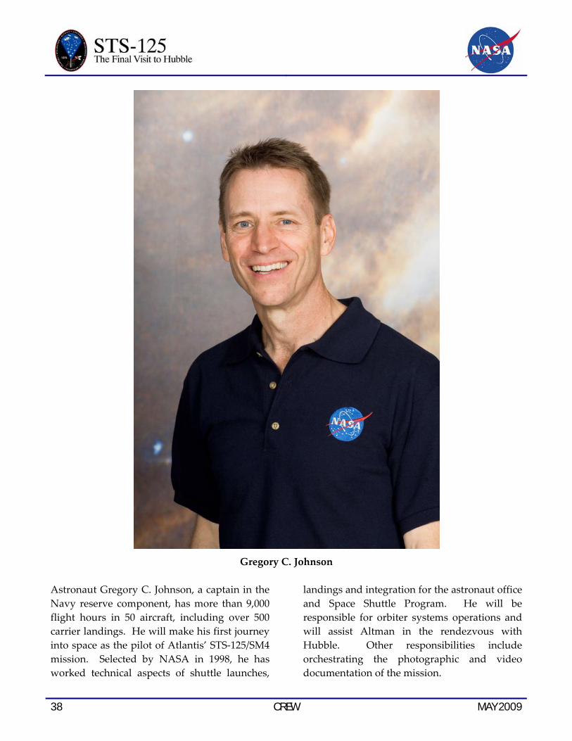
Gregory C. Johnson
Astronaut Gregory C. Johnson, a captain in the Navy reserve component, has more than 9,000 flight hours in 50 aircraft, including over 500 carrier landings. He will make his first journey into space as the pilot of Atlantis’ STS-125/SM4 mission. Selected by NASA in 1998, he has worked technical aspects of shuttle launches,
landings and integration for the astronaut office and Space Shuttle Program. He will be responsible for orbiter systems operations and will assist Altman in the rendezvous with Hubble. Other responsibilities include orchestrating the photographic and video documentation of the mission.
MAY 2009 CREW 39
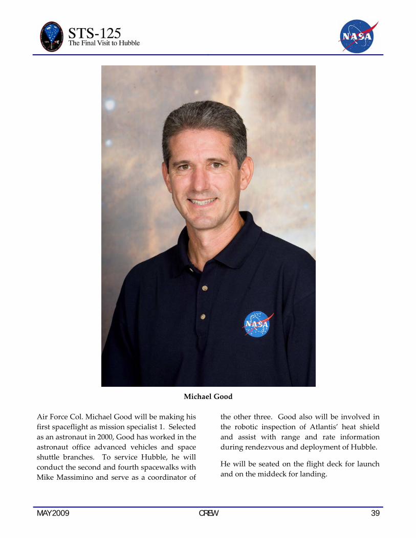
Michael Good
Air Force Col. Michael Good will be making his first spaceflight as mission specialist 1. Selected as an astronaut in 2000, Good has worked in the astronaut office advanced vehicles and space shuttle branches. To service Hubble, he will conduct the second and fourth spacewalks with Mike Massimino and serve as a coordinator of
the other three. Good also will be involved in the robotic inspection of Atlantis’ heat shield and assist with range and rate information during rendezvous and deployment of Hubble.
He will be seated on the flight deck for launch and on the middeck for landing.

40 CREW MAY 2009
Megan McArthur
Astronaut Megan McArthur will be making her first spaceflight as mission specialist 2. She has a doctorate in oceanography from the Scripps Institution of Oceanography, University of California-San Diego. Selected in 2000, McArthur has worked in the astronaut office space shuttle branch, served as a crew support astronaut for Expedition 9 and worked as a
spacecraft communicator in Mission Control. She will be responsible for the robotic arm operations during the capture and release of Hubble, as well as during the spacewalks and Atlantis’ heat shield inspections. She also will serve as the flight engineer, assisting Altman and Johnson on the flight deck during ascent and landing.

MAY 2009 CREW 41
John Grunsfeld
Astronaut John Grunsfeld will be making his third trip to Hubble and his fifth spaceflight, serving as mission specialist 3. He has a doctorate in physics from the University of Chicago and has conducted research in X-ray and gamma-ray astronomy, high-energy cosmic ray studies and development of new detectors and instrumentation. He performed five spacewalks to service the telescope on STS-103 in 1999 and STS-109 in 2002. He also flew on
STS-67 in 1995 and STS-81 in 1997. Grunsfeld is the payload commander on STS-125/SM4, responsible for the telescope’s systems. He will lead the team of spacewalkers on the five excursions to service Hubble, conducting the first, third and fifth spacewalks with Andrew Feustel. They will serve as coordinators for the other two spacewalks. Grunsfeld will be on the middeck for launch and landing.
42 CREW MAY 2009
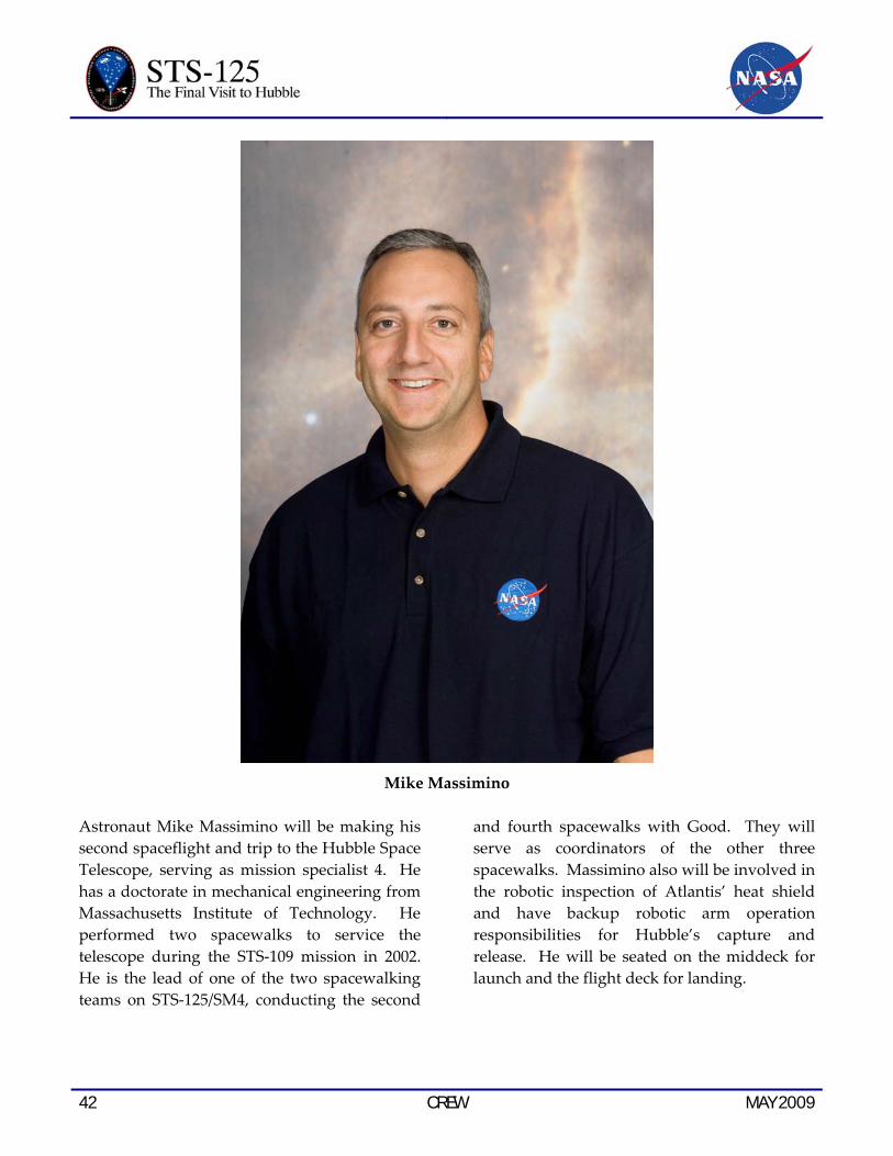
Mike Massimino
Astronaut Mike Massimino will be making his second spaceflight and trip to the Hubble Space Telescope, serving as mission specialist 4. He has a doctorate in mechanical engineering from Massachusetts Institute of Technology. He performed two spacewalks to service the telescope during the STS-109 mission in 2002. He is the lead of one of the two spacewalking teams on STS-125/SM4, conducting the second
and fourth spacewalks with Good. They will serve as coordinators of the other three spacewalks. Massimino also will be involved in the robotic inspection of Atlantis’ heat shield and have backup robotic arm operation responsibilities for Hubble’s capture and release. He will be seated on the middeck for launch and the flight deck for landing.

MAY 2009 CREW 43
Andrew Feustel
Astronaut Andrew Feustel will be making his first trip into space, serving as mission specialist 5. He has a doctorate in geological sciences from Queen’s University. Selected as an astronaut in 2000, he has worked in the astronaut office space shuttle and space station branches. On STS-125/SM4, Feustel will perform the first, third and fifth spacewalks
with Grunsfeld. They will serve as coordinators for the other two spacewalks. Feustel also will assist with range and rate information during rendezvous and deployment of Hubble and be responsible for Atlantis' onboard computing network throughout the flight. Feustel will be on the middeck for launch and landing.

44 CREW MAY 2009
This page intentionally left blank.

MAY 2009 PAYLOAD OVERVIEW 45
PAYLOAD OVERVIEW
HUBBLE SERVICING MISSION PAYLOAD BAY HARDWARE
There will be four support structures flying in Atlantis’s cargo bay that will carry the science instruments, flight hardware, support equipment and tools to be used during the mission.
• Flight Support System (FSS)
• Super Lightweight Interchangeable Carrier (SLIC)
• Multi-Use Lightweight Equipment (MULE) Carrier
• Orbital Replacement Unit Carrier (ORUC)
FLIGHT SUPPORT SYSTEM (FSS)
The Flight Support System (FSS) is a reusable equipment system that provides the structural, mechanical, and electrical interfaces between a spacecraft and the orbiter for launch, retrieval, and in-orbit servicing missions. It also served as the maintenance platform holding Hubble in place while providing a means for rotation about two axes for correct positioning during deployment and in-orbit servicing.
The FSS configuration for spacecraft deployment or retrieval consists of three structural cradles, mechanisms for spacecraft retention and positioning, and avionics. The cradles provide the structural support for the payload and storage locations for tools and electronics. The mechanisms for retention and positioning allow the spacecraft to be docked to the FSS, serviced, and released. The FSS provides the electrical interface between the
orbiter and the Hubble, and between the orbiter and the servicing mission payload elements. The avionics provide all necessary power, command, control, and data monitoring interfaces to support operational modes of the spacecraft. The avionics also provide for remote control of all FSS mechanisms from the orbiter aft flight deck. The configuration for in-orbit servicing typically consists of one cradle with Berthing and Positioning System, mechanisms, and avionics.
The FSS has a specific configuration for servicing the Hubble Space Telescope. The Hubble servicing configuration consists of a single cradle, avionics, mechanisms, and the Berthing and Positioning System (BAPS). Once Hubble is berthed to the FSS, the BAPS is used to orient the Hubble for servicing and to react to loads induced by reboosting Hubble to a higher orbit. The avionics and mechanisms used for Hubble servicing are a subset of the full complement available, with additional power capability.
SOFT CAPTURE AND RENDEZVOUS SYSTEM (SCRS)
Preparing for the Future
When the Hubble Space Telescope reaches the end of its life, NASA will need to deorbit it safely using a next-generation space transportation vehicle.
Originally planned for Earth return on the shuttle, Hubble’s scientific life will now extend beyond the planned retirement date of the shuttle in 2010. As part of Servicing Mission 4, engineers have developed the Soft Capture and.

46 PAYLOAD OVERVIEW MAY 2009
The Soft Capture Mechanism is readied for STS-125 at Goddard Space Flight Center.
Rendezvous System, or SCRS, which will enable the future rendezvous, capture, and safe disposal of Hubble by either a crewed or robotic mission. The SCRS greatly increases the current shuttle capture envelop interfaces on Hubble, therefore significantly reducing the rendezvous and capture design complexities associated with the disposal mission.
The SCRS is comprised of the Soft Capture Mechanism (SCM) system and the Relative Navigation System (RNS).
The Soft Capture Mechanism
The Soft Capture Mechanism (SCM) will launch on a turn-table like piece of equipment called
the Flight Support System (FSS) within the cargo bay of the shuttle. The FSS serves as the berthing platform for Hubble and provides all electrical and mechanical interfaces between the shuttle and the telescope while Hubble is docked.
The SCM uses a Low Impact Docking System (LIDS) interface and associated relative navigation targets for future rendezvous, capture, and docking operations. The system’s LIDS interface is designed to be compatible with the rendezvous and docking systems to be used on the next-generation space transportation vehicle

MAY 2009 PAYLOAD OVERVIEW 47
During the mission, astronauts will attach the SCM to Hubble. About 72 inches in diameter and 2 feet high, the SCM will sit on the bottom of Hubble, inside the FSS berthing and positioning ring, without affecting the normal FSS-to-Hubble interfaces. It will be attached onto the telescope by three sets of jaws that clamp onto the existing berthing pins on Hubble’s aft bulkhead.
The astronauts will drive a gearbox, and the jaws will release the SCM from the FSS and clamp onto Hubble’s berthing pins. It can be transferred to Hubble at any time during the mission.
The Relative Navigation System
The Relative Navigation System (RNS) is an imaging system consisting of optical and navigation sensors and supporting avionics. It will collect data on Hubble during capture and deployment.
The RNS system will acquire valuable information about Hubble by way of images and video of the telescope’s aft bulkhead as the shuttle releases it back into space.
This information will enable NASA to pursue numerous options for the safe de-orbit of Hubble.
The RNS system will be carried on the Multi-Use Lightweight Equipment (MULE) carrier aboard the shuttle.
SUPER LIGHTWEIGHT INTERCHANGEABLE CARRIER (SLIC)
A New Kind of Equipment Carrier
Each time astronauts upgrade the Hubble Space Telescope, the new equipment rides to orbit on specialized pallets called carriers. The
composite Super Lightweight Interchangeable Carrier (SLIC) is a new breed of equipment carrier that will allow the space shuttle to transport a full complement of scientific instruments and other components to Hubble.
Carriers transport Hubble’s new cargo in the space shuttle’s payload bay, protecting the cargo from the stress of launch and the trip to orbit. They also serve as temporary parking places for hardware during spacewalks.
Once the mission is complete and the new hardware has been installed on Hubble, carriers provide storage space and protection for the old equipment’s journey back to Earth.
These large carriers, which span the width of the shuttle’s payload bay, add thousands of pounds to the weight of the shuttle. Since the fully loaded shuttle cannot exceed a specified maximum weight limit, every pound trimmed from a carrier is one more pound that can be used for additional payload, e.g., science instruments or fuel for maneuvering or reboost.
Trimming Pounds, Gaining Strength
Anticipating that Servicing Mission 4 will need to carry a full load of instruments and equipment to orbit, in addition to equipment that will be needed to inspect the shuttle’s thermal protection system (TPS), the Hubble Space Telescope team built SLIC using state-of-the-art, lightweight composite materials and a more structurally efficient design. Engineers dramatically increased performance and load-carrying capability while significantly reducing weight. Compared to aluminum and titanium, which are metals typically used in spacecraft and launch vehicle design, the composites used to build SLIC have greater strength-to-mass ratios. SLIC features other attractive performance characteristics such as fatigue

48 PAYLOAD OVERVIEW MAY 2009
resistance, which means it is less susceptible to wear and tear.
Made of carbon fiber with a cyanate ester resin and a titanium metal matrix composite, SLIC is the first all-composite carrier to fly on the shuttle. This flat, reusable pallet looks very different from the carriers flown on previous Hubble servicing missions because of its efficient design. This design plus SLIC’s composite construction makes it much lighter and stronger than traditional aluminum carriers. About half the weight of its predecessors, SLIC shows a dramatic increase in performance over other Hubble equipment carriers, with nearly double the carrying capability.
Weighing in at just 1,750 pounds, SLIC will carry Hubble’s newest camera, the 980-pound Wide Field Camera 3, which will ride to orbit in a 650-pound protective enclosure. SLIC also will carry two new batteries, each weighing 460 pounds.
Benchmark for Technology
As the pathfinder for the use of composites in human spaceflight, SLIC has established the benchmark for technology required for future space missions, including analysis, testing and verification.
Following in the footsteps of SLIC’s development, future human and robotic exploration missions will benefit from the use of composite materials. Engineers for programs such as the Orion Crew Exploration Vehicle are currently in discussions with Goddard engineers to learn how they succeeded with SLIC so they, too, can construct stronger, more efficient composites in decades to come.
SLIC Capabilities and Characteristics
• Structure weight: 1,750 pounds
• Load capability: 5,500 pounds
• Hubble Servicing Mission payload weight: 3,700 pounds
• Performance (Load Capability/Weight): 3.14
• Size: 180" x 104"
• Structurally interchangeable: Wings can be added to increase deck size
• Honeycomb surface can accommodate various payloads using post-bonded inserts
• Compatible with all Hubble carrier avionics
ORBITAL REPLACEMENT UNIT CARRIER
The ORUC is centered in Atlantis’ payload bay. It provides safe transport of ORUs to and from orbit.
• The Cosmic Origins Spectrograph (COS) is stored in the Axial Scientific Instrument Protective Enclosure (ASIPE).
• The Fine Guidance Sensor (FGS) is stored in the Radial Scientific Instrument Protective Enclosure (FSIPE).
• Three Rate Sensor Units (RSU) are stored on the starboard side Small ORU Protective Enclosure (SOPE).
• The ORUC houses other hardware, including the Fine Guidance Sensor (FGS) and WF/PC Handhold stored on the port side Forward Fixture, an Aft Fixture, Scientific Instrument Safety Bar, MLI Repair Tool, two STS PFRs and an Extender, two Translation Aids (TA) and STIS MEB
MAY 2009 PAYLOAD OVERVIEW 49
replacement cover. It also carries two Auxiliary Transport Modules (ATM), a Large ORU Protective Enclosure (LOPE), a New ORU Protective Enclosure (NOPE) and Fastener Capture Plate (FCP) enclosure to house miscellaneous CATs for the STIS and ACS repair work.
The protective enclosure, its heaters and thermal insulation control the temperature of the new ORUs, providing an environment with normal operating temperatures. Struts between the ASIPE enclosure and the pallet protect science instruments from loads generated at liftoff and during Earth return.
Also on the ORUC will be an IMAX 3D Cargo Bay Camera.
IMAX Hubble 3D Movie
Hubble 3D (working title), from the Space Station 3D filmmaking team, tells the story of the most important, scientific instrument since Galileo, and the greatest success in space since the Moon Landing: the Hubble Space Telescope.
Hubble has revealed our universe to us as never before. With Hubble’s amazing treasure trove of imagery brought to life in IMAX 3D, audiences of all ages will be able to explore the grandeur of galaxies, nebulae, birth and death of stars, and the curiosities and mysteries of our celestial surroundings as never before. With its dramatic story of endeavor, near catastrophic failure, and ultimate rescue, Hubble 3D will provide a unique legacy for generations to come, all in amazing IMAX 3D.
Hubble 3D marks the fifth time the IMAX 3D Cargo Bay Camera has flown aboard the space shuttle. The IMAX team has trained the mission’s commander and pilot on the operation of the camera, which is mounted in
the optimum position in the shuttle’s cargo bay to capture stunning IMAX 3D images of the historic final servicing mission. The commander and pilot will double as filmmakers as two teams of spacewalking astronauts, working in tandem with the shuttle’s robot arm, perform the most complex and challenging work ever undertaken in space as they replace and refurbish many of the telescope’s delicate precision instruments.
The Hubble 3D movie will be in IMAX and IMAX 3D theaters worldwide beginning spring 2010.
MULTI-USE LIGHTWEIGHT EQUIPMENT CARRIER
The MULE is located in Atlantis’ aft payload bay. It has provisions for safe transport of ORUs to orbit:
• The Contingency ORU Protective Enclosure (COPE) contains the spare ORUs and tools.
• The MULE Integrated NOBL Container (MINC) contains the new NOBL protective coverings to be installed on the Telescope Support Systems Module Equipment Section (SSM-ES) bay doors.
• The MULE also carries other hardware including eight Aft Shroud Latch Repair Kits and Low Gain Antenna Protective Covers (LGAPC).
• The replacement SI C&DH will ride to orbit on the MULE. The unit is a collection of 14 components, arranged in six stacks that are mounted on a tray to create a single Orbital Replacement Unit (ORU).
50 PAYLOAD OVERVIEW MAY 2009
THE THREE “R’S” OF STS-125
All of the payloads, tools and work on the telescope that will take place during STS-125 can be thought of as falling into a new version of the Three Rs rule. But instead of Reading, (w)Riting and (a)Rithmithic., the STS-125 version involves:
• Refurbish – Hardware and activities that will extend Hubble’s operating life by installing new Battery Module Units (BMUs), new Rate Sensor Units (RSUs), New Outer Blanket Layer (NOBL) material and an upgraded Fine Guidance Sensor (FGS).
• Restore – The astronauts will make repairs to two science instruments that have stopped working – Advanced Camera for Surveys (ACS) and the Space Telescope Imaging Spectrograph (STIS).
• Renew – Two brand new science instruments – Wide Field Camera-3 (WFC-3) and the Cosmic Origins Spectrograph (COS) will be installed.
REFURBISH ACTIVITIES
RATE SENSOR UNITS (RSUS)
During Servicing Mission 4, astronauts will replace all six of Hubble’s gyroscopes, which are needed to point the spacecraft. Gyroscopes, or gyros, measure rates of motion when Hubble is changing its pointing from one target (a star or planet, for example) to another, and they help control the telescope’s pointing while scientists are observing targets.
Each gyro is packaged in a Rate Sensor assembly. The assemblies are packed in pairs inside boxes called Rate Sensor Units (RSUs). It
is the RSU that astronauts change when they replace gyros, so gyros are always replaced two at a time.
Previously, Hubble needed three of the six gyros to conduct science, and the other three functioned as spares. However, after substantial changes to Hubble’s pointing control algorithms, only two gyros are now needed.
How Gyros Work
Gyros are used to maintain orientation and provide stability in boats, aircraft and spacecraft. They work by a scientific principle called the gyroscopic effect. You can demonstrate this effect by holding a bicycle wheel by its axle and asking someone to spin the wheel. If you try to move the axle of the spinning wheel, you will feel a force opposing your attempt to move it. This force is similar to the one produced in the gyros when Hubble moves.
The gyroscopic function is achieved by a wheel inside each gyro that spins at a constant rate of 19,200 rpm on gas bearings. This wheel is mounted in a sealed cylinder, which floats in a thick fluid. Electricity is carried to the motor by thin wires (approximately the size of a human hair) that are immersed in the fluid. Electronics within the gyro detect very small movements of the axis of the wheel and communicate this information to Hubble’s central computer.

MAY 2009 PAYLOAD OVERVIEW 51
The STS-125 crew receives an overview on gyros and their role on the Hubble Space Telescope.
The Best Gyros in the World
Several different types of gyros are available, such as the mechanical gyro that uses ball bearings instead of gas. Other gyros use light or the frequency of a resonating hemisphere to detect movement. While all these methods can provide information on the movement of the telescope, only gas-bearing gyros offer extremely low noise with very high stability and resolution. Gas-bearing gyros are the most accurate in the world, and Hubble uses the best gas-bearing gyros available.
Hubble’s gyros are extraordinarily stable and can detect extremely small movements of the telescope. When used with other fine-pointing devices, they keep the telescope pointing very precisely for long periods of time, enabling Hubble to produce spectacular images of
galaxies, planets and stars and to probe to the farthest reaches of the universe.
The Status of Hubble’s Gyros
Gyros have limited lifetimes and need to be replaced periodically. Currently, three of the six gyros are working.
In 2005 Hubble began operating in two-gyro mode. With two useable spare gyros, Hubble’s operating life can be extended and thus Hubble’s science observations can continue uninterrupted until the servicing mission.
History of Gyro Replacement
Four new gyros were installed on Hubble in 1993 and all six gyros were replaced in 1999. During the servicing mission in 2009,
52 PAYLOAD OVERVIEW MAY 2009
astronauts will replace all six gyros, which are nearing the end of their projected useful life.
BATTERY MODULE UNITS (BMUS)
Powering Hubble
When astronauts return to the Hubble Space Telescope during the servicing mission, they will replace all six of the telescope’s 125-pound nickel hydrogen batteries. These batteries provide all the electrical power to support Hubble operations during the night portion of its orbit.
The telescope’s orbit is approximately 96 minutes long, about 60 minutes of which are in sunlight and 36 minutes are in the Earth’s shadow (night). During Hubble’s sunlight or daytime period, the solar arrays provide power to the onboard electrical equipment. They also charge the spacecraft’s batteries, so that the batteries can power the spacecraft during Hubble’s night.
All six batteries are normally used at the same time. Like the ones they replace, the six new batteries reside in two modules, each containing three batteries. Each module weighs 460 pounds and measures 36 inches long, 32 inches wide, and 11 inches high. Astronauts will remove the old battery modules from equipment bays No. 2 and No. 3, and will install the new modules in the same locations.
Each of the six batteries begins its life on the ground with approximately 88 amp-hrs of capacity. Each battery contains 22 individual cells wired together in series. Due to limitations of Hubble’s thermal control system, the batteries can only be charged to 75 amp-hrs when installed on Hubble. The six new batteries will begin their life in orbit by
delivering a total of over 450 amp-hrs of capacity to Hubble.
Durable and Reliable
Now 19 years into its mission, Hubble’s nickel hydrogen batteries have lasted more than 13 years longer than their design orbital life – longer than those in any other spacecraft located in low Earth orbit. This was possible partly because the batteries were built to very exacting standards using an extremely robust design. Nickel hydrogen battery chemistry is very stable and is known to exceed in-orbit performance requirements for long-duration missions.
Another reason for the batteries’ longevity is that they are very carefully managed on a daily basis by Electrical Power System engineers at Goddard Space Flight Center, which has resulted in improved long-term in-orbit performance. This is done by closely monitoring the amount of current that flows into the batteries and their temperature during each charging cycle. Due to aging and cycling, the batteries are showing a slow loss in capacity, a normal and expected trend. If not replaced, they will eventually be unable to support Hubble’s science mission.
The replacement batteries are superior to the old ones in several ways. The new batteries are made using a “wet slurry” process, in which powdered metallic materials mixed in a wet binder agent are poured into a mold and heated until the liquid boils off, leaving a porous solid. This process produces batteries which are physically stronger and better performing than the “dry sinter” batteries they are replacing. Metallic materials are mixed dry and pressed into a mold under high pressure in the “dry sinter” manufacturing process. Each new

MAY 2009 PAYLOAD OVERVIEW 53
battery also has the added safety feature of battery isolation switch that electrically dead-faces each connector. “Dead-face” means no electrical power is present at the connectors while the switch is in the “off” position. This creates a safer environment for astronauts installing the battery modules.
NASA uses nickel hydrogen batteries because they are highly reliable and are able to handle deep discharging better than other types of batteries. Nickel hydrogen batteries also can store more energy than other types of similar size. They perform very well over long missions in low Earth orbit, and have been used on many NASA missions in the past decade.
SCIENCE INSTRUMENT COMMAND & DATA HANDLING (SI C&DH) MODULE
When astronauts return to the Hubble during Servicing Mission 4, they will replace the Science Instrument Command and Data Handling, or SI C&DH, module. The SI C&DH provides all of the electronics to command Hubble’s science instruments from the ground and to flow science and engineering data back to the ground.
The SI C&DH works with Hubble’s data management Unit (DMU) to process, format, and temporarily store information on Hubble’s digital recorders or transmit science and engineering data to the ground. The SI C&DH is a collection of 14 components, arranged in six stacks that are mounted on a tray to create a single Orbital Replacement Unit (ORU).
The “brains” of the SI C&DH is the NASA Standard Spacecraft Computer, (NSSC-1). It contains a Central Processing Module (CPM) that runs the NSSC-1 software, four memory modules that store software and instrument
commands and a Standard Interface (STINT) unit, which serves as the communications interface between the NSSC-1 and the Control Unit/Science Data Formatter, or CU/SDF. The flight software in the NSSC-1 computer monitors and controls the science instruments and the NICMOS Cooling System. The “heart” of the SI C&DH is the CU/SDF. It distributes all commands and data to designated destinations on the Hubble spacecraft such as the DMU, the NSSC-1, and the science instruments. It also translates the engineering and science data it receives into standard formats.
The remaining components of the SI C&DH perform basic housekeeping functions such as distributing and switching power and transmitting system signals. The SI C&DH components are configured as redundant sets, known as the “A” side and the “B” side. This redundancy allows for recovery from any one failure.
FINE GUIDANCE SENSOR
The Fine Guidance Sensor (FGS) that will be taken to orbit on the servicing mission is an optical sensor that will be used on the Hubble Space Telescope to provide pointing information for the spacecraft and also as a scientific instrument for astrometric science.
A FGS consists of a large structure housing a collection of mirrors, lenses, servos, prisms, beam splitters and photomultiplier tubes.
There are three fine guidance sensors on Hubble located at 90-degree intervals around the circumference of the telescope. Along with the gyroscopes, the FGSs are a key component of Hubble’s highly complex but extraordinarily effective “pointing control system.” In this role the FGSs’ job is to acquire and “lock” onto
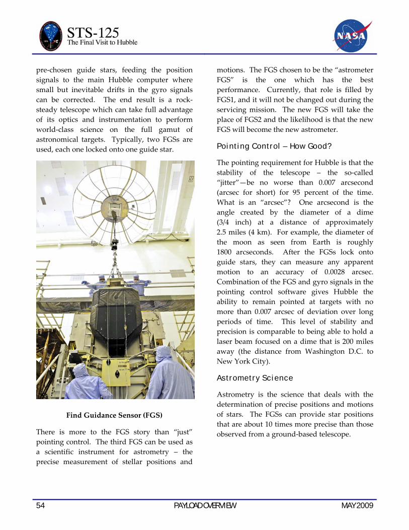
54 PAYLOAD OVERVIEW MAY 2009
pre-chosen guide stars, feeding the position signals to the main Hubble computer where small but inevitable drifts in the gyro signals can be corrected. The end result is a rock-steady telescope which can take full advantage of its optics and instrumentation to perform world-class science on the full gamut of astronomical targets. Typically, two FGSs are used, each one locked onto one guide star.
Find Guidance Sensor (FGS)
There is more to the FGS story than “just” pointing control. The third FGS can be used as a scientific instrument for astrometry – the precise measurement of stellar positions and
motions. The FGS chosen to be the “astrometer FGS” is the one which has the best performance. Currently, that role is filled by FGS1, and it will not be changed out during the servicing mission. The new FGS will take the place of FGS2 and the likelihood is that the new FGS will become the new astrometer.
Pointing Control – How Good?
The pointing requirement for Hubble is that the stability of the telescope – the so-called “jitter”—be no worse than 0.007 arcsecond (arcsec for short) for 95 percent of the time. What is an “arcsec”? One arcsecond is the angle created by the diameter of a dime (3/4 inch) at a distance of approximately 2.5 miles (4 km). For example, the diameter of the moon as seen from Earth is roughly 1800 arcseconds. After the FGSs lock onto guide stars, they can measure any apparent motion to an accuracy of 0.0028 arcsec. Combination of the FGS and gyro signals in the pointing control software gives Hubble the ability to remain pointed at targets with no more than 0.007 arcsec of deviation over long periods of time. This level of stability and precision is comparable to being able to hold a laser beam focused on a dime that is 200 miles away (the distance from Washington D.C. to New York City).
Astrometry Science
Astrometry is the science that deals with the determination of precise positions and motions of stars. The FGSs can provide star positions that are about 10 times more precise than those observed from a ground-based telescope.

MAY 2009 PAYLOAD OVERVIEW 55
When used for astrometric science the FGSs will let Hubble:
• Search for wobbles in the motion of nearby stars that could be indicative of planetary companions.
• Determine if certain stars really are double stars.
• Measure the angular diameter of stars, galaxies and other celestial objects.
• Refine the positions, distances and energy output of stars.
• Help determine the true distance scale for the universe.
Servicing
The FGS that was returned on SM3A has been refurbished and upgraded for re-use on Hubble’s Servicing Mission 4. This refurbished unit has an enhanced in-orbit alignment capability over the original FGS design.
FGS PHYSICAL CHARACTERISTICS
Size 5.5 x 4 x 2 feet Weight 478 pounds
Power 19 Watts
NEW OUTER BLANKET LAYERS (NOBLS)
During the Hubble Space Telescope Second Servicing Mission in 1997 and subsequent missions, astronauts observed damage to some of the telescope’s thermal insulation. Years of exposure to the harsh environment of space had taken a toll on Hubble’s protective multi-layer insulation, and some areas were torn or broken. This multi-layer insulation protects the observatory from the severe and rapid temperature changes it experiences as it moves
through its 97-minute orbit from very hot sun to very cold night.
Protecting and Maintaining Normal Operating Temperatures
The New Outer Blanket Layer (NOBL) covers protect Hubble’s external blankets. They prevent further degradation of the insulation and maintain normal operating temperatures of Hubble’s electronic equipment. Each NOBL has been tested to ensure that it can withstand exposure to: charged particles, X-rays, ultraviolet radiation, and thermal cycling for at least 10 years.
The covers are made of specially coated stainless steel foil which is trimmed to fit each particular equipment bay door that is covered. Each cover is supported by a steel picture-frame structure. Expanding plugs, like common kitchen bottle stoppers, fit into door vent holes to allow quick installation by the spacewalking astronauts.
During Servicing Mission 3A in 1999, astronauts installed three NOBLs on damaged areas. During Servicing Mission 3B in March 2002, a fourth NOBL was installed. Up to three additional NOBL panels will be installed during Servicing Mission 4.
RESTORE ACTIVITIES
REPAIR OF ADVANCED CAMERA FOR SURVEYS
The Advanced Camera for Surveys (ACS) was installed on the Hubble Space Telescope during Servicing Mission 3B in 2002. An electronics failure in January 2007 rendered inoperable the two most-used science channels, and ACS currently runs on one remaining channel. A repair attempt by spacewalking astronauts
56 PAYLOAD OVERVIEW MAY 2009
during Servicing Mission 4 will specifically target restoration of the Wide Field Channel (WFC), the workhorse responsible for 70 percent of the pre-2007 ACS science. The goal, however, is to restore both of the inoperable channels while preserving the third, bringing ACS back to full capability.
Instrument and Repair Overview
ACS was primarily designed to survey large areas of the sky at visible and red wavelengths with 10 times greater efficiency than the earlier premier Hubble camera, the Wide Field Planetary Camera 2 (WFPC2). For five years ACS brilliantly lived up to that promise. Many of the most extraordinary images from Hubble were taken with the ACS/ WFC, most famously perhaps the Hubble Ultra Deep Field, still the deepest, most detailed look into the early universe after galaxies had begun to form. The High Resolution Channel (HRC) provided higher angular resolution over a smaller field-of-view, and it included an option for corona-graphic imaging of faint objects around bright stars. The Solar-Blind Channel (SBC) – the one channel still working—was designed to provide small field-of-view imaging in the far ultraviolet region of the spectrum. Following its installation on Hubble, the ACS became the observatory’s most heavily used instrument.
To increase scientific longevity, Hubble instruments are designed to be electrically redundant. The January 2007 failure was actually on electronics “Side 2,” an earlier power supply failure in 2006 having made Side 1 unable to operate WFC and HRC. With the high currents it generated, the Side 2 short circuit was very energetic, but it was not precisely localized to a particular component part. The failure took down operations on all three science channels, and the SBC is currently
running on the portions of Side 1 that were unaffected by the 2006 event. Because of the certainty of greater damage to Side 2 and the more precise knowledge of what happened on Side 1, the Hubble Program settled on Side 1 as offering the greater chance for successful repair.
To restore WFC and HRC, power not now available must somehow be provided to their control electronics. Because neither the partially failed Side 1 power supply nor the cabling which connects it to the control electronics is accessible to the astronauts, direct repair is not possible and a two-pronged alternative approach must be taken. The electronics boards that control WFC are accessible and will be replaced with modified boards. Second, a completely new power supply will be mounted to a handrail outside of ACS and mated to the new electronics with external cabling.
HRC also has accessible electronics boards, but there is not enough EVA time available on the mission to allow replacement of the boards for both the WFC and HRC channels. However, inside ACS is wiring connecting the WFC and HRC electronics boxes which is believed to be intact, and by driving the new WFC electronics boards with the external power supply, it is expected, but not guaranteed, that the HRC will be “back-powered” and become operable.
Astronauts will access the WFC electronics by removing a small panel outside the instrument. They must remove and replace four boards, for which special tools have been developed. To reduce repair time, a cartridge will hold the replacement boards and be mated into the electronics box with a single action. The new boards in their cartridge must be smaller than the originals. The new design incorporates a specialized integrated circuit called an
MAY 2009 PAYLOAD OVERVIEW 57
Application-Specific Integrated Circuit, or ASIC, that enables an entire circuit board’s worth of electronics to be condensed into a very small package. A great strength of this approach is that the ASIC can be completely re-programmed by commands from controllers on the ground, and the WFC can be fine-tuned for best performance. The ASIC design is the same as the one already developed and tested for the James Webb Space Telescope (to be launched in 2013), although the electronics packaging is different because of the dissimilar environments for the two missions.
The Instrument
WFC and HRC have Charge Coupled Devices (CCDs) for detectors. WFC has a 4k x 4k pixel format created by two adjacent 2k x 4k devices. The CCDs were optimized for sensitivity in the red region of the spectrum, and spectral coverage extends from about 3500 Angstroms (A) in the blue, up beyond the visible-red to 1.1 microns (11,000A). The field of view is 202 x 202 arcseconds (arcsec).
HRC’s CCD has smaller pixels in a 1k x 1k format. With sensitivity from 1700A to 1.1 microns, HRC has greater spectral range than WFC. The field of view is 26 x 29 arcsec. Within HRC is a coronagraph that can place either of two opaque disks in front of stars so that nearby faint objects, e.g., brown dwarf companions, giant planets, or dusty disks, can be shielded from the stellar glare and be seen.
In the far ultraviolet, SBC uses a Multi-Anode Microchannel Array (MAMA), also used by the Space Telescope Imaging Spectrograph (STIS) on Hubble. MAMAs are insensitive to visible light and have essentially no electronic noise. SBC has a 1k x 1k pixel format, a field of 31 x 35 arcsec, and sensitivity from 1150 to
1700A. All the detector channels employ selectable filters mounted on rotating filter wheels to transmit the desired color of light to the detector for any particular image.
The restored ACS will complement the new WFC3, a bonus provided by the decision that WFC3 would not simply be a “carbon copy” of ACS but would have its own unique capabilities. The choice to optimize ACS performance in visible-to-red light was ideal for surveying red-shifted galaxies and clusters of galaxies at moderate-to-large distances across the universe. Although its sensitivity in visible-red wavelengths is good, WFC3’s CCD channel is optimized for high sensitivity, wide field-of-view, and high spatial resolution in the ultraviolet, a first for Hubble. A second WFC3 channel provides the high-sensitivity, wide-field imaging in the near-infrared (above 1 micron) which is unavailable on ACS and which greatly surpasses the smaller-field Near Infrared Camera and Multi-Object Spectrograph (NICMOS). ACS and WFC3 together enable the “best of all worlds” for astronomers, providing superb wide-field imaging over a huge range of wavelengths.
Scientific Future of ACS
Many scientific programs originally planned for ACS can be continued with WFC3. However, there are especially important areas for which the teaming of a restored ACS and WFC3 would be especially well-suited, two examples being:
• Dark Energy – The nature of Dark Energy, the mysterious “repulsive gravity” that causes accelerating expansion of the local universe, is one of the most compelling problems in contemporary physics. Dark Energy can be probed with Hubble through

58 PAYLOAD OVERVIEW MAY 2009
observations of Type Ia supernovae, which because of their well-understood intrinsic brightness can be used to trace the expansion history of the universe over a sizable fraction of cosmic time. The more SN Ia’s that can be observed, the more precise becomes our understanding of Dark Energy’s strength and time variability (if any). ACS and WFC3 working in parallel would detect and make follow-up observations substantially more rapidly than WFC3 alone. ACS has already proven its remarkable capabilities in the efficient detection of distant supernovae.
• Dark Matter – Approximately 24 percent of the universe’s matter and energy budget consists of a not-understood form of matter that neither emits nor absorbs light (hence is “dark”), and can only be detected by its gravitational influence on normal matter and light. By taking many images over large areas of sky (“tiling”), ACS has shown that the slight distortion of distant galaxy shapes produced by dark matter through “gravitational lensing” can be used to measure the amount and distribution of the dark matter in the universe. ACS and WFC3 working together would be a formidable team in this crucial area that, in spite of ACS’s tremendous work to-date, is still in its infancy.
REPAIR OF SPACE TELESCOPE IMAGING SPECTROGRAPH
The Space Telescope Imaging Spectrograph (STIS) was installed on the Hubble Space Telescope during Servicing Mission 2 in 1997. STIS stopped functioning in August 2004 due to a power supply failure, and is currently in
“safe mode” pending a repair attempt during Servicing Mission 4.
Instrument and Repair Overview
STIS is a highly versatile instrument with a proven track record. Its main function is spectroscopy – the separation of light into its component colors (or wavelengths) to reveal information about the chemical content, temperature and motion of planets, comets, stars, interstellar gas and galaxies. A key feature of STIS is its ability to produce the spectrum of spatially extended objects, such as galaxies, covering many points across the image simultaneously. This is why it is called an “imaging spectrograph.” The instrument is sensitive to a wide range of wavelengths of light, spanning from the vacuum ultraviolet through the optical to the near infrared, Although spectrographs generally do not produce beautiful images like Hubble’s cameras, the data they provide are absolutely essential to understanding the physical properties of the material universe – they put the “physics” in astrophysics. At the time when operations suspended in August of 2004, STIS science constituted about 30 percent of the Hubble observing program.
To repair STIS, astronauts will perform a spacewalk to replace a low voltage power supply board which contains a failed power converter. The repair is straightforward but requires diligence, and Hubble engineers have designed special tools for the job. If successful, the repair effort will restore one of two fully redundant electronic chains (or “sides”) of the instrument. Both were unusable after August 2004.
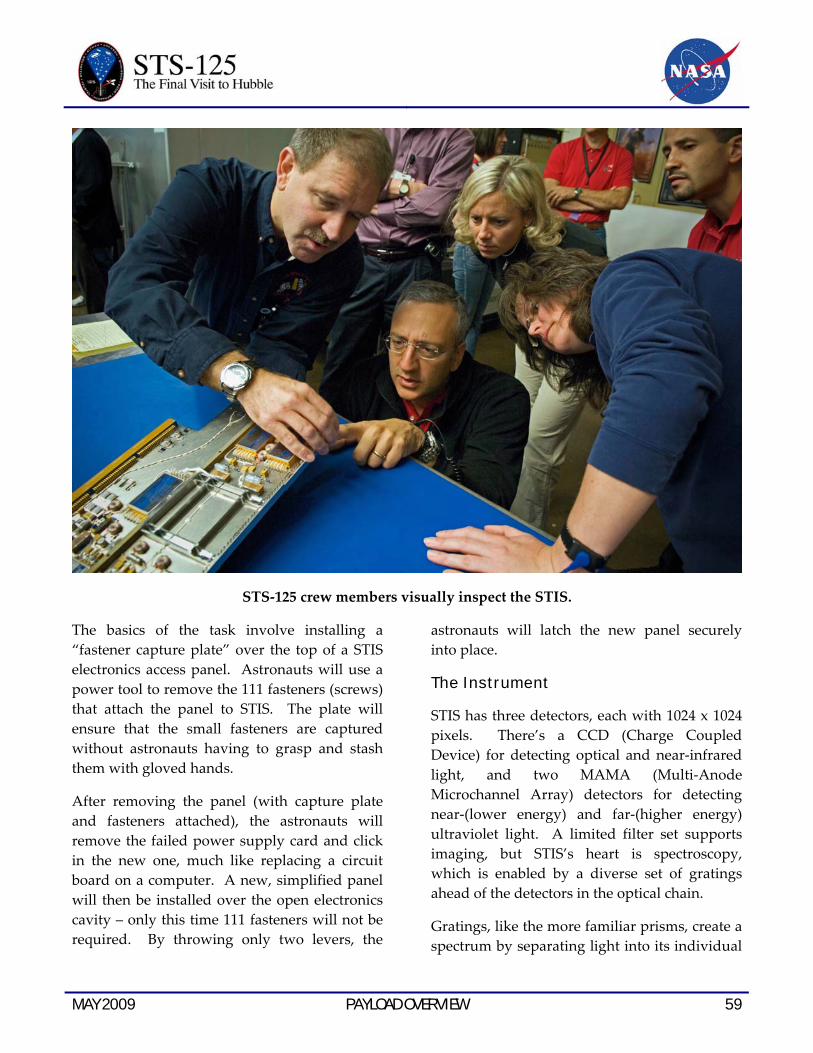
MAY 2009 PAYLOAD OVERVIEW 59
STS-125 crew members visually inspect the STIS.
The basics of the task involve installing a “fastener capture plate” over the top of a STIS electronics access panel. Astronauts will use a power tool to remove the 111 fasteners (screws) that attach the panel to STIS. The plate will ensure that the small fasteners are captured without astronauts having to grasp and stash them with gloved hands.
After removing the panel (with capture plate and fasteners attached), the astronauts will remove the failed power supply card and click in the new one, much like replacing a circuit board on a computer. A new, simplified panel will then be installed over the open electronics cavity – only this time 111 fasteners will not be required. By throwing only two levers, the
astronauts will latch the new panel securely into place.
The Instrument
STIS has three detectors, each with 1024 x 1024 pixels. There’s a CCD (Charge Coupled Device) for detecting optical and near-infrared light, and two MAMA (Multi-Anode Microchannel Array) detectors for detecting near-(lower energy) and far-(higher energy) ultraviolet light. A limited filter set supports imaging, but STIS’s heart is spectroscopy, which is enabled by a diverse set of gratings ahead of the detectors in the optical chain.
Gratings, like the more familiar prisms, create a spectrum by separating light into its individual

60 PAYLOAD OVERVIEW MAY 2009
wavelength components. Close examination of the amount of light at each wavelength reveals the presence of absorption and emission lines, which are the “fingerprints” of the chemical composition and physical and dynamical states of stars and gas. The astronomer has a wide choice of gratings according to her/his needs for wavelength coverage and spectral resolution.
A unique feature of STIS is that by having light enter a long, narrow slit before reaching the gratings, a separate spectrum can be recorded simultaneously along each of the 1024 “pixel rows” of the detector. By orienting the long slit, for example, across the nucleus of a galaxy, one can efficiently measure how fast the galaxy is rotating at different distances away from its center.
In many respects STIS complements the new Cosmic Origins Spectrograph (COS) to be mounted on Hubble during the servicing mission. COS was designed with one primary purpose, to easily measure exceedingly faint levels of ultraviolet light emanating from very faint cosmic point sources, e.g., faint stars in our own galaxy and quasars far out across the universe. A repaired STIS will efficiently provide spatially resolved spectra of extended objects, spectra at visible and near-infrared wavelengths, very high (sharply defined) spectral resolution and measurements of the way some spectra vary with time – capabilities for which COS was not designed.
Cosmic Origins Spectrograph (COS)
Scientific Future of STIS
Although it performed brilliantly for 7.5 years before suspending operations in 2004, the scientific potential of STIS is far from exhausted. Working side by side, the COS-STIS tandem will offer a full set of spectro-scopic tools for the astronomer. Each instrument partly backs up the other; each offers something the other doesn’t. Some glimpses into STIS’s scientific past offer a glimpse of future endeavors:
• Black Holes – The light emitted by stars and gas orbiting around a black hole appears redder when moving away from us (redshift), and bluer when coming toward us (blueshift). By looking for this telltale Doppler shift, STIS has uncovered and weighed several dozen supermassive black holes at the cores of galaxies, but there is still much work to be done. To nail down the relationship between black hole mass and the properties of the host galaxies, more observations of both high- and low-mass black holes are needed.
• Galaxies – STIS can simultaneously record the spectra of up to 50 spatially distinct locations within an extended object such as a galaxy. This is a crucial tool for the

MAY 2009 PAYLOAD OVERVIEW 61
STS-125 mission specialist Mike Massimino conducts work on the STIS.
efficient mapping of a complex environment. As an example, long-slit STIS spectra of young star clusters in the merging “Antennae Galaxies” revealed their ages, chemical compositions and velocities, and the slit was crucial for subtraction of the “sky background.” More STIS observations of such merging galaxies are important to our understanding of what happens to galaxies when they collide with each other.
• Stars – At the time it ceased operating, STIS was being used in a continuing survey of the gas and dust blown off by the highly unstable, massive binary star, eta Carinae, which is located in our own galactic neighborhood, about 8000 light years from the sun. Astronomers expect that some day, perhaps a few thousand years from now, eta Carinae may explode as a supernova. STIS provides a unique opportunity to probe the details of the final stages of life of such a star before its cataclysmic death.
62 PAYLOAD OVERVIEW MAY 2009
• Planets Around Other Stars – STIS spectra of the transiting star-planet system HD209458 resulted in transit light curves so precise that starlight absorption by the planet’s atmosphere was detected, allowing the identification of several planetary atmospheric constituents, including hydrogen, oxygen and sodium – a first. More examples of bright transiting systems are now known and available for study with a repaired STIS, and the promise of yet more systems being discovered is high.
The STIS Team: NASA Goddard Space Flight Center led the original STIS development and is leading the repair effort. The principal investigator is Dr. Bruce E. Woodgate of NASA Goddard, and Ball Aerospace Systems Group is the prime contractor. The Space Telescope Science Institute in Baltimore, Md., manages STIS.
RENEW ACTIVITIES
Wide Field Camera 3
After astronauts install the Wide Field Camera 3 (WFC3) during the servicing mission, it will continue the pioneering tradition of previous Hubble cameras, but with critical improvements to take the telescope on a new voyage of discovery. Together with the new Cosmic Origins Spectrograph (COS), WFC3 will lead the way to many more exciting scientific discoveries.
Instrument Overview
WFC3 will study a diverse range of objects and phenomena, from young and extremely distant galaxies, to much more nearby stellar systems, to objects within our very own solar system. Its
key feature is its ability to span the electromagnetic spectrum from the ultraviolet (UV, the kind of radiation that causes sunburn), through visible/optical light (what human eyes can detect), and into the near infrared (NIR, the kind of radiation seen with night-vision goggles). WFC3 extends Hubble’s capability not only by seeing deeper into the universe but also by providing wide-field imagery in all three regions of the spectrum – UV-Visible-NIR.
It is this wide-field “panchromatic” coverage of light that makes WFC3 so unique. As an example, WFC3 will observe young, hot stars (glowing predominantly in UV) and older, cooler stars (glowing predominantly in the red and NIR) in the same galaxy.
Should astronauts successfully repair the Advanced Camera for Surveys (ACS), it will complement the WFC3. ACS was optimized for wide-field imagery in the visible, and although it can detect UV light the field of view is small. ACS also was not designed to go very far into the NIR, a function currently served by the modest field-of-view NICMOS instrument. WFC3 will produce excellent images in the visible, but most importantly it will “fill in” the missing wide-field coverage in the UV and NIR.
In short, WFC3 by itself, and especially WFC3 and ACS working in tandem, will create a new golden age of imaging for Hubble. Moreover, WFC3’s ability to create crisp images of infrared sources makes it a steppingstone to NASA’s James Webb Space Telescope, Hubble’s successor planned for launch next decade. The first stars and galaxies to form in the universe are so old and distant that their light is now relegated to infrared wavelengths. WFC3 could bring us at last to this era.

MAY 2009 PAYLOAD OVERVIEW 63
The Wide Field Camera 3 is inspected and readied for flight aboard STS-125.
The Instrument
The WFC3 is configured as a two-channel instrument. Its wide-wavelength coverage with high efficiency is made possible by this dual-channel design using two detector technologies. The incoming light beam from the Hubble telescope is directed into WFC3 using a pick-off mirror, and is directed to either the Ultraviolet-Visible (UVIS) channel or the Near-Infrared (NIR) channel. The light-sensing detectors in both channels are solid-state devices. For the UVIS channel a large format Charge Coupled Device (CCD), similar to
those found in digital cameras, is used. In the NIR detector the crystalline photosensitive surface is composed of mercury, cadmium and tellurium (HgCdTe).
The high sensitivity to light of the 16 megapixel UVIS CCD, combined with a wide field of view (160x160 arcseconds), yields about a 35-times improvement in discovery power versus Hubble’s current most sensitive ultraviolet imager, the ACS High Resolution Channel. The NIR channel’s HgCdTe detector is a highly advanced and larger (one megapixel) version of the 65,000 pixel detectors in the current
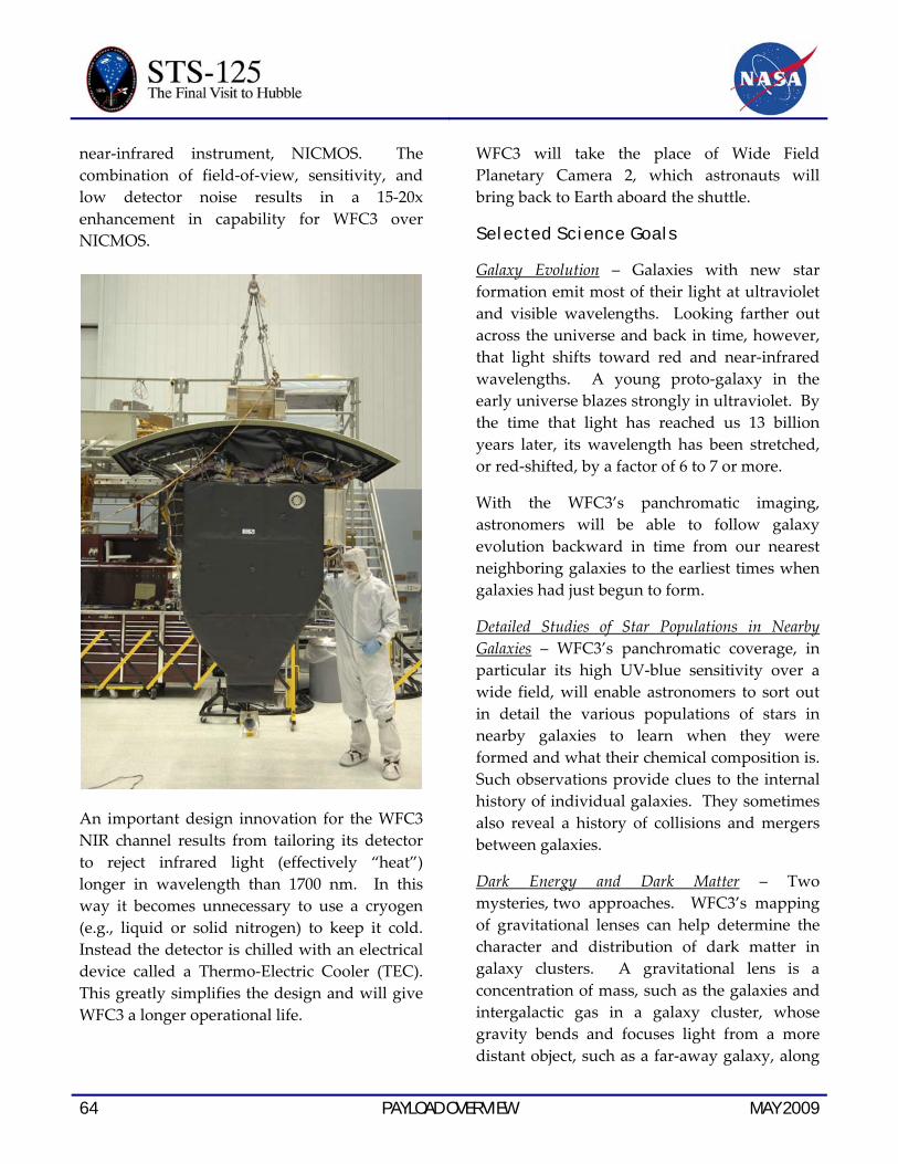
64 PAYLOAD OVERVIEW MAY 2009
near-infrared instrument, NICMOS. The combination of field-of-view, sensitivity, and low detector noise results in a 15-20x enhancement in capability for WFC3 over NICMOS.
An important design innovation for the WFC3 NIR channel results from tailoring its detector to reject infrared light (effectively “heat”) longer in wavelength than 1700 nm. In this way it becomes unnecessary to use a cryogen (e.g., liquid or solid nitrogen) to keep it cold. Instead the detector is chilled with an electrical device called a Thermo-Electric Cooler (TEC). This greatly simplifies the design and will give WFC3 a longer operational life.
WFC3 will take the place of Wide Field Planetary Camera 2, which astronauts will bring back to Earth aboard the shuttle.
Selected Science Goals
Galaxy Evolution – Galaxies with new star formation emit most of their light at ultraviolet and visible wavelengths. Looking farther out across the universe and back in time, however, that light shifts toward red and near-infrared wavelengths. A young proto-galaxy in the early universe blazes strongly in ultraviolet. By the time that light has reached us 13 billion years later, its wavelength has been stretched, or red-shifted, by a factor of 6 to 7 or more.
With the WFC3’s panchromatic imaging, astronomers will be able to follow galaxy evolution backward in time from our nearest neighboring galaxies to the earliest times when galaxies had just begun to form.
Detailed Studies of Star Populations in Nearby Galaxies – WFC3’s panchromatic coverage, in particular its high UV-blue sensitivity over a wide field, will enable astronomers to sort out in detail the various populations of stars in nearby galaxies to learn when they were formed and what their chemical composition is. Such observations provide clues to the internal history of individual galaxies. They sometimes also reveal a history of collisions and mergers between galaxies.
Dark Energy and Dark Matter – Two mysteries, two approaches. WFC3’s mapping of gravitational lenses can help determine the character and distribution of dark matter in galaxy clusters. A gravitational lens is a concentration of mass, such as the galaxies and intergalactic gas in a galaxy cluster, whose gravity bends and focuses light from a more distant object, such as a far-away galaxy, along
MAY 2009 PAYLOAD OVERVIEW 65
our line of sight. This phenomenon was predicted by Einstein’s General Theory of Relativity and is frequently observed in Hubble images. WFC3 plus ACS could conduct systematic searches for Type Ia supernovae to
measure the expansion history of the universe and get a handle on dark energy. The surveys will be 2-3 times more efficient than previous methods using ACS and NICMOS.
WFC3 characteristics UVIS Channel NIR Channel Spectral range (nm) 200-1000 850-1700 Detector type CCD HgCdTe Detector array size (pixels) 4096 x 4096 1024 x 1024 Field of view (arcseconds) 160 x 160 123 x 137 Pixel size (arcsec) 0.04 0.13 Filter complement 62 15 Discovery factor over previous 35x over 15-20x over Hubble instruments ACS/HRC NICMOS
The Hubble Program at Goddard Space Flight Center jointly developed WFC3 with the Space Telescope Science Institute in Baltimore and Ball Aerospace & Technologies Corporation in Boulder. A community-based Science Oversight Committee, led by Prof. Robert O’Connell of the University of Virginia, provided scientific guidance for its development.
COSMIC ORIGINS SPECTROGRAPH
Installing the Cosmic Origins Spectrograph (COS) during the servicing mission will effectively restore spectroscopy to Hubble’s scientific arsenal, and at the same time provide the telescope with unique capabilities. Together with the other new Hubble instrument – the Wide Field Camera 3 (WFC3) – COS will journey toward more ground-breaking scientific discoveries.
Instrument Overview
COS is designed to study the large-scale structure of the universe and how galaxies, stars and planets formed and evolved. It will help determine how elements needed for life such as carbon and iron first formed and how their abundances have increased over the lifetime of the universe.
As a spectrograph, COS won’t capture the majestic visual images that Hubble is known for, but rather it will perform spectroscopy, the science of breaking up light into its individual components. Any object that absorbs or emits light can be studied with a spectrograph to determine its temperature, density, chemical composition and velocity.
A primary science objective for COS is to measure the structure and composition of the ordinary matter that is concentrated in what scientists call the “cosmic web” – long, narrow filaments of galaxies and intergalactic gas separated by huge voids. The cosmic web is
66 PAYLOAD OVERVIEW MAY 2009
shaped by the gravity of the mysterious, underlying cold dark matter, while ordinary matter serves as a luminous tracery of the filaments. COS will use scores of faint distant quasars as “cosmic flashlights,” whose beams of light have passed through the cosmic web. Absorption of this light by material in the web will reveal the characteristic spectral fingerprints of that material. This will allow Hubble observers to deduce its composition and its specific location in space.
Observations like this, covering vast distances across space and back in time, will illuminate both the large-scale structure of the universe and the progressive changes in chemical composition of matter, as the universe has grown older.
The Instrument
COS has two channels, the Far Ultraviolet (FUV) channel covering wavelengths from 115 to 177 nm, and the Near Ultraviolet (NUV) channel, covering 175-300 nm. Ultraviolet light, the type of radiation that causes sunburn, is more energetic than visible, optical light; and “near” UV refers to the part of the UV spectrum closer to the visible, just beyond the color violet.
The light-sensing detectors of both channels are designed around thin micro-channel plates comprising thousands of tiny curved glass tubes, all aligned in the same direction. Simply described, incoming photons of light ultimately induce showers of electrons to be emitted from the walls of these tubes. The electron showers are accelerated, captured, and counted in electronic circuitry immediately behind the micro-channel plates.
A key feature of COS – the one which makes it unique among Hubble spectrographs – is its maximized efficiency, or “throughput.” Each bounce of a light beam off an optical surface within an instrument takes some of the light away from the beam, reducing the throughput. This is a problem that is especially acute in the UV, and the COS FUV channel was designed specifically to minimize the number of light bounces. The incoming FUV beam makes one bounce off a selectable light-dispersing grating, and goes directly to the detector. An additional advantage within COS is the very low level of scattered light produced by its light-dispersing gratings.
If astronauts are able to complete the in-orbit repair of the Space Telescope Imaging Spectrograph (STIS) aboard Hubble, it will serve to complement the COS. The “all purpose” STIS, installed in 1997 during Servicing Mission 2, suffered an electronics failure in 2004 and is currently in safe hold. By design, the COS does not duplicate all of STIS’s capabilities. Possessing more than 30 times the sensitivity of STIS for FUV observations of faint objects such as distant quasars, COS will enable key scientific programs which would not be possible using STIS. On the other hand, COS is best suited to observing point sources of light such as stars and quasars, while STIS has the unique ability to observe the spectrum of light across spatially extended objects such as galaxies and nebulae. Should STIS be repaired, the two spectrographs working in tandem will provide astronomers with a full set of spectroscopic tools for astrophysical research.
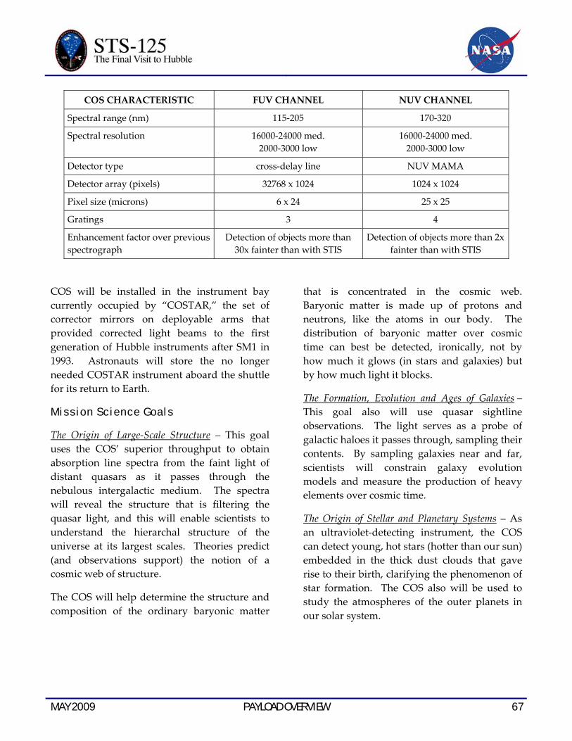
MAY 2009 PAYLOAD OVERVIEW 67
COS CHARACTERISTIC FUV CHANNEL NUV CHANNEL
Spectral range (nm) 115-205 170-320
Spectral resolution 16000-24000 med. 2000-3000 low
16000-24000 med. 2000-3000 low
Detector type cross-delay line NUV MAMA
Detector array (pixels) 32768 x 1024 1024 x 1024
Pixel size (microns) 6 x 24 25 x 25
Gratings 3 4
Enhancement factor over previous spectrograph
Detection of objects more than 30x fainter than with STIS
Detection of objects more than 2x fainter than with STIS
COS will be installed in the instrument bay currently occupied by “COSTAR,” the set of corrector mirrors on deployable arms that provided corrected light beams to the first generation of Hubble instruments after SM1 in 1993. Astronauts will store the no longer needed COSTAR instrument aboard the shuttle for its return to Earth.
Mission Science Goals
The Origin of Large-Scale Structure – This goal uses the COS’ superior throughput to obtain absorption line spectra from the faint light of distant quasars as it passes through the nebulous intergalactic medium. The spectra will reveal the structure that is filtering the quasar light, and this will enable scientists to understand the hierarchal structure of the universe at its largest scales. Theories predict (and observations support) the notion of a cosmic web of structure.
The COS will help determine the structure and composition of the ordinary baryonic matter
that is concentrated in the cosmic web. Baryonic matter is made up of protons and neutrons, like the atoms in our body. The distribution of baryonic matter over cosmic time can best be detected, ironically, not by how much it glows (in stars and galaxies) but by how much light it blocks.
The Formation, Evolution and Ages of Galaxies – This goal also will use quasar sightline observations. The light serves as a probe of galactic haloes it passes through, sampling their contents. By sampling galaxies near and far, scientists will constrain galaxy evolution models and measure the production of heavy elements over cosmic time.
The Origin of Stellar and Planetary Systems – As an ultraviolet-detecting instrument, the COS can detect young, hot stars (hotter than our sun) embedded in the thick dust clouds that gave rise to their birth, clarifying the phenomenon of star formation. The COS also will be used to study the atmospheres of the outer planets in our solar system.

68 PAYLOAD OVERVIEW MAY 2009
This page intentionally left blank.
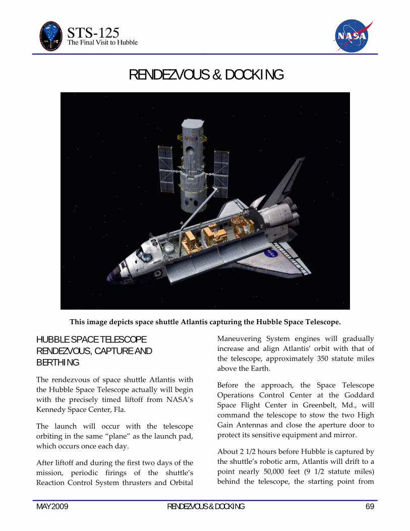
MAY 2009 RENDEZVOUS & DOCKING 69
RENDEZVOUS & DOCKING
This image depicts space shuttle Atlantis capturing the Hubble Space Telescope.
HUBBLE SPACE TELESCOPE RENDEZVOUS, CAPTURE AND BERTHING
The rendezvous of space shuttle Atlantis with the Hubble Space Telescope actually will begin with the precisely timed liftoff from NASA’s Kennedy Space Center, Fla.
The launch will occur with the telescope orbiting in the same “plane” as the launch pad, which occurs once each day.
After liftoff and during the first two days of the mission, periodic firings of the shuttle’s Reaction Control System thrusters and Orbital
Maneuvering System engines will gradually increase and align Atlantis’ orbit with that of the telescope, approximately 350 statute miles above the Earth.
Before the approach, the Space Telescope Operations Control Center at the Goddard Space Flight Center in Greenbelt, Md., will command the telescope to stow the two High Gain Antennas and close the aperture door to protect its sensitive equipment and mirror.
About 2 1/2 hours before Hubble is captured by the shuttle’s robotic arm, Atlantis will drift to a point nearly 50,000 feet (9 1/2 statute miles) behind the telescope, the starting point from

70 RENDEZVOUS & DOCKING MAY 2009
which the final approach to the observatory will begin.
At that point, the crew will oversee a precisely-targeted thruster firing called the Terminal Initiation, or TI burn, that sets the stage for the final phase of the rendezvous.
Atlantis will close the final miles to the telescope during the next orbit of Earth. During that time the shuttle’s rendezvous radar system will begin tracking Hubble by measuring the distance and rate of closure.
During the final approach, the shuttle will have an opportunity to conduct four small mid-course corrections, if required. Simultaneously, Mission Specialist Megan McArthur will maneuver the robotic arm above the payload bay of Atlantis to a position poised to grapple a capture fixture on the telescope.
After the fourth and final mid-course correction burn, the shuttle will be about a half-mile below the telescope. At that point, about an hour before the scheduled docking, Commander Scott Altman will move from his forward seat on the flight deck to the aft flight control station overlooking the payload bay. Looking out of two overhead windows, Altman, assisted by pilot Gregory C. Johnson and Mission Specialist Michael Good, will take over manual control of the approach.
Good will operate a handheld laser range-finding device, aiming it through the shuttle windows at the telescope to provide Altman with supplementary distance and closing rate information. Mission Specialist Andrew Feustel will monitor a laptop computer program displaying real-time navigation information, which will provide Altman with additional cues to aid in controlling his approach.
Altman will slow Atlantis’ approach and fly up toward the telescope, switching the Reaction Control System to a mode known as “low-Z” at a distance of about 1,500 feet. In that mode, jets offset to the direction of the telescope will be fired to continually slow the shuttle's approach, while avoiding any chance of contaminating Hubble with shuttle thruster exhaust, a phenomenon known as “pluming.”
As Atlantis moves within 600 feet, its approach will be slowed to less than a half-mile per hour. As the distance decreases to about 200 feet, Hubble’s ground controllers will send commands to perform a final roll maneuver to position it for capture. The telescope’s solar arrays will remain parallel to Hubble’s optical axis. The shuttle will coast toward the observatory as it closes the final 100 feet, moving at a speed of only a tenth of a foot per second.
Altman will fly Atlantis to within 35 feet of the telescope and hold position, while McArthur, using a view from a camera mounted at the end of the robotic arm to assess alignment, will latch on to the telescope with the robotic arm end effector.
Using views from a camera centered in a structure where the telescope will be berthed, McArthur then will lower Hubble into a special cradle, called the Flight Support System, or FSS, in Atlantis’s payload bay. The telescope will be latched to the high-tech, lazy Susan-type device for the duration of the servicing work. An umbilical adjacent to the rotating FSS will be remotely connected to provide electrical power from Atlantis to the telescope. Then, Altman will position the shuttle to allow Hubble’s solar arrays to gather energy from the sun to fully charge the telescope’s batteries.
7
MAY 2009 RENDEZVOUS & DOCKING 71
During the five servicing spacewalks, the telescope’s support structure can be rotated and pivoted as needed to provide the best available access to various worksites.
HUBBLE SPACE TELESCOPE DEPLOY
On the day before Hubble’s deployment, controllers at Goddard Space Flight Center, Md., will send commands to unfurl the telescope’s high-gain antennas and conduct a final checkout of telemetry with the telescope’s control center.
About three hours before the planned release time, McArthur will power up Atlantis’ robotic arm and latch on to the telescope’s grapple fixture. Altman will maneuver Atlantis to the correct orientation to release the observatory.
The telescope will be switched back to its internal power, its aperture door will be
commanded open to allow starlight to fall upon its optical instruments, and the connection to Atlantis’s power system will be remotely disconnected. Three latches securing Hubble to its support structure will be opened.
After a poll of shuttle and telescope flight controllers, McArthur will unberth Hubble and maneuver it to a point high above the shuttle bay. Atlantis’ steering jets will be turned off to avoid any possible disturbance as McArthur commands the arm to release the telescope’s grapple fixture.
About a minute later, the shuttle thrusters will fire in the Low-Z mode to slowly back Atlantis away. Another jet firing will be performed about a half-hour later to increase Atlantis’ separation rate from the telescope, as the seven crew members bid farewell to Hubble for the final time.

72 RENDEZVOUS & DOCKING MAY 2009
This page intentionally left blank

MAY 2009 SPACEWALKS 73
SPACEWALKS
Astronaut John Grunsfeld, payload commander, peers into the crew cabin of the space shuttle Columbia during the first STS-109 extravehicular activity (EVA-1) on March 4, 2002. Grunsfeld’s
helmet visor displays a mirrored image of the Earth’s hemisphere. The lower portion of the Hubble Space Telescope (HST) can be seen over Grunsfeld’s left shoulder.
The five spacewalks of the STS-125 mission will extend the Hubble Space Telescope’s life and leave it with new equipment that will improve the data that it is able to send back to scientists here on Earth. More than 60 new spacewalk tools were developed for the work to be done on this mission.
Mission Specialists John Grunsfeld, Andrew Feustel, Mike Massimino and Michael Good will spend a combined total of 31 hours and 40 minutes outside of space
shuttle Atlantis on flight days 4, 5, 6, 7 and 8. Grunsfeld, the lead spacewalker for the mission, will suit up for the first, third and fifth spacewalks in a spacesuit marked with solid red stripes. He is an experienced spacewalker with five extravehicular activities, or EVAs, performed in support of Hubble during STS-103 and STS-109.
Massimino, another veteran spacewalker, will wear a spacesuit with a dashed red and white stripe for the mission’s second and fourth
74 SPACEWALKS MAY 2009
spacewalks. He has two Hubble-servicing spacewalks under his belt, performed on STS-109.
Feustel and Good will perform their first spacewalks. Feustel will participate in the first, third and fifth spacewalks and wear an all white spacesuit, while Good will wear a spacesuit with horizontal red stripes for spacewalks two and four.
On each EVA day, the two spacewalkers inside the shuttle will act as the intravehicular officers, or spacewalk choreographers, for those working outside. And Mission Specialist Megan McArthur will work with the spacewalkers from the inside to operate the shuttle’s 50-foot-long robotic arm as needed.
Unlike the preparations for International Space Station-based spacewalks, the spacewalkers for the STS-125 mission will not need to camp out in the shuttle’s airlock overnight to prepare for their time outside the shuttle. Instead, the entire shuttle will be kept at a pressure of 10.2 pounds per square inch beginning on its second day in space, until the day after the last spacewalk. Doing so will decrease the amount of time they’ll need to spend breathing pure oxygen in the hours before they begin their spacewalk, which helps the spacewalkers avoid getting decompression sickness, also known as the bends.
EVA-1
Duration: 6 hours, 30 minutes Crew: Grunsfeld and Feustel
EVA Operations
• Wide Field Planetary Camera 2 removal
• Wide Field Camera 3 installation
• Science Instrument Command and Data Handling Unit replacement
• Latch Over Center Kit installation
• Soft Capture Mechanism installation (get-ahead)
Feustel will begin the first spacewalk of the STS-125 mission by making his way to Wide-field Scientific Instrument Protective Enclosure, in which the telescope’s new equipment was launched, and release some latches. Meanwhile Grunsfeld will set up the foot restraint Feustel (and later in the mission, Good) will use on the shuttle’s robotic arm and install the berthing and positioning system post, which will protect the telescope’s solar arrays from vibration while the spacewalkers are working. He’ll also install a fixture in the cargo bay that will be used to temporarily hold equipment after it is removed.
Feustel will then install a handle on the foot restraint, before climbing on. Inside the station, McArthur will then maneuver him into position for the removal of the Wide Field Planetary Camera 2, or WFPC 2. They’ll replace it with a new wide-field camera that will allow the telescope to take large-scale, clear and detailed photos over a wide range of colors.
Grunsfeld will take advantage of the time it takes Feustel to get into place by installing a protective cover on Hubble’s low-gain antenna. Once that’s done, he’ll join Feustel at the WFPC 2.
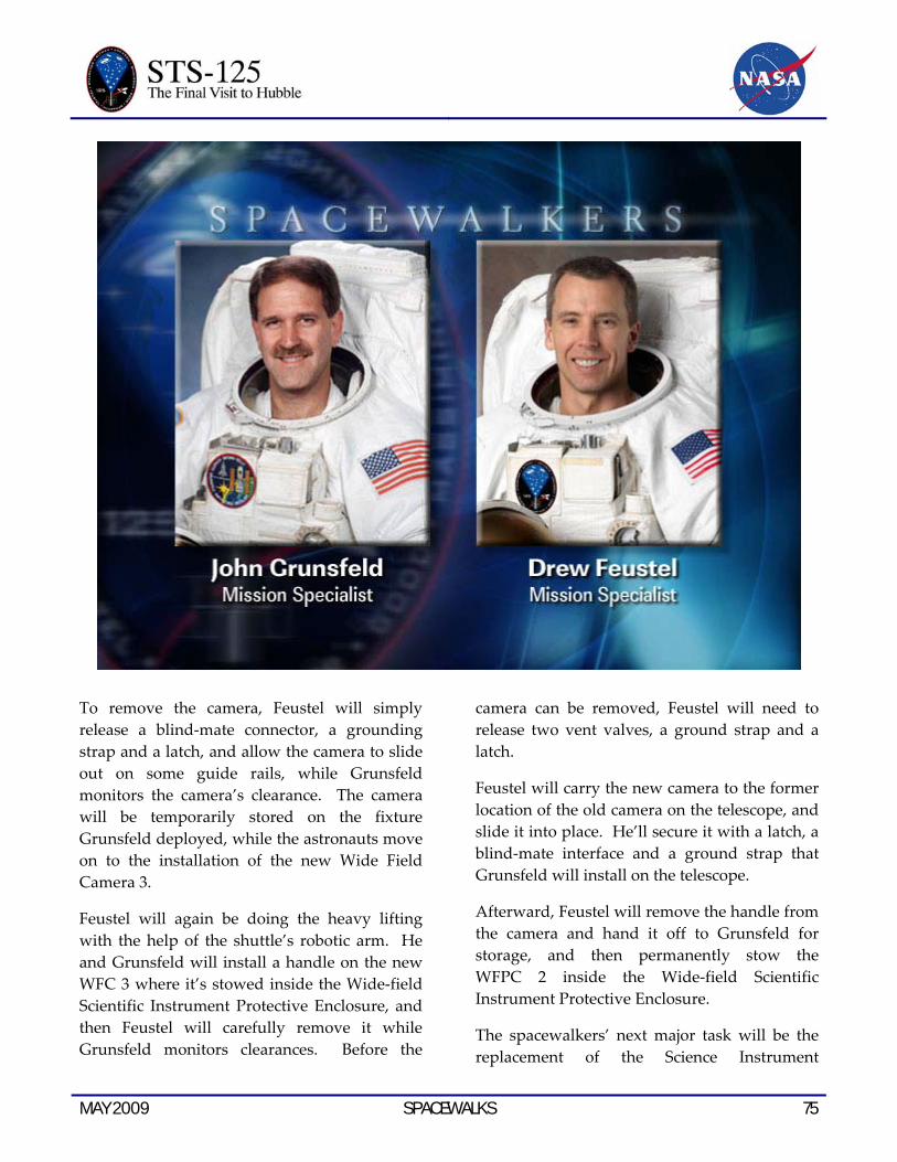
MAY 2009 SPACEWALKS 75
To remove the camera, Feustel will simply release a blind-mate connector, a grounding strap and a latch, and allow the camera to slide out on some guide rails, while Grunsfeld monitors the camera’s clearance. The camera will be temporarily stored on the fixture Grunsfeld deployed, while the astronauts move on to the installation of the new Wide Field Camera 3.
Feustel will again be doing the heavy lifting with the help of the shuttle’s robotic arm. He and Grunsfeld will install a handle on the new WFC 3 where it’s stowed inside the Wide-field Scientific Instrument Protective Enclosure, and then Feustel will carefully remove it while Grunsfeld monitors clearances. Before the
camera can be removed, Feustel will need to release two vent valves, a ground strap and a latch.
Feustel will carry the new camera to the former location of the old camera on the telescope, and slide it into place. He’ll secure it with a latch, a blind-mate interface and a ground strap that Grunsfeld will install on the telescope.
Afterward, Feustel will remove the handle from the camera and hand it off to Grunsfeld for storage, and then permanently stow the WFPC 2 inside the Wide-field Scientific Instrument Protective Enclosure.
The spacewalkers’ next major task will be the replacement of the Science Instrument

76 SPACEWALKS MAY 2009
Command and Data Handling Unit. The computer sends commands to Hubble’s science instruments and formats science data for transmission to the ground.
The computer will be carried to the telescope inside a multi-use lightweight equipment carrier in the shuttle’s cargo bay. Grunsfeld will remove the new computer from the carrier by releasing eight bolts, while Feustel removes the old computer from the telescope by releasing 10 bolts. Feustel will carry the old computer to Grunsfeld at the carrier, where the two will swap. Feustel will then carry the new computer back to the telescope and install it, while Grunsfeld stores the old one inside the carrier.
If time permits, Grunsfeld will then install a soft capture mechanism, which will allow future vehicles to attach to the telescope. The mechanism will be attached to the flight support system – or FSS – that connects the shuttle to the telescope. To install it, Grunsfeld will only need to tighten a single bolt, which will both drive latches to attach it to the telescope and release the latches attaching it to the FSS.
As a get-ahead, Feustel may also go ahead and open the door on the telescope’s Bay 2, where Massimino and Good will be working the following day.
Their final scheduled task for the day will be to install three latch-over-center kits that will allow for faster opening and closing of the telescope doors during the third spacewalk.
EVA-2
Duration: 6 hours, 30 minutes Crew: Good and Massimino
EVA Operations
• Rate Sensor Units replacement
• Bay 2 Battery replacement
For their first spacewalk of the STS-125 mission, Massimino and Good will spend the bulk of their time replacing three rate sensor units. Each unit is part of a rate gyro assembly, which sense vehicle motion and provide rate data for the telescope.
The replacement units will be stored inside a protective enclosure inside the shuttle’s cargo bay. Massimino will open the lid of the enclosure to allow Good, who will be riding the space shuttle’s robotic arm for the spacewalk, to retrieve the first unit and carry it to the telescope. Massimino will also retrieve a gripper tool that Good will use to maneuver the units into place.
At the telescope, Good will retract two fixed head star tracker seals, allowing the doors on the telescope bay that the crew will be working in to open. Once open, Good will move a cross aft shroud harness inside the telescope to make room for the foot restraint Massimino will be using. Massimino will retrieve the foot restraint for Good to install, then Good will help Massimino into it.
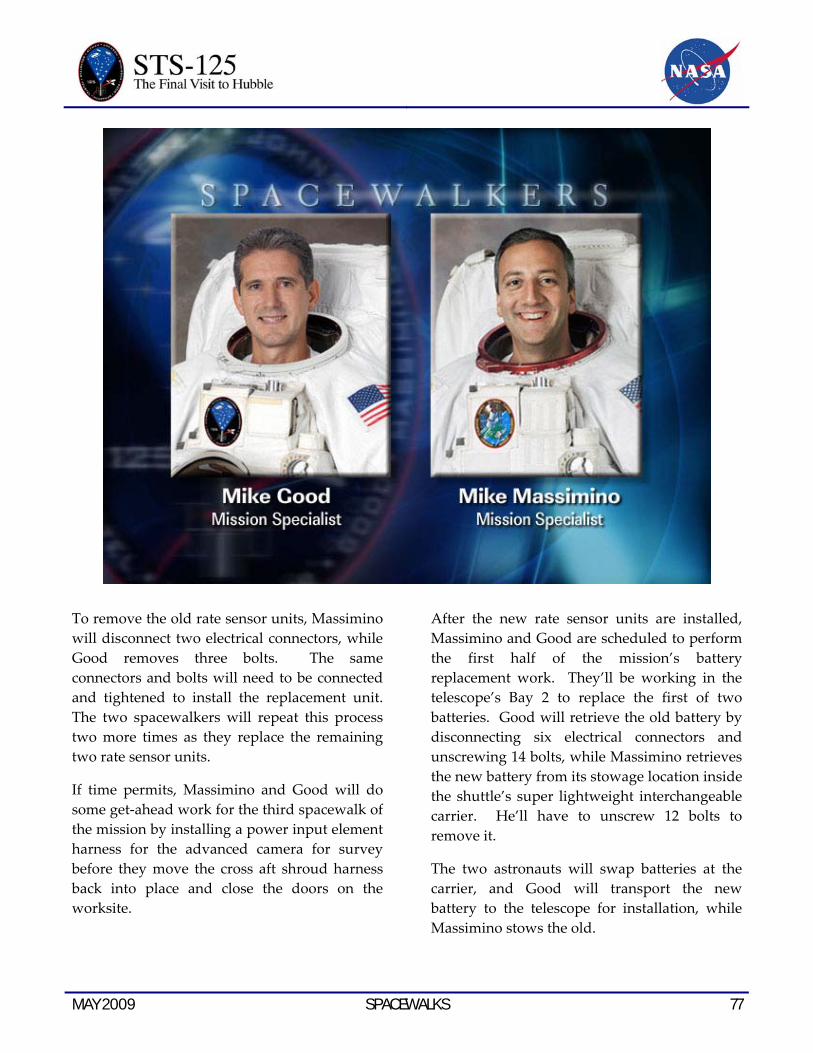
MAY 2009 SPACEWALKS 77
To remove the old rate sensor units, Massimino will disconnect two electrical connectors, while Good removes three bolts. The same connectors and bolts will need to be connected and tightened to install the replacement unit. The two spacewalkers will repeat this process two more times as they replace the remaining two rate sensor units.
If time permits, Massimino and Good will do some get-ahead work for the third spacewalk of the mission by installing a power input element harness for the advanced camera for survey before they move the cross aft shroud harness back into place and close the doors on the worksite.
After the new rate sensor units are installed, Massimino and Good are scheduled to perform the first half of the mission’s battery replacement work. They’ll be working in the telescope’s Bay 2 to replace the first of two batteries. Good will retrieve the old battery by disconnecting six electrical connectors and unscrewing 14 bolts, while Massimino retrieves the new battery from its stowage location inside the shuttle’s super lightweight interchangeable carrier. He’ll have to unscrew 12 bolts to remove it.
The two astronauts will swap batteries at the carrier, and Good will transport the new battery to the telescope for installation, while Massimino stows the old.
78 SPACEWALKS MAY 2009
EVA-3
Duration: 6 hours, 30 minutes Crew: Grunsfeld and Feustel
EVA Operations:
• Corrective Optics Space Telescope Axial Replacement removal
• Cosmic Origins Spectrograph installation
• Advanced Camera for Surveys repair, part one
Grunsfeld and Feustel will be back outside for the third spacewalk of the mission, this time focusing on the installation of the telescope’s new Cosmic Origins Spectrograph, and the first part of the advanced camera for survey repair work.
Grunsfeld will begin by preparing a temporary storage fixture in the shuttle’s cargo bay, while Feustel opens the doors of the telescope bay he and Grunsfeld will be working in. Once everything is ready, Grunsfeld will get the Corrective Optics Space Telescope Axial Replacement – or COSTAR – ready for removal by unhooking four connectors, disconnecting one ground strap and unscrewing two latches. Feustel, again on the shuttle’s robotic arm, will actually remove the equipment and attach it to the temporary storage fixture Grunsfeld prepared.
Both crew members will then move to the protective enclosure that the new Cosmic Origins Spectrograph was launched in and work together to remove it. They will need to disconnect a ground strap, disengage locks and release latches before Feustel will be able to remove the equipment from the carrier and
make his way via robotic arm back to the telescope for its installation.
Feustel will maneuver the equipment into place and engage its two latches. Grunsfeld will then hook up four connectors and a ground strap. Following that installation, the only thing left to do on the tasks will be to store the COSTAR in the protective enclosure that previously housed the spectrograph.
Once that’s done, Grunsfeld and Feustel will begin work on the Advanced Camera for Surveys repair, which may be finished later in the mission if time permits or the Space Telescope Imaging Spectrograph repair on the fourth spacewalk is not successful. In that case, the rest of the Advanced Camera for Surveys work would be added to the fifth spacewalk, replacing the Fine Guidance Sensor work.
For this spacewalk, Grunsfeld and Feustel will spend about two hours and 10 minutes working on the camera and remove two of the four electronics cards that need to be replaced. Grunsfeld’s first task will be to install four guide studs that will be used later to install tools. Feustel will assist him with that job, and then the two will work together to remove a grid. To do so, Grunsfeld will fit a grid cutter over the grid. Tightening the 12 bolts on the grid cutter will cause a blade to cut off the 12 legs of the grid. The grid cutter will also trap the pieces of the grid, so that the spacewalkers don’t have to handle the sharp edges created by cutting the grid off.
That will give them access to a cover plate, which is the next thing Grunsfeld and Feustel will need to remove. This will require Grunsfeld to unscrew 32 fasteners. Grunsfeld will first loosen all the fasteners, and then, to ensure that none of those fasteners are lost, he’ll
MAY 2009 SPACEWALKS 79
install a fastener capture plate over the cover plate before he releases the fasteners. The fastener capture plate will then be removed along with the cover plate.
With that, Grunsfeld will finally be able to access the electronics cards. Feustel will retrieve and hand to him a piece of equipment called a “wishbone” that will be used to mount the tool that will be used to extract the electronic cards from the camera. Feustel also will retrieve that tool for Grunsfeld, as well as the protective storage carrier that Grunsfeld will put each card into as it is removed. To actually remove the card, Grunsfeld will use a card extraction tool that has a jaw to grip the card, which Grunsfeld tightens by tightening bolts, and an elevator block that removes the card when Grunsfeld tightens a different bolt.
EVA-4
Duration: 6 hours, 30 minutes Crew: Massimino and Good
EVA Operations:
• Space Telescope Imaging Spectrograph repair
• New Outer Layer Blanket 8 installation
The bulk of Massimino and Good’s second spacewalk will be spent repairing the telescope’s Space Telescope Imaging Spectrograph – a task that has been compared to brain surgery. To access the electronics card the spacewalkers intend to replace, they’ll need to remove a cover plate. However, there are several obstacles to doing so. First Massimino will need to remove a clamp from the upper left corner of the cover plate. Then he’ll need to remove a handrail. Both of these tasks require special tools to catch the fasteners currently
holding those pieces in place. The clamp removal tool fits over the fasteners of the clamp and catches them as they’re released; the handrail removal tool does the same over the fasteners of the handrail.
The cover plate itself has 111 fasteners that need to be unscrewed. To ensure that none of those small pieces float away, another fastener capture plate will be installed. But to install the fastener capture plate, Massimino must first install guide studs that will be used to mount the plate onto the instrument. To install the guide studs, Massimino will have to release four fasteners without losing the fasteners or their bits. For that job, he’ll use the retainer installation bit caddy, which uses a retaining ring to go around the head of the fasteners and behind it to trap the washer. Then four fasteners can be removed with a fastener extraction bit, and their washers will stay in place to be removed by a washer extraction tool.
That will leave a place for the guide studs to be installed, allowing for the installation of the fastener capture plate. Once it’s in place, Massimino will be able to unscrew the remaining 107 fasteners and washers safely, and – after Good has cut four wires – remove the cover plate. With it out of the way, Massimino will be able to finally access the electronics card that he and Good will replace.
To actually remove the old card, Massimino will use a card extraction tool, just as Grunsfeld did during the third spacewalk. He’ll then store it in a transport case, detach the extraction tool and use the tool to unpack and install the new card. He’ll also install the new card’s simpler cover, which only requires him to engage two locking pins.

80 SPACEWALKS MAY 2009
Once the new card is installed, Massimino and Good will wrap up their last spacewalk by installing one of two new protective thermal insulation panels – called New Outer Layer Blankets – delivered by space shuttle Atlantis. This insulation will be installed on the telescope’s bay 8 door, and Good will start the work by first removing the existing insulation in that area, including a temporary patch installed during the second Hubble servicing mission. This task will involve removing seven clips and unhooking a wire loop holding the patch in place, and cutting two ground wires to release the original insulation.
The new insulation will be installed using four latches and pressure-activated adhesive that Good will activate by pressing a roller tool against its surface.
EVA-5
Duration: 5 hours, 45 minutes Crew: Grunsfeld and Feustel
EVA Operations:
• Bay 3 Battery replacement
• Fine Guidance Sensor replacement
• New Outer Layer Blanket 5 installation
For the final spacewalk of the mission, Grunsfeld and Feustel will be finishing both the battery replacement and New Outer Layer Blanket installation tasks, following the same procedures as those of the work on the second and fourth spacewalks.
Between those two jobs, however, they’ll also be replacing the telescope’s fine guidance sensor. To remove the old sensor, Grunsfeld and Feustel will work together to unhook nine connectors. Then Grunsfeld – who will be riding the shuttle’s robotic arm for this spacewalk – will release one latch and install a handle on the equipment that he’ll use to carefully lift the sensor out of the telescope. He’ll carry it to a protective enclosure inside the shuttle’s cargo bay, where Feustel will be waiting to assist him in storing it and removing the new sensor.
Grunsfeld will carry the new sensor back to the worksite, slide it into place and engage its one latch. Then he’ll work with Feustel to hook up its nine connectors.
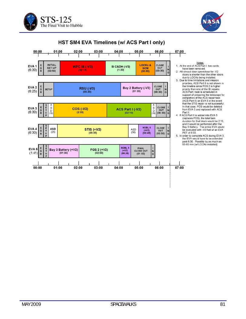
MAY 2009 SPACEWALKS 81

82 SPACEWALKS MAY 2009
This page intentionally blank
MAY 2009 SM4 FACILITIES 83
SM4 FACILITIES
HUBBLE SERVICING MISSION FACILITIES
NASA GODDARD
Space Telescope Operations Control Center (STOCC)
The Hubble Space Telescope is kept under a watchful eye by a dedicated team of professionals at NASA Goddard Space Flight Center’s Space Telescope Operations Control Center, or STOCC.
This group is called the Flight Operations Team (FOT) and is comprised of Hubble engineers and managers who work seven days a week, 365 days a year, constantly monitoring the telescope’s operations.
The STOCC consists of three conjoined rooms:
• In the Mission Operations Room the FOT closely monitors the telescope’s health and safety, as well as controlling flight operations. Some of the tasks they perform include in-depth subsystem analysis, simulated subsystem tests, integrating new databases, and validating new ground software and updates to flight software.
• The Mission Support Room supports nominal Hubble operations through integrated testing for ground systems software updates and engineering activities by providing off-line mission planning functions, data processing and integrated testing.
• Shortly before the Hubble servicing mission in 2009, additional engineers from the subsystems engineering group will be called upon to staff the Servicing Mission Operations Room. This Servicing Mission Operations Team (SMOT) will work in two 12-hour shifts, supporting the preparation, test and simulation for the fifth and final shuttle mission to the famed telescope.
Preparing Hubble for Servicing
Just as NASA astronauts train extensively for each shuttle mission, so do the SMOT and FOT engineers. Their highly choreographed efforts and expertise help ensure the servicing mission goes as planned.
A few hours after the shuttle Atlantis lifts off from Kennedy Space Center, the FOT will prepare the telescope for servicing by placing its science instruments into “safe hold.” During this time, engineers will track Hubble and downlink necessary engineering data.
About 28 hours into the servicing mission, the team will command Hubble to close its aperture door to protect its ultra-sensitive optics. Then the team will send commands to the telescope so it obtains the required rendezvous attitude (for grappling by the shuttle arm), stows, or retracts, its high gain antennas, and repositions its solar arrays to enable the shuttle arm to grapple the telescope.
The astronauts will then secure the telescope to the shuttle’s Flight Support System, which will allow them to reach all the instruments and components slated for repair or replacement.

84 SM4 FACILITIES MAY 2009
Hubble’s internal power will be transferred to the shuttle during servicing.
Testing Hubble during Servicing
During the servicing mission, the SMOT engineers will perform aliveness and functional tests to ensure each instrument and component has power and operates as it should. While the astronauts sleep, this same team will conduct additional functional tests on each installed component to determine if the astronauts need to perform additional work.
After all servicing tasks are completed, Hubble’s newly installed battery packs will be charged to full capacity. The shuttle supplied power feed will be disconnected and Hubble will operate under its own internal power.
The FOT engineers will send commands to Hubble to open its aperture door and the telescope will be released. Additional commands will be sent to deploy Hubble’s high gain antennas and after orbital verification is completed, Hubble will be recommissioned for future science observations.
Scheduling Science Observations
The Space Telescope Science Institute in Baltimore, Md., annually solicits Hubble science research proposals from the worldwide astronomical community and competitively selects the most compelling science observations to place on Hubble’s science observing schedule.
The FOT engineers upload these approved observing schedules to the telescope via a network interface to NASA’s White Sands Complex in New Mexico, which then transmits to NASA’s Tracking and Data Relay Satellite System for uplink to Hubble. Conversely,
scientific data obtained by Hubble are sent back to Goddard by reverse path, and forwarded to the Space Telescope Science Institute via dedicated high-speed links.
Since the Tracking and Data Relay Satellite System supports several orbiting spacecraft, all commands and returning data are carefully choreographed. Hubble’s command sequences are uplinked periodically and stored in the telescope’s onboard computer. Hubble then executes the observations automatically at pre-scheduled times.
SPACE TELESCOPE SCIENCE INSTITUTE
The Space Telescope Science Institute (STScI) oversees science operations for Goddard Space Flight Center. Among its functions are to:
• Host astronomers
• Evaluate proposals and choose observations programs
• Schedule the selected observations and assist guest observers in their work
• Generate an overall mission timeline and command sequences
• Store and analyze science data from the telescope.
STScI also monitors the telescope and science instruments for characteristics that could affect science data collection, such as instrument performance quality, pointing inaccuracies, and telescope focus.
The flight operations team conducts mission operations from the STOCC at Goddard.

MAY 2009 SM4 FACILITIES 85
Scientific Goals
The Association of Universities for Research in Astronomy (AURA) operates STScI. AURA is a consortium of 29 United States universities that run several national facilities for astronomy.
STScI helps conduct the science program to meet the overall scientific goals of the telescope program, set by the Institute and NASA in consultation with AURA’s Space Telescope Institute Council and committees representing the international astronomical community.
STScI Software
Computer hardware and software play an important role in STScI work, including a mission planning and scheduling system and a science data processing system. STScI also created a guide star catalog used to support the precise pointing requirements of the telescope pointing control subsystem. In addition, the Space Telescope Science Data Analysis Software (STSDAS) provides analytical tools for astronomers studying observational data.
As part of the Planning and Scheduling System, the STScI Guide Star Selection System (GSSS) provides reference stars and other bright objects so the Fine Guidance Sensors (FGS) can point the telescope accurately. GSSS selects guide stars that can be located unambiguously in the sky when the sensors point the telescope. The guide star catalog has information on 20 million celestial objects, created from 1,477 photographic survey plates covering the entire sky.
As STScI collects, edits, measures and archives science data, observers can use SDAS to analyze and interpret the data.
Selecting Observation Proposals
Astronomers worldwide may use the telescope. Any scientist may submit a proposal to STScI outlining an observing program and describing the scientific objectives and instruments required.
STScI evaluates these requests for technical feasibility, conducts peer reviews and then chooses the highest ranked proposals. The final decision rests with the STScI director, advised by a review committee of astronomers and scientists from many institutions.
Because individual astronomers and astronomy teams submit many more proposals than can possibly be accepted, the STScI encourages a team approach.
Scheduling Telescope Observations
The primary scheduling consideration is availability of a target, which may be limited by environmental and stay-light constraints. For example, a faint object occasionally must be observed when the telescope is in Earth’s shadow. The schedule takes into consideration system limits, observations that use more than one instrument, and required time for special observations.
Data Analysis and Storage
STScI is responsible for storing the massive amount of data collected by the telescope. The Hubble Data Archive catalog records the location and status of data as it pours into the storage banks. Observers can easily retrieve the stored data for examination or use data manipulation procedures created by the STScI.
The European Space Agency provides approximately 15 staff members co-located
86 SM4 FACILITIES MAY 2009
with STScI staff and operates its own data analysis facility in Garching, Germany.
In addition to science data, the STScI stores engineering data. This is important for developing more efficient use of the telescope systems and for adjusting telescope operations based on engineering findings, for example, if an instrument provides unreliable data in certain temperature ranges.
STScI processes all data within 24 hours after receipt. When STScI receives science data from PACOR, it automatically formats the data and verifies its quality. STScI also calibrates data to remove the instrument’s properties, such as a variation in the detector’s sensitivity across the data field. Then the software places the data in the archive where it can be retrieved electronically by an observer or archival researcher.
SHUTTLE REFERENCE DATA
MAY 2009 SHUTTLE REFERENCE DATA 87
SHUTTLE ABORT MODES
Redundant Sequence Launch Sequencer (RSLS) Aborts
These occur when the on-board shuttle computers detect a problem and command a halt in the launch sequence after taking over from the ground launch sequencer and before solid rocket booster ignition.
Ascent Aborts
Selection of an ascent abort mode may become necessary if there is a failure that affects vehicle performance, such as the failure of a space shuttle main engine or an orbital maneuvering system engine. Other failures requiring early termination of a flight, such as a cabin leak, might also require the selection of an abort mode. There are two basic types of ascent abort modes for space shuttle missions: intact aborts and contingency aborts. Intact aborts are designed to provide a safe return of the orbiter to a planned landing site. Contingency aborts are designed to permit flight crew survival following more severe failures when an intact abort is not possible. A contingency abort would generally result in a ditch operation.
Intact Aborts
There are four types of intact aborts: abort to orbit (ATO), abort once around (AOA), transoceanic abort landing (TAL) and return to launch site (RTLS).
Return to Launch Site
The RTLS abort mode is designed to allow the return of the orbiter, crew, and payload to the launch site, KSC, approximately 25 minutes after liftoff.
The RTLS profile is designed to accommodate the loss of thrust from one space shuttle main engine between liftoff and approximately four minutes 20 seconds, after which not enough main propulsion system propellant remains to return to the launch site. An RTLS can be considered to consist of three stages – a powered stage, during which the space shuttle main engines are still thrusting; an external tank separation phase; and the glide phase, during which the orbiter glides to a landing at the KSC. The powered RTLS phase begins with the crew selection of the RTLS abort, after solid rocket booster separation. The crew selects the abort mode by positioning the abort rotary switch to RTLS and depressing the abort push button. The time at which the RTLS is selected depends on the reason for the abort. For example, a three-engine RTLS is selected at the last moment, about 3 minutes, 34 seconds into the mission; whereas an RTLS chosen due to an engine out at liftoff is selected at the earliest time, about 2 minutes, 20 seconds into the mission (after solid rocket booster separation).
After RTLS is selected, the vehicle continues downrange to dissipate excess main propulsion system propellant. The goal is to leave only enough main propulsion system propellant to be able to turn the vehicle around, fly back toward the KSC and achieve the proper main engine cutoff conditions so the vehicle can glide to the KSC after external tank separation. During the downrange phase, a pitch-around maneuver is initiated (the time depends in part on the time of a space shuttle main engine failure) to orient the orbiter/external tank configuration to a heads-up attitude, pointing toward the launch site. At this time, the vehicle is still moving away from the launch site, but

88 SHUTTLE REFERENCE DATA MAY 2009
the space shuttle main engines are now thrusting to null the downrange velocity. In addition, excess orbital maneuvering system and reaction control system propellants are dumped by continuous orbital maneuvering system and reaction control system engine thrustings to improve the orbiter weight and center of gravity for the glide phase and landing.
The vehicle will reach the desired main engine cutoff point with less than 2 percent excess propellant remaining in the external tank. At main engine cutoff minus 20 seconds, a pitch down maneuver (called powered pitch-down) takes the mated vehicle to the required external tank separation attitude and pitch rate. After main engine cutoff has been commanded, the external tank separation sequence begins, including a reaction control system maneuver that ensures that the orbiter does not recontact the external tank and that the orbiter has achieved the necessary pitch attitude to begin the glide phase of the RTLS.
After the reaction control system maneuver has been completed, the glide phase of the RTLS begins. From then on, the RTLS is handled similarly to a normal entry.
Transoceanic Abort Landing
The TAL abort mode was developed to improve the options available when a space shuttle main engine fails after the last RTLS opportunity but before the first time that an AOA can be accomplished with only two space shuttle main engines or when a major orbiter system failure, for example, a large cabin pressure leak or cooling system failure, occurs after the last RTLS opportunity, making it imperative to land as quickly as possible.
In a TAL abort, the vehicle continues on a ballistic trajectory across the Atlantic Ocean to land at a predetermined runway. Landing occurs about 45 minutes after launch. The landing site is selected near the normal ascent ground track of the orbiter to make the most efficient use of space shuttle main engine propellant. The landing site also must have the necessary runway length, weather conditions and U.S. State Department approval. The three landing sites that have been identified for a launch are Zaragoza, Spain; Moron, Spain; and Istres, France.
To select the TAL abort mode, the crew must place the abort rotary switch in the TAL/AOA position and depress the abort push button before main engine cutoff (Depressing it after main engine cutoff selects the AOA abort mode). The TAL abort mode begins sending commands to steer the vehicle toward the plane of the landing site. It also rolls the vehicle heads up before main engine cutoff and sends commands to begin an orbital maneuvering system propellant dump (by burning the propellants through the orbital maneuvering system engines and the reaction control system engines). This dump is necessary to increase vehicle performance (by decreasing weight) to place the center of gravity in the proper place for vehicle control and to decrease the vehicle’s landing weight. TAL is handled like a normal entry.
Abort to Orbit
An ATO is an abort mode used to boost the orbiter to a safe orbital altitude when performance has been lost and it is impossible to reach the planned orbital altitude. If a space shuttle main engine fails in a region that results in a main engine cutoff under speed, the MCC will determine that an abort mode is necessary
MAY 2009 SHUTTLE REFERENCE DATA 89
and will inform the crew. The orbital maneuvering system engines would be used to place the orbiter in a circular orbit.
Abort Once Around
The AOA abort mode is used in cases in which vehicle performance has been lost to such an extent that either it is impossible to achieve a viable orbit or not enough orbital maneuvering system propellant is available to accomplish the orbital maneuvering system thrusting maneuver to place the orbiter on orbit and the deorbit thrusting maneuver. In addition, an AOA is used in cases in which a major systems problem (cabin leak, loss of cooling) makes it necessary to land quickly. In the AOA abort mode, one orbital maneuvering system thrusting sequence is made to adjust the post-main engine cutoff orbit so a second orbital maneuvering system thrusting sequence will result in the vehicle deorbiting and landing at the AOA landing site (White Sands, N.M.; Edwards Air Force Base, Calif.; or the Kennedy Space Center, Fla). Thus, an AOA results in the orbiter circling the Earth once and landing about 90 minutes after liftoff.
After the deorbit thrusting sequence has been executed, the flight crew flies to a landing at the planned site much as it would for a nominal entry.
Contingency Aborts
Contingency aborts are caused by loss of more than one main engine or failures in other systems. Loss of one main engine while another is stuck at a low thrust setting also may necessitate a contingency abort. Such an abort would maintain orbiter integrity for in-flight crew escape if a landing cannot be achieved at a suitable landing field.
Contingency aborts due to system failures other than those involving the main engines would normally result in an intact recovery of vehicle and crew. Loss of more than one main engine may, depending on engine failure times, result in a safe runway landing. However, in most three-engine-out cases during ascent, the orbiter would have to be ditched. The inflight crew escape system would be used before ditching the orbiter.
Abort Decisions
There is a definite order of preference for the various abort modes. The type of failure and the time of the failure determine which type of abort is selected. In cases where performance loss is the only factor, the preferred modes are ATO, AOA, TAL and RTLS, in that order. The mode chosen is the highest one that can be completed with the remaining vehicle performance.
In the case of some support system failures, such as cabin leaks or vehicle cooling problems, the preferred mode might be the one that will end the mission most quickly. In these cases, TAL or RTLS might be preferable to AOA or ATO. A contingency abort is never chosen if another abort option exists.
Mission Control Houston is prime for calling these aborts because it has a more precise knowledge of the orbiter’s position than the crew can obtain from on-board systems. Before main engine cutoff, Mission Control makes periodic calls to the crew to identify which abort mode is (or is not) available. If ground communications are lost, the flight crew has on-board methods, such as cue cards, dedicated displays and display information, to determine the abort region. Which abort mode is selected depends on the cause and timing of the failure causing the abort and which mode is safest or

90 SHUTTLE REFERENCE DATA MAY 2009
improves mission success. If the problem is a space shuttle main engine failure, the flight crew and Mission Control Center select the best option available at the time a main engine fails.
If the problem is a system failure that jeopardizes the vehicle, the fastest abort mode that results in the earliest vehicle landing is chosen. RTLS and TAL are the quickest options (35 minutes), whereas an AOA requires about 90 minutes. Which of these is selected depends on the time of the failure with three good space shuttle main engines.
The flight crew selects the abort mode by positioning an abort mode switch and depressing an abort push button.
SHUTTLE ABORT HISTORY
RSLS Abort History
(STS-41 D) June 26, 1984
The countdown for the second launch attempt for Discovery’s maiden flight ended at T-4 seconds when the orbiter’s computers detected a sluggish valve in main engine No. 3. The main engine was replaced and Discovery was finally launched on Aug. 30, 1984.
(STS-51 F) July 12, 1985
The countdown for Challenger’s launch was halted at T-3 seconds when on-board computers detected a problem with a coolant valve on main engine No. 2. The valve was replaced and Challenger was launched on July 29, 1985.
(STS-55) March 22, 1993
The countdown for Columbia’s launch was halted by on-board computers at T-3 seconds following a problem with purge pressure readings in the oxidizer preburner on main
engine No. 2. Columbia’s three main engines were replaced on the launch pad, and the flight was rescheduled behind Discovery’s launch on STS-56. Columbia finally launched on April 26, 1993.
(STS-51) Aug. 12, 1993
The countdown for Discovery’s third launch attempt ended at the T-3 second mark when onboard computers detected the failure of one of four sensors in main engine No. 2 which monitor the flow of hydrogen fuel to the engine. All of Discovery’s main engines were ordered replaced on the launch pad, delaying the shuttle’s fourth launch attempt until Sept. 12, 1993.
(STS-68) Aug. 18, 1994
The countdown for Endeavour’s first launch attempt ended 1.9 seconds before liftoff when on-board computers detected higher than acceptable readings in one channel of a sensor monitoring the discharge temperature of the high pressure oxidizer turbopump in main engine No. 3. A test firing of the engine at the Stennis Space Center in Mississippi on September 2nd confirmed that a slight drift in a fuel flow meter in the engine caused a slight increase in the turbopump’s temperature. The test firing also confirmed a slightly slower start for main engine No. 3 during the pad abort, which could have contributed to the higher temperatures. After Endeavour was brought back to the Vehicle Assembly Building to be outfitted with three replacement engines, NASA managers set Oct. 2 as the date for Endeavour’s second launch attempt.
MAY 2009 SHUTTLE REFERENCE DATA 91
Abort to Orbit History
(STS-51 F) July 29, 1985
After an RSLS abort on July 12, 1985, Challenger was launched on July 29, 1985. Five minutes and 45 seconds after launch, a sensor problem resulted in the shutdown of center engine No. 1, resulting in a safe “abort to orbit” and successful completion of the mission.
SPACE SHUTTLE MAIN ENGINES
Developed in the 1970s by NASA’s Marshall Space Flight Center, MSFC in Huntsville, Ala., the space shuttle main engine is the most advanced liquid-fueled rocket engine ever built. Every space shuttle main engine is tested and proven flight worthy at NASA’s Stennis Space Center in south Mississippi, before installation on an orbiter. Its main features include variable thrust, high performance reusability, high redundancy and a fully integrated engine controller.
The shuttle’s three main engines are mounted on the orbiter aft fuselage in a triangular pattern. Spaced so that they are movable during launch, the engines are used, in conjunction with the solid rocket boosters, to steer the shuttle vehicle.
Each of these powerful main engines is 14 feet long, weighs about 7,000 pounds and is 7.5 feet in diameter at the end of its nozzle.
The engines operate for about 8.5 minutes during liftoff and ascent, burning more than 500,000 gallons of super-cold liquid hydrogen and liquid oxygen propellants stored in the external tank attached to the underside of the shuttle. The engines shut down just before the shuttle, traveling at about 17,000 miles per hour, reaches orbit.
The main engine operates at greater temperature extremes than any mechanical system in common use today. The fuel, liquefied hydrogen at -423 degrees Fahrenheit, is the second coldest liquid on Earth. When it and the liquid oxygen are combusted, the temperature in the main combustion chamber is 6,000 degrees Fahrenheit, hotter than the boiling point of iron.
The main engines use a staged combustion cycle so that all propellants entering the engines are used to produce thrust, or power, more efficiently than any previous rocket engine. In a staged combustion cycle, propellants are first burned partially at high pressure and relatively low temperature, and then burned completely at high temperature and pressure in the main combustion chamber. The rapid mixing of the propellants under these conditions is so complete that 99 percent of the fuel is burned.
At normal operating level, each engine generates 490,847 pounds of thrust, measured in a vacuum. Full power is 512,900 pounds of thrust; minimum power is 316,100 pounds of thrust.
The engine can be throttled by varying the output of the pre-burners, thus varying the speed of the high-pressure turbopumps and, therefore, the flow of the propellant.
At about 26 seconds into ascent, the main engines are throttled down to 316,000 pounds of thrust to keep the dynamic pressure on the vehicle below a specified level,about 580 pounds per square foot, known as max q. Then, the engines are throttled back up to normal operating level at about 60 seconds. This reduces stress on the vehicle. The main engines are throttled down again at about seven minutes, 40 seconds into the mission to

92 SHUTTLE REFERENCE DATA MAY 2009
maintain three g’s, three times the Earth’s gravitational pull, reducing stress on the crew and the vehicle. This acceleration level is about one-third the acceleration experienced on previous crewed space vehicles.
About 10 seconds before main engine cutoff, or MECO, the cutoff sequence begins. About three seconds later the main engines are commanded to begin throttling at 10 percent thrust per second until they achieve 65 percent thrust. This is held for about 6.7 seconds, and the engines are shut down.
The engine performance has the highest thrust for its weight of any engine yet developed. In fact, one space shuttle main engine generates sufficient thrust to maintain the flight of two and one-half Boeing 747 airplanes.
The space shuttle main engine also is the first rocket engine to use a built-in electronic digital controller, or computer. The controller accepts commands from the orbiter for engine start, change in throttle, shutdown and monitoring of engine operation.
NASA continues to increase the reliability and safety of shuttle flights through a series of enhancements to the space shuttle main engines. The engines were modified in 1988, 1995, 1998, 2001 and 2007. Modifications include new high-pressure fuel and oxidizer turbopumps that reduce maintenance and operating costs of the engine, a two-duct powerhead that reduces pressure and turbulence in the engine, and a single-coil heat exchanger that lowers the number of post flight inspections required. Another modification incorporates a large-throat main combustion chamber that improves the engine’s reliability by reducing pressure and temperature in the chamber.
The most recent engine enhancement is the Advanced Health Management System, or AHMS, which made its first flight in 2007. AHMS is a controller upgrade that provides new monitoring and insight into the health of the two most complex components of the space shuttle main engine—the high pressure fuel turbopump and the high pressure oxidizer turbopump. New advanced digital signal processors monitor engine vibration and have the ability to shut down an engine if vibration exceeds safe limits. AHMS was developed by engineers at Marshall.
After the orbiter lands, the engines are removed and returned to a processing facility at Kennedy Space Center, Fla., where they are rechecked and readied for the next flight. Some components are returned to the main engine’s prime contractor, Pratt & Whitney Rocketdyne, West Palm Beach, Fla., for regular maintenance. The main engines are designed to operate for 7.5 accumulated hours.
SPACE SHUTTLE SOLID ROCKET BOOSTERS
The combination of reusable solid rocket motor segments and solid rocket booster subassemblies makes up the flight configuration of the space shuttle solid rocket boosters, or SRBs. The two SRBs provide the main thrust to lift the space shuttle off the launch pad and up to an altitude of about 150,000 feet, or 28 miles. The two SRBs carry the entire weight of the external tank and orbiter and transmit the weight load through their structure to the mobile launcher platform.
The primary elements of each booster are the motor, including case, propellant, igniter and nozzle; separation systems; operational flight instrumentation; recovery avionics;
MAY 2009 SHUTTLE REFERENCE DATA 93
pyrotechnics; deceleration system; thrust vector control system; and range safety destruct system.
Each booster is attached to the external tank at the SRB aft frame by two lateral sway braces and a diagonal attachment. The forward end of each SRB is attached to the external tank at the forward end of the SRB forward skirt. On the launch pad, each booster also is attached to the mobile launcher platform at the aft skirt by four bolts and nuts that are severed by small explosives at liftoff.
Each booster has a sea level thrust of about 3.3 million pounds at launch. The SRBs are ignited after the three space shuttle main engines’ thrust level is verified. They provide 71.4 percent of the thrust at liftoff and during first-stage ascent. Seventy-five seconds after separation, SRB apogee occurs at an altitude of about 220,000 feet, or 40 miles. Impact occurs in the ocean about 140 miles downrange.
The SRBs are used as matched pairs, each made up of four solid rocket motor segments. They are matched by loading each of the four motor segments from the same batches of propellant ingredients to minimize any thrust imbalance. The segmented-casing design assures maximum flexibility in fabrication and ease of transportation and handling. Each segment is shipped to the launch site on a heavy-duty rail car with a specially built cover.
Reusable Solid Rocket Motor (RSRM)
ATK Launch Systems of Brigham City, Utah, manufactures the Space Shuttle Reusable Solid Rocket Motor (RSRM) at its Utah facility. The RSRM is the largest solid rocket motor ever to fly, the only solid rocket motor rated for human flight and the first designed for reuse, one of
the most important cost-saving factors in the nation’s space program.
Each RSRM consists of four rocket motor segments, thrust vector control and an aft exit cone assembly. Each motor is just over 126 feet long and 12 feet in diameter. Of the motor’s total weight of 1.25 million pounds, propellant accounts for 1.1 million pounds. Approximately 110,000 quality-control inspections, in addition to static tests, are conducted on each RSRM flight set to verify flawless operation.
Each space shuttle launch requires the boost of two RSRMs to lift the 4.5-million-pound shuttle vehicle. From ignition to the end of burn, about 123 seconds later, each RSRM generates an average thrust of 2.6 million pounds. By the time the twin SRBs have completed their task, the space shuttle orbiter has reached an altitude of 28 miles and is traveling at a speed in excess of 3,000 miles per hour. Before retirement, each RSRM can be used as many as 20 times.
The propellant mixture in each SRB motor consists of: ammonium perchlorate, an oxidizer; aluminum fuel; iron oxide, a catalyst; a polymer, which is a binder that holds the mixture together,; and an epoxy curing agent. The propellant has the consistency of a pencil eraser. It has a molded internal geometry designed to provide required performance. This configuration provides high thrust at ignition and then reduces the thrust by about one-third 50 seconds after liftoff to prevent overstressing the vehicle during maximum dynamic pressure.
The RSRM segments are shipped by rail from ATK’s Utah facility to the Kennedy Space Center, Fla. At KSC, United Space Alliance joins the segments with the forward assembly,

94 SHUTTLE REFERENCE DATA MAY 2009
aft skirt, frustum, and nose cap. The subassemblies contain the booster guidance system, the hydraulics system that steers the nozzles, Booster Separation Motors built by ATK, and parachutes.
Following the Challenger accident, detailed structural analyses were performed on critical structural elements of the SRB. Analyses were primarily focused in areas where anomalies had been noted during postflight inspection of recovered hardware.
One of these areas was the attach ring where the SRBs connect to the external tank. Areas of distress were noted in some of the fasteners where the ring attaches to the SRB motor case. The distress was attributed to the high loads encountered during water impact. To correct the situation and ensure higher strength margins during ascent, the attach ring was redesigned to encircle the motor case completely. Previously, the attach ring formed a “C” and encircled the motor case 270 degrees.
Additionally, special structural tests were done on the aft skirt. During this test program, an anomaly occurred in a critical weld between the hold-down post and skin of the skirt. A redesign was implemented to add reinforcement brackets and fittings in the aft ring of the skirt.
These two modifications added about 450 pounds to the weight of each SRB.
Beginning with the STS-8 mission, the nozzle expansion ratio of each booster is 7-to-79. The nozzle is gimbaled for thrust vector, or direction, control. Each SRB has its own redundant auxiliary power units and hydraulic pumps. The all-axis gimbaling capability is 8 degrees. Each nozzle has a carbon cloth liner that erodes and chars during firing. The nozzle
is a convergent-divergent, movable design in which an aft pivot-point flexible bearing is the gimbal mechanism.
The cone-shaped aft skirt supports the weight of the entire vehicle as it rests on the mobile launcher platform. The four aft separation motors are mounted on the skirt. The aft section contains: avionics; a thrust vector control system that consists of two auxiliary power units and hydraulic pumps; hydraulic systems; and a nozzle extension jettison system.
The forward section of each booster contains avionics, a sequencer, forward separation motors, a nose cone separation system, drogue and main parachutes, a recovery beacon, a recovery light, a parachute camera on selected flights and a range safety system.
Each SRB has two integrated electronic assemblies, one forward and one aft. After burnout, the forward assembly turns on the recovery aids and initiates the release of the nose cap and frustum, a transition piece between the nose cone and solid rocket motor. The aft assembly, mounted in the external tank-to-SRB attach ring, connects with the forward assembly and the shuttle avionics systems for SRB ignition commands and nozzle thrust vector control. Each integrated electronic assembly has a multiplexer/demultiplexer, which sends or receives more than one message, signal or unit of information on a single communication channel.
Eight Booster Separation Motors, four in the nose frustum and four in the aft skirt of each SRB, thrust for 1.02 seconds when the SRBs separate from the external tank. Each solid rocket separation motor is 31.1 inches long and 12.8 inches in diameter.
MAY 2009 SHUTTLE REFERENCE DATA 95
After separation from the tank, the boosters descend. At a predetermined altitude, parachutes are deployed to decelerate them for a safe splashdown in the ocean. Just prior to splashdown, the aft exit cones, or nozzle extensions, are separated from the vehicles to reduce water impact loads. Splashdown occurs approximately 162 miles from the launch site.
Location aids are provided for each SRB, frustum and drogue chutes, and main parachutes. These include a transmitter, antenna, strobe/converter, battery and salt-water switch electronics. The location aids are designed for a minimum operating life of 72 hours and, when refurbished, are considered usable up to 20 times. The flashing light is an exception. It has an operating life of 280 hours. The battery is used only once.
The recovery crew retrieves the SRBs, frustum and drogue chutes, and main parachutes. The nozzles are plugged, the solid rocket motors are dewatered, and the SRBs are towed back to the launch site. Each booster is removed from the water, and its components are disassembled and washed with fresh and deionized water to limit salt-water corrosion. The motor segments, igniter and nozzle are shipped back to ATK in Utah for refurbishment. The SRB nose caps and nozzle extensions are not recovered.
Each SRB incorporates a range safety system that includes a battery power source, receiver and decoder, antennas, and ordnance.
Hold-Down Posts
Each SRB has four hold-down posts that fit into corresponding support posts on the mobile launcher platform. Hold-down bolts secure the SRB and launcher platform posts together. Each bolt has a nut at each end, but only the top nut is frangible. The top nut contains two
NASA standard detonators, or NSDs, which are ignited at solid rocket motor ignition commands.
When the two NSDs are ignited at each hold-down, the hold-down bolt travels downward because of the release of tension in the bolt (pretensioned before launch), NSD gas pressure and gravity. The bolt is stopped by the stud deceleration stand, which contains sand. The SRB bolt is 28 inches long and 3.5 inches in diameter. The frangible nut is captured in a blast container.
The solid rocket motor ignition commands are issued by the orbiter’s computers through the master events controllers to the hold-down pyrotechnic initiator controllers, or PICs, on the mobile launcher platform. They provide the ignition to the hold-down NSDs. The launch processing system monitors the SRB hold-down PICs for low voltage during the last 16 seconds before launch. PIC low voltage will initiate a launch hold.
SRB Ignition
SRB ignition can occur only when a manual lock pin from each SRB safe and arm device has been removed. The ground crew removes the pin during prelaunch activities. At T minus five minutes, the SRB safe and arm device is rotated to the arm position. The solid rocket motor ignition commands are issued when the three SSMEs are at or above 90 percent rated thrust, no SSME fail and/or SRB ignition PIC low voltage is indicated, and there are no holds from the Launch Processing System, or LPS.
The solid rocket motor ignition commands are sent by the orbiter computers through the master events controllers, or MECs, to the safe and arm device NSDs in each SRB. A programmable interval clock, or PIC,
96 SHUTTLE REFERENCE DATA MAY 2009
single-channel capacitor discharge device controls the firing of each pyrotechnic device. Three signals must be present simultaneously for the PIC to generate the pyro firing output. These signals – arm, fire 1 and fire 2 – originate in the orbiter General Purpose Computers, or GPCs, and are transmitted to the MECs. The MECs reformat them to 28-volt dc signals for the programmable interval clock. The arm signal charges the PIC capacitor to 40 volts dc.
The fire 2 commands cause the redundant NSDs to fire through a thin barrier seal down a flame tunnel. This ignites a pyro booster charge, which is retained in the safe and arm device behind a perforated plate. The booster charge ignites the propellant in the igniter initiator; and combustion products of this propellant ignite the solid rocket motor initiator, which fires down the length of the solid rocket motor, igniting the solid rocket motor propellant.
The GPC launch sequence also controls certain critical main propulsion system valves and monitors the engine-ready indications from the SSMEs. The Main Propulsion System, or MPS, start commands are issued by the on-board computers at T minus 6.6 seconds in a staggered start – engine three, engine two, engine one – all about within 0.25 of a second, and the sequence monitors the thrust buildup of each engine. All three SSMEs must reach the required 90 percent thrust within three seconds, otherwise, an orderly shutdown is commanded and safing functions are initiated.
Normal thrust buildup to the required 90 percent thrust level will result in the SSMEs being commanded to the liftoff position at T minus three seconds as well as the fire 1 command being issued to arm the SRBs. At T minus three seconds, the vehicle base
bending load modes are allowed to initialize, with a movement of 25.5 inches measured at the tip of the external tank, with movement towards the external tank.
At T minus zero, the two SRBs are ignited under command of the four onboard computers; separation of the four explosive bolts on each SRB is initiated; the two T-0 umbilicals, one on each side of the spacecraft, are retracted; the onboard master timing unit, event timer and mission event timers are started; the three SSMEs are at 100 percent; and the ground launch sequence is terminated.
The solid rocket motor thrust profile is tailored to reduce thrust during the maximum dynamic pressure region.
Electrical Power Distribution
Electrical power distribution in each SRB consists of orbiter-supplied main dc bus power to each SRB via SRB buses A, B and C. In addition, orbiter main dc bus C supplies backup power to SRB buses A and B, and orbiter bus B supplies backup power to SRB bus C. This electrical power distribution arrangement allows all SRB buses to remain powered in the event one orbiter main bus fails.
The nominal dc voltage is 28 volts dc, with an upper limit of 32 volts dc and a lower limit of 24 volts dc.
Hydraulic Power Units
There are two self-contained, independent HPUs on each SRB. Each HPU consists of an auxiliary power unit, fuel supply module, hydraulic pump, hydraulic reservoir and hydraulic fluid manifold assembly. The auxiliary power units, or APUs, are fueled by hydrazine and generate mechanical shaft power to a hydraulic pump that produces hydraulic

MAY 2009 SHUTTLE REFERENCE DATA 97
pressure for the SRB hydraulic system. The two separate HPUs and two hydraulic systems are located on the aft end of each SRB between the SRB nozzle and aft skirt. The HPU components are mounted on the aft skirt between the rock and tilt actuators. The two systems operate from T minus 28 seconds until SRB separation from the orbiter and external tank. The two independent hydraulic systems are connected to the rock and tilt servoactuators.
The APU controller electronics are located in the SRB aft integrated electronic assemblies on the aft external tank attach rings.
The APUs and their fuel systems are isolated from each other. Each fuel supply module tank contains 22 pounds of hydrazine. The fuel tank is pressurized with gaseous nitrogen at 400 psi, which provides the force to expel the fuel from the tank to the fuel distribution line, maintaining a positive fuel supply to the APU throughout its operation.
The fuel isolation valve is opened at APU startup to allow fuel to flow to the APU fuel pump and control valves and then to the gas generator. The gas generator’s catalytic action decomposes the fuel and creates a hot gas. It feeds the hot gas exhaust product to the APU two-stage gas turbine. Fuel flows primarily through the startup bypass line until the APU speed is such that the fuel pump outlet pressure is greater than the bypass line’s. Then all the fuel is supplied to the fuel pump.
The APU turbine assembly provides mechanical power to the APU gearbox. The gearbox drives the APU fuel pump, hydraulic pump and lube oil pump. The APU lube oil pump lubricates the gearbox. The turbine exhaust of each APU flows over the exterior of
the gas generator, cooling it, and is then directed overboard through an exhaust duct.
When the APU speed reaches 100 percent, the APU primary control valve closes, and the APU speed is controlled by the APU controller electronics. If the primary control valve logic fails to the open state, the secondary control valve assumes control of the APU at 112 percent speed. Each HPU on an SRB is connected to both servoactuators on that SRB. One HPU serves as the primary hydraulic source for the servoactuator, and the other HPU serves as the secondary hydraulics for the servoactuator. Each servoactuator has a switching valve that allows the secondary hydraulics to power the actuator if the primary hydraulic pressure drops below 2,050 psi. A switch contact on the switching valve will close when the valve is in the secondary position. When the valve is closed, a signal is sent to the APU controller that inhibits the 100 percent APU speed control logic and enables the 112 percent APU speed control logic. The 100 percent APU speed enables one APU/ HPU to supply sufficient operating hydraulic pressure to both servoactuators of that SRB.
The APU 100 percent speed corresponds to 72,000 rpm, 110 percent to 79,200 pm, and 112 percent to 80,640 rpm.
The hydraulic pump speed is 3,600 rpm and supplies hydraulic pressure of 3,050, plus or minus 50, psi. A high-pressure relief valve provides overpressure protection to the hydraulic system and relieves at 3,750 psi.
The APUs/HPUs and hydraulic systems are reusable for 20 missions.

98 SHUTTLE REFERENCE DATA MAY 2009
Thrust Vector Control
Each SRB has two hydraulic gimbal servoactuators, one for rock and one for tilt. The servoactuators provide the force and control to gimbal the nozzle for thrust vector control.
The space shuttle ascent thrust vector control, or ATVC, portion of the flight control system directs the thrust of the three shuttle main engines and the two SRB nozzles to control shuttle attitude and trajectory during liftoff and ascent. Commands from the guidance system are transmitted to the ATVC drivers, which transmit signals proportional to the commands to each servoactuator of the main engines and SRBs. Four independent flight control system channels and four ATVC channels control six main engine and four SRB ATVC drivers, with each driver controlling one hydraulic port on each main and SRB servoactuator.
Each SRB servoactuator consists of four independent, two-stage servovalves that receive signals from the drivers. Each servovalve controls one power spool in each actuator, which positions an actuator ram and the nozzle to control the direction of thrust.
The four servovalves in each actuator provide a force-summed majority voting arrangement to position the power spool. With four identical commands to the four servovalves, the actuator force-sum action prevents a single erroneous command from affecting power ram motion. If the erroneous command persists for more than a predetermined time, differential pressure sensing activates a selector valve to isolate and remove the defective servovalve hydraulic pressure, permitting the remaining channels and servovalves to control the actuator ram spool.
Failure monitors are provided for each channel to indicate which channel has been bypassed. An isolation valve on each channel provides the capability of resetting a failed or bypassed channel.
Each actuator ram is equipped with transducers for position feedback to the thrust vector control system. Within each servoactuator ram is a splashdown load relief assembly to cushion the nozzle at water splashdown and prevent damage to the nozzle flexible bearing.
SRB Rate Gyro Assemblies
Each SRB contains two RGAs, with each RGA containing one pitch and one yaw gyro. These provide an output proportional to angular rates about the pitch and yaw axes to the orbiter computers and guidance, navigation and control system during first-stage ascent flight in conjunction with the orbiter roll rate gyros until SRB separation. At SRB separation, a switchover is made from the SRB RGAs to the orbiter RGAs.
The SRB RGA rates pass through the orbiter flight aft multiplexers/demultiplexers to the orbiter GPCs. The RGA rates are then mid-value-selected in redundancy management to provide SRB pitch and yaw rates to the user software. The RGAs are designed for 20 missions.
SRB Separation
SRB separation is initiated when the three solid rocket motor chamber pressure transducers are processed in the redundancy management middle value select and the head-end chamber pressure of both SRBs is less than or equal to 50 psi. A backup cue is the time elapsed from booster ignition.
MAY 2009 SHUTTLE REFERENCE DATA 99
The separation sequence is initiated, commanding the thrust vector control actuators to the null position and putting the main propulsion system into a second stage configuration 0.8 second from sequence initialization, which ensures the thrust of each SRB is less than 100,000 pounds. Orbiter yaw attitude is held for four seconds, and SRB thrust drops to less than 60,000 pounds. The SRBs separate from the external tank within 30 milliseconds of the ordnance firing command.
The forward attachment point consists of a ball on the SRB and socket on the external tank held together by one bolt. The bolt contains one NSD pressure cartridge at each end. The forward attachment point also carries the Range Safety System, or RSS, cross-strap wiring connecting each SRB RSS and the ET RSS with each other.
The aft attachment points consist of three separate struts, upper, diagonal, and lower. Each strut contains one bolt with an NSD pressure cartridge at each end. The upper strut also carries the umbilical interface between its SRB and the external tank and on to the orbiter.
There are four Booster Separation Motors, or BSMs on each end of each SRB. The BSMs separate the SRBs from the external tank. The solid rocket motors in each cluster of four are ignited by firing redundant NSD pressure cartridges into redundant confined detonating fuse manifolds. The separation commands issued from the orbiter by the SRB separation sequence initiate the redundant NSD pressure cartridge in each bolt and ignite the BSMs to achieve a clean separation
SRB Cameras
A new camera, the External Tank Observation Camera, was added on the first Return to Flight mission. Named because it was originally certified to give NASA engineers a closer look at the insulating foam on the external tank’s inter-tank, the mid-section that joins the liquid hydrogen and liquid oxygen tanks. It consists of an off-the-shelf SuperCircuits PC 17 video camera and Sony mini-DV tape recorder positioned in each forward skirt section of the two boosters and offers a view of the Orbiter’s nose, the tank’s intertank and, at separation, the booster opposite the camera.
The camera’s 2.5 mm lens provides a wide-angle, 90 degree horizontal field of view. Recording begins at launch and continues until after drogue parachute deployment, when the recorder switches over to a second identical camera looking out the top to record main parachute deployment. Audio is also recorded, which allows some correlation between the video and various flight events. The recorder battery pack is a 7.2 volt Lithium Ion battery which supports 90 minutes of operation, enough to support launch and then descent back to the Atlantic Ocean. The camera battery pack is a 24V Ni-Cad battery pack.
Video from the cameras is available for engineering review approximately 24 hours after the arrival of the boosters on the dock at Kennedy Space Center, usually about 52 hours after the launch.
Redesigned Booster Separation Motors
Redesigned Booster Separation Motors will fly the first time in both forward and aft locations on STS-125. As a result of vendor viability and manifest support issues, space shuttle BSMs are now being manufactured by ATK. The igniter

100 SHUTTLE REFERENCE DATA MAY 2009
has been redesigned and other changes include material upgrades driven by obsolescence issues and improvements to process and inspection techniques.
As before, eight BSMs are located on each booster, four on the forward section and four on the aft skirt. Once the SRBs have completed their flight, the eight BSMs are fired to jettison the boosters away from the orbiter and external tank, allowing the solid rocket motors to parachute to Earth and be reused.
SPACE SHUTTLE SUPER LIGHT WEIGHT TANK (SLWT)
The super lightweight external tank (SLWT) made its first shuttle flight June 2, 1998, on mission STS-91. The SLWT is 7,500 pounds lighter than the standard external tank. The lighter weight tank allows the shuttle to deliver International Space Station elements (such as the service module) into the proper orbit.
The SLWT is the same size as the previous design. But the liquid hydrogen tank and the liquid oxygen tank are made of aluminum lithium, a lighter, stronger material than the metal alloy used for the shuttle’s current tank. The tank’s structural design has also been improved, making it 30 percent stronger and 5 percent less dense.
The SLWT, like the standard tank, is manufactured at Michoud Assembly, near New Orleans, by Lockheed Martin.
The 154-foot-long external tank is the largest single component of the space shuttle. It stands taller than a 15-story building and has a diameter of about 27 feet. The external tank holds over 530,000 gallons of liquid hydrogen and liquid oxygen in two separate tanks. The hydrogen (fuel) and liquid oxygen (oxidizer)
are used as propellants for the shuttle’s three main engines.
EXTERNAL TANK
The 154-foot-long external tank is the largest single component of the space shuttle. It stands taller than a 15-story building and has a diameter of about 27 feet. The external tank holds more than 530,000 gallons of liquid hydrogen and liquid oxygen in two separate tanks, the forward liquid oxygen tank and the aft liquid hydrogen tank. An unpressurized intertank unites the two propellant tanks.
Liquid hydrogen (fuel) and liquid oxygen (oxidizer) are used as propellants for the shuttle’s three main engines. The external tank weighs 58,500 pounds empty and 1,668,500 pounds when filled with propellants.
The external tank is the “backbone” of the shuttle during launch, providing structural support for attachment with the solid rocket boosters and orbiter. It is the only component of the shuttle that is not reused. Approximately 8.5 minutes after reaching orbit, with its propellant used, the tank is jettisoned and falls in a preplanned trajectory. Most of the tank disintegrates in the atmosphere, and the remainder falls into the ocean.
The external tank is manufactured at NASA’s Michoud Assembly Facility in New Orleans by Lockheed Martin Space Systems.
Foam Facts
The external tank is covered with spray-on foam insulation that insulates the tank before and during launch. More than 90 percent of the tank’s foam is applied using an automated system, leaving less than 10 percent to be applied manually.
MAY 2009 SHUTTLE REFERENCE DATA 101
There are two types of foam on the external tank, known as the Thermal Protection System, or TPS. One is low-density, closed-cell foam on the tank acreage and is known as Spray-On-Foam-Insulation, often referred to by its acronym, SOFI. Most of the tank is covered by either an automated or manually applied SOFI. Most areas around protuberances, such as brackets and structural elements, are applied by pouring foam ingredients into part-specific molds. The other is a denser composite material made of silicone resins and cork and called ablator. An ablator is a material that dissipates heat by eroding. It is used on areas of the external tank subjected to extreme heat, such as the aft dome near the engine exhaust, and remaining protuberances, such as the cable trays. These areas are exposed to extreme aerodynamic heating.
Closed-cell foam used on the tank was developed to keep the propellants that fuel the shuttle’s three main engines at optimum temperature. It keeps the shuttle’s liquid hydrogen fuel at minus 423 degrees Fahrenheit and the liquid oxygen tank at near minus 297 degrees Fahrenheit, even as the tank sits under the hot Florida sun. At the same time, the foam prevents a buildup of ice on the outside of the tank.
The foam insulation must be durable enough to endure a 180-day stay at the launch pad, withstand temperatures up to 115 degrees Fahrenheit, humidity as high as 100 percent, and resist sand, salt, fog, rain, solar radiation and even fungus. Then, during launch, the foam must tolerate temperatures as high as 2,200 degrees Fahrenheit generated by aerodynamic friction and radiant heating from the 3,000 degrees Fahrenheit main engine plumes. Finally, when the external tank begins reentry into the Earth’s atmosphere about
30 minutes after launch, the foam maintains the tank’s structural temperatures and allows it to safely disintegrate over a remote ocean location.
Though the foam insulation on the majority of the tank is only 1-inch thick, it adds 4,823 pounds to the tank’s weight. In the areas of the tank subjected to the highest heating, insulation is somewhat thicker, between 1.5 to 3 inches thick. Though the foam’s density varies with the type, an average density is about 2.4 pounds per cubic foot.
Application of the foam, whether automated by computer or hand-sprayed, is designed to meet NASA’s requirements for finish, thickness, roughness, density, strength and adhesion. As in most assembly production situations, the foam is applied in specially designed, environmentally controlled spray cells and applied in several phases, often over a period of several weeks. Before spraying, the foam’s raw material and mechanical properties are tested to ensure they meet NASA specifications. Multiple visual inspections of all foam surfaces are performed after the spraying is complete.
Most of the foam is applied at NASA’s Michoud Assembly Facility in New Orleans when the tank is manufactured, including most of the “closeout” areas, or final areas applied. These closeouts are done either by hand pouring or manual spraying. Additional closeouts are completed once the tank reaches Kennedy Space Center, Fla.
The super lightweight external tank, or SLWT, made its first shuttle flight in June 1998 on mission STS-91. The SLWT is 7,500 pounds lighter than previously flown tanks. The SLWT is the same size as the previous design, but the liquid hydrogen tank and the liquid oxygen tank are made of aluminum lithium, a lighter,
102 SHUTTLE REFERENCE DATA MAY 2009
stronger material than the metal alloy used previously.
Beginning with the first Return to Flight mission, STS-114 in June 2005, several improvements were made to improve safety and flight reliability.
Forward Bipod
The external tank’s forward shuttle attach fitting, called the bipod, was redesigned to eliminate the large insulating foam ramps as a source of debris. Each external tank has two bipod fittings that connect the tank to the orbiter through the shuttle’s two forward attachment struts. Four rod heaters were placed below each forward bipod, replacing the large insulated foam Protuberance Airload, or PAL, ramps.
Liquid Hydrogen Tank & Liquid Oxygen Intertank Flange Closeouts
The liquid hydrogen tank flange located at the bottom of the intertank and the liquid oxygen tank flange located at the top of the intertank provide joining mechanisms with the intertank. After each of these three component tanks, liquid oxygen, intertank and liquid hydrogen, are joined mechanically, the flanges at both ends are insulated with foam. An enhanced closeout, or finishing, procedure was added to improve foam application to the stringer, or intertank ribbing, and to the upper and lower area of both the liquid hydrogen and liquid oxygen intertank flanges.
Liquid Oxygen Feedline Bellows
The liquid oxygen feedline bellows were reshaped to include a “drip lip” that allows condensate moisture to run off and prevent freezing. A strip heater was added to the
forward bellow to further reduce the potential of high density ice or frost formation. Joints on the liquid oxygen feedline assembly allow the feedline to move during installation and during liquid hydrogen tank fill. Because it must flex, it cannot be insulated with foam like the remainder of the tank.
Other tank improvements include:
Liquid Oxygen & Liquid Hydrogen Protuberance Airload (PAL) Ramps
External tank ET-119, which flew on the second Return to Flight mission, STS-121, in July 2006, was the first tank to fly without PAL ramps along portions of the liquid oxygen and liquid hydrogen tanks. These PAL ramps were extensively studied and determined to not be necessary for their original purpose, which was to protect cable trays from aeroelastic instability during ascent. Extensive tests were conducted to verify the shuttle could fly safely without these particular PAL ramps. Extensions were added to the ice frost ramps for the pressline and cable tray brackets, where these PAL ramps were removed to make the geometry of the ramps consistent with other locations on the tank and thereby provide consistent aerodynamic flow. Nine extensions were added, six on the liquid hydrogen tank and three on the liquid oxygen tank.
Engine Cutoff (ECO) Sensor Modification
Beginning with STS-122, ET-125, which launched on Feb. 7, 2008, the ECO sensor system feed through connector on the liquid hydrogen tank was modified by soldering the connector’s pins and sockets to address false readings in the system. All subsequent tanks after ET-125 have the same modification.
MAY 2009 SHUTTLE REFERENCE DATA 103
Liquid Hydrogen Tank Ice Frost Ramps
ET-128, which flew on the STS-124 shuttle mission, May 31, 2008, was the first tank to fly with redesigned liquid hydrogen tank ice frost ramps. Design changes were incorporated at all 17 ice frost ramp locations on the liquid hydrogen tank, stations 1151 through 2057, to reduce foam loss. Although the redesigned ramps appear identical to the previous design, several changes were made. PDL* and NCFI foam have been replaced with BX* manual spray foam in the ramp’s base cutout to reduce debonding and cracking; Pressline and cable tray bracket feet corners have been rounded to reduce stresses; shear pin holes have been sealed to reduce leak paths; isolators were primed to promote adhesion; isolator corners were rounded to help reduce thermal protection system foam stresses; BX manual spray was applied in bracket pockets to reduce geometric voids.
*BX is a type of foam used on the tank’s “loseout,” or final finished areas; it is applied
manually or hand-sprayed. PDL is an acronym for Product Development Laboratory, the first supplier of the foam during the early days of the external tank’s development. PDL is applied by pouring foam ingredients into a mold. NCFI foam is used on the aft dome, or bottom, of the liquid hydrogen tank.
Liquid Oxygen Feedline Brackets
ET-128 also was the first tank to fly with redesigned liquid oxygen feedline brackets. Titanium brackets, much less thermally conductive than aluminum, replaced aluminum brackets at four locations, XT 1129, XT 1377, Xt 1624 and Xt 1871. This change minimizes ice formation in under-insulated areas, and reduces the amount of foam required to cover the brackets and the propensity for ice development. Zero-gap/slip plane Teflon material was added to the upper outboard monoball attachment to eliminate ice adhesion. Additional foam has been added to the liquid oxygen feedline to further minimize ice formation along the length of the feedline.

104 SHUTTLE REFERENCE DATA MAY 2009
This page intentionally left blank
MAY 2009 LAUNCH & LANDING 105
LAUNCH AND LANDING LAUNCH
As with all previous space shuttle launches, Atlantis has several options to abort its ascent if needed after engine failures or other systems problems. Shuttle launch abort philosophy is intended to facilitate safe recovery of the flight crew and intact recovery of the orbiter and its payload.
Abort modes include:
ABORT-TO-ORBIT
This mode is used if there's a partial loss of main engine thrust late enough to permit reaching a minimal 105 by 85 nautical mile orbit with the orbital maneuvering system engines. The engines boost the shuttle to a safe orbital altitude when it is impossible to reach the planned orbital altitude.
TRANSATLANTIC ABORT LANDING
The loss of one or more main engines midway through powered flight would force a landing at either Zaragoza, Spain; Moron, Spain; or Istres, France. For launch to proceed, weather conditions must be acceptable at one of these TAL sites.
RETURN-TO-LAUNCH-SITE
If one or more engines shuts down early and there's not enough energy to reach Zaragoza, the shuttle would pitch around toward Kennedy until within gliding distance of the Shuttle Landing Facility. For launch to proceed, weather conditions must be forecast to be acceptable for a possible RTLS landing at KSC about 20 minutes after liftoff.
ABORT ONCE AROUND
An Abort Once Around (AOA) is selected if the vehicle cannot achieve a viable orbit or will not have enough propellant to perform a deorbit burn, but has enough energy to circle the Earth once and land about 90 minutes after liftoff.
LANDING
The primary landing site for Atlantis on STS‐125 is the Kennedy Space Center’s Shuttle Landing Facility. Alternate landing sites that could be used if needed because of weather conditions or systems failures are at Edwards Air Force Base, Calif., and White Sands Space Harbor, N.M.

106 LAUNCH & LANDING MAY 2009
This page intentionally left blank.
MAY 2009 ACRONYMS/ABBREVIATIONS 107
A/D Analog-to-Digital ac Alternating Current ACP Astronaut Control Panel ACS Advanced Camera for Surveys ACTR 5 Actuator 5 AFD Aft Flight Deck AID Analog Input Differential AKA Active Keel Actuator ALC Automatic Light Control AMSB Advanced Mechanism Selection Box APE Auxiliary PFR Extender ASIPE Axial Science Instrument Protective Enclosure ASLR Aft Shroud Latch Repair ATM Auxiliary Transport Module
BAPS Berthing and Positioning System BAR Berthing Assist and Restraint BITE Built-In Test Equipment BOT Beginning of Travel BSP BAPS Support Post BSR BITE Status Register BTU Bus Terminal Unit
CAB Cabin CASH Cross Aft Shroud Harness CAT Crew Aids and Tools CCTV Closed Circuit Television CDU Common Drive Unit CEP Containment Environmental Package CNTL Control COPE Contingency ORU Protective Enclosure COS Cosmic Origins Spectrograph CPC Cyro Port Cover CPT Comprehensive Performance Test CPUA Clamp Pickup Assembly CRES Corrosion-Resistant Steel CSM Cargo Systems Manual CSS Center Support Structure
ACRONYMS AND ABBREVIATIONS
108 ACRONYMS/ABBREVIATIONS MAY 2009
D/R Deploy/Return DBA Diode Box Assembly DBC Diode Box Controller
Data Bus Coupler dc Direct Current DI/DO Discrete Input/Discrete Output DIH Discrete Input High DIL Discrete Input Low DOF Degree of Freedom DOH Discrete Output High DOL Discrete Output Low DPC Direct Power Converter DPST Double Pole, Single throw
ECU Electronic Control Unit EGSE Electrical Ground Support Equipment EMU Extravehicular Mobility Unit ENA Enable EOT End of Travel EPDSU Enhanced Power Distribution and Switching Unit EPDU Electrical Power Distribution Unit ESM Electronic Support Module ESS Essential ET External Tank EURM Emergency Umbilical Retract Mechanism EVA Extravehicular Activity EXT External
FD Flight Day FDA Failure Detection/Annunciation FGS Fine Guidance Sensor FHST Fixed Head Star Tracker FMDM Flexible Multiplexer/Demultiplexer FOC Faint Object Camera FSS Flight Support System FWD Forward FXC Forward X-Constraint
GPC General Purpose Computer GSE Ground Support Equipment GSFC Goddard Space Flight Center
MAY 2009 ACRONYMS/ABBREVIATIONS 109
HOST Hubble-On-Orbit Space Test HPGSCA HST Payload General Support Computer Assembly HRD Harness Restraint Device HST Hubble Space Telescope HTR Heater
I/F Interface I/O Input/Output ICD Interface Control Document IND indicator IOM Input/Output Module IPCU Interface Power Control Unit IVA Intravehicular Activity
J-BOX Junction Box JSC Johnson Space Center
L/A Latch Assist LAT Latch LIS Load Isolation System LOPE Large ORU Protective Enclosure LPS Light and Particle Shield LRU Line Replaceable Unit
MCA Motor Control Assembly MCC Mission Control Center MDI Magnetically Damped Isolator MDM Multiplexer/Demultiplexer MET Mission Elapsed Time MGSE Mechanical Ground Support Equipment MIA Multiplexer Interface Adapter MLI Multilayer Insulation MMC Mid-Motor Controller MMCA Mid-Motor Control Assembly MNA Main A MNB Main B MOD Mission Operations Directorate MOPE Multi-Mission ORU Protective Enclosure MSID Measurement Stimulus Identification M-STRUT Magnetic Strut MULE Multi-Use Lightweight Equipment
NBL Neutral Buoyancy Lab NCC NICMOS CryoCooler
110 ACRONYMS/ABBREVIATIONS MAY 2009
NCS NICMOS Cooling System NICMOS Near Infrared Camera and Multi-Object Spectrometer NOBL New Outer Blanket Layer NRZ-L Non-Return-to-Zero Level NT NOBL Transporter
OPA ORU Plate Assembly ORB Orbiter ORU Orbital Replacement Unit ORUC Orbital Replacement Unit Carrier
PA Pallet Assembly PBM Payload Bay Mechanical PCM Pulse-Code Modulation PCN Page Change Notice PCU Power Control Unit
Power Conditioning Unit PDI Payload Data Interleaver PDIP Payload Data Interface Panel PDRS Payload Deployment and Retrieval System PDSU Power Distribution and Switching Unit PE Protective Enclosure PFR Portable Foot Restraint PGT Pistol Grip Tool PI Payload Interrogator PL Payload PLB Payload Bay PLBD Payload Bay Door POH Pulse Output High PPCU Port Power Conditioning Unit PRB Preload Release Bracket PRCS Primary Reaction Control System PRLA Payload Retention Latch Actuator PROM Programmable Read-Only Memory PRT Power Ratchet Tool PSP Payload Signal Processor PWR Power
RAC Rigid Array Carrier REL Released RF Radio Frequency RL Retention Latch RMS Remote Manipulator System

MAY 2009 ACRONYMS/ABBREVIATIONS 111
RNS Relative Navigation System RSIPE Radial Science Instrument Protective Enclosure RSU Rate Sensing Unit RWA Reaction Wheel Assembly
SA Solar Array SAC Second Axial Carrier SADA Solar Array Drive Adapter SADM Solar Array Drive Mechanism SAP SAC Adapter Plate SCM Soft Capture Mechanism SCRS Soft Capture and Rendezvous System SCU Sequence Control Unit SI Science Instrument SI C&DH Science Instrument Command and Data Handling SIP Standard Interface Panel SLIC Super Lightweight Interchangeable Carrier SLP SpaceLab Pallet SM Servicing Mission
Systems Management SMEL Servicing Mission Equipment List SOPE Small ORU Protective Enclosure SORU Small Orbital Replaceable Unit SPCU Starboard Power Conditioning Unit SSE Space Support Equipment SSME Space Shuttle Main Engine SSP Standard Switch Panel SSPC Solid State Power Controller SSSH Space Shuttle Systems Handbook STBD Starboard STIS Space Telescope Imaging Spectrograph STOCC Space Telescope Operations Control Center STS Space Transportation System SURV Survival
TA Translation Aid tb Talkback TM Transport Module TVAC Thermal Vacuum
UA Umbilical Actuator UARS Upper Atmospheric Research Satellite UASE UARS Airborne Structure Equipment
112 ACRONYMS/ABBREVIATIONS MAY 2009
UDM Umbilical Disconnect Mechanism UPS Under Pallet Storage USA United Space Alliance
VCU Video Control Unit VIK Voltage Improvement Kit
WFC Wide Field Camera WFPC Wide Field Planetary Camera WRKLT Worklight
MAY 2009 MEDIA ASSISTANCE 113
MEDIA ASSISTANCE NASA TELEVISION TRANSMISSION
NASA Television is carried on an MPEG‐2 digital signal accessed via satellite AMC‐6, at 72 degrees west longitude, transponder 17C, 4040 MHz, vertical polarization. For those in Alaska or Hawaii, NASA Television will be seen on AMC‐7, at 137 degrees west longitude, transponder 18C, at 4060 MHz, horizontal polarization. In both instances, a Digital Video Broadcast, or DVB‐compliant Integrated Receiver Decoder, or IRD, with modulation of QPSK/DBV, data rate of 36.86 and FEC 3/4 will be needed for reception. The NASA Television schedule and links to streaming video are available at:
http://www.nasa.gov/ntv
NASA TVʹs digital conversion will require members of the broadcast media to upgrade with an ʹaddressableʹ Integrated Receiver De‐coder, or IRD, to participate in live news events and interviews, media briefings and receive NASAʹs Video File news feeds on a dedicated Media Services channel. NASA mission coverage will air on a digital NASA Public Services ʺFree to Airʺ channel, for which only a basic IRD will be needed.
Television Schedule
A schedule of key in‐orbit events and media briefings during the mission will be detailed in a NASA TV schedule posted at the link above. The schedule will be updated as necessary and will also be available at:
http://www.nasa.gov/multimedia/nasatv/ mission_schedule.html
Status Reports
Status reports on launch countdown and mission progress, in‐orbit activities and landing operations will be posted at:
http://www.nasa.gov/shuttle
This site also contains information on the crew and will be updated regularly with photos and video clips throughout the flight.
More Internet Information
Information on the ISS is available at:
http://www.nasa.gov/station
Information on safety enhancements made since the Columbia accident is available at:
http://www.nasa.gov/returntoflight/ system/index.html
Information on other current NASA activities is available at:
http://www.nasa.gov
Resources for educators can be found at the following address:
http://education.nasa.gov

114 MEDIA ASSISTANCE MAY 2009
This page intentionally left blank.
MAY 2009 PUBLIC AFFAIRS CONTACTS 115
PUBLIC AFFAIRS CONTACTS HEADQUARTERS WASHINGTON, DC
Space Operations Mission Directorate
Katherine Trinidad Public Affairs Officer Space Operations 202-358-1100 [email protected]
John Yembrick Public Affairs Officer Space Operations 202-358-1100 [email protected]
Mike Curie Public Affairs Officer Space Operations 202-358-1100 [email protected]
Science Mission Directorate
J.D. Harrington Public Affairs Officer 202-358-5241 202-262-7048 (cell) [email protected]
JOHNSON SPACE CENTER HOUSTON, TEXAS
James Hartsfield News Chief 281-483-5111 [email protected]
Kyle Herring Public Affairs Specialist Space Shuttle Program Office 281-483-5111 [email protected]
Rob Navias Program and Mission Operations Lead 281-483-5111 [email protected]
Nicole Cloutier-Lemasters Public Affairs Specialist Astronauts 281-483-5111 [email protected]
Kelly Humphries Public Affairs Specialist International Space Station and Mission Operations Directorate 281-483-5111 [email protected]

116 PUBLIC AFFAIRS CONTACTS MAY 2009
KENNEDY SPACE CENTER CAPE CANAVERAL, FLORIDA
Allard Beutel News Chief 321-867-2468 [email protected]
Candrea Thomas Public Affairs Specialist Space Shuttle 321-861-2468 [email protected]
George H. Diller Public Affairs Specialist HST Payload Operations 321-867-2468 [email protected]
GODDARD SPACE FLIGHT CENTER GREENBELT, MARYLAND
Edward Campion News Chief/HST-SM4 Team Lead 301-286-0697 [email protected]
Donald Savage Public Affairs Officer 301-286-8982 [email protected]
Wade Sisler Executive Producer 301-286-6256 [email protected]
Susan M. Hendrix HST Public Affairs 301-286-7745 [email protected]
MARSHALL SPACE FLIGHT CENTER HUNTSVILLE, ALABAMA
Dom Amatore Public Affairs Manager 256-544-0034 [email protected]
June Malone Public Affairs Specialist News Chief/Media Manager 256-544-0034 [email protected]
Steve Roy Public Affairs Specialist Space Shuttle Propulsion 256-544-0034 [email protected]
STENNIS SPACE CENTER BAY ST. LOUIS, MISSISSIPPI
Chris McGee News Chief 228-688-3249 [email protected]
Paul Foerman Public Affairs Officer 228-688-1880 [email protected]

MAY 2009 PUBLIC AFFAIRS CONTACTS 117
AMES RESEARCH CENTER MOFFETT FIELD, CALIFORNIA
Mike Mewhinney News Chief 650-604-3937 [email protected]
Jonas Dino Public Affairs Specialist 650-604-5612 [email protected]
Rachel Prucey Public Affairs Specialist 650-604-0643 [email protected]
DRYDEN FLIGHT RESEARCH CENTER EDWARDS, CALIFORNIA
Kevin Rohrer Director, Public Affairs 661-276-3595 [email protected]
Alan Brown News Chief 661-276-2665 [email protected]
Leslie Williams Public Affairs Specialist 661-276-3893 [email protected]
GLENN RESEARCH CENTER CLEVELAND, OHIO
Lori Rachul News Chief 216-433-8806 [email protected]
Jeannette P. Owens Public Affairs Specialist 216-433-2990 [email protected]
Katherine Martin Public Affairs Specialist 216-433-2406 [email protected]
LANGLEY RESEARCH CENTER HAMPTON, VIRGINIA
Marny Skora Head, News Media Office 757-864-3315 [email protected]
Keith Henry Public Affairs Officer 757-864-6120 [email protected]
Chris Rink Public Affairs Officer 757-864-6786 [email protected]
Kathy Barnstorff Public Affairs Officer 757-864-9886 [email protected]
118 PUBLIC AFFAIRS CONTACTS MAY 2009
SPACE TELESCOPE SCIENCE INSTITUTE BALTIMORE, MARYLAND
Ray Villard News Director Space Telescope Science Institute 410-338-4514 [email protected]
Cheryl Gundy Public Affairs Officer Space Telescope Science Institute 410-338-4707 [email protected]
LOCKHEED-MARTIN SPACE SYSTEMS SUNNYVALE, CALIFORNIA
Buddy Nelson Media Relations 510-797-0349 [email protected]
LOCKHEED-MARTIN SPACE SYSTEMS MICHOUD ASSEMBLY FACILITY NEW ORLEANS, LOUSIANIA
Marion A. LaNasa Jr. Director, Communications Michoud Operations 504-257-1307 [email protected]
BALL AEROSPACE BOULDER, COLORADO
Roz Brown Media Relations Manager 1600 Commerce St. Boulder, CO 80301 303-533-6059 [email protected]
Sarah Sloan Corporate Communications Manager 1600 Commerce St. Boulder, CO 80301 303-533-4945 [email protected]
UNITED SPACE ALLIANCE
Jessica Pieczonka Houston Operations 281-212-6252 832-205-0480 [email protected]
Tracy Yates Florida Operations 321-861-3956 (c) 321-750-1739 [email protected]

MAY 2009 PUBLIC AFFAIRS CONTACTS 119
PRATT & WHITNEY ROCKETDYNE
Bryan Kidder Communications Director Canoga Park, Calif. 818-586-2213 office 818-307-3830 cell [email protected]
Carri Karuhn Media Relations – Canoga Park, Calif. 818-586-4963 office 818-307-2285 cell [email protected]
Nancy Colaguori Media Relations – West Palm Beach, Fla. 561-796-2219 office 561-281-9734 cell [email protected]
ATK LAUNCH SYSTEMS
George Torres Vice President, Communications – Salt Lake City, Utah 801-251-2819 801-699-2637 cell [email protected]
Jessica Rye Regional Communications, Senior Manager – Kennedy Space Center, Fla. 321-328-2468 office [email protected]

120 PUBLIC AFFAIRS CONTACTS MAY 2009
This page intentionally blank