Embed Size (px)
Citation preview

1
Seismic Design of Cold-formed Steel
Framing Residential Buildings.
The Prescriptive Design
Methodology and Case Studies
TURKISH CONSTRUCTIONAL STEELWORK ASSOCIATION
(TUCSA)
COLD-FORMED STEEL STRUCTURES WORKSHOP
Istanbul, 25th of March 2013
Viorel UNGUREANU “Politehnica” University of Timisoara
Content
1. Introduction to Prescriptive Method.
2. A Romanian case study on cold-formed
steel framing residential buildings.
3. Steps to apply Prescriptive Method on
residential buildings in Turkey.

2
Prescriptive Method for Cold-Formed Steel Framing
Residential Buildings offers practical recommendations
to builders, architects and designers on the application
and performance of this type of construction system.
Prescriptive Method provides basic descriptive
information on steel framing that architects, builders,
and regulatory officials need to assess its use. It
standardizes the basic cold-formed steel members, the
connections, provides labeling guidelines, and gives
minimum corrosion protection requirements. The
methodology includes tables with recommended spans
for floor joists, ceiling joists, rafters, and studs, as well
as requirements for wall bracing and connections.
AISI-S230-07w-S2-08
AISI North American Standard
for Cold-Formed Steel Framing
Prescriptive Method for One
and Two Family Dwellings,
2007 Edition with Supplement
no. 2
3
The Prescriptive Method
by Arcelor
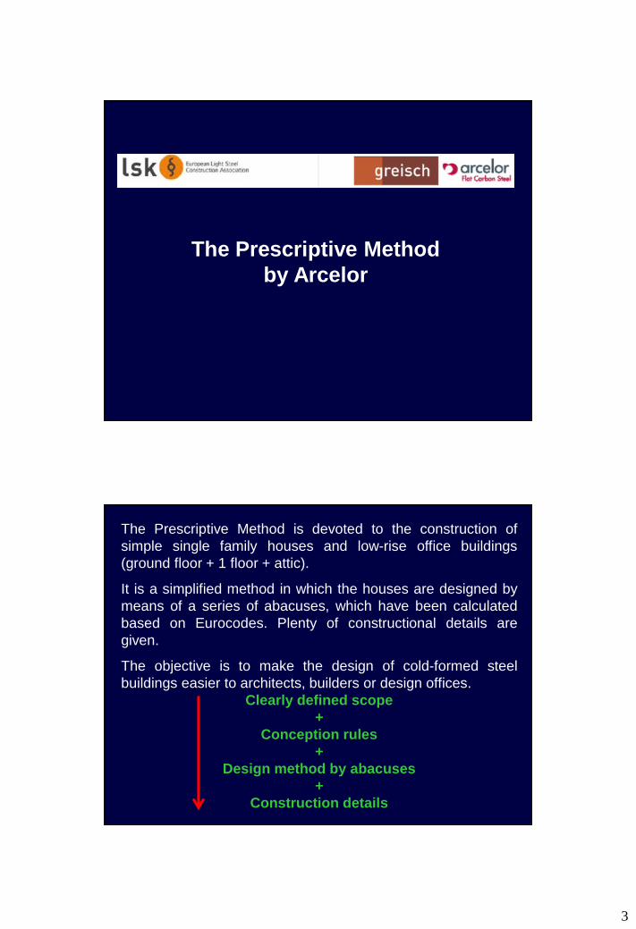
The Prescriptive Method is devoted to the construction of
simple single family houses and low-rise office buildings
(ground floor + 1 floor + attic).
It is a simplified method in which the houses are designed by
means of a series of abacuses, which have been calculated
based on Eurocodes. Plenty of constructional details are
given.
The objective is to make the design of cold-formed steel
buildings easier to architects, builders or design offices.
Clearly defined scope
+
Conception rules
+
Design method by abacuses
+
Construction details

4
Scope
The method applies to single family houses or office buildings
with ground floor plus one first floor and allows the possibility of
an attic, depending on the type of roofing.
Only flat roofs or roofs with two-equal slopes are considered.
The structure is made of cold-formed steel profiles, basically C-
U shaped which are joined by self-drilling screws.
The structure is subdivided in three main parts roof, floor and
walls/façades.
Several abacuses are provided for each part in order to
determine which profiles must be used. The separation
between studs or between purlins is assumed to be 600 mm
max, whereas the separation between trusses is between 600
and 1200 mm.
The method is restricted to a series of European countries and
cannot be used if some given values for loads are overpassed:
• The countries are: Belgium, Luxembourg, Spain, France,
Netherlands and Portugal.
• Maximum loads: snow < 300 kg/m2 and wind < 1600
kg/m2.
The structural elements, connections and steel grade are:
• Steel grade: 350 N/mm2 (galvanised steel).
• C-U profiles of a given range of dimensions.
C profiles : h [120 220]; b [60]; c [12]; t [1,5 2]
U profiles : h [126]; b [66]
Purlins gatherer: h[124 224]; b1 [50]; b2 [123]; t[2]

5
• Fasteners:
1. Self-tapping screws 4.8 and 6.3.
2. M6 to M16 bolts of quality 8.8 are used for the steel trusses.
3. M10 for the anchorage, except for frames with X-braces in
which chemical anchors M20 are used.
Loads
• Permanent loads (G), for the different elements of the
structure. The method gives the values for the different
types coverings. Thus, for example, for a light roof made of
sandwich panels G equals 25 kg/m2 or for a composite floor
steel + concrete, G equals 260 kg/m2.
• Imposed loads (Q) are defined based on EN1991-1-1:2002:
1. Floors: the method considers two categories of buildings:
category A (domestic, residential areas with a qk of 2
kN/m2) and category B (office areas, with a qk of 3.0
kN/m2).
2. Roofs: The method considers category H, corresponding to
non-accessible roofs, in which qk is defined depending on
the slope of the roof.

6
Loads
• Snow loads (S) are defined on the basis of EN1991-1-
3:2003. Several abacuses are given to calculate the snow
load sk depending on the geographical area and the
altitude where the buildings is placed.
• Wind pressure (W) are defined based on EN1991-1-
4:2005. The wind pressures can also be obtained from a
series of abacuses for different geographical areas, which
depend on the height of the building.
The combination of loads used to calculate the different design
abacuses, follows the rules of EN1990:2002.
Hypothesis of design
The abacus have been calculated so that the structure fulfils
the following criteria:
•Resistance and stability design criteria according to EN1993-1-
1, EN1993-1-3 and EN1993-1-5.
•Deflection criteria:
1. For the roof, max = L/200 under total loads and
max = L/250 under single variable loads;
2. For the floors: max = L/400 under total loads and
max = L/500 under single variable loads;
3. For the studs: max = L/500 under variable loads.
•Vibration of floors: The prescriptive method applies, in order to
ensure the comfort of the occupants, the following limitation: f ≥
5 Hz.

7
Roofs
Different types of covering materials are taking into account, i.e.
light roofs covered by sandwich panels and heavy roofs with
tiles + lathwork + insulation.
The roof frame has to fall into line with studs!!!
In order to design the roof, the user has to use the
appropriate abacus with the following data:
• Geometrical parameters: Slope of the roof, overflowing,
spacing (600 mm or 1200 mm, when allowed) and span.
In the case of framework, also the position of the tie-beam.
• Loads as described: snow and wind loads obtained from
the corresponding abacuses, the dead load depending on
the roofing panel and the live load.

8
For a given set of data, the user gets:
- the profiles to use and
- the reaction loads that will be used later on for the
design of studs and lintels.
Geometrical parameters:
-Slope
-Overflowing of the roof: Y/N
-Span
Load parameters:
-Snow load
-Wind load
-Live load
-Dead load
ABACUSES
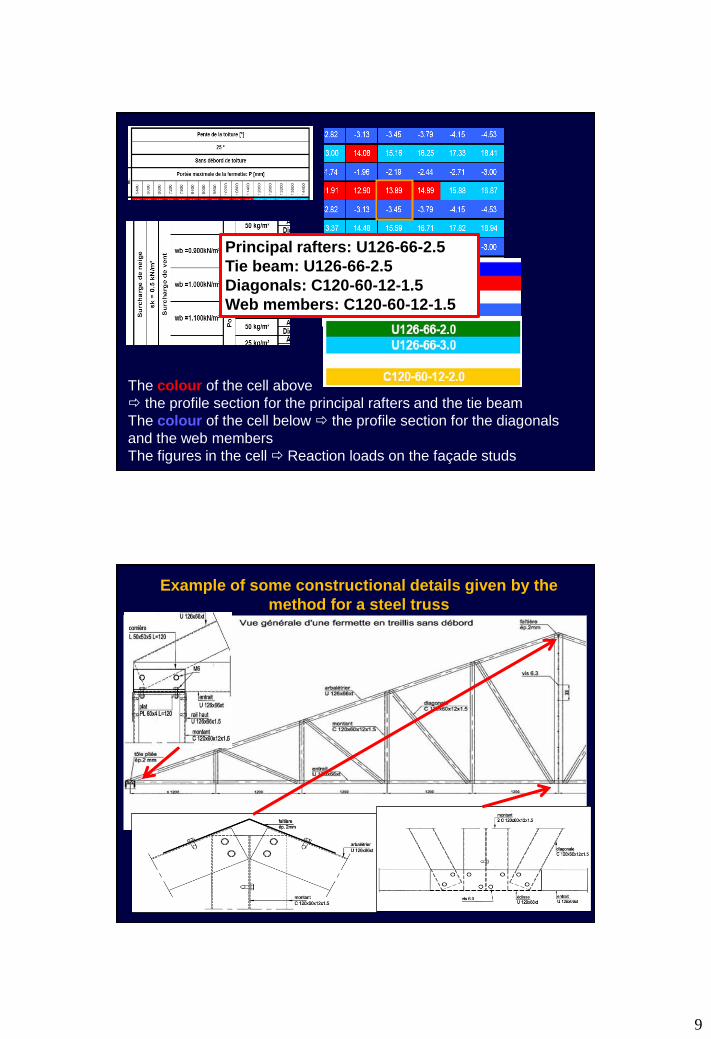
Abacus for the design of a steel truss
9
The colour of the cell above
the profile section for the principal rafters and the tie beam
The colour of the cell below the profile section for the diagonals
and the web members
The figures in the cell Reaction loads on the façade studs
Principal rafters: U126-66-2.5
Tie beam: U126-66-2.5
Diagonals: C120-60-12-1.5
Web members: C120-60-12-1.5
Example of some constructional details given by the
method for a steel truss

10
The basic constitutive elements found in this system:
• Bottom chord: U126X66xt, with t from the abacuses.
• Top chord: U126X66xt, with t obtained from the abacuses.
• Vertical stud: C120x60x12x1.5. The central one composed
of two back-to-back profiles joined with 6.3 screws.
• Diagonal girders: C120x60x12x1.5.
• Steel ridge tile: 2 mm thick is fixed to the top chord with 3
6.3 screws.
• Angles and special devices for joining the trusses to the
façades are also defined.
• Ties to keep the trusses well separated, composed of tubes
27*1 S350.
• Bracing systems, crosses with U40X40X2.0 S350 profiles
are defined. Constructional details for the disposition of
these bracings are also provided.
General information given by the method for steel trusses
The method defines also the space between the different
members, both between trusses or between the girders of the
truss.
Description about the fixing of the roof panels, the false
ceilings or the fixing of the trusses to the vertical structure is
provided.
The number and types of self-drilling screws for the truss and
its bracings are also given, with the reference to the proper
constructional details.
General information given by the method for steel trusses

11
Similar information / abacuses are given for:
Floors The method considers 3 different types of floors (from light
floors, to composite steel-concrete slabs). The spacing
between purlins is defined as a maximum of 600 mm and they
must be supported over a stud or a lintel.
The joists have to fall into line with studs!
12
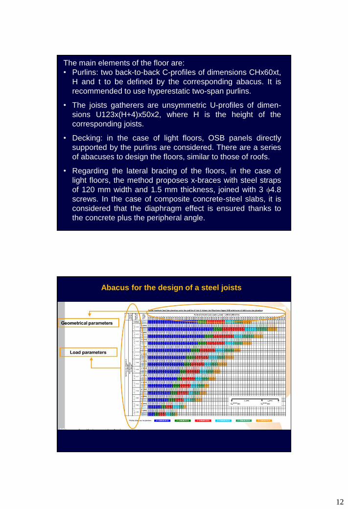
The main elements of the floor are:
• Purlins: two back-to-back C-profiles of dimensions CHx60xt,
H and t to be defined by the corresponding abacus. It is
recommended to use hyperestatic two-span purlins.
• The joists gatherers are unsymmetric U-profiles of dimen-
sions U123x(H+4)x50x2, where H is the height of the
corresponding joists.
• Decking: in the case of light floors, OSB panels directly
supported by the purlins are considered. There are a series
of abacuses to design the floors, similar to those of roofs.
• Regarding the lateral bracing of the floors, in the case of
light floors, the method proposes x-braces with steel straps
of 120 mm width and 1.5 mm thickness, joined with 3 4.8
screws. In the case of composite concrete-steel slabs, it is
considered that the diaphragm effect is ensured thanks to
the concrete plus the peripheral angle.
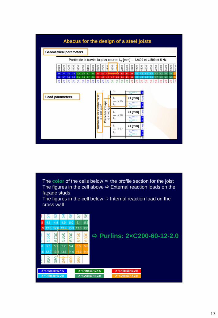
Abacus for the design of a steel joists
13
Abacus for the design of a steel joists
The color of the cells below the profile section for the joist
The figures in the cell above External reaction loads on the
façade studs
The figures in the cell below Internal reaction load on the
cross wall
Purlins: 2×C200-60-12-2.0

14
Example of some constructional details given by the
method for a steel joists
Façades
A stud-spacing of 600 mm is considered.
Two different types of covering materials are considered:
sandwich panels and stone-finishing.
The different structural elements are the following:
Studs: C-profiles 120x60x12x1.5 which can be simple or
doubled.
Tracks: U-profiles 126X66X1.5.
Lintels: built with 2 C-profiles back-to-back joined to the
studs by clip-angles.
X-bracings: two or three modules for the lateral resistance
Structural details are provided for the connection between
façades. The method provides different abacuses for the
design of lintels, X-bracings and studs.
15
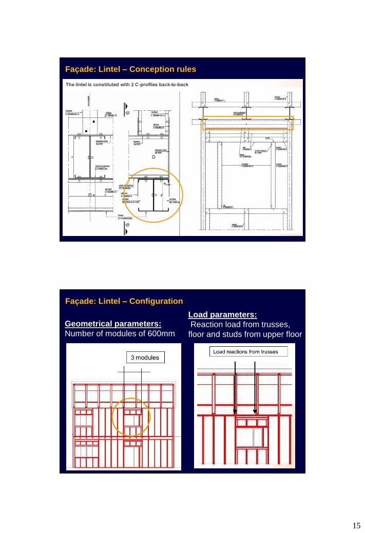
Façade: Lintel – Conception rules
Façade: Lintel – Configuration
Geometrical parameters:
Number of modules of 600mm
Load parameters:
Reaction load from trusses,
floor and studs from upper floor

16
Façade: Lintel – Configuration
• Sections of the lintel
• Reaction load to consider for studs adjacent to lintel
Geometrical parameters:
3 modules of 600mm
Load parameters:
Reaction load from trusses
15,88kN on the first and the
third studs
0 kN on the others
ABACUSES
Façade: Lintel – Design

17
Façade: Lintel – Design
Façade: Wind bracings – Conception rules

18
• Number of modules of wind bracings in the facade
• Number of screws at each edge of the flat profile
Geometrical parameters:
- Length of side facade
- Slope of the roof
- Height of the studs for each floor
Surface of side facade to be
considered for the design of wind
bracing (Ground floor and first floor)
Load parameters:
Wind load
ABACUSES
Façade: Wind bracings – Design
Façade: Wind bracings – Design

19
Façade: Wind bracings – Design
Façade: Studs – Conception rules
The façade is constituted with C120
profiles (sometimes double).
The C-profiles are placed alternately.
The interax is 600mm
20
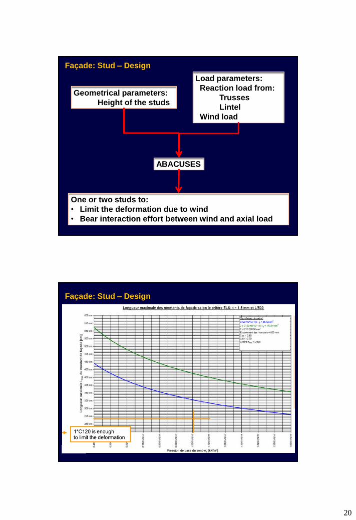
One or two studs to:
• Limit the deformation due to wind
• Bear interaction effort between wind and axial load
Geometrical parameters:
Height of the studs
Load parameters:
Reaction load from:
Trusses
Lintel
Wind load
ABACUSES
Façade: Stud – Design
Façade: Stud – Design

21
Façade: Stud – Design
• A simple but complete method;
• Allow a larger diffusion of the system thanks to a
wide accessibility
• Saving of time and money
• Efficient method
Weight difference < 10% in comparison with a
specialized software method
Conclusions

22
Constantin’s Family House, Ploiesti,
Romania
• Slender sections prone to local buckling;
• Non-plastic;
• Non-dissipative.
Cold-formed steel framing for housing are
usually made of class 4 or 3 sections e.g.
Seismic design codes are either restrictive
or penalizing the use of these structures in
seismic zones.
23
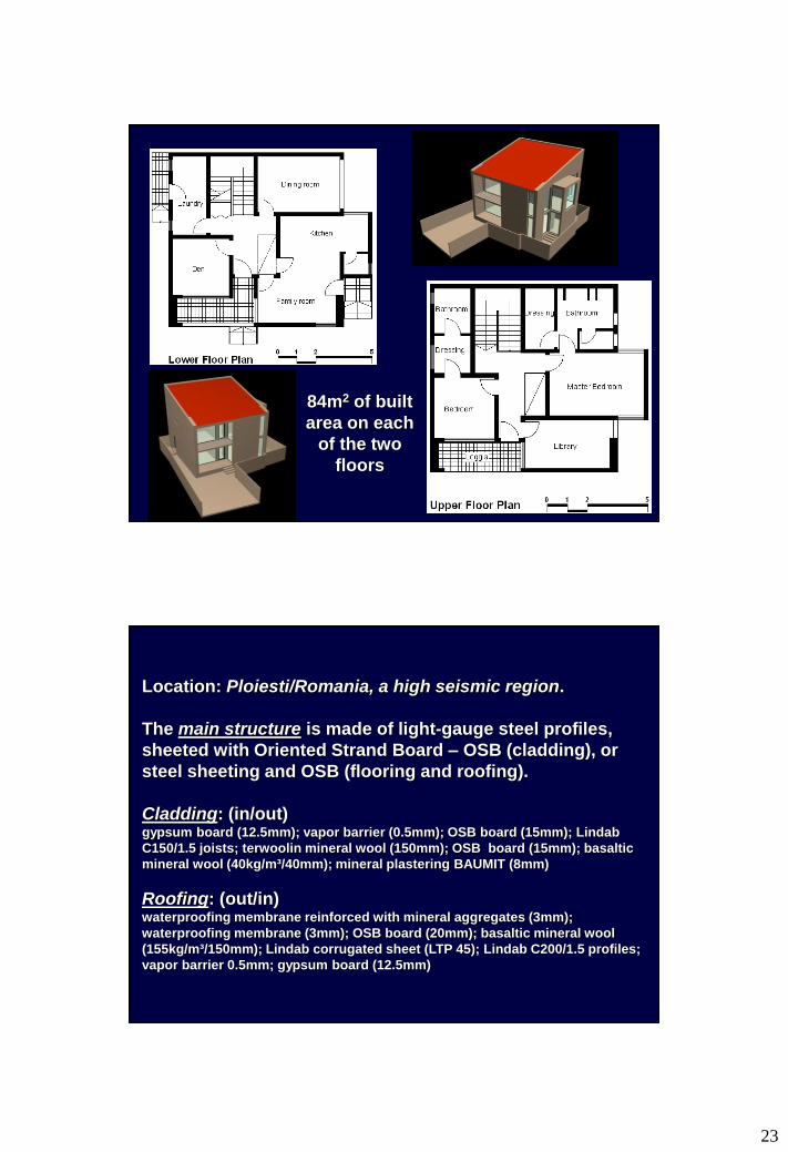
84m2 of built
area on each
of the two
floors
Location: Ploiesti/Romania, a high seismic region.
The main structure is made of light-gauge steel profiles,
sheeted with Oriented Strand Board – OSB (cladding), or
steel sheeting and OSB (flooring and roofing).
Cladding: (in/out) gypsum board (12.5mm); vapor barrier (0.5mm); OSB board (15mm); Lindab
C150/1.5 joists; terwoolin mineral wool (150mm); OSB board (15mm); basaltic
mineral wool (40kg/m³/40mm); mineral plastering BAUMIT (8mm)
Roofing: (out/in) waterproofing membrane reinforced with mineral aggregates (3mm);
waterproofing membrane (3mm); OSB board (20mm); basaltic mineral wool
(155kg/m³/150mm); Lindab corrugated sheet (LTP 45); Lindab C200/1.5 profiles;
vapor barrier 0.5mm; gypsum board (12.5mm)
24
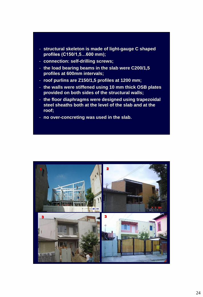
- structural skeleton is made of light-gauge C shaped
profiles (C150/1,5…600 mm);
- connection: self-drilling screws;
- the load bearing beams in the slab were C200/1,5
profiles at 600mm intervals;
- roof purlins are Z150/1,5 profiles at 1200 mm;
- the walls were stiffened using 10 mm thick OSB plates
provided on both sides of the structural walls;
- the floor diaphragms were designed using trapezoidal
steel sheaths both at the level of the slab and at the
roof;
- no over-concreting was used in the slab.
1 2
3 3
25

26
Problems during the design of such a
structure is the evaluation of the load bearing
capacity and of the rigidity of the sheathing
system of walls and slabs.
Experimental results were the basis of the
evaluation both for shear capacity and rigidity
reported to 1m length of the wall.
Design assisted by testing
where,
Es,i = total shear force induced by seismic action on “i”
direction (kN);
Rs,i = total shear wall resistance on “i” direction (kN);
Rk = characteristic strength of shear wall (kN/m);
Li = length of shear wall on “i” direction (m).
27
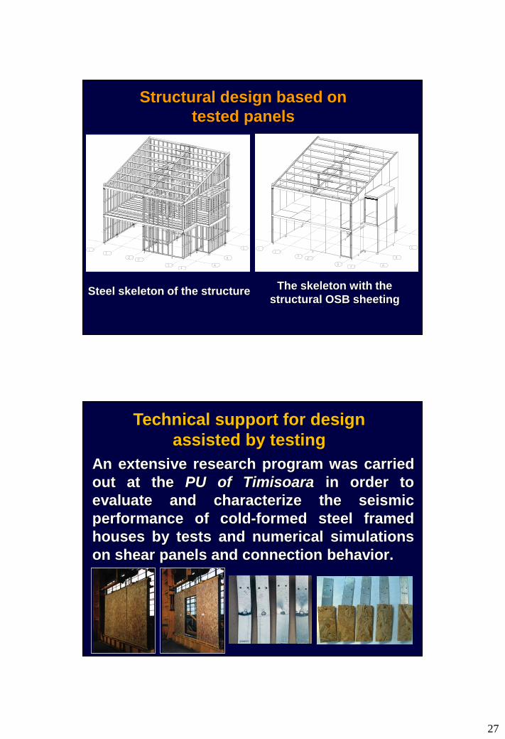
Structural design based on
tested panels
The skeleton with the
structural OSB sheeting Steel skeleton of the structure
An extensive research program was carried
out at the PU of Timisoara in order to
evaluate and characterize the seismic
performance of cold-formed steel framed
houses by tests and numerical simulations
on shear panels and connection behavior.
Technical support for design
assisted by testing
28
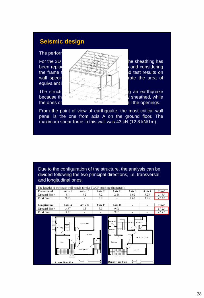
The performance of shear walls is crucial.
For the 3D analysis, the rigidity induced by the sheathing has
been replaced by equivalent cross bracings and considering
the frame to be pinned. Rigidity criteria and test results on
wall specimens have been used to calibrate the area of
equivalent braces.
The structure is subjected to torsion during an earthquake
because the walls on axes 1 and D are fully sheathed, while
the ones on axes 3, 4 and A accommodate all the openings.
From the point of view of earthquake, the most critical wall
panel is the one from axis A on the ground floor. The
maximum shear force in this wall was 43 kN (12.8 kN/1m).
Seismic design
Due to the configuration of the structure, the analysis can be
divided following the two principal directions, i.e. transversal
and longitudinal ones.

29
In a first step, the total mass of the structure is evaluated, at
the level of the first floor and at the roof level, taken into
account the loads and safety coefficients, considered for the
special combination of seismic action:
, , 2, ,1 2
n m
k j I E k i k ij i
G A Q
where:
AE,k – Characteristic value of seismic action;
0,i – Factor for combination value of the variable action i;
Qi – 0.4 for snow load and live load.
It results: (i) the total mass at the floor level Mground floor = 23.07 t
and (ii) the total mass at the roof level Mfirst floor = 11.71 t.
( ) ( )
1 0 28 2.75 9 81 23.07 11.71 262.72 kΝ
e I gS T a T g M
Considering the deformation is linear in regard with the height,
the horizontal load is distributed to both levels as follows:
1 11 r
j j
2 22 r
j j
z G 3 23.07S S 262.72 120.27 kN
(z G ) 3 23.07 7 11.71
z G 7 11.71S S 262.72 142.45 kN
(z G ) 3 23.07 7 11.71
The total seismic force applied on the structure is:
30
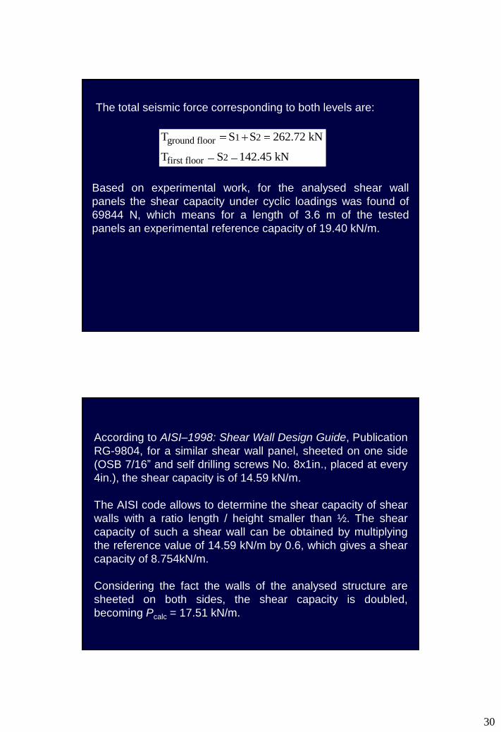
The total seismic force corresponding to both levels are:
1 2ground floor
2first floor
T S S 262.72 kN
T S 142.45 kN
Based on experimental work, for the analysed shear wall
panels the shear capacity under cyclic loadings was found of
69844 N, which means for a length of 3.6 m of the tested
panels an experimental reference capacity of 19.40 kN/m.
According to AISI–1998: Shear Wall Design Guide, Publication
RG-9804, for a similar shear wall panel, sheeted on one side
(OSB 7/16” and self drilling screws No. 8x1in., placed at every
4in.), the shear capacity is of 14.59 kN/m.
The AISI code allows to determine the shear capacity of shear
walls with a ratio length / height smaller than ½. The shear
capacity of such a shear wall can be obtained by multiplying
the reference value of 14.59 kN/m by 0.6, which gives a shear
capacity of 8.754kN/m.
Considering the fact the walls of the analysed structure are
sheeted on both sides, the shear capacity is doubled,
becoming Pcalc = 17.51 kN/m.

31
ground floorground floor
calc
first flofirst floor
T 262.72L 15.00 m < 21.55m (transversal)
P 17.51
< 17.22m (longitudinal)
TL or
calc
142.45 8.14 m < 17.12m (transversal)
P 17.51
< 12.42m (longitudinal)
The length of walls necessary to provide the shear capacity
results as:
Perete Ax. 1
OSB pe ambele fete
Perete Ax. 1'
OSB pe ambele fete
Perete Ax. 2
OSB pe ambele fete
Perete Ax. 2'
OSB pe ambele fete
Perete Ax. 4
OSB pe ambele fete
Perete Ax. 3
OSB pe ambele fete
Perete Ax. A
OSB pe ambele fete
Perete Ax. B
OSB pe ambele fete
Perete Ax. C
OSB pe ambele fete
Perete Ax. D
OSB pe ambele fete
Supply
Transversal:
Lgf =21.55 m, Lff =17.12 m
Longitudinal:
Lgf =17.22 m, Lff =12.42 m Demand
Lg =15 m, Lf =8.14m
32
Conclusions
• Structural design based on tested panels
confirmed;
• Besides the advantage of high quality/price
ratios, both for structural performance and
building physics characteristics, such a light
gauge steel framed house can be considered
the ideal solution for seismic zones.
Steps to apply Prescriptive Method
on residential buildings in Turkey
33
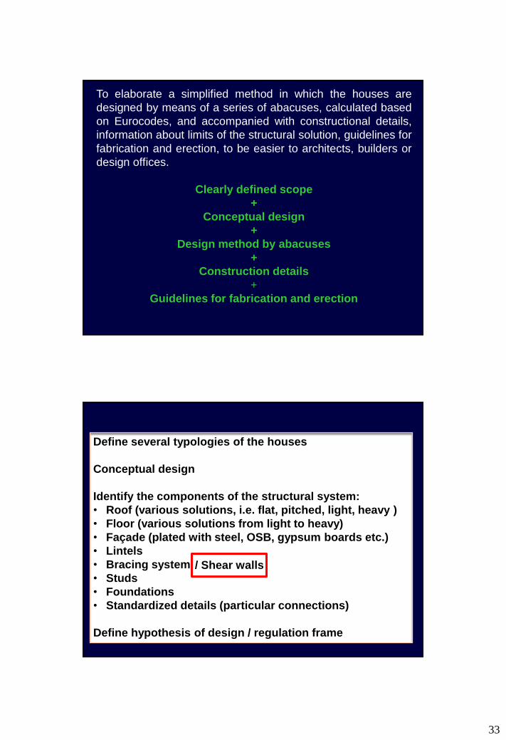
To elaborate a simplified method in which the houses are
designed by means of a series of abacuses, calculated based
on Eurocodes, and accompanied with constructional details,
information about limits of the structural solution, guidelines for
fabrication and erection, to be easier to architects, builders or
design offices.
Clearly defined scope
+
Conceptual design
+
Design method by abacuses
+
Construction details
+
Guidelines for fabrication and erection
Define several typologies of the houses
Conceptual design
Identify the components of the structural system:
• Roof
• Floor
• Lintels
• Bracing system / Shear walls
• Studs
• Foundations
• Standardized details (particular connections)
Define hypothesis of design
Define several typologies of the houses
Conceptual design
Identify the components of the structural system:
• Roof (various solutions, i.e. flat, pitched, light, heavy )
• Floor (various solutions from light to heavy)
• Façade (plated with steel, OSB, gypsum boards etc.)
• Lintels
• Bracing system
• Studs
• Foundations
• Standardized details (particular connections)
Define hypothesis of design / regulation frame
/ Shear walls
34

35

36
EN1993-1-1 (2005). Eurocode 3: Design of steel structures -
Part 1-1: General rules and rules for buildings. ECS, Brussels.
EN1993-1-2 (2005). Eurocode 3: Design of steel structures -
Part 1-2, Design of Steel Structures, General rules. Structural
fire design, ECS, Brussels, Belgium.
EN1993-1-3 (2006). Eurocode 3: Design of steel structures. Part
1-3: General Rules. Supplementary rules for cold-formed thin
gauge members and sheeting. ECS, Brussels, Belgium.
EN1993-1-5 (2006). Eurocode 3: Design of steel structures -
Part 1-5: Plated structural elements. ECS, Brussels, Belgium.
EN1993-1-8 (2005). Eurocode 3: Design of steel structures. Part
1-8: Design of joints. ECS, Brussels, Belgium.
EN1998-1 (2004). Eurocode 8 – Design of structures for
earthquake resistance - Part 1: General rules, seismic actions
and rules for buildings. ECS, Brussels, Belgium.
EN1090 (2008). Execution of steel structures and aluminium
structures - Part 2: Technical requirements for steel structures.
ECS, Brussels, Belgium.
37
ECCS_88 (1995). European Recommendations for the
Application of Metal Sheeting acting as a Diaphragm,
Publication P088, ECCS, Brussels, Belgium.
ECCS_124 (2008). The Testing of Connections with Mechanical
Fasteners in Steel Sheeting and Sections. Publication 124,
ECCS, Brussels, Belgium.
ECCS_127/CIB_320 (2009). ECCS TC7 TWG 7.9 / CIB
Working Commission W056. Preliminary European
Recommendations for the Testing and Design of Fastenings for
Sandwich Panels. Publication ECCS no. 127/CIB no. 320,
Belgium.
EN300 (1997). Oriented strand boards OSB - Definitions,
classification and specifications. ECS, Brussels, Belgium.
EN10002-1 (2001). Tensile testing of metallic materials. Method
of test at ambient temperature. ECS, Brussels, Belgium.
EN1990 (2002). Eurocode – Basis of structural design. ECS,
Brussels, Belgium.
EN1991-1-1 (2002). Eurocode 1: Actions on structures - Part 1-
1: General actions-Densities, self-weight, imposed loads for
buildings. ECS, Brussels, Belgium.
EN1991-1-3 (2003). Eurocode 1: Actions on structures - Part 1-
3: General actions - Snow loads. ECS, Brussels, Belgium.
EN1991-1-4 (2005). Eurocode 1: Actions on structures - Part 1-
4: General actions - Wind actions. ECS, Brussels, Belgium.
EN1991-1-5 (2003). Eurocode 1: Actions on structures - Part 1-
5: General actions - Thermal actions. ECS, Brussels, Belgium.
EN1991-1-2 (2002). Eurocode 1: Actions on structures - Part 1-
2: General actions - Actions on structures exposed to fire. ECS,.
EN1991-1-6 (2005). Eurocode 1: Actions on structures - Part 1-
6: General actions - Actions during execution. ECS, Brussels.
EN1991-1-7 (2006). Eurocode 1: Actions on structures - Part 1-
7: General actions - Accidental actions. ECS, Brussels, Belgium.

38
Load parameters:
-Dead load
-Live load
-Snow load
-Wind load
-Seismic action
Vertical loads:
-Dead load
-Live load
-Snow load
Horizontal loads:
-Wind load (X-bracings)
-Seismic action (X-bracings)
Horizontal loads:
-Seismic action
(shear panels)
ABACUSES
Design assisted by
experimental or/and
numerical testing
For a given set of data, the user gets:
- the profiles and connections to use and
- the reaction loads that will be used for the design of
elements (from roof to foundations).
39
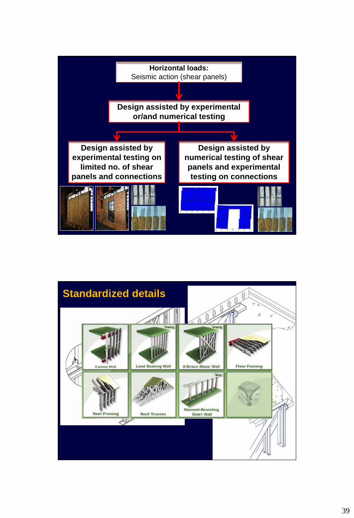
Horizontal loads:
Seismic action (shear panels)
Design assisted by experimental
or/and numerical testing
Design assisted by
experimental testing on
limited no. of shear
panels and connections
Design assisted by
numerical testing of shear
panels and experimental
testing on connections
Standardized details
40
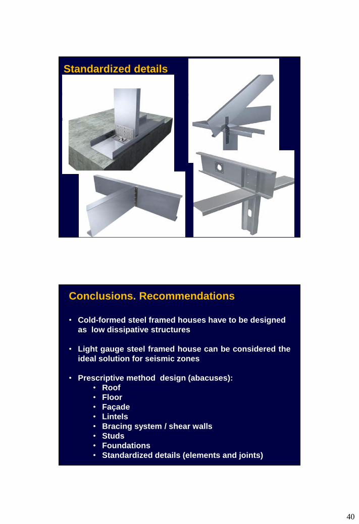
Standardized details
Conclusions. Recommendations
• Cold-formed steel framed houses have to be designed
as low dissipative structures
• Light gauge steel framed house can be considered the
ideal solution for seismic zones
• Prescriptive method design (abacuses):
• Roof
• Floor
• Façade
• Lintels
• Bracing system / shear walls
• Studs
• Foundations
• Standardized details (elements and joints)
41
Conclusions. Recommendations
• Pre-calibrated wall-stud shear panel units using:
numerical or experimental tests for all-steel
solutions;
experimental tests for composite solutions (OSB-
steel, GB-steel etc.);
calibrated models based on experimental tests for
connections always .
• A simple but complete method;
• Efficient method, saving time and money