Embed Size (px)
Citation preview

AMD. 1/2018
STRUCTURES DESIGN MANUAL FOR HIGHWAYS AND RAILWAYS
2013 Edition
AMENDMENT NO. 1/2018
June 2018
HIGHWAYS DEPARTMENT The Government of the Hong Kong Special Administrative Region

AMD. 1/2018
STRUCTURES DESIGN MANUAL FOR HIGHWAYS AND RAILWAYS
2013 Edition
AMENDMENT NO. 1/2018
INTRODUCTION
The “Structures Design Manual for Highways and Railways” (SDM) published by the Government of the Hong Kong Special Administrative Region sets out standards and provides guidance for the design of highway and railway structures in Hong Kong. In 2018, Highways Department conducted a review on the structural design of noise barriers/enclosures and the guidelines for making provision for accommodation of utilities on highway structures. Following the review, amendments to Chapters 3 and 16 of the SDM are made and a new appendix giving guidance on the structural design of noise barriers/enclosures is added to the SDM.
AMENDMENT DETAILS
The following amendments are made :
1. CONTENTS Pages 6, 14, 15, 16 and 19 of the SDM are replaced by Replacement Sheets 1 to 5 respectively.
2. CHAPTER 3 Pages 47, 53, 53A and 53B of the SDM are replaced by Replacement Sheets 6 to 9 respectively.
3. CHAPTER 16 Pages 212 and 213 of the SDM are replaced by Replacement Sheets 10 to 11 respectively.
4. APPENDIX F Pages F1 to F16 are added by Replacement Sheets 12 to 27.

AMD. 1/ 2018
CHAPTER 3 ACTIONS 33
3.1 GENERAL 33
3.2 COMBINATIONS OF ACTIONS 33
3.2.1 General 33 3.2.2 Crack Width Verification Combination 38 3.2.3 Tensile Stress Verification Combinations for Prestressed Concrete
Members 38
3.3 DEAD LOAD AND SUPERIMPOSED DEAD LOAD 39
3.4 WIND ACTIONS 40
3.4.1 General 40 3.4.2 Simplified Procedure for Determining Peak Velocity Pressure 41 3.4.3 Full Procedure for Determining Peak Velocity Pressure 42 3.4.4 Dynamic Response Procedure 46 3.4.5 Wind Forces 47 3.4.6 Force Coefficients and Pressure Coefficients 47
AMD. 3.4.7 Reference Area 53A 1/2018 3.4.8 ULS Partial Factors 53B 3.4.9 ψ Factors 53B
3.5 TEMPERATURE EFFECTS 54
3.5.1 General 54 3.5.2 Uniform Temperature Components 54 3.5.3 Temperature Difference Components 56 3.5.4 Simultaneity of Uniform and Temperature Difference Components 60 3.5.5 Coefficient of Thermal Expansion 60 3.5.6 ULS Partial Factors 60 3.5.7 ψ Factors 60
3.6 ACCIDENTAL ACTIONS 60
3.6.1 General 60 3.6.2 Accidental Actions Caused by Road Vehicles 61 3.6.3 Accidental Actions Caused by Derailed Rail Traffic under or
adjacent to Structures 66 3.6.4 Accidental Actions Caused by Ship Traffic 67
3.7 TRAFFIC ACTIONS 67
3.7.1 General 67 3.7.2 Actions on Road Bridges 67 3.7.3 Actions on Footways, Cycle Tracks and Footbridges 72 3.7.4 ULS Partial Factors 73 3.7.5 ψ Factors 73
3.8 SEISMIC ACTIONS 73
6Replacement Sheet 1 of 27

AMD. 1/2018
LIST OF TABLES Page No.
Table 2.1 – Reliability Classification 24
26Table 2.2 – Classification of Highway Structures for Design Checking
28Table 2.3 – Scope of Design Checking
31Table 2.4 – Highway Structures Design and Check Certificate
Table 3.1 – Values of ψ Factors for Road Bridges 34
Table 3.2 – Values of ψ Factors for Footbridges 34
Table 3.3 – Design Values of Actions (EQU) (Set A) 35
Table 3.4 – Design Values of Actions (STR/GEO) (Set B) 36
Table 3.5 – Design Values of Actions (STR/GEO) (Set C) 37
Table 3.6 – Wind Velocities 40
Table 3.7 – Peak Velocity Pressure q p for Simplified Procedure 41
Table 3.8 – Exposure to Wind – Simplified Procedure 42
Table 3.9 – Peak Velocity Pressure q p(z) and Hourly Mean Velocity Pressure q’(z) for Full Procedure 44
Table 3.10 – Terrain and Bridge Factor sb(z) and Hourly Velocity Factor sc(z) 45
Table 3.11 – Force Coefficient cf, x for a Single Truss 48
Table 3.12 – Shielding Factor η 48
Table 3.13 – Force Coefficient cf, x for Covered Footbridges -5º ≤ α ≤ +5º 51
Table 3.14 – Force Coefficient cf, z for Covered Footbridges -5º ≤ α ≤ +5º 51
Table 3.15 – Force Coefficient cf, x for Covered Footbridges -20º<α<-5º & +5º<α<+20º 52
Table 3.16 – Force Coefficient cf, z for Covered Footbridges -20º<α<-5º & +5º<α<+20º 52
Table 3.16a – Pressure Coefficients c p, net for Vertical Noise Barriers and Vertical Parts of Cantilever Noise Barriers on Bridges 53 AMD.
Table 3.16b – Pressure Coefficients cp,ne t for Inclined Parts of Cantilever Noise Barriers on At-Grade Roads and on Bridges 53A
Table 3.17 – Uniform Bridge Temperature 55
Table 3.18 – Adjustment to Uniform Bridge Temperature for Deck Surfacing 55
14Replacement Sheet 2 of 27
1/2018

AMD. 1/2018
Table 3.19 – Values of ΔT for Superstructure Type 1 58
Table 3.20 – Values of ΔT for Superstructure Type 2 58
Table 3.21 – Values of ΔT for Superstructure Type 3 59
Table 3.22 – Application of Various Checks to Different Types of Bridge Decks 61
Table 3.23 – AADT Values for Factor F 2 and F8 62
Table 3.24 – Equivalent Static Design Forces due to Vehicular Impact on Members Supporting Road Bridges over or adjacent to Roads 63
Table 3.25 – Equivalent Static Design Forces due to Vehicular Impact on Members Supporting Foot/Cycle Track Bridges over or adjacent to Roads 64
Table 3.26 – Equivalent Static Design Forces due to Vehicular Impact on Members Supporting Sign Gantries over or adjacent to Roads 65
Table 3.27 – Equivalent Static Design Forces due to Vehicular Impact on Bridge Superstructures 66
Table 3.28 – Adjustment Factors αQi and αqi for Load Model 1 68
Table 3.29 – Assessment of Groups Traffic Loads (Characteristic Value of the Multi-Component Actions) 70
Table 3.30 – Forces due to Collision with Vehicle Restraint Systems for Determining Global Effects 71
Table 4.1 – Importance Class and Importance Factor 75
Table 5.1 – Strength and Short Term Elastic Modulus of Concrete 77
Table 5.2 – Nominal Concrete Cover and Crack Width Requirements 84
Table 5.3 – Allowable Flexural Tensile Stress under Tensile Stress Verification Combination for Prestressed Concrete Members Case 2 85
Table 5.4 – Additional Modifications to BS EN 1992-1-1, BS EN 1992-2, the UK NAs to BS EN 1992-1-1 and BS EN 1992-2, PD 6687-1 and PD 6687-2 91
Table 6.1 – Additional Modifications to BS EN 1993-1, BS EN 1993-2, the UK NAs to BS EN 1993-1 and BS EN 1993-2 and PD 6695-2 96
Table 7.1 – Additional Modifications to BS EN 1994-1-1, BS EN 1994-2, the UK NAs to BS EN 1994-1-1 and BS EN 1994-2, and PD6696-2 100
Table 8.1 – Classification of Bearings 103
Table 8.2 – Bridge Bearing Schedule 104
Table 9.1 – Schedule of Movement Joint 113
15Replacement Sheet 3 of 27

AMD. 1/2018
Table 11.1 – Vehicle Parapet Groups 127
Table 11.2 – Vehicle Characteristics 128
Table 11.3 – Selection Guideline 129
Table 11.4 – Scoring System for Selection of L3 Containment Level Bridge Parapets 130
Table 11.5 – Parapet Heights 131
Table 11.6 – Strength of Reinforced Concrete Parapets 132
Table 11.7 – Dimensions for Vehicle Parapets 133
Table 11.8 – Minimum Design Loads for Pedestrian and Bicycle Parapets 134
Table 11.9 – Dimensions for Pedestrian Parapets 134
Table 11.10 – Dimensions for Bicycle Parapets 135
Table 13.1 – Headroom 151
Table 13.2 – Horizontal Clearance 151
Table 13.3 – Compensation for Vertical Curvature 152
Table 14.1 – uPVC Drain Pipes 154
16 Replacement Sheet 4 of 27

AMD. 1/2018
APPENDICES Page No.
APPENDIX A LIST OF EUROCODES, UK NATIONAL ANNEXES AND PUBLISHED DOCUMENTS A1
APPENDIX B EXAMPLES OF COMBINATIONS OF ACTIONS FOR TYPICAL ROAD BRIDGES B1
APPENDIX C BACKGROUND TO THE WIND ACTION PROVISIONS FOR HIGHWAY STRUCTURES AND RAILWAY BRIDGES C1
APPENDIX D BACKGROUND ON AERODYNAMIC EFFECTS ON BRIDGES D1
APPENDIX E GUIDANCE FOR WIND TUNNEL TESTING E1
APPENDIX F GUIDANCE ON STRUCTURAL DESIGN OF NOISE BARRIERS/ENCLOSURES
F1 AMD. 1/2018
19
Replacement Sheet 5 of 27

AMD. 1/2018
vr(z), vs and c o(z) are defined in Clause 3.4.4.1
sb(z) is the terrain and bridge factor given in Table 3.10
K1U is the factor to cover the uncertainty of prediction of wind velocity and shall be taken as 1.1
K1A is the coefficient selected to give an appropriate low probability of occurrence of the severe forms of oscillation and shall be taken as 1.4.
(3) The wind speed criteria for wind tunnel testing required in PD 6688-1-4 Clause A.5, shall be taken as :
K [v ( )z + 2vd ( )z ]v = K r WO 1U 1A 3
v r zwα = K1U K1Av ( )
r ( ) + vd ( )z ][v z vWE = K1U K1A 2
where vr(z) is defined in Clause 3.4.4.1
vd(z), K1U and K 1A are defined in Clause 3.4.4.2(2)
s ( ) z Angle of wind inclination α = α ± 7
b −1 . sc z( )
3.4.5 Wind Forces
(1) The simplified method given in Clause 8.3.2(1) of BS EN 1991-1-4 shall not be followed.
(2) The size factor c s and the dynamic factor c d, shall both be taken as 1.0 for bridges that a “dynamic response procedure” is not needed.
AMD. 3.4.6 Force Coefficients and Pressure Coefficients 1/2018
(1) In addition to the force coefficients given in Clause 8.3.1 of BS EN 1991-1-4 and Table NA.8 of the UK NA to BS EN 1991-1-4, the force coefficients given in Clauses 3.4.6.1 to 3.4.6.5 below shall be followed.
AMD. (2) The pressure coefficients for noise barriers and noise enclosures given in Clauses 1/2018 3.4.6.6 and 3.4.6.7 below shall be followed.
47
Replacement Sheet 6 of 27

AMD. 1/2018
(7) Ramps will similarly experience wind forces greater than those acting on the adjacent main span. The values recommended above for stairways shall also be used for ramps.
(8) Where any additional wind tunnel tests are required, or any further guidance on interpretation or procedures for carrying out tests is required, the additional guidance given in Clause A.5 of PD 6688-1-4 and Appendix E of this Manual should be followed where appropriate.
3.4.6.6 Noise Barriers
(1) The net pressure coefficients cp,net of vertical noise barriers and vertical parts of cantilever noise barriers on at-grade roads shall refer to Clause 7.4.1 of BS EN 1991-14.
(2) The net pressure coefficients cp,net of vertical noise barriers and vertical parts of cantilever noise barriers on bridges shall refer to Table 3.16a.
(3) The net pressure coefficients c p, net of inclined parts of cantilever noise barriers on at-grade roads and on bridges shall refer to Table 3.16b. AMD.
1/2018
(4) The shelter factors for walls and fences given in Clause 7.4.2 of BS EN 1994-1-4 shall not be used.
(5) Guidance on the design of noise barriers is given in Appendix F of this Manual.
Table 3.16a – Pressure Coefficients c p, ne t for Vertical Noise Barriers and Vertical Parts of Cantilever Noise Barriers on Bridges
Zone Length to height ratio (l/h)
A B C D
l/h = 5 2.9 2.0 1.4 1.4 l/h ≥ 10 4.0 2.7 1.8 1.5
Note: (1) Refer to Figure 7.19 of BS EN 1991-1-4 and Figures F1 and F2 of this Manual for meanings of the notation.
53
Replacement Sheet 7 of 27

AMD. 1/2018
Table 3.16b – Pressure Coefficients cp,net for Inclined Parts of Cantilever Noise Barriers on At-Grade Roads and on Bridges
Zone Length to height ratio (l/h)
A B C D
l/h = 5 1.8 -2.5
1.6 -2.1
1.2 -1.5
1.0 -1.2
l/h ≥ 10 2.8 -3.2
2.6 -3.0
1.5 -2.2
1.2 -1.4
Notes: (1) Refer to Figure 7.19 of BS EN 1991-1-4 and Figures F1 and F2 of this Manual for meanings of the notation.
(2) Positive cp,net = downward wind load ; negative cp,net = upward wind load.
(3) The pressure coefficients are applicable to inclined parts: (i) which slope upward with the pitch angle between 25° and 45°; and (ii) with lc/h between 0.2 and 1, where lc is the length of the inclined part.
AMD. 1/2018
3.4.6.7 Noise Enclosures
(1) Noise enclosures are open structures with large openings on both ends or on three sides in the case of semi-enclosures. The pressure coefficients given in BS EN 1991-1-4 may not be applicable to such structures. The pressure coefficients to be adopted for design shall be based on established standards, published data or appropriate aerodynamic analysis.
(2) For noise enclosures of significant scale and/or of non-typical configurations, wind tunnel tests shall be considered to determine suitable pressure coefficients for design.
(3) When wind tunnel tests are performed, the provisions given in Clause A.5 of PD 6688-1-4 and the further guidance on wind tunnel tests given in Appendix E of this Manual shall be followed.
(4) Guidance on the design of noise enclosures is given in Appendix F of this Manual.
3.4.7 Reference Area
(1) Provisions given in BS EN 1991-1-4 Clauses 8.3.1(4) and (5) on the reference area Aref shall be followed.
(2) The Aref,x for load combination with traffic load should include the area of leeward parapet or noise barrier not screened by other members or traffic actions.
(3) For road bridges, a height of 2.5m from the level of the carriageway shall replace the height of 2m given in Clause 8.3.1(5)(a) of BS EN 1991-1-4.
53A
Replacement Sheet 8 of 27

AMD. 1/2018
(4) For footway/cycle track bridges, a height of 1.25m from the level of the finishing shall be used.
(5) For stairways and ramps, the plan area used to obtain the vertical wind load shall be the inclined area of the deck, not the projected area of the deck in plan.
3.4.8 ULS Partial Factors
(1) Appropriate ULS partial factor γQ for the design values of actions (EQU) (Set A), (STR/GEO) (Set B) and (STR/GEO) (Set C) shall be obtained in accordance with Clause 3.2.1 of this Manual. The ULS partial factors given in Tables A2.4(A) to A2.4(C) of BS EN 1990 and Tables NA.A2.4(A) to NA.A2.4(C) of the UK NA to BS EN 1990, shall not be used.
(2) For relieving effects of wind, γQ shall be taken as 1.0.
(3) The partial factors for wind actions associated with aerodynamic effects shall be obtained in accordance with Clause 3.2.1 of this Manual. The partial factors given in Clause A.1.5.4.5 of PD 6688-1-4 shall not be used.
3.4.9 ψ Factors
Appropriate ψ factor for combinations of actions shall be obtained in accordance with Clause 3.2.1 of this Manual. The ψ factors given in Tables A2.1 and A2.2 of BS EN 1990 and Tables NA.A2.1 and NA.A2.2 of the UK NA to BS EN 1990 shall not be used.
53B
Replacement Sheet 9 of 27

AMD. 1/2018
Life to first maintenance : more than 15 years, high durability as defined in BS EN ISO 12944 Part 5
Pretreatment : two-pack etch primer
Primer : two-pack epoxy zinc phosphate primer, 80 µm minimum tota l dry-film thickness
Undercoat : two-pack micaceous iron oxide epoxy undercoat, 140 µm minimum total dry-film thickness
Finish : two-pack polyurethane finish coat, 100 µm minimum tota l dry-film thickness
(c) Paint System III
To be applied to : metal sprayed surfaces
Lift to first maintenance : more than 15 years, high durability as defined in BS EN 1SO 12944 Part 5
Pretreatment : two-pack zinc tetroxychromate polyvinyl butyral pretreatment
Sealer : two-pack epoxy sealer applied by brush until absorption is complete
Primer : two-pack epoxy zinc phosphate primer, 80 µm minimum tota l dry-film thickness
Undercoat : two-pack micaceous iron oxide epoxy undercoat, 140 µm tota l minimum dry-film thickness
Finish : two-pack polyurethane finish coat, 100 µm minimum tota l dry-film thickness
(6) The aforesaid guidelines shall not be applicable to exceptionally massive steelwork, such as the steel deck of the Tsing Ma Bridge, Ting Kau Bridge, etc., where special corrosive protection system shall be considered with regard to the particular project requirements.
16.5 INCORPORATION OF UTILITY INSTALLATIONS IN HIGHWAY STRUCTURES
(1) In general no utility installations other than road lighting, emergency telephones and traffic surveillance equipment will be permitted on highway structures except in cases where there is no other viable routing available. Where other arrangements for a utility line to span an obstruction are not viable nor reasonably practical, the Highways Department may consider the accommodation of such line in a highway structure if the
AMD. 1/2018
212
Replacement Sheet 10 of 27

AMD. 1/2018
proposed accommodation will not materially affect the structure, the safe operation of traffic, the efficiency of maintenance and the overall appearance.
(2) The prior approval of Chief Highway Engineer/Bridges and Structures and the maintenance authority shall be sought on any proposal to accommodate utility installations other than road lighting, emergency telephones and traffic surveillance equipment in highway structures. The need for accommodating utility installations should be confirmed at an early stage in the design to allow the designer to make adequate and appropriate provision having due regard to the appearance and functions of the structure. The following guides are established for making provision for accommodation of utilities in highway structures :
(a) The utility lines or installations shall be accommodated in a purpose built trough accessible from the footway or verge, rather than fixed to the sides or underside of the structure using steel brackets. Funding for any additional costs for the provision of the trough is outside the ambit of this Manual and will be dealt with separately.
(b) Encasing utility installations inside the structural elements of the structure including any internal voids is not permitted.
AMD. 1/2018
(c) Unless it can be demonstrated that the risks associated with gas main installation are mitigated to an acceptable level, no gas main shall be accommodated in a highway structure.
(d) The covers, or covers and frames, for the troughs shall fit closely together to prevent lateral movement or rocking of the covers under traffic. The gap between covers, or covers and frames, shall not exceed 3 mm when assembled in continuous lengths.
(e) Where possible the space under footways and verges should be designed to permit the installation of small utilities at a later date.
16.6 MATERIALS FOR HOLDING DOWN AND FIXING ARRANGEMENTS ON HIGHWAY STRUCTURES
(1) The holding down and fixing arrangements of all sign gantries, noise barriers and the like, and all other fixtures on highways structures shall be fabricated from austenitic stainless steel. In detailing the holding down and fixing arrangements, necessary measures must be provided to prevent galvanic corrosion arising from bi-metallic contact. Stainless steel materials shall comply with Section 18 of the General Specification for Civil Engineering Works, except that Grade 1.4401 shall be replaced by Grade 1.4436 and stainless steel tube shall be Grade 1.4436.
(2) Galvanized mild steel fixing arrangements may only be used for internal fixtures.
213 Replacement Sheet 11 of 27

AMD. 1/2018
APPENDIX F
AMD. 1/2018 GUIDANCE ON STRUCTURAL DESIGN OF NOISE
BARRIERS/ENCLOSURES
F1
Replacement Sheet 12 of 27

AMD. 1/2018
CONTENTS
Page No.
TITLE PAGE F1
CONTENTS F2
F.1 INTRODUCTION F3
F.2 NOISE MITIGATION REQUIREMENTS F4
F.3 STRUCTURAL FORMS AND GEOMETRY F4
F.4 MATERIALS F9
AMD.F.5 ASSESSMENT OF WIND LOADING AND WIND TUNNEL TESTS F101/2018
F.6 SUPERIMPOSED DEAD LOAD AND LIVE LOAD F11
F.7 ACCIDENTAL ACTIONS CAUSED BY ROAD VEHICLES F12
F.8 DIRECTIONAL SIGNS F13
F.9 AESTHETIC AND OTHER DESIGN CONSIDERATIONS F15
F.10 FIRE RESISTANCE AND EMERGENCY ACCESS F15
F.11 HOLDING DEVICES AND CATCHING CONTRIVANCES F15
F.12 BIRD COLLISION F15
F.13 GLARE F16
F.14 MAINTENANCE CONSIDERATIONS F16
F2Replacement Sheet 13 of 27

AMD. 1/2018
F.1 INTRODUCTION
Noise barriers/enclosures are probably the most widely recognised form of noise mitigation measure used in Hong Kong. A proper design of noise barrier/enclosure needs due consideration in the context of providing effective noise attenuation, while also adequately addressing issues of cost, appearance, constructability, maintenance, safety and durability.
Concerns have recently arisen on the massiveness and rising cost of noise barriers/enclosures. Very often, their massiveness may be attributed to the need of providing tall and wide noise enclosures to ensure sufficient headroom and containment of multiple traffic lanes or bridge structures. However, it has been noted that the over-conservative structural designs of structural members and foundations of noise barriers/enclosures have also been a reason for the massiveness. For example, for a design of structural frames against wind actions, the structural member sizes and framing for the edge zones where wind pressure coefficients are larger compared to those in the middle zones were adopted as the typical design. In some other cases, a single wind pressure coefficient was applied to the roof of a noise enclosure enclosing multiple traffic lanes.
To achieve cost-effective design of noise barriers/enclosures and avoid over-conservative design, the Designer shall follow the guidance given in this Appendix which covers the following aspects:
AMD. 1/2018 • Noise mitigation requirements;
• Structural forms and geometry; • Materials, • Assessment of wind loading and wind tunnel tests; • Superimposed dead load and live load; • Accidental actions caused by road vehicles; • Directional signs; • Aesthetic and other design considerations; • Fire resistance and emergency access; • Holding devices and catching contrivances; • Bird collision; • Glare; and • Maintenance considerations.
In particular, wind tunnel tests shall be considered for noise enclosures of significant scale and/or of non-typical configurations to determine the wind pressure coefficients and hence the wind loadings can be derived more precisely in order to optimise the design of the structures in a more economical manner.
This Appendix shall be read in conjunction with the following documents which provide guidelines on design aspects in addition to structural design considerations:
• “Guidelines on Greening of Noise Barriers” published by Development Bureau on greening considerations;
• “Guidelines on Design of Noise Barriers” jointly published by Environmental Protection Department and Highways Department on general design considerations; and
F3 Replacement Sheet 14 of 27

AMD. 1/2018
• Bridges and Structures Division Practice Notes No. BSTR/PN/003 “Noise Barriers with Transparent Panels” on design requirements and material specifications for noise barriers with transparent panels.
F.2 NOISE MITIGATION REQUIREMENTS
A stream of traffic on a highway can create noise problems to the surroundings. The noise is transmitted through a path and then arrives at the receiver. The noise will be perceived as a problem when the noise is so high as to be a nuisance to the receiver. The severity of the problem depends on the strength of the noise source (such as heavy or light traffic) or the length of the path, that is, how large is the separation between the noise source and the receiver. An obvious way of reducing noise is to separate the sources of noise from noise sensitive uses. This is however often not practical in a compact and high-rise city to rely only on distance attenuation to cut down the noise such as in the case of tackling road traffic noise.
One of the practicable direct measures to ensure that traffic noise will stay below the statutory noise limit in Hong Kong is to provide purposely built noise barriers/enclosures. The design of noise barriers/enclosures involves due consideration on a number of aspects, including shape and geometry, dimensions and extent, materials for structural support, materials for acoustic performance, aesthetic requirements, and environmental, cost, durability and long-term maintenance considerations, etc.
The acoustic materials, locations, dimensions and shapes of noise barriers shall be as defined in the statutory Environmental Impact Assessment (EIA) studies and other non-statutory Noise Impact Assessment (NIA) studies, etc. The guidelines on acoustical design given in “Guidelines on Design of Noise Barriers” shall be followed.
F.3 STRUCTURAL FORMS AND GEOMETRY
The structural forms for noise barriers/enclosures vary but typically they are designed to hold the acoustic panels to meet the acoustic and aesthetic requirements.
Vertical noise barriers and cantilever noise barriers are usually built of structural steel frames inserted with acoustic panels. Figures F1 and F2 show the typical arrangements of a vertical noise barrier and a cantilever noise barrier respectively.
AMD. 1/2018
F4
Replacement Sheet 15 of 27
AMD. 1/2018
Figure F1 – Typical section of a vertical noise barrier
h
AMD. 1/2018 Figure F2 – Typical section of a cantilever noise barrier
lc
h
α
For noise enclosures and semi-enclosures, their structural frames may be built of steel or reinforced concrete. Noise enclosures and semi-enclosures built of structural steel frames are more common due to their lighter weight. Similar to noise barriers, the structural frames are inserted with acoustic panels to meet the acoustic and aesthetic requirements. Figures F3 and F4 show the typical arrangements of a noise enclosure and a semi-enclosure respectively.
F5 Replacement Sheet 16 of 27

AMD. 1/2018
Figure F3 – Typical section of a full noise enclosure
AMD.Figure F4 – Typical section of a noise semi-enclosure 1/2018
As shown in the above examples, the span of a noise enclosure is often governed by the width of the carriageway or structure to be enclosed. The span/depth ratio of the noise enclosure shall be optimised to achieve high structural efficiency and avoid excessive bulkiness of the structure.
Noise barriers/enclosures with excessive height and extent will not only create adverse visual impacts, but are also costly to construct. Therefore, noise barriers/enclosures shall be
F6 Replacement Sheet 17 of 27
AMD. 1/2018
designed to be fit-for-purpose as noise mitigation structures while at the same time minimising their impacts on the immediate surroundings and the wider environment. Their extent and height shall be kept to a minimum in order to achieve economical design.
The spacing of structural frames shall be optimized. In general, utilization of the capacity of the structural frames would be maximized with larger spacing of the structural frames. On the other hand, the cost of sub-frames and thickness of panel materials would also increase due to the longer span between structural frames. Therefore, the Designer shall strike a balance between spacing of structural frame, sub-frame arrangement and panel material thickness with a view to achieving economical design.
For cantilever noise barriers and noise enclosures, haunches of beams at their connections with columns shall be considered in order to reduce the overall weight of the beams.
The Designer shall also consider the method of erection and assembly at the early design stage with a view to reducing erection time and cost.
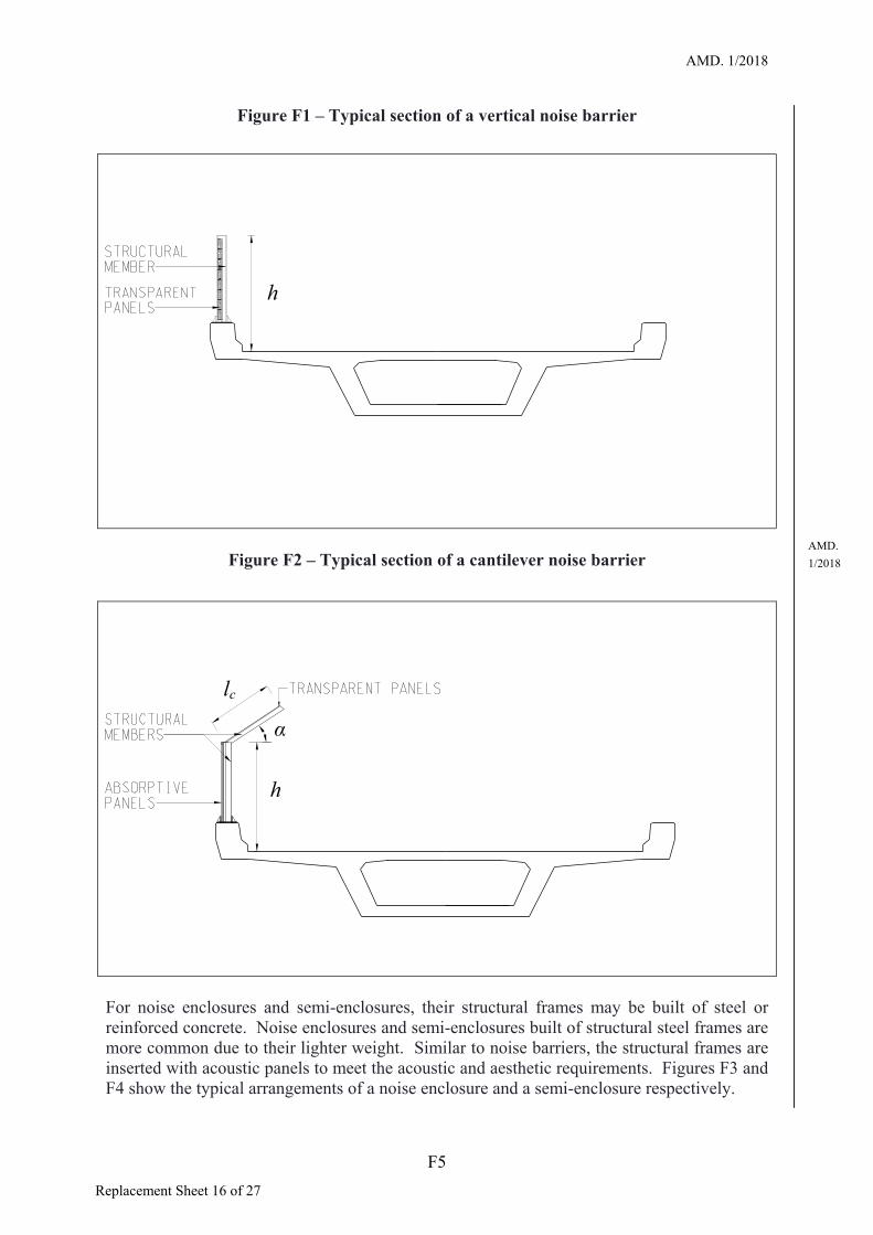
Figures F5 to F8 show some examples of noise barriers/enclosures used in Hong Kong.
Figure F5 – Vertical noise barrier at Kwun Tong Bypass (Transparent panels)
AMD. 1/2018
F7 Replacement Sheet 18 of 27

AMD. 1/2018
Figure 6 – Cantilever noise barrier at Fanling Highway (Vertical part: absorptive panels; Inclined part: transparent panels)
AMD. 1/2018
Figure F7 – Full noise enclosure at Che Kung Miu Road slip roads (Route 8) (Vertical part: transparent panels at upper portion and absorptive panels at lower
portion; Roof: absorptive panels and translucent panels)
F8 Replacement Sheet 19 of 27

AMD. 1/2018
Figure F8 – Noise semi-enclosure at Lai Chi Kok viaduct (Route 8) (Vertical part: Transparent panels; Roof: absorptive panels and transparent panels)
F.4 MATERIALS
The materials used for acoustic panels can largely be categorized as reflective and absorptive. A reflective type panel is either transparent or non-transparent. An absorptive panel is typically made up of a perforated cover sheet enclosing noise absorptive material (mineral wool or fiberglass inside and wrapped up with polyester film). In choosing a suitable material, the Designer may have his own set of considerations to suit an individual case. The “Guidelines on Design of Noise Barrier” has briefly explained the advantages and disadvantages of different materials which could be used as general guidance. The use of materials with long-term maintenance issues shall be avoided. The maintenance authority shall be consulted in this regard.
The use of lightweight materials generally reduces the costs of the structures and their foundations. The Designer should ensure maximum cost effectiveness in the choice of materials. The elements to be considered should include but not limited to the capital cost, life cycle cost (life time maintenance and replacement) and associated costs such as loading imposed on supporting frames, bridges and foundations.
For the structural frames, reinforced concrete and structural steel have been adopted. While the two materials have their own merits, in general, a reinforced concrete structure is bulkier and heavier when compared with structural steel. The use of reinforced concrete frames as structural support for noise barriers/enclosures will increase the construction time and costs and should be adopted only with justifications.
AMD. 1/2018
F9 Replacement Sheet 20 of 27

AMD. 1/2018
F.5 ASSESSMENT OF WIND LOADING AND WIND TUNNEL TESTS
Noise barriers/enclosures are often standalone structures with large surface areas subject to significant wind actions where live loading is minimal. As a result, wind loading is often the dominant loading in the design. To achieve economical design, the shape and form of the structure shall be designed with its aerodynamic performance duly considered in order to reduce the loading induced by wind. In general, simple and smooth structures with streamlined cross-sections shall be adopted and structures with sharp corners shall be avoided.
As noise barriers/enclosures are often proposed in a built-up environment, the sheltered effect of the surrounding buildings shall be taken into account. For a long noise barrier/enclosure structure, some sections of the noise barrier/enclosure may be at exposed locations while the other sections at sheltered locations. The Designer shall adopt different peak velocity pressures for different sections according to the different exposure conditions in order to achieve economical design.
The wind pressure coefficients for noise barriers/enclosures given in Clauses 3.4.6.6 and 3.4.6.7 of this Manual shall be followed. The net pressure coefficients cp,net of vertical noise barriers and vertical parts of cantilever noise barriers on at-grade roads shall refer to Clause 7.4.1 of BS EN 1991-1-4. The net pressure coefficients cp,net of vertical noise barriers and vertical parts of cantilever noise barriers on bridges shall refer to Table F1. The net pressure coefficients cp,net of inclined parts of cantilever noise barriers on at-grade roads and on bridges shall refer to Table F2.
Table F1 – Pressure Coefficients cp,net for Vertical Noise Barriers and Vertical Parts of Cantilever Noise Barriers on Bridges
Zone Length to height ratio (l/h)
A B C D
l/h = 5 2.9 2.0 1.4 1.4 l/h ≥ 10 4.0 2.7 1.8 1.5 Note: (1) Refer to Figure 7.19 of BS EN 1991-1-4 and Figures F1 and F2 of this Manual for meanings
of the notation.
Table F2 – Pressure Coefficients cp,net for Inclined Parts of Cantilever Noise Barriers on At-Grade Roads and on Bridges
AMD. 1/2018
Zone Length to Height ratio (l/h)
A B C D
l/h = 5 1.8 -2.5
1.6 -2.1
1.2 -1.5
1.0 -1.2
l/h ≥ 10 2.8 -3.2
2.6 -3.0
1.5 -2.2
1.2 -1.4
Notes: (1) Refer to Figure 7.19 of BS EN 1991-1-4 and Figures F1 and F2 of this Manual for meanings of the notation.
(2) Positive cp,net = downward wind load ; negative cp,net = upward wind load.
(3) The pressure coefficients are applicable to inclined parts: (i) which slope upward with the pitch angle between 25˚ and 45˚; and (ii) with lc/h between 0.2 and 1, where lc is the length of the inclined part.
F10 Replacement Sheet 21 of 27

AMD. 1/2018
The Designer shall assess the wind loading accurately taking into account the different pressure coefficients in different zones in order to achieve economical design of a structure. The edge zones would experience larger wind drag compared to the middle zones. Structural member sizes and framing shall be designed to cater for larger wind loading in the edge zones and smaller wind loading in the middle zones. The design for edge zones shall not be adopted as a typical design.
As the configurations of noise enclosures vary widely, the pressure coefficients given in BS EN 1991-1-4 may not be applicable. In this connection, reference shall be made to established standards and published data or aerodynamic analysis shall be conducted to obtain the appropriate pressure coefficients. For noise enclosures of significant scale and/or of non-typical configurations, wind tunnel tests shall be considered to determine suitable pressure coefficients in order to achieve economical design. Figure F9 shows a wind tunnel test conducted for a noise enclosure to determine the wind pressure coefficients. When wind tunnel tests are performed, the provisions given in Clause A.5 of PD 6688-1-4 and the further guidance given in Appendix E of this Manual shall be followed.
Figure F9 – Wind tunnel test conducted for a noise enclosure
F.6 SUPERIMPOSED DEAD LOAD AND LIVE LOAD
Chapter 3 of this Manual and the following provisions shall be followed in respect of superimposed dead load and live load to be considered for the design of noise barriers/enclosures.
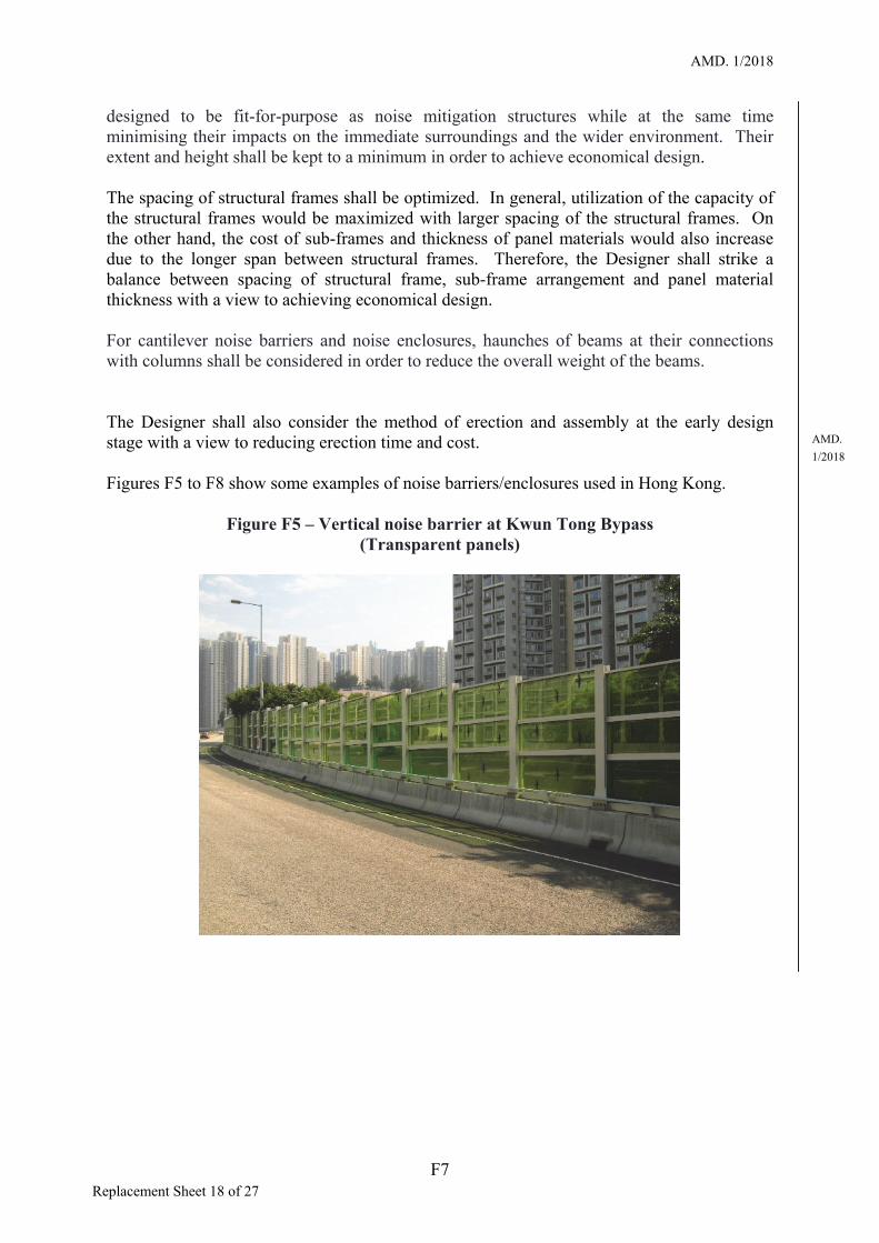
The adoption of greening measures shall follow the “Guidelines on Greening of Noise Barriers”. Figure F10 shows an example of noise enclosure with roof greening. Due consideration shall be given to adoption of greening measures as the additional heavy loading induced by landscaped decks and vegetation would increase the construction cost as well as the maintenance cost.
AMD. 1/2018
F11 Replacement Sheet 22 of 27
AMD. 1/2018
Figure F10 – Greening on the roof of a noise enclosure at Tuen Mun Road (Town Centre Section)
The Designer shall consult the maintenance authority in respect of the imposed loads on noise enclosure roofs for normal maintenance and repair works. In any case, the imposed loads shall not be less than the values given in Clause 3.7.3.4 of this Manual.
Where the panel material can absorb water, the wet weight should be considered. Structural frames shall be designed to support the wet weight of the panel material.
F.7 ACCIDENTAL ACTIONS CAUSED BY ROAD VEHICLES
In general, noise barriers/enclosures shall be set back sufficiently and protected by vehicle restraint systems of the appropriate containment level with full working width or supported on concrete rigid barriers of the appropriate containment level with full working width to reduce the vehicular impact actions.
In the design of noise barriers/enclosures against vehicular impact, the Designer shall formulate the strategy for the structure against accidental actions. The principles given in Clause 3.6.1 of this Manual and Clause 3.3 of BS EN 1991-1-7 shall be followed. In essence, a noise barrier/enclosure structure should be designed and constructed so that it is inherently robust and not unreasonably susceptible to the effects of accidents or misuse, and disproportionate collapse. The overall structural integrity of the structure shall be maintained following impact from vehicular impact, but local damage to a part of the support posts or other structural members can be accepted.
To improve the performance of noise barrier/enclosure structures against vehicular impact in the direction of normal travel, the support posts should be tied by one to two rows of structural members located at the top and near the mid-height of the support posts. This would increase the redundancy of the structure and reduce the resultant forces transferred to
AMD. 1/2018
F12 Replacement Sheet 23 of 27
AMD. 1/2018
the base of the support posts. As a result, the member sizes of the support posts would be reduced, especially for universal beam and universal column sections where the orientation of minor axis is usually perpendicular to the direction of normal travel.
F.8 DIRECTIONAL SIGNS
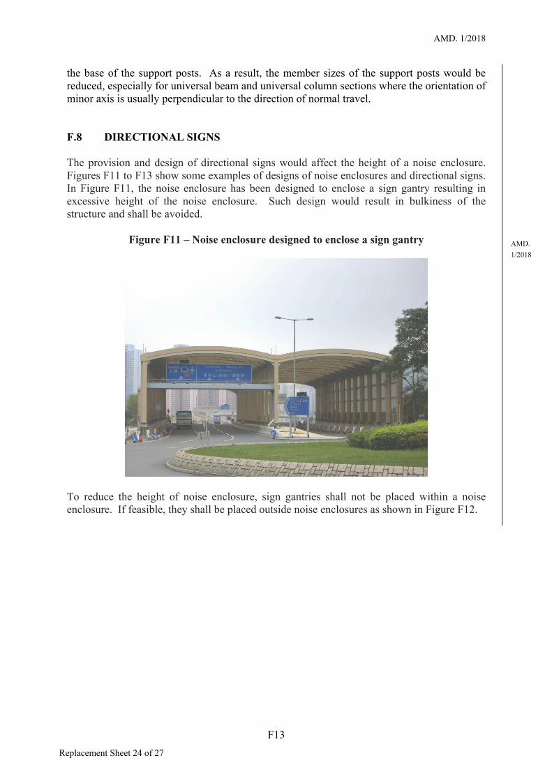
The provision and design of directional signs would affect the height of a noise enclosure. Figures F11 to F13 show some examples of designs of noise enclosures and directional signs. In Figure F11, the noise enclosure has been designed to enclose a sign gantry resulting in excessive height of the noise enclosure. Such design would result in bulkiness of the structure and shall be avoided.
Figure F11 – Noise enclosure designed to enclose a sign gantry
To reduce the height of noise enclosure, sign gantries shall not be placed within a noiseenclosure. If feasible, they shall be placed outside noise enclosures as shown in Figure F12.
AMD. 1/2018
F13
Replacement Sheet 24 of 27

AMD. 1/2018
Figure F12 – Sign gantry located outside a noise enclosure
AMD. For a directional sign to be placed within a noise enclosure, its shape shall be tailor-made to 1/2018 suit the roof profile of the noise enclosure and its dimensions shall be minimized to reduce the overall height of the noise enclosure. The directional sign shall be fixed to the roof structural members if practicable. Figure F13 shows an example of a directional sign designed to suit the profile of the noise enclosure roof and mounted to the roof structural members. The Transport Department shall be consulted on locations and dimensions of directional signs.
Figure F13 – Directional signs designed to suit the profile of the noise enclosure roof
F14 Replacement Sheet 25 of 27

AMD. 1/2018
F.9 AESTHETIC AND OTHER DESIGN CONSIDERATIONS
Similar to other forms of highway structures, the aesthetic appreciation of noise barriers/enclosures can be made from either the static viewpoint of observers away from the structures, or the dynamic viewpoint of motorists/users along the roadway. From the perspective of static appearance, the noise barriers/enclosures shall properly fit into the surroundings. The overall appearance of the structure shall not adversely affect the visual envelope of the spatial environment. From the motorists’ perspective, the noise barriers/enclosures shall not elicit a feeling of confinement, leading to driver discomfort. The guidelines given in “Guidelines on Design of Noise Barriers” and Clause 15.6.5 of this Manual shall be followed.
F.10 FIRE RESISTANCE AND EMERGENCY ACCESS
The guidelines on fire resistance and emergency access given in “Guidelines on Design of Noise Barriers” shall be followed. If transparent panels are used, the guidelines given in “Noise Barriers with Transparent Panels” shall also be followed.
F.11 HOLDING DEVICES AND CATCHING CONTRIVANCES
The risk associated with panels of noise barriers/enclosures falling onto vehicle/pedestrian paths upon impact by vehicles should be considered in the design. Holding devices shall be provided to prevent panels from falling off noise barrier/enclosures. Such devices shall be in form of wire ropes holding the four corners of each panel. If drilling on the panels is considered not appropriate (e.g. glass panels), the wires shall hold the sub-frames instead. In that case, the panels shall be properly glued to the sub-frames by sealant. For transparent panels, catching contrivances should be provided to prevent spread of panel fragments that could cause hazard to road users. The guidelines given in “Noise Barriers with Transparent Panels” shall be followed.
F.12 BIRD COLLISION
There were reported cases where birds collided onto noise barriers/enclosures with transparent panels causing bird mortality. As transparent panels appear invisible to birds or are reflective that mirror the facing landscape, birds are unable to recognize them as physical barriers. The Agriculture, Fisheries and Conservation Department recommends that transparent panels should be avoided as far as possible in the design of noise barriers/enclosures in areas with high bird density or for roads that cut across rural areas.
To alleviate the bird collision problem, the Designer should consider bird collision measures during the design stage. The guidelines given in “Noise Barriers with Transparent Panels” shall be followed.
AMD. 1/2018
F15 Replacement Sheet 26 of 27

AMD. 1/2018
F.13 GLARE
Noise barriers/enclosures with metallic and transparent materials can produce “glare” effects at certain incident angles of sunlight, causing nuisance to road users and nearby residents. Under some situations, the reflection of sunlight from slanting or horizontal panels would also cause nuisance to nearby residents. The Designer shall ensure that noise barriers/enclosures do not reflect light in such a way as to cause nuisance to road users and nearby residents, and the top surface of roof panels shall be non-glaring. If transparent panels are used, the guidelines given in “Noise Barriers with Transparent Panels” shall be followed.
The guidelines on lighting inside noise enclosures to avoid glare effects given in “Guidelines on Design of Noise Barriers” shall also be followed.
F.14 MAINTENANCE CONSIDERATIONS
The Designer should consider the need to stipulate in the contract that the supplier should specify the method and procedures for the future replacement of panels and/or cleansing of noise barrier/enclosure panels for agreement by the maintenance authority. Consideration shall be given at the early design stage to the provision of means of access to all locations and components of noise barriers/enclosures for inspection and maintenance. Such means of access may include walkways, working platforms, maintenance access openings, as appropriate. The guidelines given in “Guidelines on Design of Noise Barriers” and Chapter 16 of this Manual shall be followed. The maintenance authority shall also be consulted in this regard.
AMD. 1/2018
F16 Replacement Sheet 27 of 27