Embed Size (px)
Citation preview
Structured programming approach (CS-1001) 2020
Sir Padampat Singhania University Page 1
Chapter 1 Introduction to Computer, Algorithm and
Flowchart:
1.1 Introduction to computer
A Computer is an electronic device that is designed to work with Information. The
term computer is derived from the Latin term ‘computare’, this means to calculate or
programmable machine.
It is an electronic device for storing and processing data, typically in binary form,
according to instructions given to it in a variable program.
Computer cannot do anything without a Program
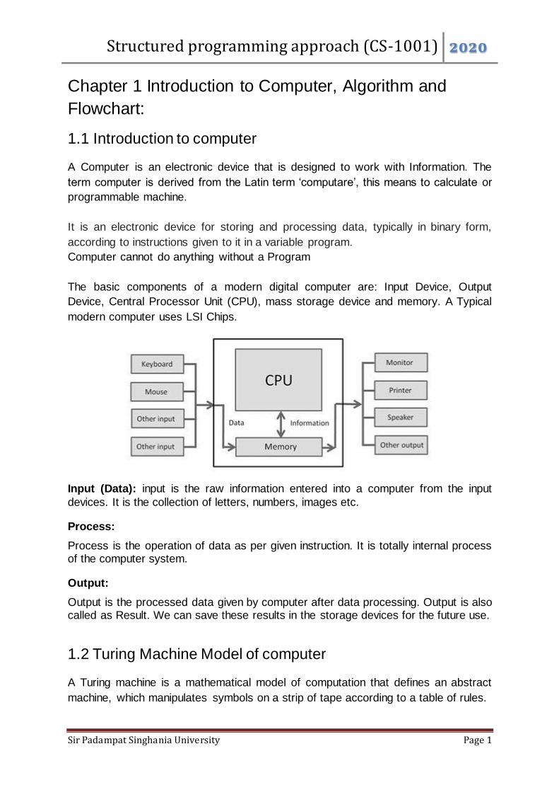
The basic components of a modern digital computer are: Input Device, Output
Device, Central Processor Unit (CPU), mass storage device and memory. A Typical
modern computer uses LSI Chips.
Input (Data): input is the raw information entered into a computer from the input
devices. It is the collection of letters, numbers, images etc.
Process: Process is the operation of data as per given instruction. It is totally internal process of the computer system.
Output: Output is the processed data given by computer after data processing. Output is also called as Result. We can save these results in the storage devices for the future use.
1.2 Turing Machine Model of computer
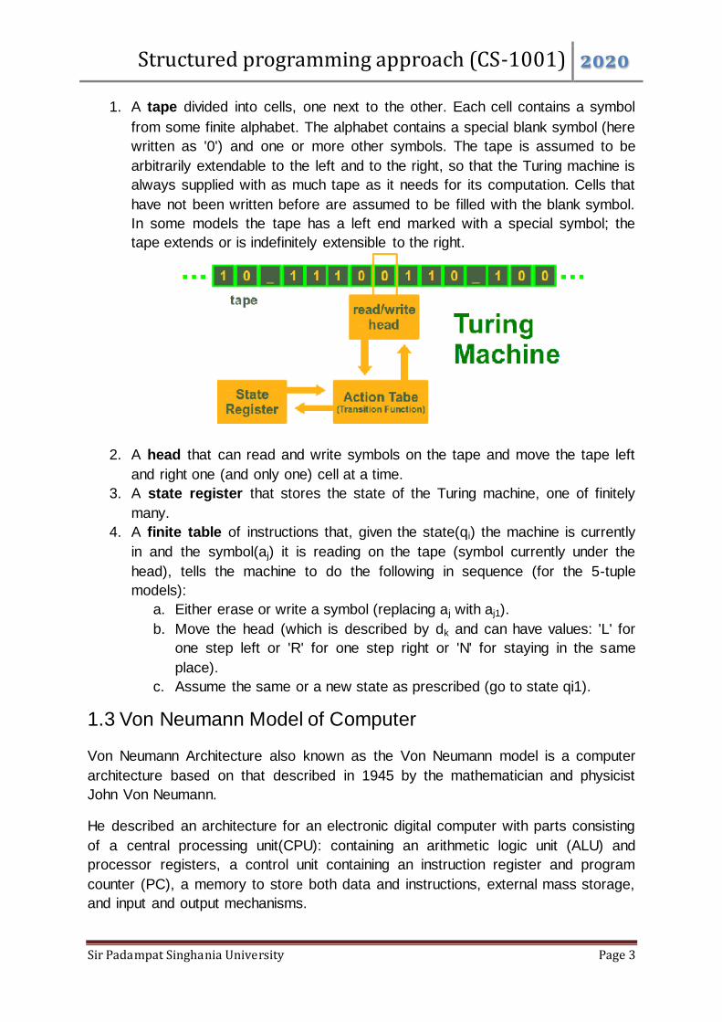
A Turing machine is a mathematical model of computation that defines an abstract
machine, which manipulates symbols on a strip of tape according to a table of rules.

Structured programming approach (CS-1001) 2020
Sir Padampat Singhania University Page 2
A Turing machine is a general example of a central processing unit (CPU) that
controls all data manipulation done by a computer, using sequential memory to store
data.
The machine operates on an infinite memory tape divided into discrete "cells". On
this tape are symbols, which the machine can read and write, one at a time, using a
tape head. The machine positions its "head" over a cell and "reads" or "scans" the
symbol there. Then, as per the symbol and its present place in a "finite table" of
user-specified instructions, the machine
(i) writes a symbol (e.g., a digit or a letter from a finite alphabet) in the
cell
(ii) either moves the tape one cell left or right then
(iii) Either proceeds to a subsequent instruction or halts the
computation.
The Turing machine was invented in 1936 by Alan Turing, who called it an "a-
machine" (automatic machine). The Turing machine mathematically models a
machine that mechanically operates on a tape.
A Turing machine consists of:
Structured programming approach (CS-1001) 2020
Sir Padampat Singhania University Page 3
1. A tape divided into cells, one next to the other. Each cell contains a symbol
from some finite alphabet. The alphabet contains a special blank symbol (here
written as '0') and one or more other symbols. The tape is assumed to be
arbitrarily extendable to the left and to the right, so that the Turing machine is
always supplied with as much tape as it needs for its computation. Cells that
have not been written before are assumed to be filled with the blank symbol.
In some models the tape has a left end marked with a special symbol; the
tape extends or is indefinitely extensible to the right.
2. A head that can read and write symbols on the tape and move the tape left
and right one (and only one) cell at a time.
3. A state register that stores the state of the Turing machine, one of finitely
many.
4. A finite table of instructions that, given the state(qi) the machine is currently
in and the symbol(aj) it is reading on the tape (symbol currently under the
head), tells the machine to do the following in sequence (for the 5-tuple
models):
a. Either erase or write a symbol (replacing aj with aj1).
b. Move the head (which is described by dk and can have values: 'L' for
one step left or 'R' for one step right or 'N' for staying in the same
place).
c. Assume the same or a new state as prescribed (go to state qi1).
1.3 Von Neumann Model of Computer
Von Neumann Architecture also known as the Von Neumann model is a computer
architecture based on that described in 1945 by the mathematician and physicist
John Von Neumann.
He described an architecture for an electronic digital computer with parts consisting
of a central processing unit(CPU): containing an arithmetic logic unit (ALU) and
processor registers, a control unit containing an instruction register and program
counter (PC), a memory to store both data and instructions, external mass storage,
and input and output mechanisms.

Structured programming approach (CS-1001) 2020
Sir Padampat Singhania University Page 4
Von Neumann architecture is based on the stored-program computer concept,
where instruction data and program data are stored in the same memory. The
meaning has evolved to be any stored-program computer in which an instruction
fetch and a data operation cannot occur at the same time because they share a
common bus.
The program is stored in the memory. The CPU fetches an instruction from the
memory at a time and executes it.
Modern Computer having three basic units:
1. The Central Processing Unit (CPU) 2. The Main Memory Unit 3. The Input/Output Device
Let’s consider them in details.
Control Unit –
The control unit controls the operation of the computer’s ALU, memory and
input/output devices, telling them how to respond to the program instructions it
has just read and interpreted from the memory unit.
The control unit also provides the timing and control signals required by other
computer components. A control unit (CU) handles all processor control signals.
Structured programming approach (CS-1001) 2020
Sir Padampat Singhania University Page 5
It directs all input and output flow, fetches code for instructions and controlling
how data moves around the system.
Arithmetic and Logic Unit (ALU) –
The arithmetic logic unit is that part of the CPU that handles all the calculations
the CPU may need, e.g. Addition, Subtraction, Comparisons. It performs
Logical Operations, Bit Shifting Operations, and Arithmetic Operation.
Main Memory Unit–
The memory unit consists of RAM, sometimes referred to as primary or main
memory. Unlike a hard drive (secondary memory); this memory is fast and also
directly accessible by the CPU. Loading data from permanent memory (hard
drive), into the faster and directly accessible temporary memory (RAM), allows
the CPU to operate much quicker.
CPU Registers–
The CPU contains the ALU, CU and a variety of registers. Registers are high
speed storage areas in the CPU. All data must be stored in a register before it
can be processed.
1. Accumulator: Stores the results of calculations made by ALU.
2. Program Counter (PC): Keeps track of the memory location of the next
instructions to be dealt with. The PC then passes this next address to Memory
Address Register (MAR).
3. Memory Address Register (MAR): It stores the memory locations of
instructions that need to be fetched from memory or stored into memory.
4. Memory Data Register (MDR): It stores instructions fetched from memory or
any data that is to be transferred to, and stored in, memory.
5. Current Instruction Register (CIR): It stores the most recently fetched
instructions while it is waiting to be coded and executed.
6. Instruction Buffer Register (IBR): The instruction that is not to be executed
immediately is placed in the instruction buffer register IBR.
Input/Output Devices – Program or data is read into main memory from
the input device or secondary storage under the control of CPU input
instruction. Output devices are used to output the information from a computer.
If some results are evaluated by computer and it is stored in the computer, then
with the help of output devices, we can present it to the user.
Buses – Data is transmitted from one part of a computer to another, connecting
all major internal components to the CPU and memory, by the means of Buses.
A standard CPU system bus is comprised of a control bus, data bus and
address bus.
1. Data Bus: It carries data among the memory unit, the I/O devices, and the
processor.
Structured programming approach (CS-1001) 2020
Sir Padampat Singhania University Page 6
2. Address Bus: It carries the address of data (not the actual data) between
memory and processor.
3. Control Bus: It carries control commands from the CPU (and status signals
from other devices) in order to control and coordinate all the activities within
the computer.
1.4 Introduction to Computer Memory:
A memory is just like a human brain which is used to store data and instructions.
Computer memory is the storage space in the computer, where data is to be
processed and instructions required for processing are stored.
The memory is divided into large number of small parts called cells. Each location or
cell has a unique address, which varies from zero to memory size minus one. For
example, if the computer has 64k words, then this memory unit has 64 * 1024 =
65536 memory locations. The address of these locations varies from 0 to 65535.
Memory is primarily of two types −
Primary Memory (Main Memory)
Secondary Memory
1.4.1 Primary Memory (Main Memory)
Primary memory is directly accessed by the CPU and it holds only those data
and instructions which are required to be processed by the CPU.
It has a limited capacity.
These memories are not as fast as registers.
Characteristics of Main Memory
These are semiconductor memories.
It is known as the main memory.
Usually volatile memory.
Data is lost in case power is switched off.
It is the working memory of the computer.
Faster than secondary memories.
A computer cannot run without the primary memory.
Classification of Primary Memory:
It is divided into two subcategories RAM and ROM.
1.4.1.1 RAM
RAM (Random Access Memory) is the internal memory of the CPU for storing data, program, and program result.

Structured programming approach (CS-1001) 2020
Sir Padampat Singhania University Page 7
Data in the RAM can be accessed randomly. Access time in RAM is independent of the address, that is, each storage location inside the memory is as easy to reach as other locations and takes the same amount of time.
RAM is small, both in terms of its physical size and in the amount of data it can hold.
It is very expensive.
RAM is volatile, i.e. data stored in it is lost when we switch off the computer or if there is a power failure.
RAM is of two types −
Static RAM (SRAM)
Dynamic RAM (DRAM)
Static RAM (SRAM)
The word static indicates that the memory retains its contents as long as power is
being supplied. However, data is lost when the power gets down due to volatile nature.
SRAM chips use a matrix of 6-transistors and no capacitors. Transistors do not require power to prevent leakage, so SRAM need not be refreshed on a regular basis.
There is extra space in the matrix, hence SRAM uses more space on chips than DRAM for the same amount of storage space, making the manufacturing costs higher.
SRAM is thus used as cache memory and has very fast access.
Characteristic of Static RAM Long life No need to refresh Faster Used as cache memory Large size Expensive High power consumption
Structured programming approach (CS-1001) 2020
Sir Padampat Singhania University Page 8
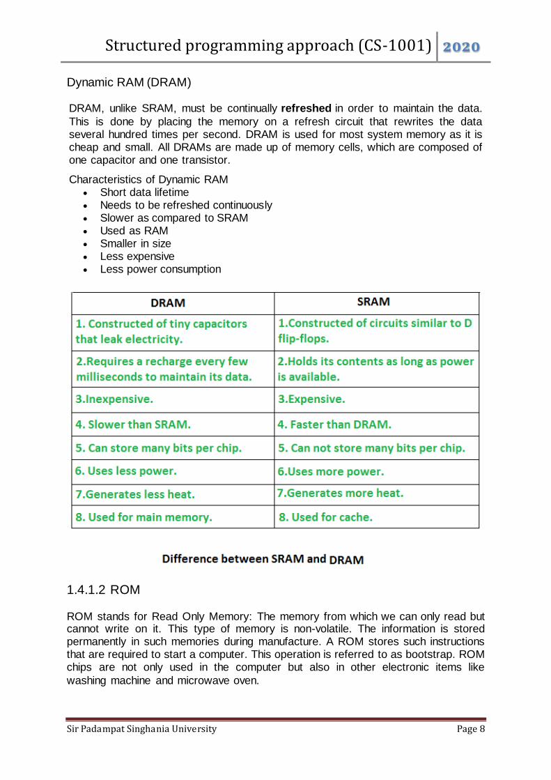
Dynamic RAM (DRAM)
DRAM, unlike SRAM, must be continually refreshed in order to maintain the data.
This is done by placing the memory on a refresh circuit that rewrites the data several hundred times per second. DRAM is used for most system memory as it is cheap and small. All DRAMs are made up of memory cells, which are composed of one capacitor and one transistor.
Characteristics of Dynamic RAM Short data lifetime Needs to be refreshed continuously Slower as compared to SRAM Used as RAM Smaller in size Less expensive Less power consumption
1.4.1.2 ROM
ROM stands for Read Only Memory: The memory from which we can only read but cannot write on it. This type of memory is non-volatile. The information is stored permanently in such memories during manufacture. A ROM stores such instructions that are required to start a computer. This operation is referred to as bootstrap. ROM chips are not only used in the computer but also in other electronic items like
washing machine and microwave oven.

Structured programming approach (CS-1001) 2020
Sir Padampat Singhania University Page 9
Let us now discuss the various types of ROMs and their characteristics.
1. MROM (Masked ROM)
The very first ROMs were hard-wired devices that contained a pre-
programmed set of data or instructions. These kinds of ROMs are known as
masked ROMs, which are inexpensive.
2. PROM (Programmable Read Only Memory)
PROM is read-only memory that can be modified only once by a user. The
user buys a blank PROM and enters the desired contents using a PROM
program. Inside the PROM chip, there are small fuses which are burnt open
during programming. It can be programmed only once and is not erasable.
3. EPROM (Erasable and Programmable Read Only Memory)
EPROM can be erased by exposing it to ultra-violet light for duration of up to
40 minutes. Usually, an EPROM eraser achieves this function. During
programming, an electrical charge is trapped in an insulated gate region. The
charge is retained for more than 10 years because the charge has no leakage
path.
For erasing this charge, ultra-violet light is passed through a quartz crystal
window (lid). This exposure to ultra-violet light dissipates the charge. During
normal use, the quartz lid is sealed with a sticker.
4. EEPROM (Electrically Erasable and Programmable Read Only Memory) EEPROM is programmed and erased electrically. It can be erased and
reprogrammed about ten thousand times. Both erasing and programming take
about 4 to 10 ms (millisecond). In EEPROM, any location can be selectively
erased and programmed. EEPROMs can be erased one byte at a time, rather
Structured programming approach (CS-1001) 2020
Sir Padampat Singhania University Page 10
than erasing the entire chip. Hence, the process of reprogramming is flexible
but slow.
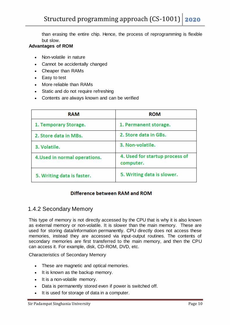
Advantages of ROM
Non-volatile in nature
Cannot be accidentally changed
Cheaper than RAMs
Easy to test
More reliable than RAMs
Static and do not require refreshing
Contents are always known and can be verified
1.4.2 Secondary Memory
This type of memory is not directly accessed by the CPU that is why it is also known as external memory or non-volatile. It is slower than the main memory. These are used for storing data/information permanently. CPU directly does not access these memories, instead they are accessed via input-output routines. The contents of secondary memories are first transferred to the main memory, and then the CPU can access it. For example, disk, CD-ROM, DVD, etc.
Characteristics of Secondary Memory
These are magnetic and optical memories.
It is known as the backup memory.
It is a non-volatile memory.
Data is permanently stored even if power is switched off.
It is used for storage of data in a computer.
Structured programming approach (CS-1001) 2020
Sir Padampat Singhania University Page 11
Computer may run without the secondary memory.
Slower than primary memories.
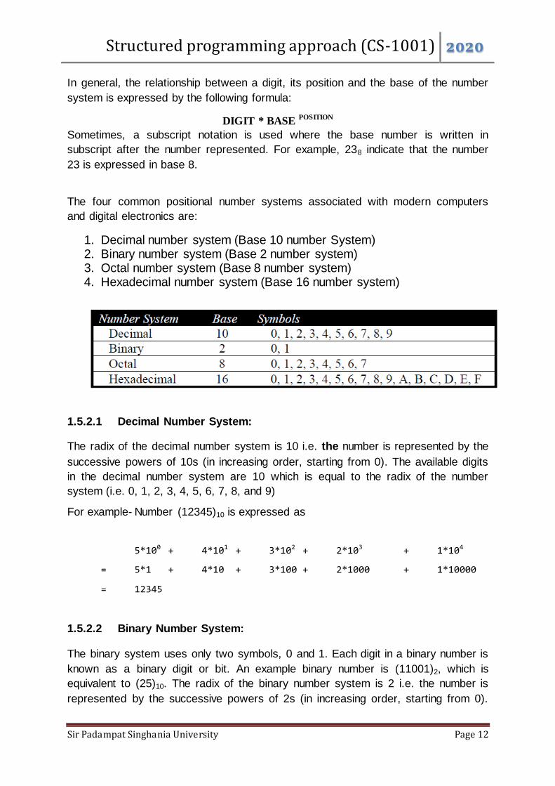
1.5 Introduction to Number System
The number system or the numeral system is the system of naming or representing
numbers. A number system is a collection of various symbols which are called digits.
Number systems are the technique to represent numbers in the computer system
architecture, every value that you are saving or getting into/from computer memory
has a defined number system.
Number systems are of two types:
1. Non-positional number system
2. Positional number system.
1.5.1 Non-Positional Number System
Initially the humans began counting on their fingers. For counting beyond ten, they
started using stones, pebbles or sticks to mark or indicated the value. This kind of
counting uses an additive approach or the Non-positional number.
In this system, we use symbols to indicate the value. Each symbol represents the
same value regardless of its position in a number, and to find value of a number, one
has to count the number of symbols present in the number. For example value one
can be represented with a single line, two with double lines, three with triple lines,
four with four lines and so on.
The disadvantage of using a non-positional number system is that it is very difficult to
perform arithmetic calculations with such a number system.
1.5.2 Positional Number System
In positional number system, there are only a few symbols called digits. A digit is a
numeral symbol, used in combinations, to represent numbers in positional numeral
systems. These symbols represent different values, depending upon the position
they occupy in a number. The value of any digit in a number can be determined by:
The digit
Its position in the number
The base of the number system
Base (Radix) of number system: The base or radix is usually the number of unique
digits, including zero that a positional numeral system uses to represent numbers.
Structured programming approach (CS-1001) 2020
Sir Padampat Singhania University Page 12
In general, the relationship between a digit, its position and the base of the number
system is expressed by the following formula:
DIGIT * BASE POSITION
Sometimes, a subscript notation is used where the base number is written in
subscript after the number represented. For example, 238 indicate that the number
23 is expressed in base 8.
The four common positional number systems associated with modern computers
and digital electronics are:
1. Decimal number system (Base 10 number System) 2. Binary number system (Base 2 number system) 3. Octal number system (Base 8 number system) 4. Hexadecimal number system (Base 16 number system)
1.5.2.1 Decimal Number System:
The radix of the decimal number system is 10 i.e. the number is represented by the
successive powers of 10s (in increasing order, starting from 0). The available digits
in the decimal number system are 10 which is equal to the radix of the number
system (i.e. 0, 1, 2, 3, 4, 5, 6, 7, 8, and 9)
For example- Number (12345)10 is expressed as
5*100 + 4*101 + 3*102 + 2*103 + 1*104
= 5*1 + 4*10 + 3*100 + 2*1000 + 1*10000
= 12345
1.5.2.2 Binary Number System:
The binary system uses only two symbols, 0 and 1. Each digit in a binary number is
known as a binary digit or bit. An example binary number is (11001)2, which is
equivalent to (25)10. The radix of the binary number system is 2 i.e. the number is
represented by the successive powers of 2s (in increasing order, starting from 0).
Structured programming approach (CS-1001) 2020
Sir Padampat Singhania University Page 13
The available digits in the binary number system are 2 which is equal to the radix of
the number system (i.e. 0, 1)
For example- Number (10101)2 is expressed as
1*20 + 0*21 + 1*22 + 0*23 + 1*24
= 1*1 + 0*2 + 1*4 + 0*8 + 1*16
= 1 + 0 + 4 + 0 + 16
= 21 (in decimal number system)
1.5.2.3 Octal Number System:
The radix of the octal number system is 8 i.e. the number is represented by the
successive powers of 8s (in increasing order, starting from 0). The available digits in
the octal number system are 8 which is equal to the radix of the number system (i.e.
0, 1, 2, 3, 4, 5, 6, and 7)
For example- Number (12345)8 is expressed as
5*80 + 4*81 + 3*82 + 2*83 + 1*84
= 5*1 + 4*8 + 3*64 + 2*512 + 1*4096
= 5 + 32 + 192 + 1024 + 4096
= 5349 (in decimal number system)
1.5.2.4 Hex Decimal Number System:
The radix of the hex decimal number system is 16 i.e. the number is represented by
the successive powers of 16s (in increasing order, starting from 0). The available
digits in the octal number system are 16 which is equal to the radix of the number
system (i.e. 0, 1, 2, 3, 4, 5, 6, 7, 8, 9, A, B, C, D, E, and F ) where the equivalent no.
of the alphabets are as follows:
A = 10
B = 11
C = 12
D = 13
E = 14
F = 15
For example- Number (12F) 16 is expressed as
15*160 + 2*161 + 1*162
= 15*1 + 2*16 + 1*256

Structured programming approach (CS-1001) 2020
Sir Padampat Singhania University Page 14
= 15 + 32 + 256
= 303 (in decimal number system)
1.5.3 Conversion of Number System
1.5.3.1 Decimal to Binary
To convert decimal number to binary, continually divide the number by 2 until the
quotient is zero. The remainders give the binary representation of the number in
reverse order. The remainder being either 0 or 1 forms the binary number with the
last remainder representing the most significant bit.
Example- (14)10 = (1110)2 Remainder
2) 14 0
2) 7 1
2) 3 1
2) 1 1 Read in the Reverse order
0
Example- convert (52)10 into (?)2
52/2 = 26 remainder 0 LSB
26/2 = 13 remainder 0
13/2 = 6 remainder 1
6/2 = 3 remainder 0
3/2 = 1 remainder 1
1/2 = 0 remainder 1 MSB
The answer, therefore, is (110100)2
1.5.3.2 Decimal to Octal
To convert decimal number to octal, continually divide the number by 8 until
the quotient is zero. The remainder being any number from 0, 1, 2, 3, 4, 5, 6,
or 7 forms the octal number with the last remainder representing the most
significant bit. The remainders give the octal representation of the number in
reverse order.
Example- (23)10 = (27)8
Remainder
8) 23 7
8) 2 2 Read in the Reverse order
0
Structured programming approach (CS-1001) 2020
Sir Padampat Singhania University Page 15
Example- convert (5819)10 into (?)8
5819/8 = 727 remainder 3 LSB
727/8 = 90 remainder 7
90/8 = 11 remainder 2
11/8 = 1 remainder 3
1/8 = 0 remainder 1 MSB
The answer, therefore, is (13273)8
1.5.3.3 Decimal to Hexadecimal
To convert decimal number to hexadecimal, continually divide the number by
16 until the quotient is zero. The remainder being any number from 0, 1, 2,
3, 4, 5, 6, 7, 8, 9, 10, 11, 12, 13, 14, or 15 where the numbers 10, 11, 12, 13,
14, and 15 representing the alphabets A, B, C, D, E, and F respectively forms
the hex decimal number with the last remainder representing the most
significant bit. The remainders give the hexadecimal representation of the
number in reverse order.
Example- (46)10 = (2E) 16
Remainder
16) 46 14 = E
16) 2 2 = 2 Read in the Reverse order
0
Example- converts (3409)10 into (?)8
3409/16 = 213 remainder 1 LSB
213/16 = 13 remainder 5
13/16 = 0 remainder 13 MSB
The answer, therefore, is (D51)16
1.5.3.4 Binary to Decimal
To convert binary number to decimal, multiply the binary digits by the correct power
of 2 from LSB to MSB, and sum them.
Example: (1110)2 = ( ? )10
(1110)2 = 1 x 23 + 1 x 22 + 1 x 21 + 0 x 20
= 1 x 8 + 1 x 4 + 1 x 2 + 0 x 1
= 8 + 4 + 2
= (14)10
1.5.3.5 Binary to Hexadecimal

Structured programming approach (CS-1001) 2020
Sir Padampat Singhania University Page 16
To convert binary number to hexadecimal, binary digits are grouped into fours
starting from the right hand end of the bit pattern and padding the leftmost group with
zeros to make a pattern of four (if necessary). Each group of four is coded as a
single hexadecimal digit similar to converting 4 binary digits to decimal.
Example: (101010) 2 = (2A)16
0010 1010
2 10 (A)
1.5.3.6 Binary to Octal
To convert binary number to octal, binary digits are grouped into threes starting from
the right hand end of the bit pattern and padding the leftmost group with zeros to
make a pattern of three (if necessary). Each group of three is coded as a single octal
digit similar to converting 3 binary digits to decimal.
Example: (11010)2 = (32)8
011 010
3 2
1.5.3.7 Octal to Decimal
To convert octal number to decimal, multiply the octal digits by the correct power of 8
and sum them.
Example- Number (12345)8 is expressed as
5*80 + 4*81 + 3*82 + 2*83 + 1*84
= 5*1 + 4*8 + 3*64 + 2*512 + 1*4096
= 5 + 32 + 192 + 1024 + 4096
= 5349 (in decimal number system)
1.5.3.8 Octal to Binary
To convert octal number to binary, each octal digit is expanded into the equivalent 3
binary digits.
Example: (32)8 = (011 010)2
(32)8 = 3 2
011 010
1.5.3.9 Hexadecimal to Binary
To convert hexadecimal number to binary, each hexadecimal digit is expanded into
the equivalent 4 binary digits.
Example: (2A) 16 = (0010 1010)2
Structured programming approach (CS-1001) 2020
Sir Padampat Singhania University Page 17
(2A)16 = 2 A
0010 1010
1.5.3.10 Hex Decimal to Decimal:
To convert hexadecimal number to decimal, multiply the hexadecimal digits by
the correct power of 16 and sum them.
Example: (2E) 16 = (46) 10
(2E) 16= 2 x 161 + 14 x 160
= 2 x 16 + 14 x 1
= 32 + 14
= 4610
Example: Number (12F) 16 is expressed as
15*160 + 2*161 + 1*162
= 15*1 + 2*16 + 1*256
= 15 + 32 + 256
= 303 (in decimal number system)
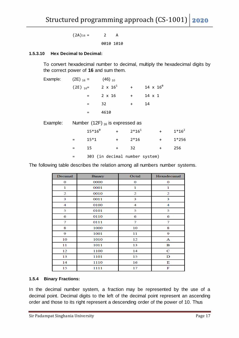
The following table describes the relation among all numbers number systems.
1.5.4 Binary Fractions:
In the decimal number system, a fraction may be represented by the use of a
decimal point. Decimal digits to the left of the decimal point represent an ascending
order and those to its right represent a descending order of the power of 10. Thus

Structured programming approach (CS-1001) 2020
Sir Padampat Singhania University Page 18
(0.1)10 = 10-1 = 1/10
(0.01)10 = 10-2 = 1/102 and so on,
And similarly, for the binary representation of fractions. A binary point is used to
represent a descending order of negative powers of the base 2 (which is equal of the
radix of the binary number system). Hence
(0.1)2 = 2-1 = ½ and
(0.01)2 = 2-2 = 1/22
The same method will be followed to handle the octal and hex decimal fractions. An
octal point is used to represent a descending order of negative powers of the base 8
(which is equal of the radix of the octal number system). And similarly, a Hex decimal
point is used to represent a descending order of negative powers of the base 16
(which is equal of the radix of the hex decimal number system).
1.5.5 Binary Arithmetic:
We can perform various arithmetic operations over binary numbers as we do with
decimal numbers like addition, subtraction, multiplication and division. Basic rules for
all these operations are as follows.
1.5.5.1 Binary Addition:
The following are the basic rules for binary addition:

Structured programming approach (CS-1001) 2020
Sir Padampat Singhania University Page 19
0 + 0 = 0
0 + 1 = 1
1 + 0 = 1
1 + 1 = 0, carry 1.
Example: (11001)2 + (11011)2= (?)2
1 1 0 0 1
+ 1 1 0 1 1
_______________________________________
1 1 0 1 0 0 Sum
_______________________________________
1 1 1 1 Carry
Where more than two binary numbers are added together, the carry may involve
numbers other than 1. For instance while
1 + 1 = 0, carry 1
1 + 1 + 1 = 1, carry 1
1 + 1 + 1 + 1 = 0, carry 2 and so on.
Example- (10110) 2 + (11101) 2+ (11101) 2 = (?)2
1 0 1 1 0
1 1 1 0 1
+ 1 1 1 0 1
________________________________________
1 0 1 0 0 0 0 Sum
_________________________________________
1 2 2 2 1 1 Carry
1.5.5.2 Binary Subtraction
The following are the basic rules for binary subtraction:

Structured programming approach (CS-1001) 2020
Sir Padampat Singhania University Page 20
0 – 0 = 0
1 – 0 = 1
1 – 1 = 0
0 – 1 = 1, borrow 1
Example- Subtract (0101) 2 from (1111) 2= (?)2
1 1 1 1
- 0 1 0 1
_________________________________
1 0 1 0 Result
1.5.5.3 Binary Multiplication
The following are the basic rules for binary multiplication:
0 * 0 = 0
0 * 1 = 0
1 * 0 = 0
1 * 1 = 1
Example- Multiply 1110 by 1101
Multiplicand 1 1 1 0
Multiplier x 1 1 0 1
_____________________________________________________
1 1 1 0
0 0 0 0
1 1 1 0
1 1 1 0
_______________________________________________________
1 0 1 1 0 1 1 0
Product
Example- Multiply 1100 by 1010
Multiplicand 1 1 0 0
Structured programming approach (CS-1001) 2020
Sir Padampat Singhania University Page 21
Multiplier x 1 0 1 0
0 0 0 0
1 1 0 0
0 0 0 0
1 1 0 0
1 1 1 1 0 0 0
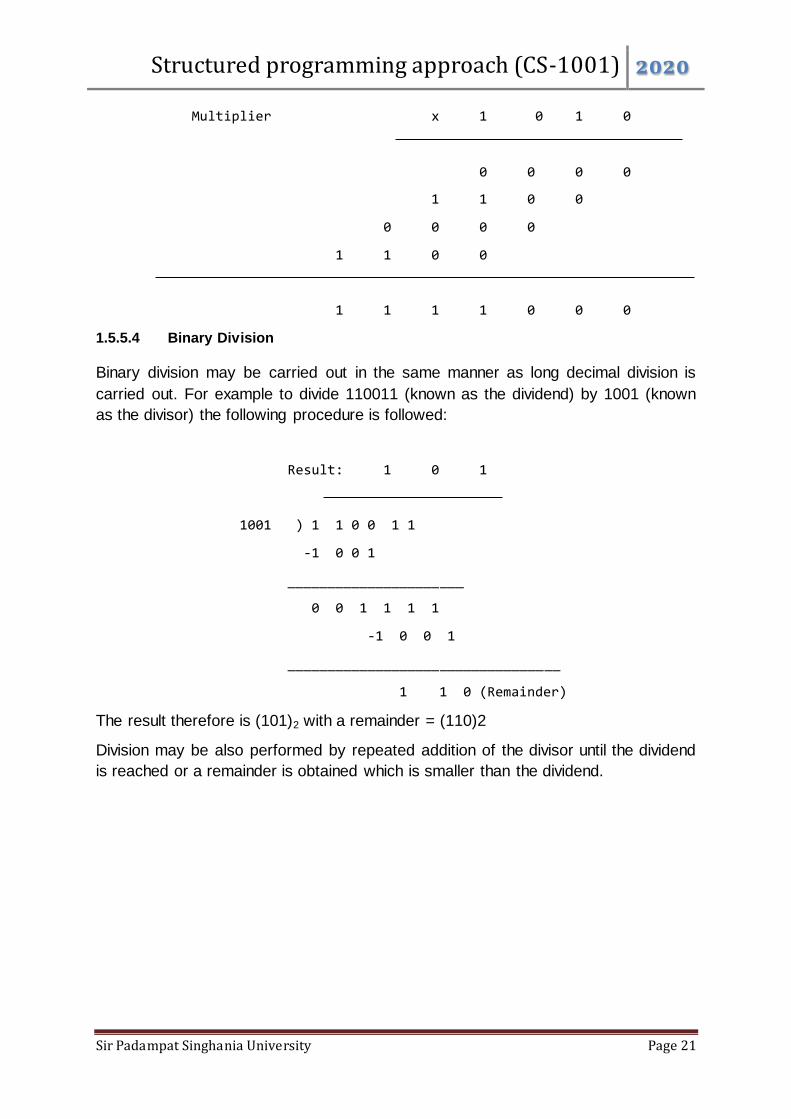
1.5.5.4 Binary Division
Binary division may be carried out in the same manner as long decimal division is
carried out. For example to divide 110011 (known as the dividend) by 1001 (known
as the divisor) the following procedure is followed:
Result: 1 0 1
1001 ) 1 1 0 0 1 1
-1 0 0 1
______________________
0 0 1 1 1 1
-1 0 0 1
__________________________________
1 1 0 (Remainder)
The result therefore is (101)2 with a remainder = (110)2
Division may be also performed by repeated addition of the divisor until the dividend
is reached or a remainder is obtained which is smaller than the dividend.

Structured programming approach (CS-1001) 2020
Sir Padampat Singhania University Page 22
1.6 Introduction to Operating System
An operating system acts as an interface between the user of a computer and
computer hardware. it is the one program running at all times on the computer
(usually called the kernel), with all else being application programs.
The purpose of an operating system is to provide an environment in which a user
can execute programs in a convenient and efficient manner.
An operating system is a system program that controls the execution of application
programs and acts as an interface between the user of a computer and the computer
hardware.
An Operating System is a resource allocator because It controls and allocates
computing System’s resources and services among the various user and tasks. A
System having different resources such as memory, processors, devices, and
information.
Figure : Conceptual view of operating system
1.6.1 Components of Operating System.
An operating system is a large and complex system that can only be created by
partitioning into small pieces. There are different components of operating system for
controlling and managing different tasks in system.
1. Process Management
2. File Management
3. Main Memory management
4. Secondary-Storage Management
5. Security Management
6. I/O Device Management
7. Network Management
Structured programming approach (CS-1001) 2020
Sir Padampat Singhania University Page 23
1.6.1.1 Process Management
The process management component is a procedure for managing the many
processes that are running simultaneously on the operating system. Every software
application program has one or more processes associated with them when they are
running.
The following are functions of process management.
Process creation and deletion.
Suspension and resumption.
Synchronization process
Communication process
1.6.1.2 File Management
A file is a set of related information which is should define by its creator. It commonly
represents programs, both source and object forms, and data. Data files can be
numeric, alphabetic, or alphanumeric.
The operating system has the following important given activities in connections with
file management:
File and directory creation and deletion.
For manipulating files and directories.
Mapping files onto secondary storage.
Backup files on stable storage media.
1.6.1.3 Main memory Management
Main Memory is a large array of storage or bytes, which has an address. The
memory management process is conducted by using a sequence of reads or writes
of specific memory addresses.
An Operating System performs the following functions for Memory Management:
It helps you to keep track of primary memory.
Determine what part of it are in use by whom, what part is not in use.
In a multiprogramming system, the OS takes a decision about which process
will get Memory and how much.
Allocates the memory when a process requests
It also de-allocates the Memory when a process no longer requires or has
been terminated.

Structured programming approach (CS-1001) 2020
Sir Padampat Singhania University Page 24
1.6.1.4 Secondary Storage Management
This Memory of the computer is very small to store all data and programs
permanently. The computer system offers secondary storage to back up the main
Memory.
Here, are major functions of secondary storage management in OS:
Storage allocation
Free space management
Disk scheduling
1.6.1.5 Security Management
The various processes in an operating system need to be secured from each other's
activities.
Here, are some other important activities of OS:
The user's program can't execute I/O operations directly. The operating
system should provide some medium to perform this.
OS checks the capability of the program to read, write, create, and delete
files.
OS facilitates an exchange of information between processes executing on
the same or different systems.
OS components help you to makes sure that you get the correct computing by
detecting errors in the CPU and memory hardware.
1.6.1.6 I/O Device Management
One of the important use of an operating system that helps you to hide the variations
of specific hardware devices from the user.
It offers buffer caching system
It provides general device driver code
It provides drivers for particular hardware devices.
I/O helps you to knows the individualities of a specific device.
1.6.1.7 Network Management
Network management is the process of administering and managing computer
networks. It includes performance management, fault analysis, provisioning of
networks, and maintaining the quality of service.

Structured programming approach (CS-1001) 2020
Sir Padampat Singhania University Page 25
1.7 Problem solving Approach
Can you think of a day in your life which goes without problem solving? Answer to
this question is of course, No. In our life we are bound to solve problems. In our day
to day activity such as purchasing something from a general store and making
payments, depositing fee in school, or withdrawing money from bank account. All
these activities involve some kind of problem solving. It can be said that whatever
activity a human being or machine do for achieving a specified objective comes
under problem solving. To make it clearer, let us see some other examples.
Example1: If you are watching a news channel on your TV and you want to change
it to a sports channel, you need to do something i.e. move to that channel by
pressing that channel number on your remote. This is a kind of problem solving.
Example 2: One Monday morning, a student is ready to go to school but yet he/she
has not picked up those books and copies which are required as per timetable. So
here picking up books and copies as per timetable is a kind of problem solving.
Example 3: If someone asks to you, what is time now? So seeing time in your watch
and telling him is also a kind of problem solving.
Example 4: Some students in a class plan to go on picnic and decide to share the
expenses among them. So calculating total expenses and the amount an individual
have to give for picnic is also a kind of problem solving.
If you can solve a given problem then you can also write an algorithm for it. In next
section we will learn what an algorithm is?
1.8 Introduction to Algorithm
Algorithm can be defined as: “A sequence of activities to be processed for getting
desired output from a given input.”
Webopedia defines an algorithm as: “A formula or set of steps for solving a particular
problem. To be an algorithm, a set of rules must be unambiguous and have a clear
stopping point”. There may be more than one way to solve a problem, so there may
be more than one algorithm for a problem.
Structured programming approach (CS-1001) 2020
Sir Padampat Singhania University Page 26
Now, if we take definition of algorithm as: “A sequence of activities to be processed
for getting desired output from a given input.” Then we can say that:
1. Getting specified output is essential after algorithm is executed.
2. One will get output only if algorithm stops after finite time.
3. Activities in an algorithm to be clearly defined in other words for it to be
unambiguous.
Before writing an algorithm for a problem, one should find out what is/are the inputs
to the algorithm and what is/are expected output after running the algorithm.
Example of Algorithm
Problem 1: Find the area of a Circle of radius r.
Inputs to the algorithm:
Radius r of the Circle.
Expected output:
Area of the Circle
Algorithm:
Step1: Read\input the Radius r of the Circle
Step2: Area=PI*r*r // calculation of area
Step3: Print Area
Problem2: Write an algorithm to read two numbers and find their sum.
Inputs to the algorithm:
First num1.
Second num2.
Expected output:
Sum of the two numbers.
Algorithm:
Step1: Start
Step2: Read\input the first num1.
Step3: Read\input the second num2.
Step4: Sum= num1+num2 // calculation of sum
Step5: Print Sum
Step6: End

Structured programming approach (CS-1001) 2020
Sir Padampat Singhania University Page 27
Problem 3: Convert temperature Fahrenheit to Celsius
Inputs to the algorithm:
Temperature in Fahrenheit
Expected output:
Temperature in Celsius
Algorithm:
Step1: Start
Step 2: Read Temperature in Fahrenheit F
Step 3: C = 5/9*(F32)
Step 4: Print Temperature in Celsius: C
Step5: End
1.8.1 Properties of the algorithms
Donald Ervin Knuth has given a list of five properties for a,algorithm, these properties
are:
Finiteness: An algorithm must always terminate after a finite number of
steps. It means after every step one reach closer to solution of the problem
and after a finite number of steps algorithm reaches to an end point.
Definiteness: Each step of an algorithm must be precisely defined. It is done
by well thought actions to be performed at each step of the algorithm. Also the
actions are defined unambiguously for each activity in the algorithm.
Input: Any operation you perform need some beginning value/quantities
associated with different activities in the operation. So the value/quantities are
given to the algorithm before it begins.
Output: One always expects output/result (expected value/quantities) in
terms of output from an algorithm. The result may be obtained at different
stages of the algorithm. If some result is from the intermediate stage of the
operation then it is known as intermediate result and result obtained at the
end of algorithm is known as end result. The output is expected
value/quantities always have a specified relation to the inputs.
Effectiveness: Algorithms to be developed/written using basic operations.
Actually operations should be basic, so that even they can in principle be
done exactly and in a finite amount of time by a person, by using paper and
pencil only.
Structured programming approach (CS-1001) 2020
Sir Padampat Singhania University Page 28
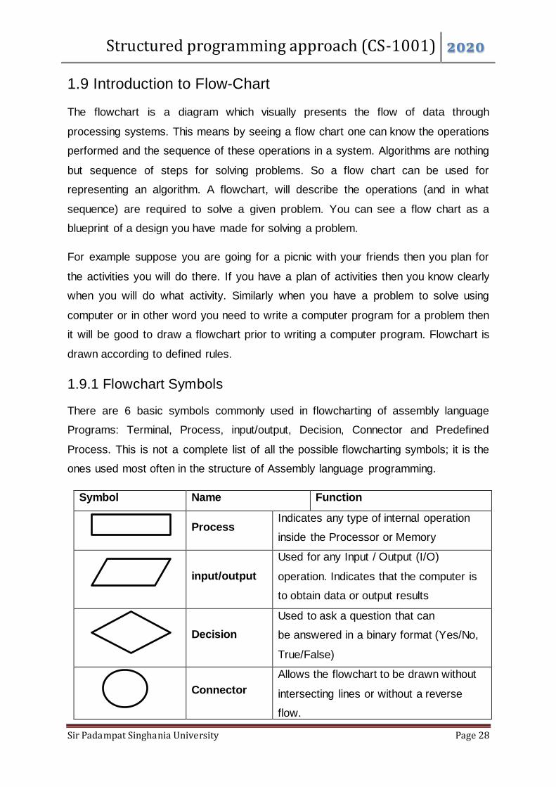
1.9 Introduction to Flow-Chart
The flowchart is a diagram which visually presents the flow of data through
processing systems. This means by seeing a flow chart one can know the operations
performed and the sequence of these operations in a system. Algorithms are nothing
but sequence of steps for solving problems. So a flow chart can be used for
representing an algorithm. A flowchart, will describe the operations (and in what
sequence) are required to solve a given problem. You can see a flow chart as a
blueprint of a design you have made for solving a problem.
For example suppose you are going for a picnic with your friends then you plan for
the activities you will do there. If you have a plan of activities then you know clearly
when you will do what activity. Similarly when you have a problem to solve using
computer or in other word you need to write a computer program for a problem then
it will be good to draw a flowchart prior to writing a computer program. Flowchart is
drawn according to defined rules.
1.9.1 Flowchart Symbols
There are 6 basic symbols commonly used in flowcharting of assembly language
Programs: Terminal, Process, input/output, Decision, Connector and Predefined
Process. This is not a complete list of all the possible flowcharting symbols; it is the
ones used most often in the structure of Assembly language programming.
Symbol Name Function
Process
Indicates any type of internal operation
inside the Processor or Memory
input/output
Used for any Input / Output (I/O)
operation. Indicates that the computer is
to obtain data or output results
Decision
Used to ask a question that can
be answered in a binary format (Yes/No,
True/False)
Connector
Allows the flowchart to be drawn without
intersecting lines or without a reverse
flow.
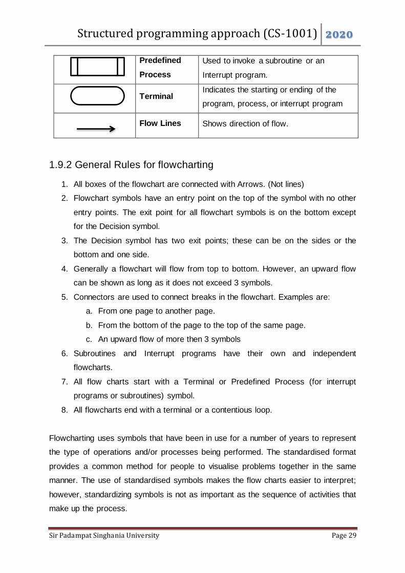
Structured programming approach (CS-1001) 2020
Sir Padampat Singhania University Page 29
Predefined
Process
Used to invoke a subroutine or an
Interrupt program.
Terminal
Indicates the starting or ending of the
program, process, or interrupt program
Flow Lines Shows direction of flow.
1.9.2 General Rules for flowcharting
1. All boxes of the flowchart are connected with Arrows. (Not lines)
2. Flowchart symbols have an entry point on the top of the symbol with no other
entry points. The exit point for all flowchart symbols is on the bottom except
for the Decision symbol.
3. The Decision symbol has two exit points; these can be on the sides or the
bottom and one side.
4. Generally a flowchart will flow from top to bottom. However, an upward flow
can be shown as long as it does not exceed 3 symbols.
5. Connectors are used to connect breaks in the flowchart. Examples are:
a. From one page to another page.
b. From the bottom of the page to the top of the same page.
c. An upward flow of more then 3 symbols
6. Subroutines and Interrupt programs have their own and independent
flowcharts.
7. All flow charts start with a Terminal or Predefined Process (for interrupt
programs or subroutines) symbol.
8. All flowcharts end with a terminal or a contentious loop.
Flowcharting uses symbols that have been in use for a number of years to represent
the type of operations and/or processes being performed. The standardised format
provides a common method for people to visualise problems together in the same
manner. The use of standardised symbols makes the flow charts easier to interpret;
however, standardizing symbols is not as important as the sequence of activities that
make up the process.

Structured programming approach (CS-1001) 2020
Sir Padampat Singhania University Page 30
Some examples of Flowcharts
Problem1: Find the area of a circle of radius r.
Problem 2: Convert temperature Fahrenheit to Celsius.
Start
Read
radius R
Calculate
Area=3.14*R*R
End
Area
Start
Read
F
Calculate
C=5/9*(F-32)
End
C
Structured programming approach (CS-1001) 2020
Sir Padampat Singhania University Page 31
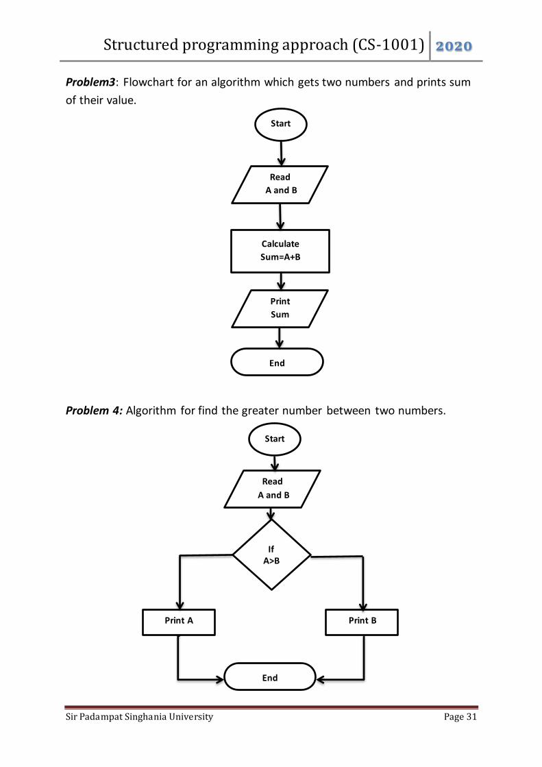
Problem3: Flowchart for an algorithm which gets two numbers and prints sum
of their value.
Problem 4: Algorithm for find the greater number between two numbers.
Start
Read
A and B
Calculate
Sum=A+B
End
Sum
Start
Read
A and B
If A>B
Print A Print B
End
Structured programming approach (CS-1001) 2020
Sir Padampat Singhania University Page 32
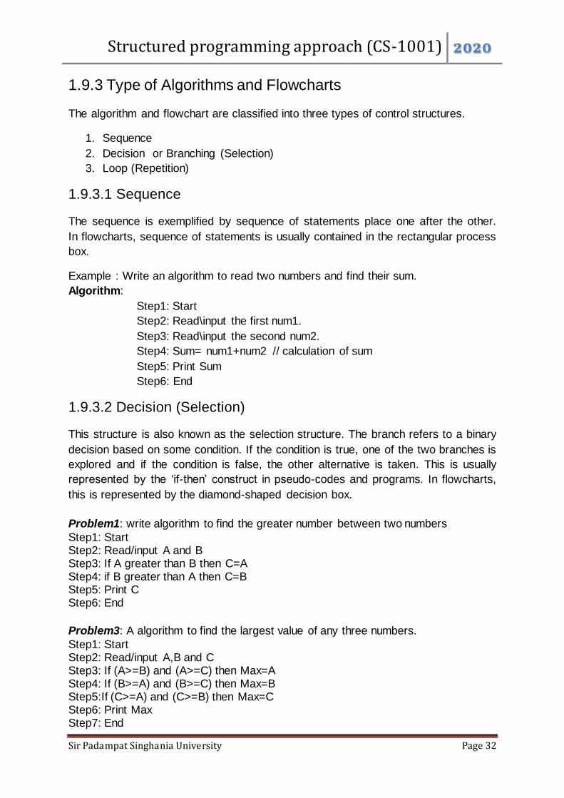
1.9.3 Type of Algorithms and Flowcharts
The algorithm and flowchart are classified into three types of control structures.
1. Sequence
2. Decision or Branching (Selection)
3. Loop (Repetition)
1.9.3.1 Sequence
The sequence is exemplified by sequence of statements place one after the other.
In flowcharts, sequence of statements is usually contained in the rectangular process
box.
Example : Write an algorithm to read two numbers and find their sum.
Algorithm:
Step1: Start
Step2: Read\input the first num1.
Step3: Read\input the second num2.
Step4: Sum= num1+num2 // calculation of sum
Step5: Print Sum
Step6: End
1.9.3.2 Decision (Selection)
This structure is also known as the selection structure. The branch refers to a binary
decision based on some condition. If the condition is true, one of the two branches is
explored and if the condition is false, the other alternative is taken. This is usually
represented by the ‘if-then’ construct in pseudo-codes and programs. In flowcharts,
this is represented by the diamond-shaped decision box.
Problem1: write algorithm to find the greater number between two numbers
Step1: Start Step2: Read/input A and B Step3: If A greater than B then C=A Step4: if B greater than A then C=B Step5: Print C Step6: End
Problem3: A algorithm to find the largest value of any three numbers.
Step1: Start Step2: Read/input A,B and C Step3: If (A>=B) and (A>=C) then Max=A Step4: If (B>=A) and (B>=C) then Max=B Step5:If (C>=A) and (C>=B) then Max=C Step6: Print Max Step7: End

Structured programming approach (CS-1001) 2020
Sir Padampat Singhania University Page 33
1.9.3.3 Loop (Repetition)
The loop is also known as the repetition structure. The loop allows a statement or a
sequence of statements to be repeatedly executed based on some loop condition.
In the flowcharts, a back arrow hints the presence of a loop. A trip around the loop is
known as iteration. You must ensure that the condition for the termination of the
looping must be satisfied after some finite number of iterations, otherwise it ends up
as an infinite loop.
Examples:
Problem1: An algorithm to calculate even numbers between 0 and 99
1. Start
2. I ← 0
3. Write I in standard output
4. I ← I+2
5. If (I <=98) then go to line 3
6. End
Problem2: Design an algorithm which gets a natural value, n, as its input and
calculates odd numbers equal or less than n. Then write them in the standard output:
1. Start
2. Read n
3. I ← 1
4. Write I
5. I ← I + 2
6. If ( I <= n) then go to line 4
7. End
Problem3: Design an algorithm which generates even numbers between 1000 and
2000 and then prints them in the standard output. It should also print total sum:
1. Start
2. I ← 1000 and S ← 0
3. Write I
4. S ← S + I
5. I ← I + 2
6. If (I <= 2000) then go to line 3
else go to line 7
7. Write S
8. End