Embed Size (px)
Citation preview
Structured meshes and reliable CFD simulations: TwinMesh for positive displacement machines Dipl.-Ing. Jan Hesse, CFX Berlin Software GmbH, Berlin
Dr. Andreas Spille-Kohoff, CFX Berlin Software GmbH, Berlin Dr. Jan Hauser, GHH RAND Schraubenkompressoren GmbH Dipl.-Ing. Philipp Schulze-Beckinghausen, GHH RAND Schraubenkompressoren GmbH
Abstract
Computational Fluid Dynamics (CFD) simulations have promising potential to become an
important part in the development process of positive displacement (PD) machines. CFD
delivers deep insights into the flow and thermodynamic behaviour of PD machines. However,
the numerical simulation of such machines is more complex compared to dynamic pumps
like turbines or fans. The fluid transport in size-changing chambers with very small
clearances between the lobes, and between rotors and casing, demands complex meshes
that change with each time step. Additionally, the losses due to leakage flow and cavitation
effects need high-quality meshes so that automatic remeshing is almost impossible.
TwinMesh is a novel software developed by CFX Berlin Software GmbH, which generates
high-quality hexahedral meshes for each time step automatically to represent the
continuously changing fluid volumes of the inter-lobe chambers. TwinMesh can be used for
external and internal gear pumps, rotary lobe pumps and screw compressors with arbitrary
lobe shapes and twisted or straight rotors. The meshes consist of near-orthogonal
hexahedral elements with accurate boundary layer resolution. The meshes are generated in
advance and read in at run-time from ANSYS CFD by special routines. The mesh topology
remains the same and therefore, no interpolation or solver restarts are necessary thus,
ensuring a fast and reliable CFD simulation.
Simulations were conducted for screw compressors with complex real gas properties as well
as gear pumps with cavitation (multiphase), non-constant viscosities (non-Newtonian fluid)
and particle transport. The usage of hybrid scale-resolving turbulence models like DES
(detached-eddy simulation) and SAS (scale-adaptive simulation), especially for vortex
cavitation prediction, as well as multiphase simulation for oil-injected screw compressors is
scheduled for ongoing projects.
1. Introduction
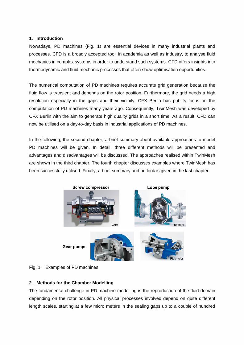
Nowadays, PD machines (Fig. 1) are essential devices in many industrial plants and
processes. CFD is a broadly accepted tool, in academia as well as industry, to analyse fluid
mechanics in complex systems in order to understand such systems. CFD offers insights into
thermodynamic and fluid mechanic processes that often show optimisation opportunities.
The numerical computation of PD machines requires accurate grid generation because the
fluid flow is transient and depends on the rotor position. Furthermore, the grid needs a high
resolution especially in the gaps and their vicinity. CFX Berlin has put its focus on the
computation of PD machines many years ago. Consequently, TwinMesh was developed by
CFX Berlin with the aim to generate high quality grids in a short time. As a result, CFD can
now be utilised on a day-to-day basis in industrial applications of PD machines.
In the following, the second chapter, a brief summary about available approaches to model
PD machines will be given. In detail, three different methods will be presented and
advantages and disadvantages will be discussed. The approaches realised within TwinMesh
are shown in the third chapter. The fourth chapter discusses examples where TwinMesh has
been successfully utilised. Finally, a brief summary and outlook is given in the last chapter.
Fig. 1: Examples of PD machines
2. Methods for the Chamber Modelling
The fundamental challenge in PD machine modelling is the reproduction of the fluid domain
depending on the rotor position. All physical processes involved depend on quite different
length scales, starting at a few micro meters in the sealing gaps up to a couple of hundred
millimetres in the working chamber. Thereby, local small scale effects can affect the
macroscopic operating performance significantly. In such areas local discretisation in the
fluid domain can be achieved utilising the following methods.
2.1 Immersed Solid Method
The immersed solid method is a comfortable method to investigate the rotor influence on the
fluid flow inside a PD machine. Therefore, the fluid domain of the PD machine is meshed
regardless the rotor geometry, i.e. the whole fluid domain is filled up with grid elements
whereas the rotor solid geometry is meshed independently. Commercial CFD codes, such as
ANSYS CFX, then calculate the fluid flow inside the PD machine. During the simulation the
region of overlap is determined each time step and momentum source are applied to force
the fluid there to follow the motion of the rotor. The advantage of this method is that the initial
grids can be used for the whole simulation as remeshing or mesh deformation are avoided.
However, one of the main disadvantages is that this method only works for incompressible,
single-phase flows and therefore, compressibility effects and cavitation have to be neglected.
Furthermore, the influence of the rotor surface on the flow is modelled insufficiently. For
turbulent flows the results especially in the near wall region are rather loose. Very high
number of elements is necessary to accurately resolve the near wall region. Since the gap
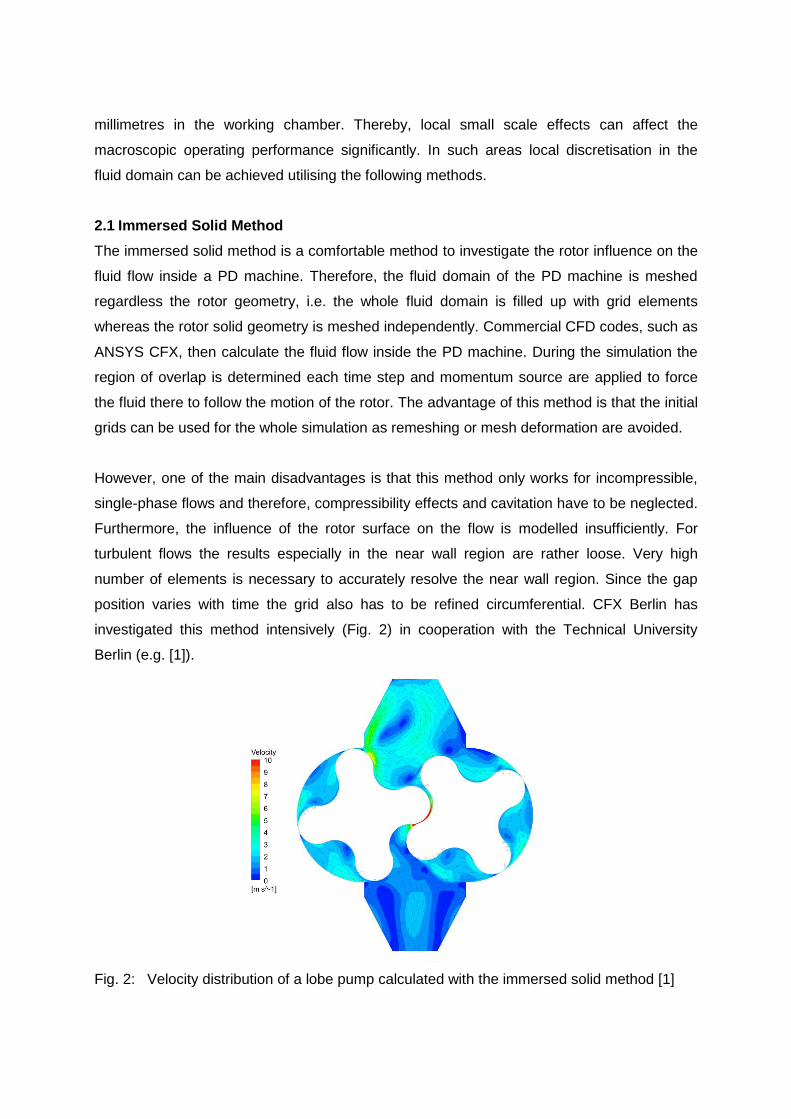
position varies with time the grid also has to be refined circumferential. CFX Berlin has
investigated this method intensively (Fig. 2) in cooperation with the Technical University
Berlin (e.g. [1]).
Fig. 2: Velocity distribution of a lobe pump calculated with the immersed solid method [1]
2.2 Remeshing
The remeshing method utilises an algorithm that generates a new mesh during run-time
depending on the rotor position and local mesh quality. At each time step the grid is
deformed due to the new rotor positions, and a routine automatically decides whether this
grid needs to be remeshed or not depending on the mesh quality. Thus, the user interaction
is small. Compared to the immersed solid method, the rotor surface is accounted for in a way
that the near wall region can be treated more accurately. Also, multi-phase flows can be
calculated.
The main disadvantage is that remeshing in small gaps is almost unavoidable for almost
every angle increment. On the one hand, the time step size needs to be small in order to
compute the mesh deformation accurately. On the other hand, every remeshing needs
interpolated results from the previous time step, which can result in interpolation errors.
Furthermore, the remeshing method must use an automatic grid generation programme.
Such programmes often use unstructured mesh elements that result in high elements
numbers within the gaps or in poor mesh quality within the gaps.
2.3 Customised Grid Generation (CGG)
In order to avoid the aforementioned disadvantages the grids have to be customised by the
engineer her/himself. Each new rotor position results in a change of the fluid domain and
therefore, every position needs to be meshed individually. One popular software tool for this
is ANSYS ICEM CFD Hexa. ANSYS ICEM CFD Hexa is capable of generating structured
grids consisting only of hexahedral elements. Additionally, an O-grid type mesh can be
utilised to mesh the rotor geometry, which is essential in accurately resolving flows in the
gaps. In order to connect each rotor grid for every rotor position interface areas between the
rotors have to be defined. The topology, i.e. node number and element links, between the
rotor positions has to remain the same or otherwise interpolation errors such as for the
remeshing method will occur. Consequently, a method or routine has to be used that only
communicates the change in node location for each rotor position to the solver. Such a
routine can be implemented into the ANSYS software rather easily. Nevertheless, the main
work needs to be done for the individual grid generation that usually consumes a lot of time.
It is imperative that the grid motion that changes from one position to the next is most even.
The angle increments should be small but have to be fixed because for every time step a grid
has to be generated. This fact reduces the option to change time step sizes during the
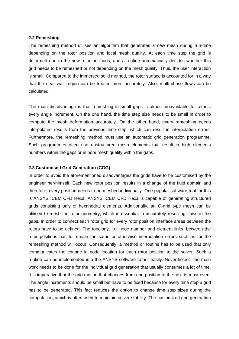
computation, which is often used to maintain solver stability. The customized grid generation
method is of high numerical quality and has been developed and utilized by CFX Berlin
Software GmbH in cooperation with industrial partners. Results (Fig. 3 and 4) from those
simulations have been validated ([2] and [3]). However, the time-consuming grid generation
rules out that this method can be used efficiently for industrial purposes. Hence, another
approach had to be investigated in that ensures high quality mesh generation at moderate
operation times and user interaction. This is realised with CFX Berlin’s TwinMesh.
Fig. 3: Velocity distribution in an internal
gear pump (CGG) [2]
Fig. 4: Velocity distribution of a 2D-
simulation of a lobe pump (CGG) [3]
3. Basics of TwinMesh
TwinMesh is a meshing software for PD machines with two axially parallel rotors, with
complex rotor geometry, i.e. continuous (e.g. lobe pump) or discontinuous (e.g. screw
compressor). Via IGES-format and alternatively point wise CSV-format, CAD-data of the
rotor and casing can be imported that represents the fluid domain and is used for the
structured grid generation.
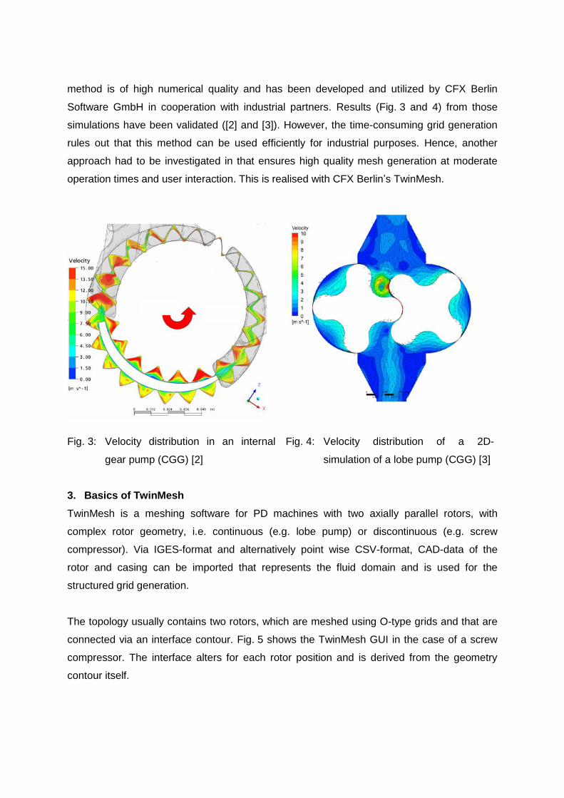
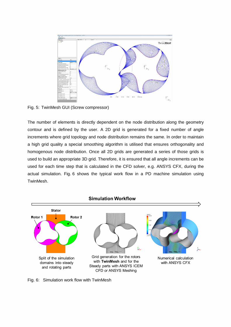
The topology usually contains two rotors, which are meshed using O-type grids and that are
connected via an interface contour. Fig. 5 shows the TwinMesh GUI in the case of a screw
compressor. The interface alters for each rotor position and is derived from the geometry
contour itself.
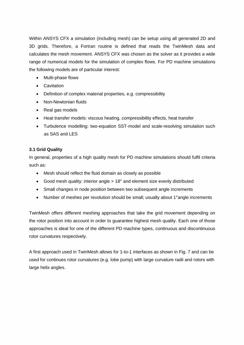
The number of elements is directly dependent on the node distribution along the geometry
contour and is defined by the user. A 2D grid is generated for a fixed number of angle
increments where grid topology and node distribution remains the same. In order to maintain
a high grid quality a special smoothing algorithm is utilised that ensures orthogonality and
homogenous node distribution. Once all 2D grids are generated a series of those grids is
used to build an appropriate 3D grid. Therefore, it is ensured that all angle increments can be
used for each time step that is calculated in the CFD solver, e.g. ANSYS CFX, during the
actual simulation. Fig. 6 shows the typical work flow in a PD machine simulation using
TwinMesh.
Fig. 5: TwinMesh GUI (Screw compressor)
Fig. 6: Simulation work flow with TwinMesh
Within ANSYS CFX a simulation (including mesh) can be setup using all generated 2D and
3D grids. Therefore, a Fortran routine is defined that reads the TwinMesh data and
calculates the mesh movement. ANSYS CFX was chosen as the solver as it provides a wide
range of numerical models for the simulation of complex flows. For PD machine simulations
the following models are of particular interest:
Multi-phase flows
Cavitation
Definition of complex material properties, e.g. compressibility
Non-Newtonian fluids
Real gas models
Heat transfer models: viscous heating, compressibility effects, heat transfer
Turbulence modelling: two-equation SST-model and scale-resolving simulation such
as SAS and LES
3.1 Grid Quality
In general, properties of a high quality mesh for PD machine simulations should fulfil criteria
such as:
Mesh should reflect the fluid domain as closely as possible
Good mesh quality: interior angle > 18° and element size evenly distributed
Small changes in node position between two subsequent angle increments
Number of meshes per revolution should be small; usually about 1°angle increments
TwinMesh offers different meshing approaches that take the grid movement depending on
the rotor position into account in order to guarantee highest mesh quality. Each one of those
approaches is ideal for one of the different PD machine types, continuous and discontinuous
rotor curvatures respectively.
A first approach used in TwinMesh allows for 1-to-1 interfaces as shown in Fig. 7 and can be
used for continues rotor curvatures (e.g. lobe pump) with large curvature radii and rotors with
large helix angles.
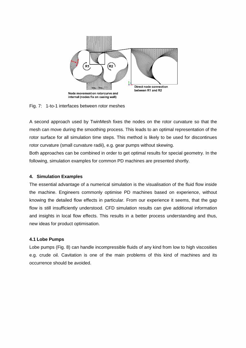
Fig. 7: 1-to-1 interfaces between rotor meshes
A second approach used by TwinMesh fixes the nodes on the rotor curvature so that the
mesh can move during the smoothing process. This leads to an optimal representation of the
rotor surface for all simulation time steps. This method is likely to be used for discontinues
rotor curvature (small curvature radii), e.g. gear pumps without skewing.
Both approaches can be combined in order to get optimal results for special geometry. In the
following, simulation examples for common PD machines are presented shortly.
4. Simulation Examples
The essential advantage of a numerical simulation is the visualisation of the fluid flow inside
the machine. Engineers commonly optimise PD machines based on experience, without
knowing the detailed flow effects in particular. From our experience it seems, that the gap
flow is still insufficiently understood. CFD simulation results can give additional information
and insights in local flow effects. This results in a better process understanding and thus,
new ideas for product optimisation.
4.1 Lobe Pumps
Lobe pumps (Fig. 8) can handle incompressible fluids of any kind from low to high viscosities
e.g. crude oil. Cavitation is one of the main problems of this kind of machines and its
occurrence should be avoided.
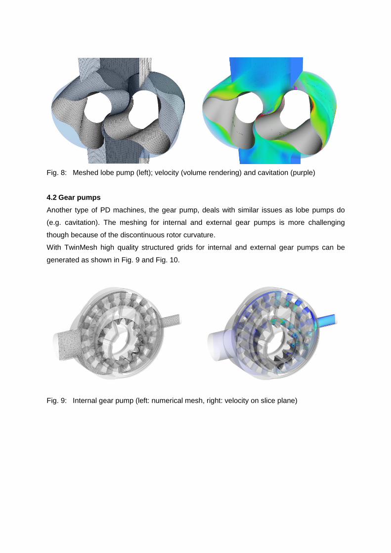
Fig. 8: Meshed lobe pump (left); velocity (volume rendering) and cavitation (purple)
4.2 Gear pumps
Another type of PD machines, the gear pump, deals with similar issues as lobe pumps do
(e.g. cavitation). The meshing for internal and external gear pumps is more challenging
though because of the discontinuous rotor curvature.
With TwinMesh high quality structured grids for internal and external gear pumps can be
generated as shown in Fig. 9 and Fig. 10.
Fig. 9: Internal gear pump (left: numerical mesh, right: velocity on slice plane)
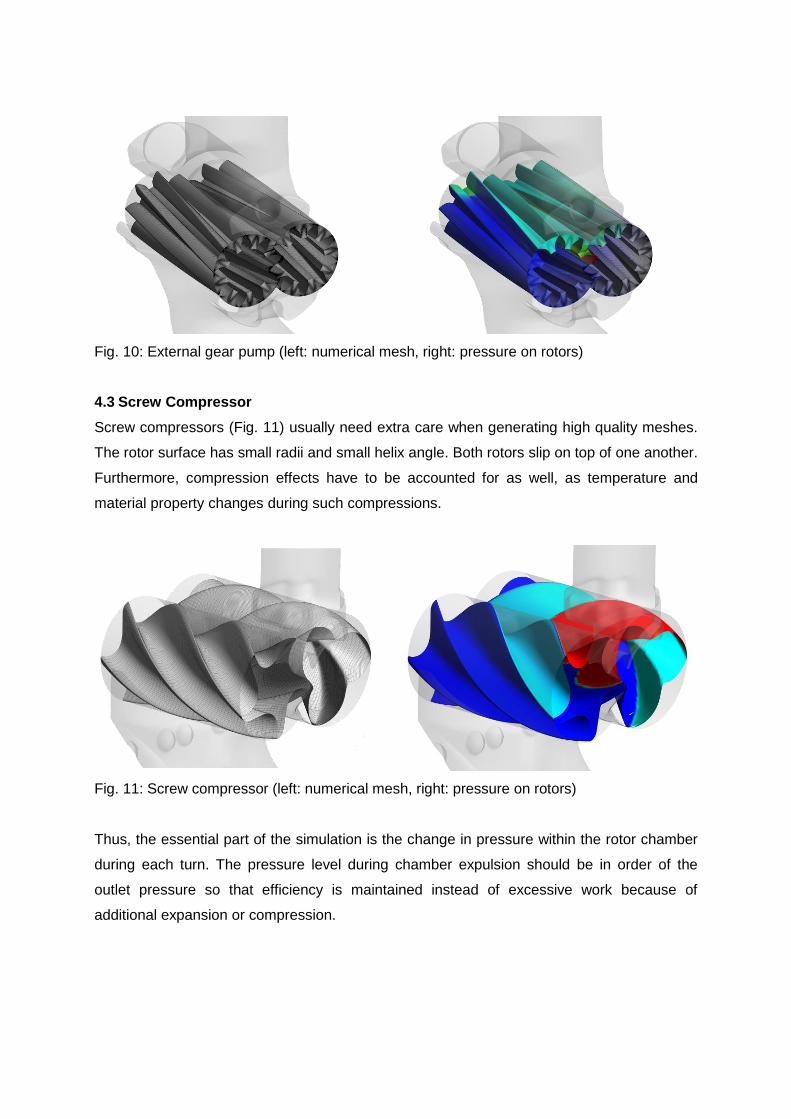
Fig. 10: External gear pump (left: numerical mesh, right: pressure on rotors)
4.3 Screw Compressor
Screw compressors (Fig. 11) usually need extra care when generating high quality meshes.
The rotor surface has small radii and small helix angle. Both rotors slip on top of one another.
Furthermore, compression effects have to be accounted for as well, as temperature and
material property changes during such compressions.
Fig. 11: Screw compressor (left: numerical mesh, right: pressure on rotors)
Thus, the essential part of the simulation is the change in pressure within the rotor chamber
during each turn. The pressure level during chamber expulsion should be in order of the
outlet pressure so that efficiency is maintained instead of excessive work because of
additional expansion or compression.
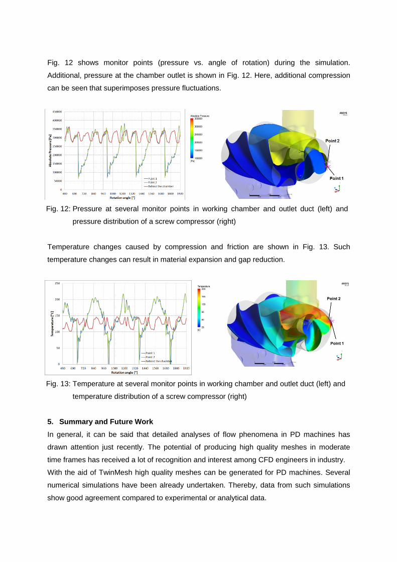
Fig. 12 shows monitor points (pressure vs. angle of rotation) during the simulation.
Additional, pressure at the chamber outlet is shown in Fig. 12. Here, additional compression
can be seen that superimposes pressure fluctuations.
Fig. 12: Pressure at several monitor points in working chamber and outlet duct (left) and
pressure distribution of a screw compressor (right)
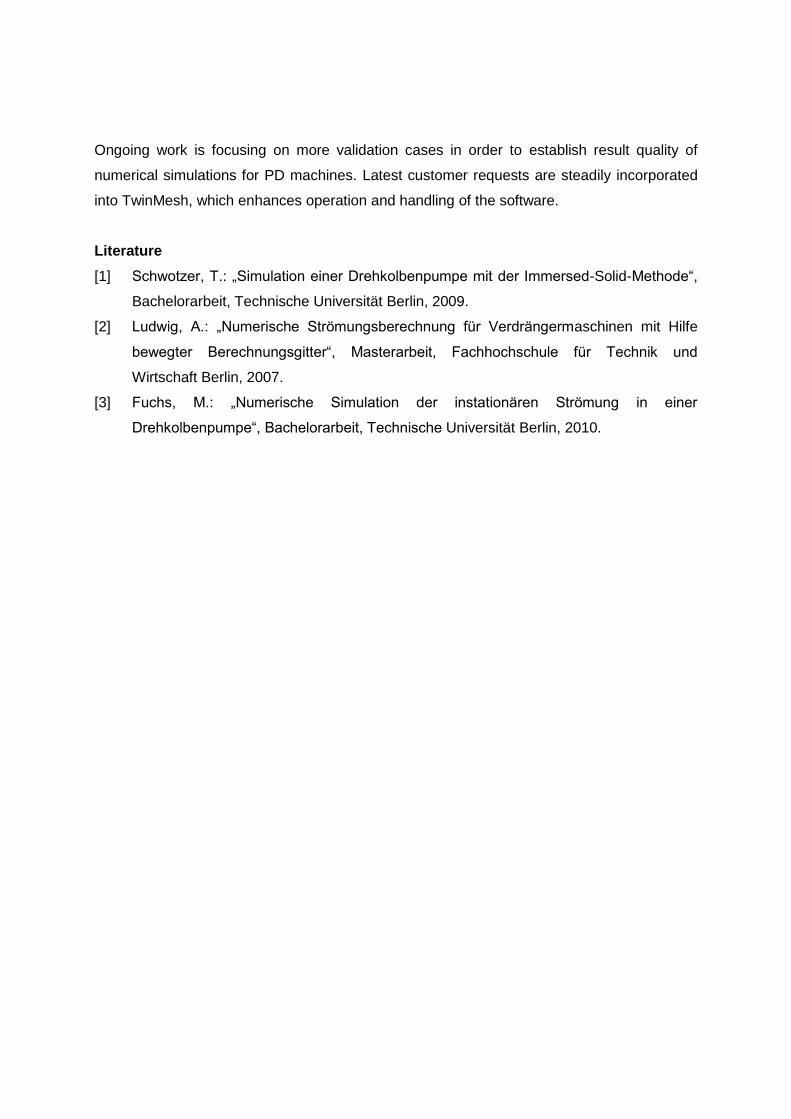
Temperature changes caused by compression and friction are shown in Fig. 13. Such
temperature changes can result in material expansion and gap reduction.
Fig. 13: Temperature at several monitor points in working chamber and outlet duct (left) and
temperature distribution of a screw compressor (right)
5. Summary and Future Work
In general, it can be said that detailed analyses of flow phenomena in PD machines has
drawn attention just recently. The potential of producing high quality meshes in moderate
time frames has received a lot of recognition and interest among CFD engineers in industry.
With the aid of TwinMesh high quality meshes can be generated for PD machines. Several
numerical simulations have been already undertaken. Thereby, data from such simulations
show good agreement compared to experimental or analytical data.
Ongoing work is focusing on more validation cases in order to establish result quality of
numerical simulations for PD machines. Latest customer requests are steadily incorporated
into TwinMesh, which enhances operation and handling of the software.
Literature
[1] Schwotzer, T.: „Simulation einer Drehkolbenpumpe mit der Immersed-Solid-Methode“,
Bachelorarbeit, Technische Universität Berlin, 2009.
[2] Ludwig, A.: „Numerische Strömungsberechnung für Verdrängermaschinen mit Hilfe
bewegter Berechnungsgitter“, Masterarbeit, Fachhochschule für Technik und
Wirtschaft Berlin, 2007.
[3] Fuchs, M.: „Numerische Simulation der instationären Strömung in einer
Drehkolbenpumpe“, Bachelorarbeit, Technische Universität Berlin, 2010.