Embed Size (px)
Citation preview

19 May 2011 1 of 30
ELIXIR Course
Structural Design
Jean-Christophe Salvignol SRE/PJ(JWST NIRSpec & MIRI Mechanical Eng.)
19 May 2011 2 of 30
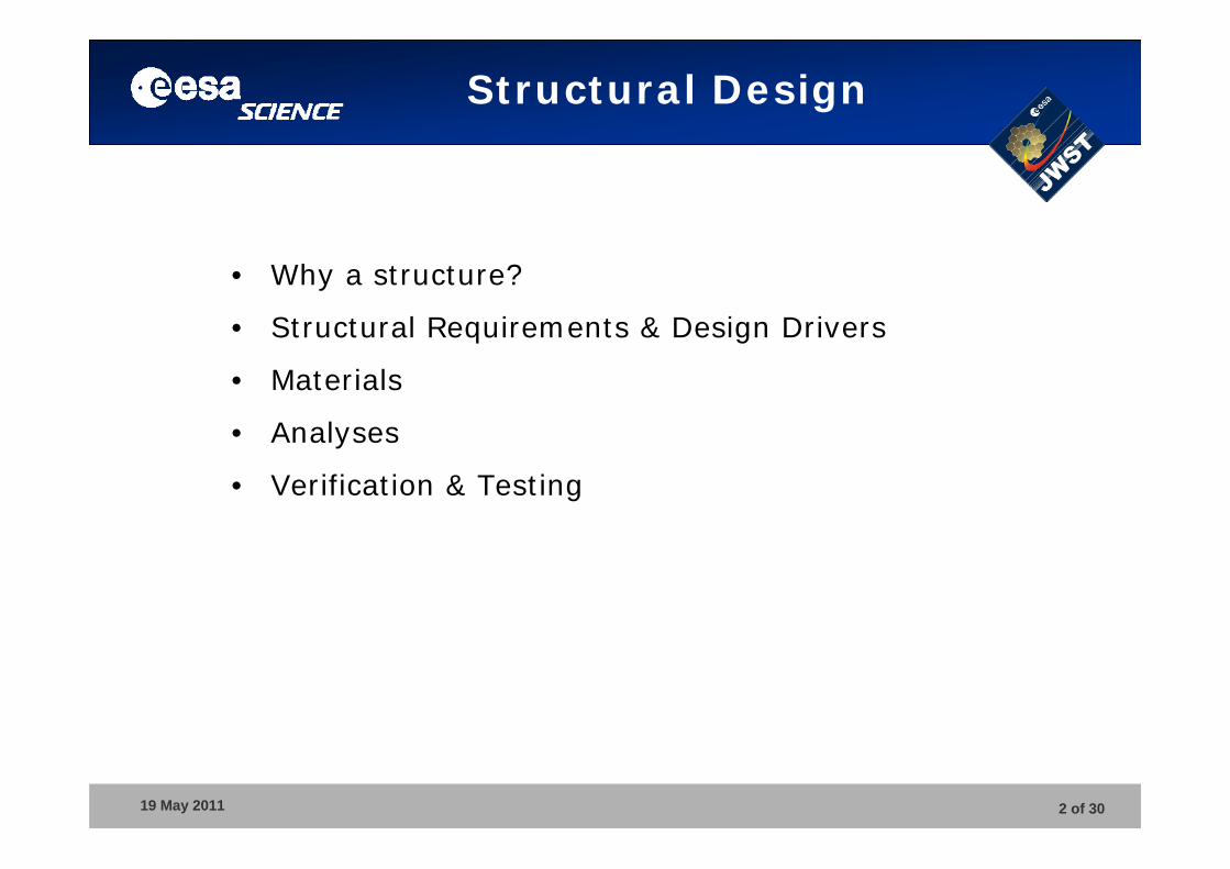
Structural Design
• Why a structure?
• Structural Requirements & Design Drivers
• Materials
• Analyses
• Verification & Testing
19 May 2011 3 of 30
Structural Design
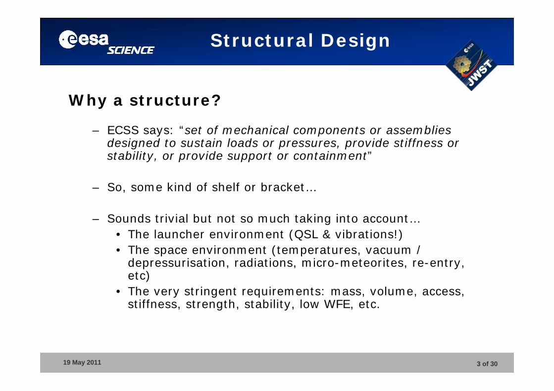
Why a structure?
– ECSS says: “set of mechanical components or assemblies designed to sustain loads or pressures, provide stiffness or stability, or provide support or containment”
– So, some kind of shelf or bracket…
– Sounds trivial but not so much taking into account…• The launcher environment (QSL & vibrations!) • The space environment (temperatures, vacuum /
depressurisation, radiations, micro-meteorites, re-entry, etc)
• The very stringent requirements: mass, volume, access, stiffness, strength, stability, low WFE, etc.
19 May 2011 4 of 30
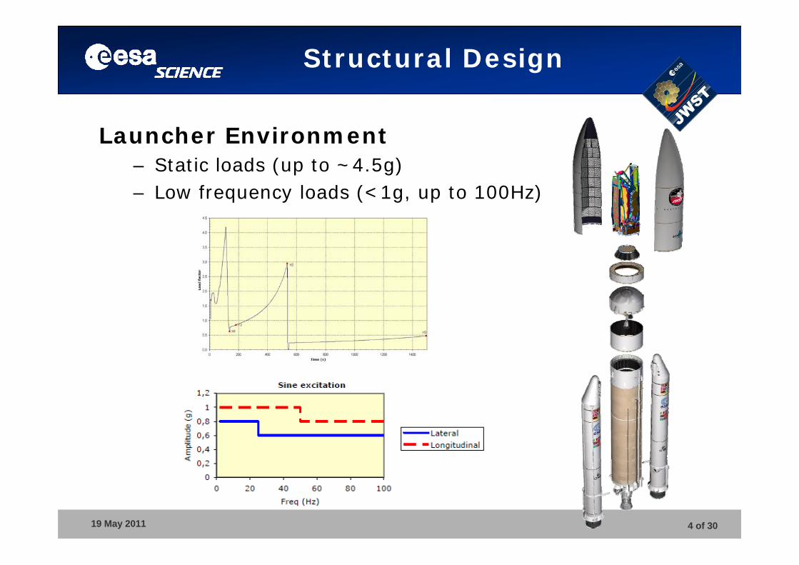
Structural Design
Launcher Environment– Static loads (up to ~4.5g)– Low frequency loads (<1g, up to 100Hz)
19 May 2011 5 of 30
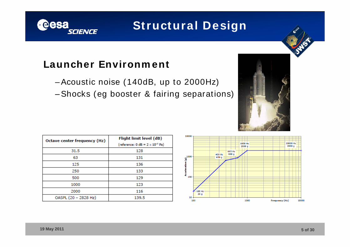
Structural Design
Launcher Environment
–Acoustic noise (140dB, up to 2000Hz)–Shocks (eg booster & fairing separations)
19 May 2011 6 of 30
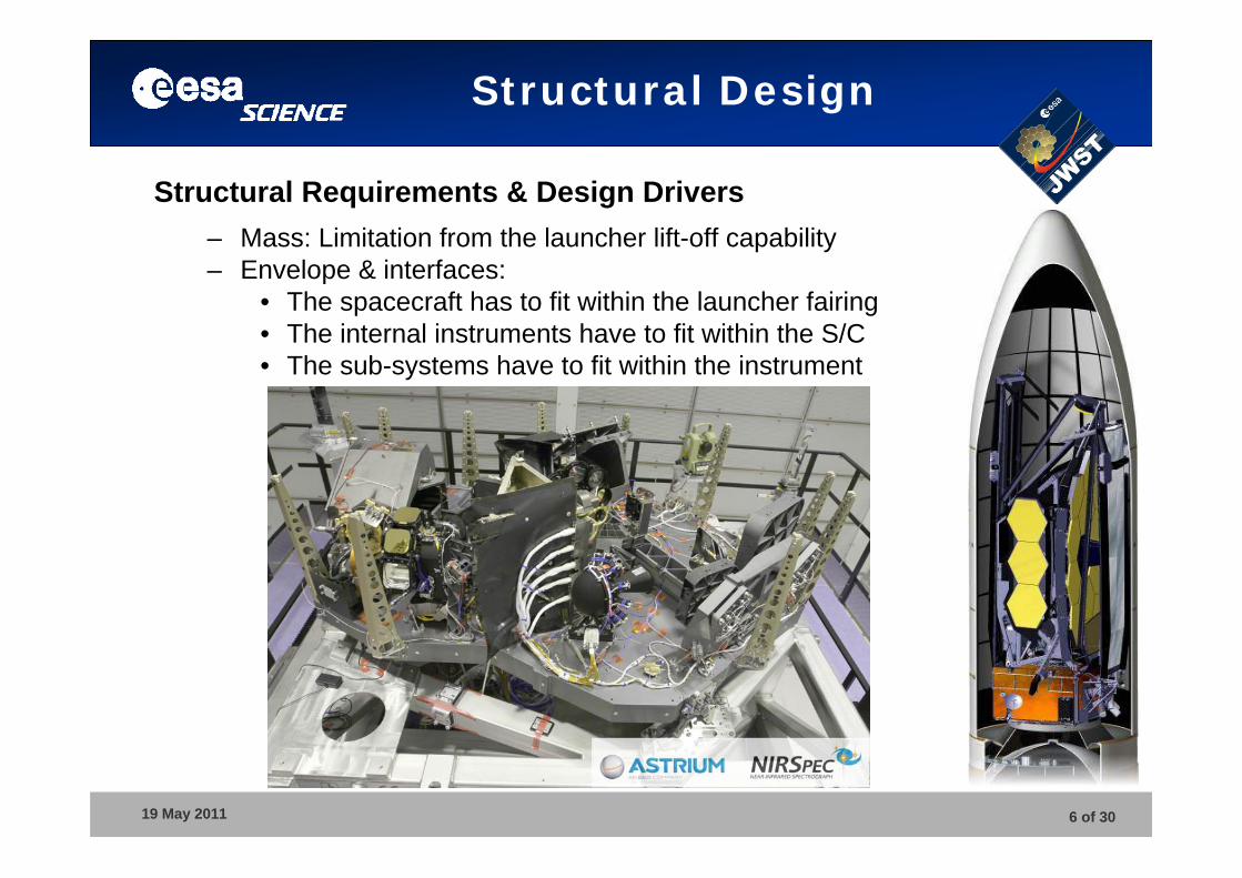
Structural Design
Structural Requirements & Design Drivers– Mass: Limitation from the launcher lift-off capability– Envelope & interfaces:
• The spacecraft has to fit within the launcher fairing• The internal instruments have to fit within the S/C• The sub-systems have to fit within the instrument
19 May 2011 7 of 30
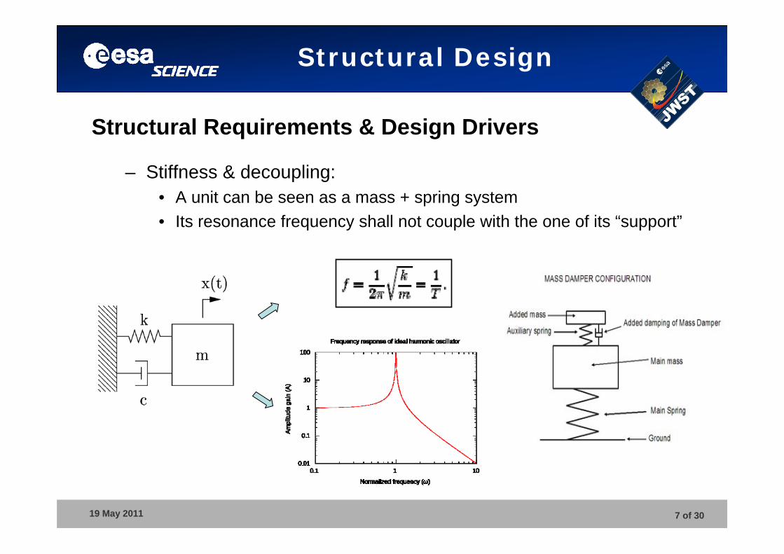
Structural Design
Structural Requirements & Design Drivers
– Stiffness & decoupling:• A unit can be seen as a mass + spring system• Its resonance frequency shall not couple with the one of its “support”
19 May 2011 8 of 30
Structural Design
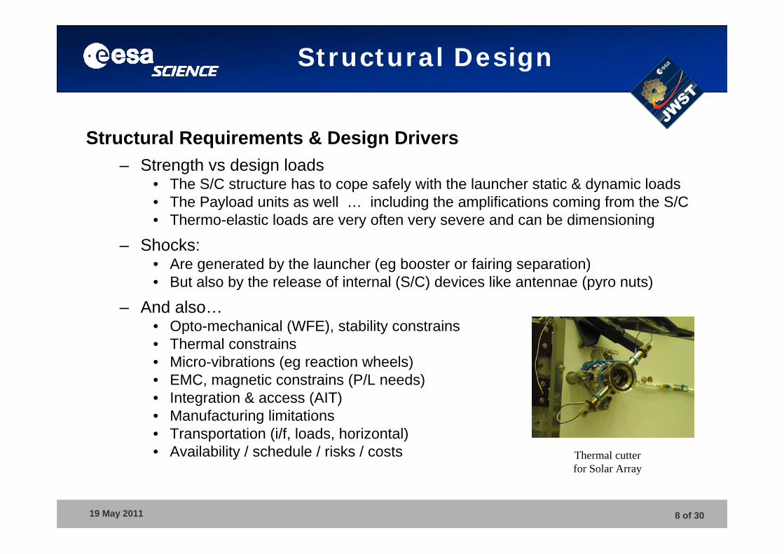
Structural Requirements & Design Drivers– Strength vs design loads
• The S/C structure has to cope safely with the launcher static & dynamic loads• The Payload units as well … including the amplifications coming from the S/C• Thermo-elastic loads are very often very severe and can be dimensioning
– Shocks: • Are generated by the launcher (eg booster or fairing separation)• But also by the release of internal (S/C) devices like antennae (pyro nuts)
– And also…• Opto-mechanical (WFE), stability constrains• Thermal constrains• Micro-vibrations (eg reaction wheels)• EMC, magnetic constrains (P/L needs)• Integration & access (AIT)• Manufacturing limitations• Transportation (i/f, loads, horizontal)• Availability / schedule / risks / costs Thermal cutter
for Solar Array
19 May 2011 9 of 30
Structural Design
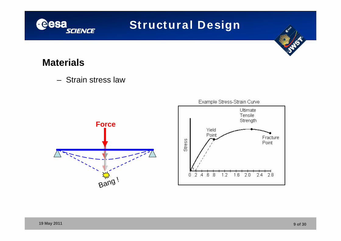
Materials– Strain stress law
Force
Bang !
19 May 2011 10 of 30
Structural Design
Materials
– Metals: recommended as far as possible, and aluminium if possible!
– Lots of experience, well characterised– Easy to machine … and in many places– Low safety factors (less conservative dimensioning)– Can be repaired, modified at a late stage, etc– Cheap and easily available
19 May 2011 11 of 30
Structural Design
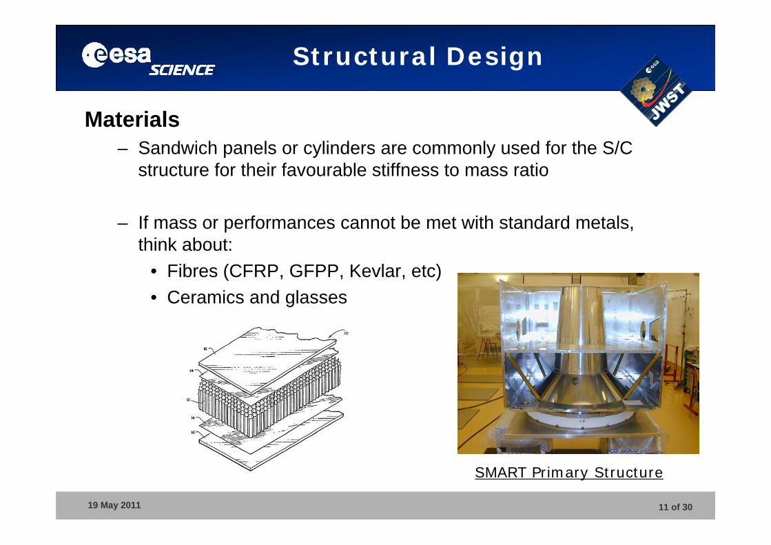
Materials– Sandwich panels or cylinders are commonly used for the S/C
structure for their favourable stiffness to mass ratio
– If mass or performances cannot be met with standard metals, think about:
• Fibres (CFRP, GFPP, Kevlar, etc)• Ceramics and glasses
SMART Primary Structure
19 May 2011 12 of 30
Structural Design
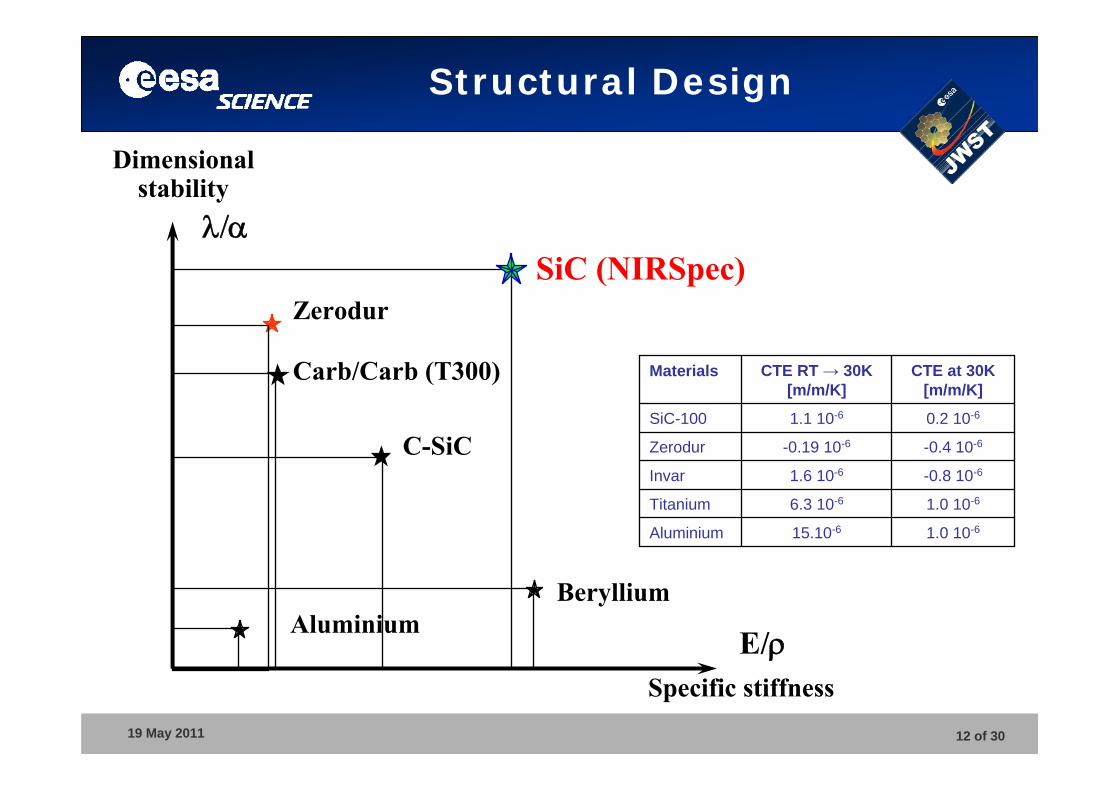
Dimensional stability
Specific stiffness
SiC (NIRSpec)Zerodur
AluminiumBeryllium
E/
Carb/Carb (T300)
C-SiC
1.0 10-615.10-6Aluminium
1.0 10-66.3 10-6Titanium
-0.8 10-61.6 10-6Invar
-0.4 10-6-0.19 10-6Zerodur
0.2 10-61.1 10-6SiC-100
CTE at 30K[m/m/K]
CTE RT → 30K[m/m/K]
Materials
19 May 2011 13 of 30
Structural Design
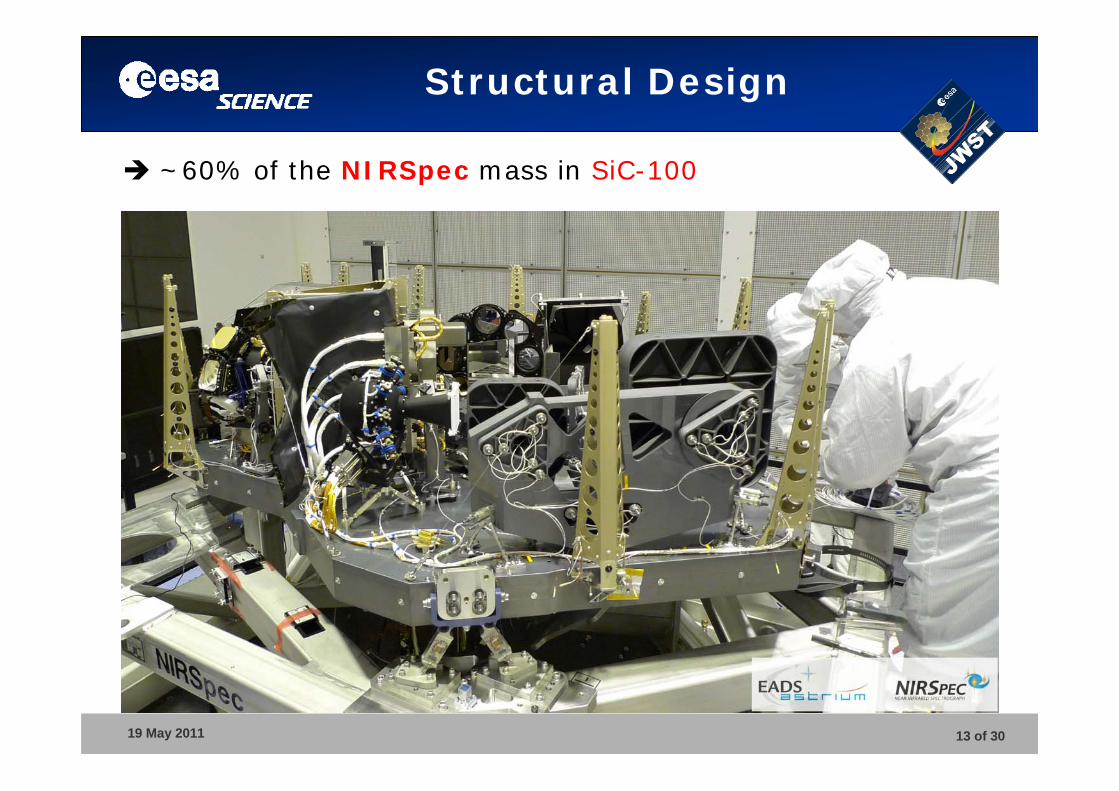
~60% of the NIRSpec mass in SiC-100
19 May 2011 14 of 30
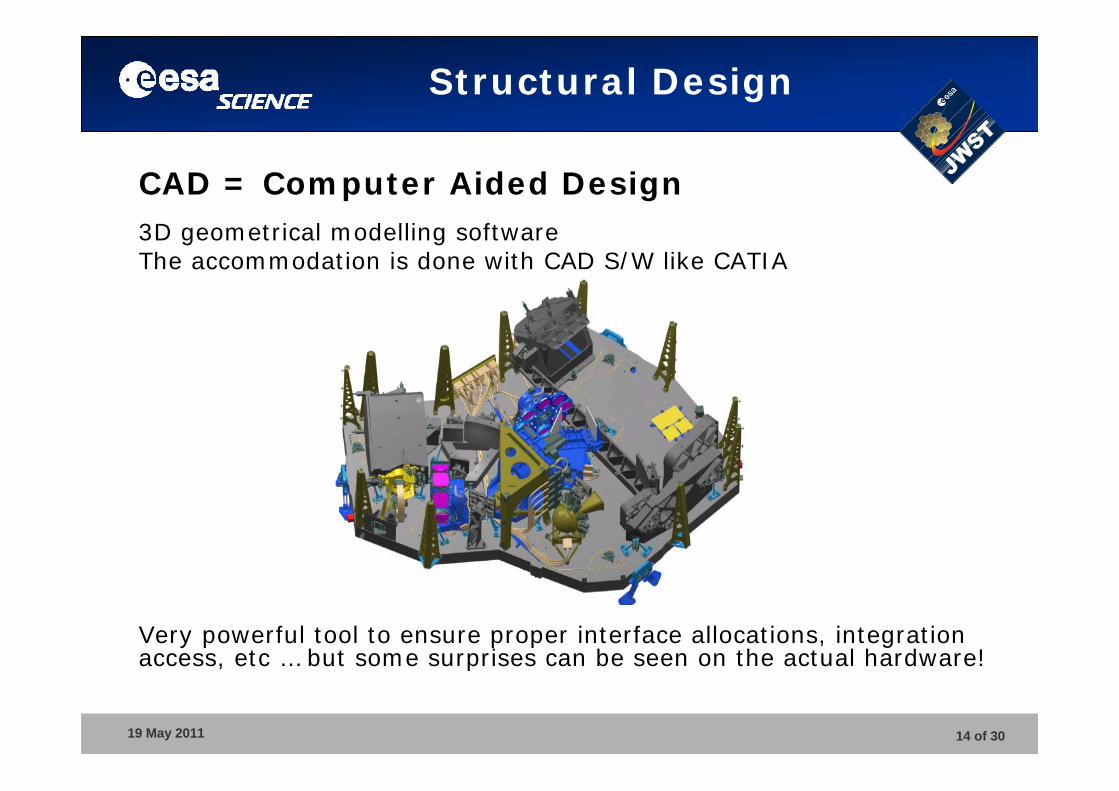
CAD = Computer Aided Design3D geometrical modelling softwareThe accommodation is done with CAD S/W like CATIA
Very powerful tool to ensure proper interface allocations, integration access, etc … but some surprises can be seen on the actual hardware!
Structural Design
19 May 2011 15 of 30
Structural Design
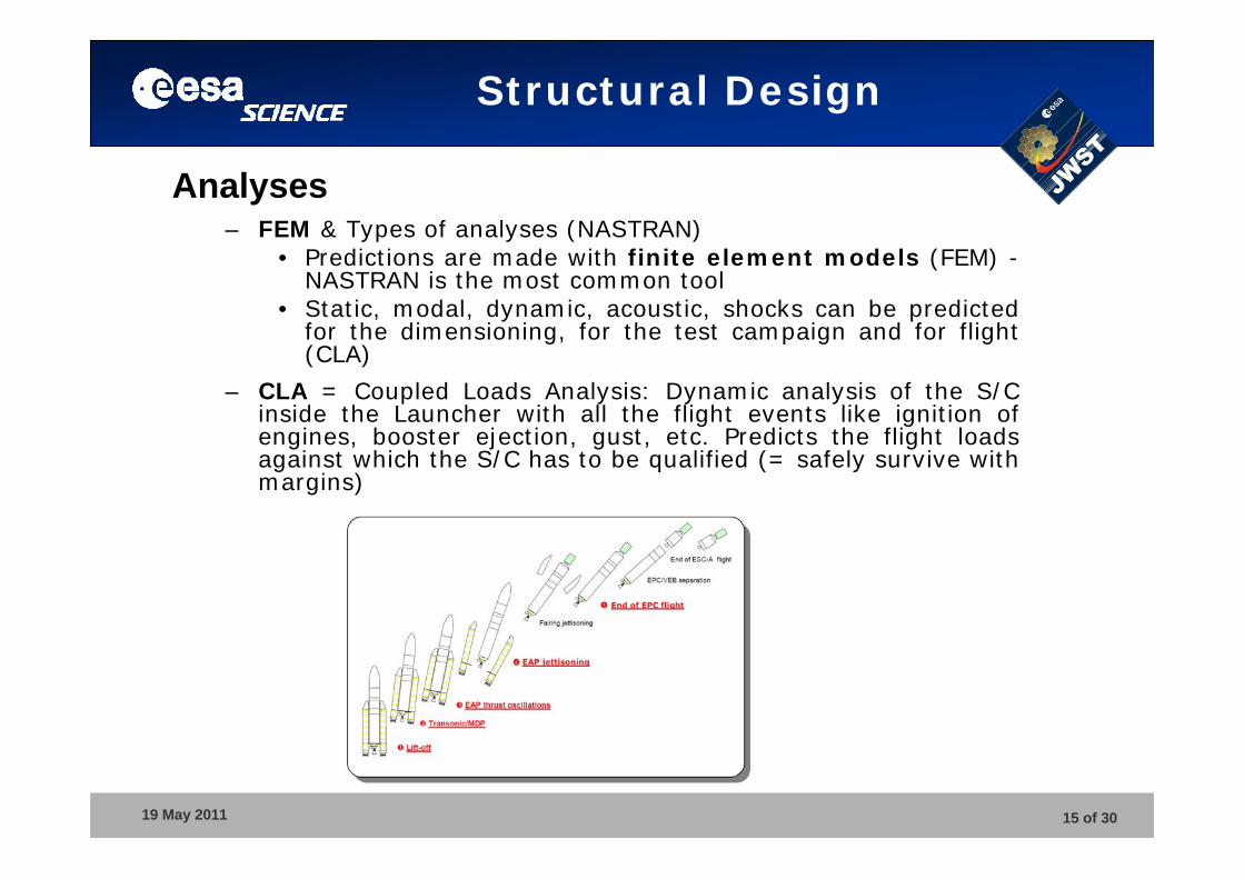
Analyses– FEM & Types of analyses (NASTRAN)
• Predictions are made with finite element models (FEM) -NASTRAN is the most common tool
• Static, modal, dynamic, acoustic, shocks can be predicted for the dimensioning, for the test campaign and for flight (CLA)
– CLA = Coupled Loads Analysis: Dynamic analysis of the S/C inside the Launcher with all the flight events like ignition of engines, booster ejection, gust, etc. Predicts the flight loads against which the S/C has to be qualified (= safely survive withmargins)
19 May 2011 16 of 30
Structural Design
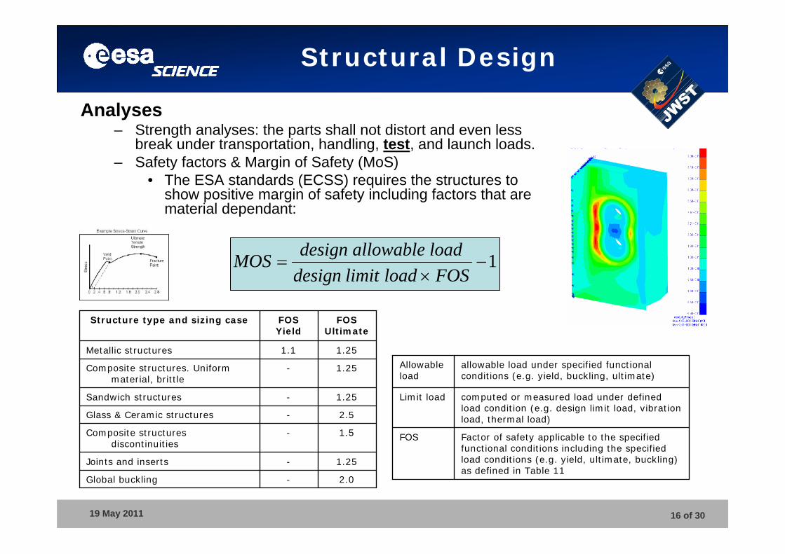
2.0-Global buckling
1.25-Joints and inserts
1.5-Composite structures discontinuities
2.5-Glass & Ceramic structures
1.25-Sandwich structures
1.25-Composite structures. Uniform material, brittle
1.251.1Metallic structures
FOSUltimate
FOSYield
Structure type and sizing case
Analyses– Strength analyses: the parts shall not distort and even less
break under transportation, handling, test, and launch loads.– Safety factors & Margin of Safety (MoS)
• The ESA standards (ECSS) requires the structures to show positive margin of safety including factors that are material dependant:
1
FOSloadlimitdesign
loadallowabledesignMOS
Factor of safety applicable to the specified functional conditions including the specified load conditions (e.g. yield, ultimate, buckling) as defined in Table 11
FOS
computed or measured load under defined load condition (e.g. design limit load, vibration load, thermal load)
Limit load
allowable load under specified functional conditions (e.g. yield, buckling, ultimate)
Allowable load
19 May 2011 17 of 30
Structural Design
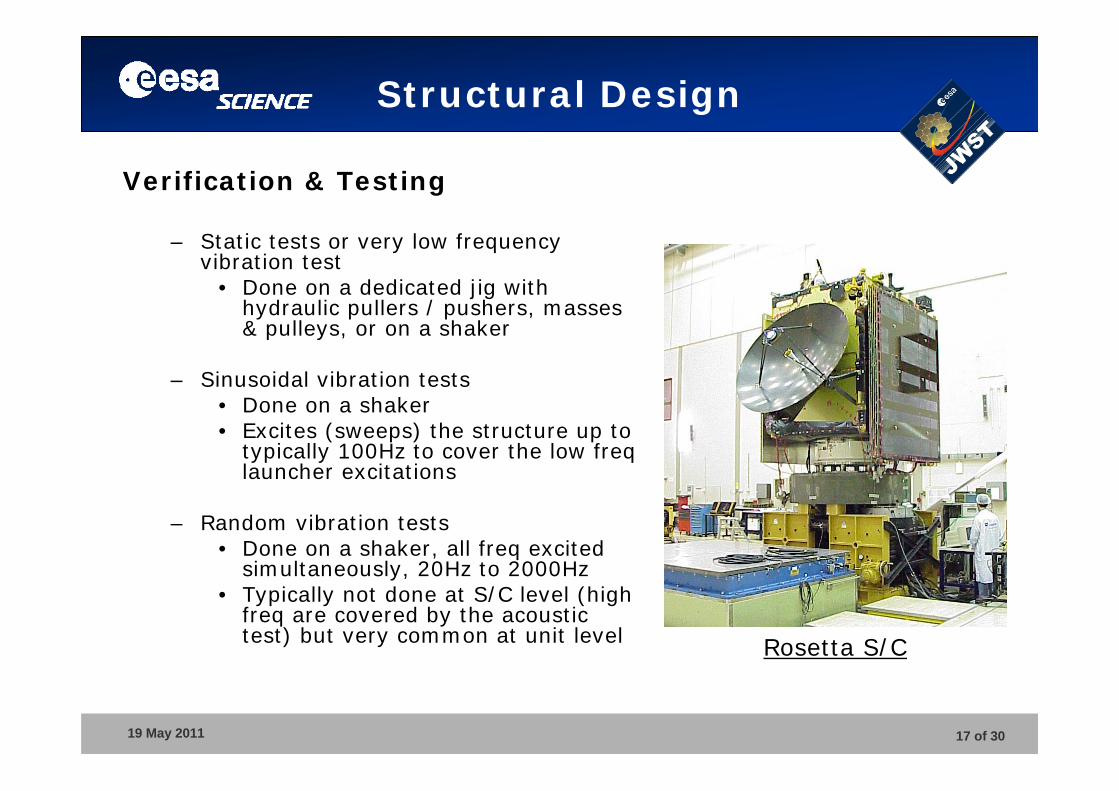
Verification & Testing
– Static tests or very low frequency vibration test
• Done on a dedicated jig with hydraulic pullers / pushers, masses & pulleys, or on a shaker
– Sinusoidal vibration tests• Done on a shaker• Excites (sweeps) the structure up to
typically 100Hz to cover the low freq launcher excitations
– Random vibration tests• Done on a shaker, all freq excited
simultaneously, 20Hz to 2000Hz• Typically not done at S/C level (high
freq are covered by the acoustic test) but very common at unit level Rosetta S/C
19 May 2011 18 of 30
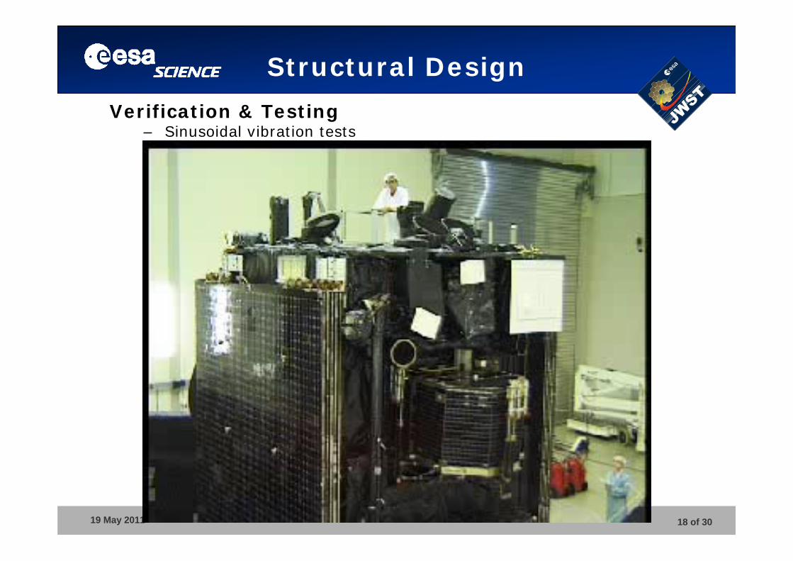
Structural Design
Verification & Testing– Sinusoidal vibration tests
19 May 2011 19 of 30
Structural Design
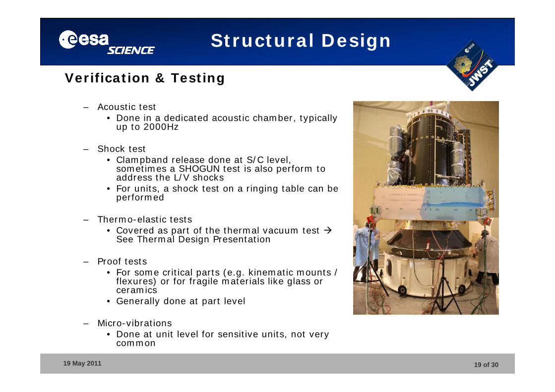
Verification & Testing
– Acoustic test• Done in a dedicated acoustic chamber, typically
up to 2000Hz
– Shock test• Clampband release done at S/C level,
sometimes a SHOGUN test is also perform to address the L/V shocks
• For units, a shock test on a ringing table can be performed
– Thermo-elastic tests• Covered as part of the thermal vacuum test
See Thermal Design Presentation
– Proof tests• For some critical parts (e.g. kinematic mounts /
flexures) or for fragile materials like glass or ceramics
• Generally done at part level
– Micro-vibrations• Done at unit level for sensitive units, not very
common
19 May 2011 20 of 30
Structural Design
Now, you cannot probably make a S/C or Payload structure yet…
… but you should be able to talk with better confidence to a structural engineer!
19 May 2011 21 of 30
ELIXIR Course
Mechanisms
Jean-Christophe Salvignol SRE/PJ(JWST NIRSpec & MIRI Mechanical Eng.)
19 May 2011 22 of 30
Mechanisms
• Rule number 1• Why using mechanisms?• Design drivers• Analyses• Verification and Testing
19 May 2011 23 of 30
Mechanisms
Design Rule No 1:
Do not use mechanisms(as far as you can…)
It’s a source of problems, delays, costs…Forget about flight heritage in 99% of the cases!
19 May 2011 24 of 30
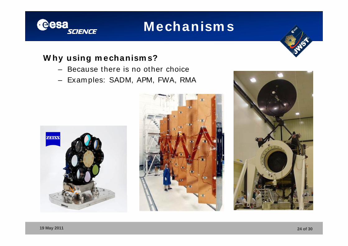
Mechanisms
Why using mechanisms?– Because there is no other choice– Examples: SADM, APM, FWA, RMA
19 May 2011 25 of 30
Mechanisms
19 May 2011 26 of 30
Mechanisms
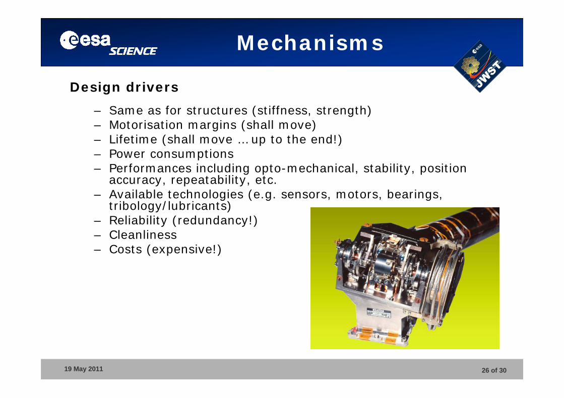
Design drivers
– Same as for structures (stiffness, strength)– Motorisation margins (shall move)– Lifetime (shall move … up to the end!)– Power consumptions– Performances including opto-mechanical, stability, position
accuracy, repeatability, etc.– Available technologies (e.g. sensors, motors, bearings,
tribology/lubricants)– Reliability (redundancy!)– Cleanliness– Costs (expensive!)
19 May 2011 27 of 30
Mechanisms
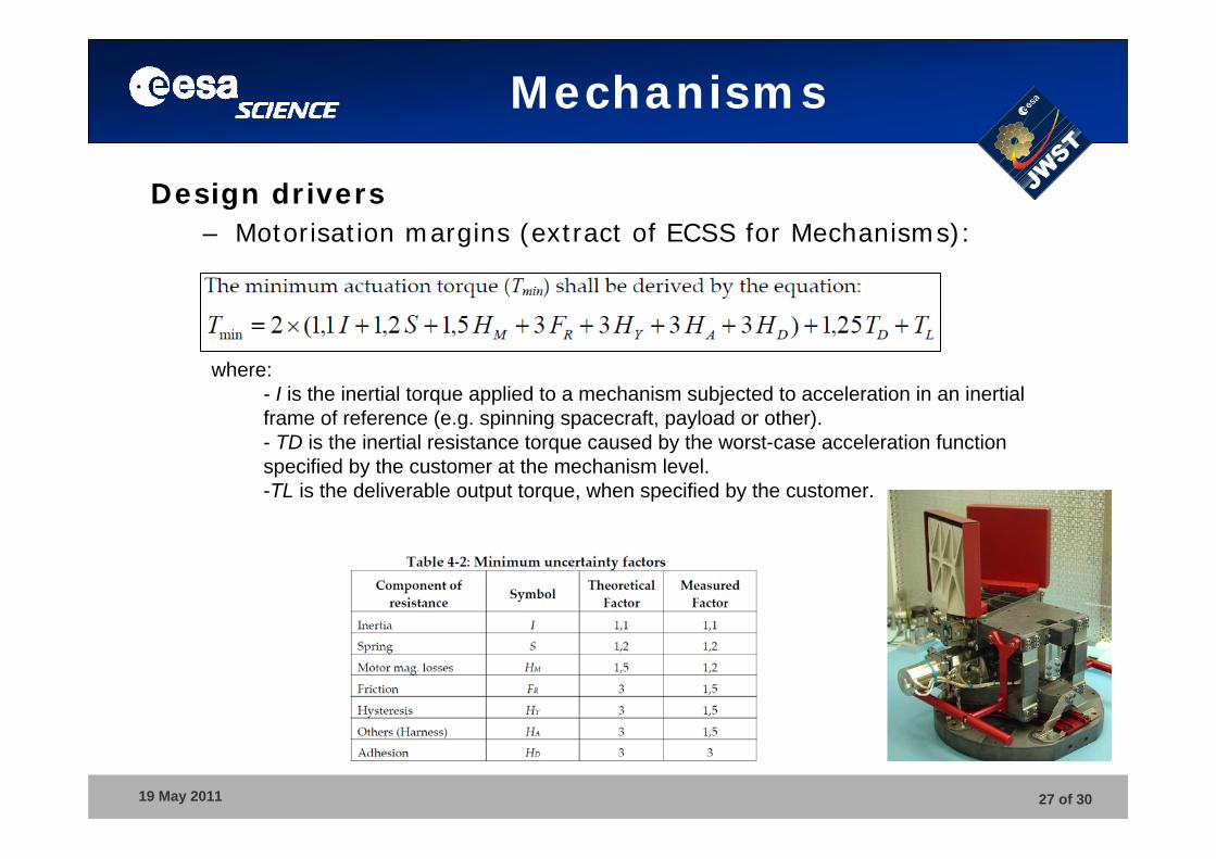
Design drivers– Motorisation margins (extract of ECSS for Mechanisms):
where: - I is the inertial torque applied to a mechanism subjected to acceleration in an inertial frame of reference (e.g. spinning spacecraft, payload or other).- TD is the inertial resistance torque caused by the worst-case acceleration function specified by the customer at the mechanism level. -TL is the deliverable output torque, when specified by the customer.
19 May 2011 28 of 30
Mechanisms
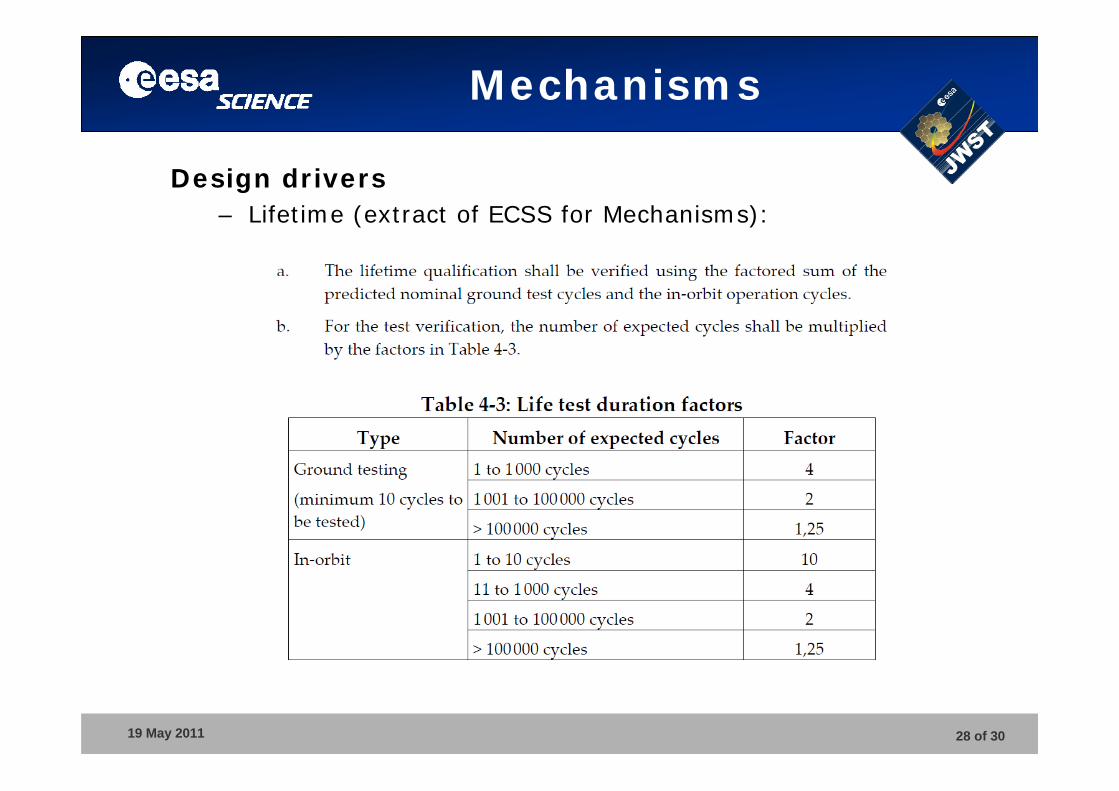
Design drivers– Lifetime (extract of ECSS for Mechanisms):
19 May 2011 29 of 30
Mechanisms
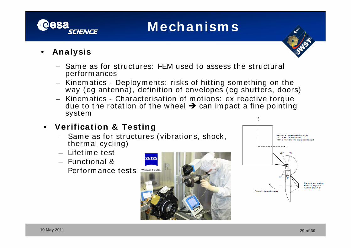
• Analysis
– Same as for structures: FEM used to assess the structural performances
– Kinematics - Deployments: risks of hitting something on the way (eg antenna), definition of envelopes (eg shutters, doors)
– Kinematics - Characterisation of motions: ex reactive torque due to the rotation of the wheel can impact a fine pointing system
• Verification & Testing– Same as for structures (vibrations, shock,
thermal cycling)– Lifetime test– Functional &
Performance tests
19 May 2011 30 of 30
Mechanisms
Reminder of Design Rule No 1:
Do not use mechanisms!(as far as you can…)
QUESTIONS?