Embed Size (px)
Citation preview

16031000F
WELDING BUSINESS
http://www.kobelco.co.jp/english/welding/International Sales & Marketing Section 9-12, Kita-Shinagawa 5-chome, Shinagawa-ku, TOKYO 141-8688, JAPAN +81-3-5739-6332 (Tel) +81-3-5739-6960 (Fax)
The products and services represented in this catalog are governed by the export restrictions of the Japanese Foreign Exchange and Foreign Trade Act. A Japanese government issued export permit may be necessary to export outside Japan.If export is intended, kindly consult Kobe Steel, Ltd. Welding Business and/or its sales offices. Please be advised in advance that we reserve the right to confirm the export destination includ-ing the nature and/or intended use of our products and services at the said destination.
STRUCTURAL STEEL WELDING ROBOT SYSTEM
WELDING ROBOTSTRUCTURAL STEEL
WELDING ROBOT SYSTEM
WELDING ROBOT

21
Welding robot systems for structural steel from Japan’s leading welding company “ ”Kobe Steel, the only welding solutions company that develops all of its own original welding robots, welding power supplies and welding wires aims to be your No.1 partner for structural steel fabrication.
● We provide robot systems that contribute to the quality and control of the production process● We also support new processes and new standards
Through our in-depth understanding of the welding process, our aim is to make a system that fabricators can trust and use with confidence
page
3
5
7
9
11
12
13
14
15
17
19
20
21
21
Compact Structural Steel Connection
Structural Steel Connection ”2-ARC”
Structural Steel Connection
Multi-work Structural Steel Connection
Structural Beam
Full-package Structural Steel Connection
System configuration and specifications
Peripheral equipment
Input screen
Application
Structural Steel Large Assembly “2-ARC”
Features of
Structural Steel Large Assembly
KOBELCO Global Service Network
ASSURING
● We aim for the best welding quality that meet certification standards and type approval for architectural structural steel● We provide support for a wide range of structural steel welding technologies and production processes
We continually pursue the optimization of structural steel weldingTRUSTWORTHY
● By raising the percentage of welding automation, we aim to increase the number of weld that can be robot-welded● Our robot is adaptable to numerous applications thus increasing the rate of return on its investment
Contributing to cost reduction through fast and high efficiency welding
EFFICIENT
● Our aim is to supply a robot system that requires minimum pre-operation setting up● Minimal data input and simple operation lessen the work load of the operator
Our welding robot system is user friendly such that anyone canoperate it from day one of its installation
EASY
STRUCTURAL STEEL WELDING ROBOT SYSTEM
WELDING ROBOT

The advantages of welding and constant voltage welding combined to give high quality welding.
3 4
Conventional
Conventional
257S : Wire section 257R : Corner section
■The technology behind
Optimal plate thickness
■Systems installed
■Scope of application
Structural Steel Welding Robot Sy stems
What is ?
Wire for
System characteristics
● Spatter on nozzle ー Spatter comparison test
● Structural Steel Large Assembly “2-ARC” Welding Robot System
● Specialized welding equipment ● Specialized welding material ● Chip changer
● Structural Steel Large Assembly Welding Robot System
● 2-ARC welding robot system for steel core connection
● Cross section of weld bead and weld penetration
System
Robot base
Wire weight
Other
Compact Structural Steel ConnectionWelding Robot System
Single welding only
MAX 650 kg / 1433lbMAX 1000 kg / 2205lb
Chip changer not included
Multi-work Structural SteelConnection Welding Robot System
Single welding only
MAX 3000 kg / 6614lb
Structural Steel ConnectionWelding Robot System
Single/ 2-ARC
MAX 2000 kg / 4409lbMAX 3000 kg / 6614lbMAX 4000 kg / 8818lb
Structural Steel Large AssemblyWelding Robot System
Single/ 2-ARC
MAX 10000 kg / 22046lbMAX 15000 kg / 33069lbMAX 20000 kg / 44092lbMAX 30000 kg / 66139lb
Chip changer included
An idea of what droplet transfer is
Typical CO2 welding
AB500
Conventional
Comparison of fume amount(%)
Amount of fumes according towire weight for bead-on-plate( )
Comparison between generated fumes
100
80
60
40
20
0
21
MG-50R(N)MG-56R(N)
MG-50R(N)MG-56R(N)
Set current(A)
mode
Constant voltagemode
Wire feeding volume(mm/min.)
High wire melting speed
About 10% increase in wire feed rate at the same currentAbout 25A decrease in current at the same wire feed rate
20000
15000
10000
5000200 250 300 350
*The conventional constant voltage mode can be used for applications other than the above
Types of Welding Robot Systems
● Optimized to reduce slag volume and slag removal for carbon dioxide multi-pass welding.
● Superior conductivity, adherence resistivity and wire feedability made possible through 's unique waveform control.
● Compatible with conventional constant voltage welding.490MPa level (YGW11): MG-50R(N)550MPa level (YGW18): MG-56R(N)
● State of spatter adhesion and fume generation after welding ー MG-56R(N)
application
application
■ Reduces production timeLow spatter means less frequent cleaning and because of reduction in spatter adhering to the work, the robot operation time and post-treatment time can be significantly reduced.Combined with the reduction in air cut time as a result of the new software, robot operation time reduction up to 20% can be expected for a column plate thickness of 22mm/0.87in, 400mm/15.75in diameter (compared to our competitors). *Time reductions may vary due to plate thickness or diameter.In addition, an automated contact chip changer is supplied as standard so chip changes are carried out automatically during operation resulting in increased continuous operability.*Space saving type welding robot systems do not come standard with a chip changer.
■ High quality weldingSince the average current can be reduced as a result of the faster wire melting rate in the welding process, the maximum heat input can be minimized.In addition, by switching between welding and constant voltage welding for each weld pass or during welding, each part can be welded appropriately.
■ Environment friendly and energy saving weldingEven whilst the wire melting rate is being increased, with our proprietary process, the average current can be lowered thereby reducing the energy consumption compared to conventional constant voltage welding (a 5% reduction in power consumption can be achieved for the same wire feed rate).Furthermore, by reducing the over-heat time for melting, the amount of fumes generated can be reduced.
1
2
3
◎HSS-Column welding Plate thickness 9~40mm / 0.35~1.57in
◎Round pipe welding Plate thickness 9~40mm / 0.35~1.57in
The process featuring our new power supply AB500 achieves systematic and smooth droplet transfer for global transfer through our original current/voltage wave form controller (patented)
● Reference layout plan
20332mm / 66.7ft:Safety fence
16800mm / 55.1ft:Occupied space
7250mm / 23.8ft:Safety fence
5300mm / 17.4ft
:Occupied space
5 6
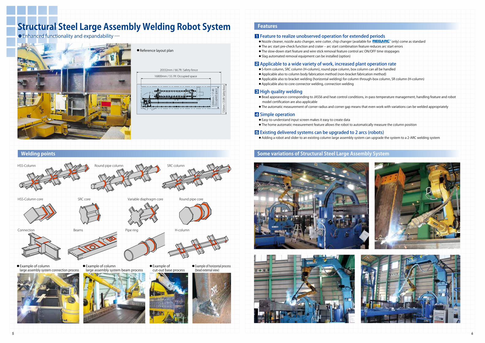
● Example of column large assembly system connection process
● Example of column large assembly system beam process
● Example of cut-out base process
● Example of horizontal process (bead external view)
Structural Steel Large Assembly Welding Robot System● Enhanced functionality and expandability-
Features
HSS-Column
HSS-Column core SRC core Variable diaphragm core Round pipe core
Round pipe column SRC column
Connection Pipe ring H-columnBeams
Welding points Some variations of Structural Steel Large Assembly System
■ Feature to realize unobserved operation for extended periods● Nozzle cleaner, nozzle auto changer, wire cutter, chip changer (available for only) come as standard● The arc start pre-check function and crater ‒ arc start combination feature reduces arc start errors● The slow-down start feature and wire stick removal feature control arc ON/OFF time stoppages● Slag automated removal equipment can be installed (option)
■ Applicable to a wide variety of work, increased plant operation rate● S-form column, SRC column (H-column), round pipe column, box column can all be handled● Applicable also to column body fabrication method (non-bracket fabrication method)● Applicable also to bracket welding (horizontal welding) for column through-box column, SR column (H-column)● Applicable also to core connector welding, connection welding
■ High quality welding● Bead appearance corresponding to JASS6 and heat control conditions, in-pass temperature management, handling feature and robot model certification are also applicable ● The automatic measurement of corner radius and corner gap means that even work with variations can be welded appropriately
■ Simple operation● Easy-to-understand input screen makes it easy to create data● The home automatic measurement feature allows the robot to automatically measure the column position
■ Existing delivered systems can be upgraded to 2 arcs (robots)● Adding a robot and slider to an existing column large assembly system can upgrade the system to a 2-ARC welding system
1
2
3
4
5
19182mm / 62.9ft:Safety fence
17000mm / 55.8ft:Occupied space
7250mm / 23.8ft:Safety fence
5300mm / 17.4ft
:Occupied space
8:00 9:00 10:00 11:00 12:00 13:00 14:00 15:00 16:00 17:00 18:00 19:00 20:00 21:00 22:00(hrs)
First column Second column
8:00 9:00 10:00 11:00 12:00 13:00 14:00 15:00 16:00 17:00 18:00 19:00 20:00 21:00 22:00
First column Second column Third column
8:00 9:00 10:00 11:00 12:00 13:00 14:00 15:00 16:00 17:00 18:00 19:00 20:00 21:00 22:00
First column Second column
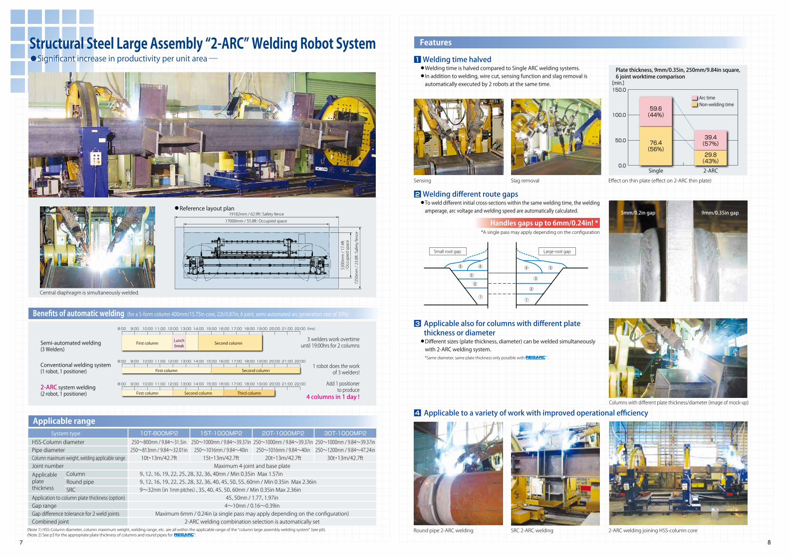
Semi-automated welding(3 Welders)
Conventional welding system(1 robot, 1 positioner)
2-ARC system welding(2 robot, 1 positioner)
3 welders work overtime until 19:00hrs for 2 columns
1 robot does the work of 3 welders!
Add 1 positioner to produce
4 columns in 1 day !Columns with different plate thickness/diameter (image of mock-up)
2-ARC welding joining HSS-column coreRound pipe 2-ARC welding SRC 2-ARC welding
①①
②②
③③
④ ④ ⑤⑤
Small root gap Large root gap
Plate thickness, 9mm/0.35in, 250mm/9.84in square,6 joint worktime comparison
[min.]150.0
100.0
50.0
0.02-ARC
39.4(57%)
Arc time
29.8(43%)
Non-welding time
Single
59.6(44%)
76.4(56%)
Lunchbreak
■ Welding different route gaps● To weld different initial cross-sections within the same welding time, the welding amperage, arc voltage and welding speed are automatically calculated.
7 8
Structural Steel Large Assembly “2-ARC” Welding Robot System● Significant increase in productivity per unit area-
Applicable range
Sensing Slag removal
Handles gaps up to 6mm/0.24in! **A single pass may apply depending on the configuration
5mm/0.2in gap 9mm/0.35in gap
System typeHSS-Column diameterPipe diameterColumn maximum weight, welding applicable rangeJoint number Column Round pipe SRCApplication to column plate thickness (option)Gap rangeGap difference tolerance for 2 weld jointsCombined joint
Maximum 4-joint and base plate
45、50mm / 1.77、1.97in4~10mm / 0.16~0.39in
Maximum 6mm / 0.24in (a single pass may apply depending on the configuration)2-ARC welding combination selection is automatically set
9、12、16、19、22、25、28、32、36、40mm / Min 0.35in Max 1.57in9、12、16、19、22、25、28、32、36、40、45、50、55、60mm / Min 0.35in Max 2.36in9~32mm(in 1mm pitches)、35、40、45、50、60mm / Min 0.35in Max 2.36in
250~800mm / 9.84~31.5in250~813mm / 9.84~32.01in10t・13m/42.7ft
250~1000mm / 9.84~39.37in250~1016mm / 9.84~40in15t・13m/42.7ft
250~1000mm / 9.84~39.37in250~1016mm / 9.84~40in20t・13m/42.7ft
250~1000mm / 9.84~39.37in250~1200mm / 9.84~47.24in
30t・13m/42.7ft
10T-800MP2 15T-1000MP2 20T-1000MP2 30T-1000MP2
● Reference layout plan
Central diaphragm is simultaneously welded.
Features
Benefits of automatic welding (for a S-form column 400mm/15.75in core, 22t/0.87in, 6 joint, semi-automated arc generation rate of 30%)
Effect on thin plate (effect on 2-ARC thin plate)
(Note 1) HSS-Column diameter, column maximum weight, welding range, etc. are all within the applicable range of the “column large assembly welding system” (see p6).(Note 2) See p3 for the appropriate plate thickness of columns and round pipes for .
■ Welding time halved● Welding time is halved compared to Single ARC welding systems.● In addition to welding, wire cut, sensing function and slag removal is automatically executed by 2 robots at the same time.
1
2
■ Applicable to a variety of work with improved operational efficiency 4
■ Applicable also for columns with different plate thickness or diameter
● Different sizes (plate thickness, diameter) can be welded simultaneously with 2-ARC welding system. *Same diameter, same plate thickness only possible with .
Applicableplatethickness
3

11863mm / 38.9ft:Safety fence
8700mm / 28.5ft:Occupied space
6073mm / 19.9ft:Safety fence
3800mm / 12.5ft
:Occupied space
Application example
9 10
Multi-work Structural Steel Connection Welding Robot System● Multi-purpose for high operational efficiency -
Welding points
Applicable range
HSS-Column core SRC core Round pipe core
Connection SRC Connection SRC shaft
Inner diaphragm
SRC Connection (core type)
● Reference layout plan
Type L
Type S (Note 1) Maximum case - work with connection length of 2400mm installed in 2 rows (Note 2) Maximum case - work with column diameter of 500mm installed
● Reference installation points for each type of connection and inner diaphragm and corresponding imageType
S
M
L
Connection work (note1)
2units
3units
6units
Inner diameter (note 2)
4units
6units
13units
Occupied spaceW8700mm×D3800mm×H3420mm(W28.5ft×D12.5ft×H11.2ft)
W11000mm×D3800mm×H3420mm(W36.1ft×D12.5ft×H11.2ft)
W17000mm×D3800mm×H3420mm(W55.8ft×D12.5ft×H11.2ft)
Type M
■ Core welding● Measurement time is eliminated for corner radius sensing, increasing quality.
1
■ Inner diaphragm welding● Applicable to a depth of 300mm/11.81in from the upper surface of the core to the lower surface of the diaphragm (inside metal surface)
3
■ Connection welding● Depending on the matching of the back plate, welding parameters are automatically adjusted to prevent burnt through.
2
■ SRC shaft welding● Interference between the robot and flange is automatically avoided based on the shape of the work enterred and sensing.
4
Features
■ Multi-purpose and operational efficiency achieved● Applicable to respective types of core,connection, inner diaphragm and SRC shaft● Due to continuous operation of differing types or multiple works, long operation times would be possible.
■ Simple input of data for each type of work ● A simple interactive input screen not just for cores but also for all connections, inner diaphragms and SRC shafts● Work measurement and tiresome inputs are lessened to reduce time and prevent input errors.
■ Continuous operation for various works● Using the reserved operation function, numerous works of different types can be set at once, allowing for continuous operation.
1
2
3
(Note 1) the flange aperture requires more than 140mm when using slag automatic removal equipment.
● Core
● SRC shaft
Within 100mm / 3.94in
Flange aperture
Within 800mm / 31.5in
Flange gap separation
1000~3000mm / 39.37~118.11in
Shaft length
6~25mm / 0.24~0.98in
Flange/web thickness
SRC shaft
Type
100~400mm / 3.94~15.75in
Flange width
● Inner diaphragm
9~32mm(in 1mm Pitches)36、40、45、50mm / Min 0.35in Max 1.97in1mm Pitches for 9~32mm / 0.35~1.26in
Inner diaphragm thickness
Inner diaphragm
Type
Within 300mm / 11.81in
Inner diaphragm depth
Below 1000mm / 39.37in
Column core height
200~1000mm / 7.87~39.37inColumn inner diameter175mm / 6.89in
Column core internal diameter
● ConnectionType
300~1000mm / 11.81~39.37in700~1000mm / 27.56~39.37in
Beam structure
Over 120mm / 4.72in
Connection step
9~32mm(in 1mm Pitches)36、40、45、50mm / Min 0.35in Max 1.97in1mm Pitches for 9~32mm / 0.35~1.26in
Flange thickness
100~400mm / 3.94~15.75in
Flange width
S-ConnectionSRC-Connection
250~1100mm / 9.84~43.31in
Diaphragm dimensions
Type
HSS-ColumnRound pipeSRC
Diameter
250~800mm / 9.84~31.5in250~813mm / 9.84~32.01in250~800mm / 9.84~31.5in
9、12、16、19、22、25、28、32、36、40mm / Min 0.35in Max 1.57in9、12、16、19、22、25、28、32、36、40、45、50、55、60mm / Min 0.35in Max 2.36in9~32(in 1mm Pitches)、36、40、45、50、55、60mm / Min 0.35in Max 2.36in
300~3500mm / 11.81~137.8in
LengthApplicable plate thickness
45、50mm / 1.77、1.97in
Applicable to thick plates(option)
(Note 1) Applicable for columns and round pipes with special specifications up to columns 1000mm/39.37in square(Note 2) See p3 for the appropriate plate thickness of columns and round pipes for .

11 12
Full-package Structural Steel Connection Welding Robot System Structural Beam Welding Robot System●Automation of beam welding is achieved-●Connections are “fully” finished by “one set”!-
Welding points
Application example
Welding points
Features Applicable range Features
Connection SRC Connection (core type) SRC Connection Beams
● Outside flange welding ● Inside flange welding ● Web welding
Introduction merit (operation time) Stiffener SP × 3 sheets × both sides + support plate PL × 3 sheets × single side
Applicable range
Inner diaphragm
*SRC connections are also applicable*for ground installation, the applicable range increases. See the applicable range “connection” table on p10.
Specifications
300~800mm / 11.81~31.5inBelow 2400mm / 94.49in
240~650mm / 9.45~25.59in
100~400mm / 3.94~15.75in
Item
Connection heightSize
Diaphragm diameter
Beam flange widthDiaphragm top surface ‒ beam flange top surface
‒ t 19 / 0.75in : over 100mm / 3.94inStep dimension
Below 2.0t / 4409lbMass
Turn welding bead
Beam
1200mm×500mm×19mm×32mm / 47.24in×19.69in×0.75in×1.26in
1000mm×400mm×16mm×28mm / 39.37in×15.75in×0.63in×1.1in
800mm×300mm×14mm×26mm / 31.5inin×11.81in×0.55in×1.02in
SP
16t / 0.63in
14t / 0.55in
12t / 0.47in
PL
16t / 0.63in
14t / 0.55in
12t / 0.47in
Operation time
04:14:24
03:07:54
02:35:30
Arc time (%)
03:05:24(72.9%)
01:58:54(63.3%)
01:26:30(55.6%)
Semi-automatic (%)
10:17:54(30.0%)
06:36:12(30.0%)
04:48:12(30.0%)
*Operation time, arc time and semi-automation are shown in units of time (HH:MM:SS)
Size
Handles beams up to 400~800mm/15.75~31.5in and beam floor position of 1400mm/55.12in.
Includes turn welding (positioner used)
Separation between beam flange from 50mm/1.97in upwards
Through hole diameter 100~600mm/3.94~23.62in
Separation between beam flange from 350mm/13.78in upwards
Applicable points
Beam web × stiffener
Beam flange × stiffener
Beam web × reinforcement plate
Beam web × reinforcement plate/through hole
Beam web × reinforcement (round type) plate
■ Connections are fully completed in one set● A crane is not required for work reversal● Diaphragm×beam flange (inside/outside) and beam web edge material welding is carried out continuously
■ Simple operation● The only inputs are diameter, flange thickness and leg length● Flange thickness and attachment point do not need to be entered
1
2
■ Turn welding ●The flange terminal and scallop interior are sensed and the positional accuracy of the angles are detected to ensure quality turn welding
■ Positioner for beams ●In order to weld stiffener and flange, the beam is rotated by the positioner, and the robot approaches the beam from directly above to reduce residual welding.
●Rotating the beam from front to back does not require a crane thus reducing time.
■ Alternate welding function ●Stiffener welding is done alternately on the front and rear, reducing warping due to the thermal strain of welding.
■ Rotation correction function ●If a part is attached at an angle, the deviation in rotation will be accounted for during welding
●After detecting the terminal position of the component part by sensing, a welding program for the part is made to enable real-time corrections to be made during welding by arc tracking.
1
4
2
3
● With the addition of various positioners, a variety of work can be handled
t 22 / 0.87in- : Diaphragm thickness+ over 120mm / 4.72in
● Reference layout plan ● Reference layout plan
13 14
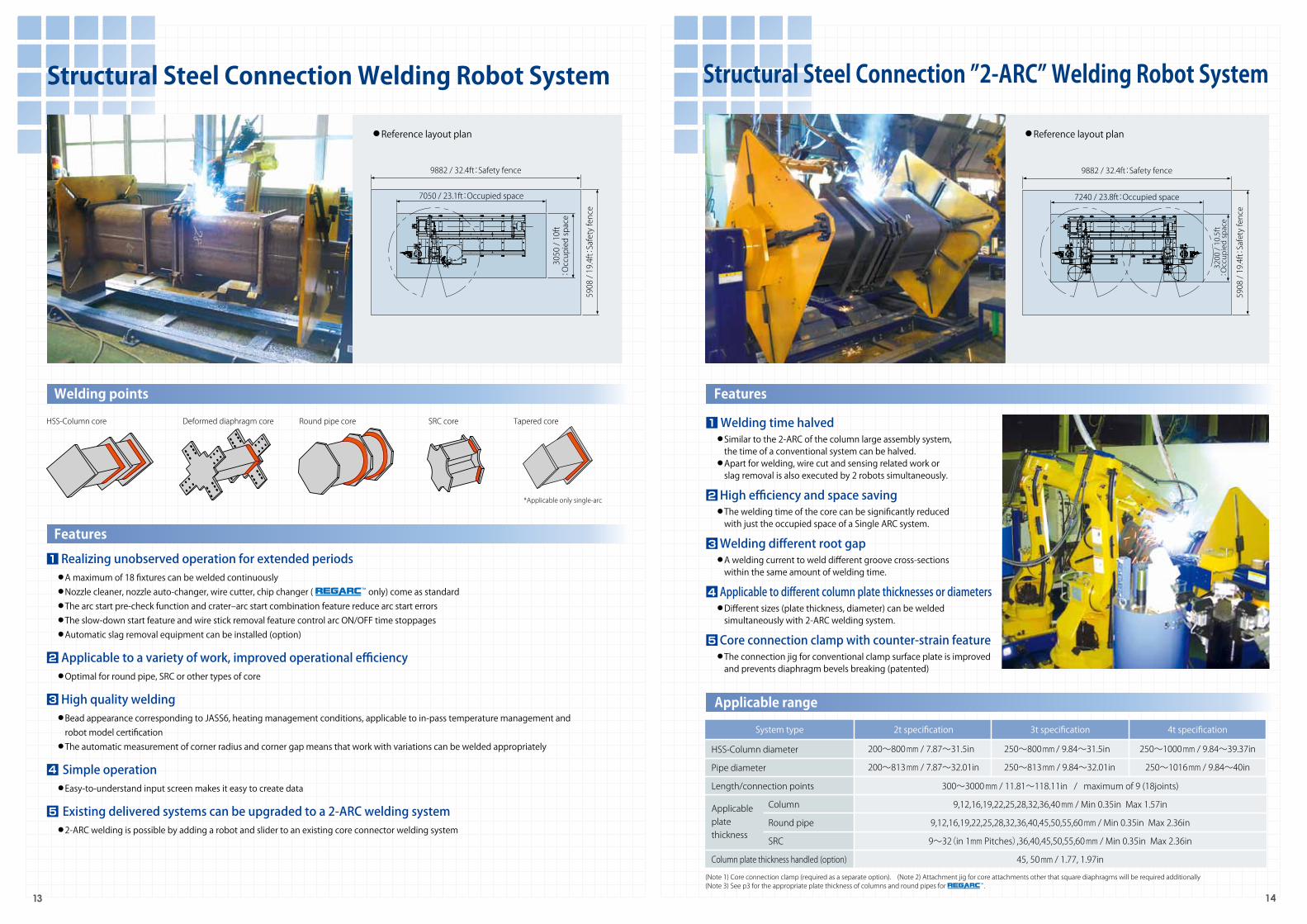
Structural Steel Connection Welding Robot System Structural Steel Connection ”2-ARC” Welding Robot System
HSS-Column core SRC coreDeformed diaphragm core Round pipe core Tapered core
Applicable range
HSS-Column diameter
Pipe diameter
Length/connection points
Column
Round pipe
SRC
Column plate thickness handled (option)
3t specification 4t specification
300~3000 mm / 11.81~118.11in / maximum of 9 (18joints)
9,12,16,19,22,25,28,32,36,40 mm / Min 0.35in Max 1.57in
9,12,16,19,22,25,28,32,36,40,45,50,55,60 mm / Min 0.35in Max 2.36in
9~32(in 1mm Pitches),36,40,45,50,55,60 mm / Min 0.35in Max 2.36in
45, 50 mm / 1.77, 1.97in
250~800 mm / 9.84~31.5in
250~813 mm / 9.84~32.01in
250~1000 mm / 9.84~39.37in
250~1016 mm / 9.84~40in
■ Welding time halved● Similar to the 2-ARC of the column large assembly system, the time of a conventional system can be halved.● Apart for welding, wire cut and sensing related work or slag removal is also executed by 2 robots simultaneously.
■ High efficiency and space saving● The welding time of the core can be significantly reduced with just the occupied space of a Single ARC system.
■ Welding different root gap● A welding current to weld different groove cross-sections within the same amount of welding time.
■ Applicable to different column plate thicknesses or diameters● Different sizes (plate thickness, diameter) can be welded simultaneously with 2-ARC welding system.
■ Core connection clamp with counter-strain feature● The connection jig for conventional clamp surface plate is improved and prevents diaphragm bevels breaking (patented)
9882 / 32.4ft:Safety fence
7050 / 23.1ft:Occupied space
5908 / 19.4ft:Safety fence
3050 / 10ft
:Occupied space
9882 / 32.4ft:Safety fence
7240 / 23.8ft:Occupied space
5908 / 19.4ft:Safety fence
3200 / 10.5ft
:Occupied space
Features
FeaturesWelding points
*Applicable only single-arc
2t specification
200~800 mm / 7.87~31.5in
200~813 mm / 7.87~32.01in
■ Realizing unobserved operation for extended periods● A maximum of 18 fixtures can be welded continuously● Nozzle cleaner, nozzle auto-changer, wire cutter, chip changer ( only) come as standard● The arc start pre-check function and crater‒arc start combination feature reduce arc start errors● The slow-down start feature and wire stick removal feature control arc ON/OFF time stoppages● Automatic slag removal equipment can be installed (option)
■ Applicable to a variety of work, improved operational efficiency● Optimal for round pipe, SRC or other types of core
■ High quality welding● Bead appearance corresponding to JASS6, heating management conditions, applicable to in-pass temperature management and robot model certification● The automatic measurement of corner radius and corner gap means that work with variations can be welded appropriately
■ Simple operation● Easy-to-understand input screen makes it easy to create data
■ Existing delivered systems can be upgraded to a 2-ARC welding system● 2-ARC welding is possible by adding a robot and slider to an existing core connector welding system
1
2
3
4
5
(Note 1) Core connection clamp (required as a separate option). (Note 2) Attachment jig for core attachments other that square diaphragms will be required additionally(Note 3) See p3 for the appropriate plate thickness of columns and round pipes for .
Applicableplatethickness
System type
1
2
3
4
5

● Reference layout plan
5909mm / 19.4ft:Safety fence
1840mm / 6ft:Occupied space
5982mm / 19.6ft:Safety fence
3000mm / 9.8ft:Occupied space
Backing metal overlap
Surface step detection
Diaphragm Beam flange
15 16
Compact Structural Steel Connection Welding Robot System● Small space, big effect !-
Applicable core, connection shape/dimensions
HSS-Column core SRC coreRound pipe core Connection
■ Space saving and easy operation● The equipment only occupies 1.8m × 3.0m / 6ft × 9.8ft !● The robot automatically measures the outer radius of 4 corners by the corner radius sensing function thus eliminating time for measurement and improves quality.● Easy-to-understand input screen makes it easy to create data
■ High quality welding● Bead appearance corresponding to JASS6 and heat control conditions, in-pass temperature management, handling feature and robot model certification are also applicable ● The automatic measurement of corner radius and corner gap means that work with variations can be welded appropriately
■ Connection data can be input easily● Since the input of detailed dimensions is not needed, production time including set-up time can be significantly reduced● Burn through prevention function, surface step applicability function and round-trip multi-pass welding function reduces time and effort during assembly and negate the need for repair welding after robot welding.
■ Realizing unobserved operation for extended periods● Nozzle cleaner, Nozzle auto changer and wire cutter come as standard● Welding of core connection is also possible● The arc start pre-check function and crater ‒ arc start combination feature reduces arc start errors● The slow-down start feature and wire stick removal feature control arc ON/OFF time stoppages● 2 connections positioned to make continuous operation possible
■ Applicable to a variety of work, improving operational efficiency.● Optimal for round pipe, SRC or other types of core● Connection flange welding can also be applied for step connections
Semi-automated welding2 pieces per day
Robot welding6 pieces per day
Average fabrication time3.5hrs per piece
Average fabrication time1.7hrs per piece
8:00
8:00 9:00 10:00 11:00 12:00 13:00 14:00 15:00 16:00 17:00 18:00
9:00 10:00 11:00 12:00 13:00 14:00 15:00 16:00 17:00
Core : 1st piece
Core : 1st piece Core : 2nd piece Core : 3rd piece Core : 4th piece Core : 5th piece Core : 6th piece
Lunch break Core : 2nd piece
*Final desorption within working hours
● Core
300~1000mm / 11.81~39.37in(Butt connection)700~880mm / 27.56~34.65in(Step connection)
● Connection
S form connection,SRC form connection,2 connections placed
Type
240~700mm /9.45~27.56in
Diaphragm dimensions
100~400mm /3.94~15.75in
Flange width
9~32mm(in 1mm Pitches)36、40、45、50mm / Min 0.35in Max 1.97in1mm Pitches for9~32mm / 0.35~1.26in
Flange thickness Beam structure
Over 120mm /4.72in
Connection step
Type
HSS-Column
Round pipe
Tape (option)
SRC form
Diameter
200~800mm / 7.87~31.5in
200~813mm / 7.87~32.01in
250~800mm / 9.84~31.5in
Cross section dimensions:250~700mm / 9.84~27.56inFlange width:100~400mm / 3.94~15.75in
Flange thickness:9、12、16、19、22、25、28、32mm / Min 0.35in Max 2.36inPlate thickness handling:36、40、45、50、55、60mm / Min 1.42in Max 2.36in
9、12、16、19、22、25、28、32、36、40mm / Min 0.35in Max 1.57inPlate thickness handling:45、50mm(option) / 1.77、1.97in
9、12、16、19、22、25、28、32mm / Min 0.35in Max 2.36inPlate thickness handling:36、40、45、50、55、60mm / Min 1.42in Max 2.36in
9、12、16、19、22、25、28、32mm / 0.35in~1.26in
Plate thickness
274~1000mm /10.79~39.37in
Length
● Core connection welding ● Round pipe core welding ● SRC core welding
● Surface step handling function
● Burn through prevention function● Connection welding
SRC Connection (core type) SRC ConnectionTape core
Application example
Welding points
Features
Benefits of automating Subject work : S-form column (400mm / 15.75in core, 16t / 0.75in)
● Surface step sensing and burn through prevention function
Based on the amount of surface step, the welding speed, current, aim position, torch angle, etc will be automatically calculated and welding executed
Depending on the backing metal overlap, the welding speed, current, etc. are automatically calculated and burn through prevented
(Note 1) Core connection clamp (required as a separate option). (Note 2) Attachment jig for core attachments other that square diaphragms will be required additionally(Note 3) See p3 for the appropriate plate thickness of columns and round pipes for .
1
2
3
4
5

○
○
◎
○
○
◎
◎
◎
◎
○
◎
◎
○
○
◎
◎
○
○
○
◎
◎
◎
◎
○
◎
◎
◎
◎
○
○
◎
◎
○
○
○
◎
○
○
○
○
○
◎
○
○
○
○
○
○
○
○
○
◎
○
◎
◎
○
○
○
◎※
◎※
◎※
◎※
◎※
○
◎※
○
◎※
Beam welding
○
◎※
○
○
○
○
○
◎
○
○
◎
◎
◎
○
○
◎
○
○
○
◎
◎
◎
◎
◎
○
○
◎
○
○
◎
◎
○
◎
○
◎
◎
◎
○
○
○
○
◎
○
◎
◎
◎
◎
◎
○
○
○
◎※
◎※
○
◎※
○
◎※
Beam welding
○
◎※
◎
◎
○
○
○
Software nameLarge assembly Multi-work Connections CompactFull-package
※=Applicable through installation of various additional positioners 〇 =Standard specification ◎ =Option
Software quick-glance table
HSS-Column welding
pipe welding
NBFW method
HSS-Column welding
Pipe welding
Connecting welding
SRC core welding
Inner diaphragm welding
NBFW method
Beam welding
Taper core welding (only for Single ARC)
Connecting web welding
SRC shaft welding
Column through column (horizontal) welding
Pipe ring welding
HSS-Column welding plate thickness increased (45, 50mm)
NBFW plate thickness increase (45, 50mm)
Pass split function
Weld overlay adjustment function
2-ARC weld function
Error skip function
Structural Steel navigation
Process reporting software
Constant voltage Constant voltage Constant voltage Constant voltage Constant voltage
◎ Only compatible with welding power supply AB500
17 18
Application
Steel production navigation screen
Support stable operation
■ Structural Steel NavigationUseful for checking production progress and aiding planning and making quotes● Checking production progress : Management of robot welding progress and improving the process prior to weldingDisplays robot operation progress. Production progress can be checked both on the shop floor as well as from the office through a network connection.
● Estimate calculation feature : Eliminates wastage and enables high precision process planning to be madeApart from tact time, wire usage etc. can be calculated to enable high precision process planning and cut down production wastage
■ Process report software (option)Management of input can be executed for the entire welding line thus increasing reliability.● The welding current, arc voltage and welding speed are fed back through the robot during weldingand can be displayed real-time on the PC monitor. After welding, the heat input can be calculated based on the data stored in the PC and a report can be generated.*The software and equipment are not calibrated measurement devices. Exact measurements should be made with separate measuring equipment.
Item
Work name, Column number
Start/end times, Required time
Arc generation time
Wire usage (kg)
Calculated welding length (m)
Gas used (L)
Column diameter, plate thickness
Gap width
Column corner internal radius
Maximum input heat per joint
Current time, elapsed time, Estimated completion time
Current joint name, pass number
Welding order
Remaining wire alarm
Part replacement alarm
List of possible input data
2
1
■ ARCMANTM call function (option)During unmanned operation, the robot's finishing schedule, error messages and operation information can be sent to a designated email address.
■ BCP325T-NBFW method software (option)To weld a cold press steel plate (BCP325T) with increased toughness, a lamination method known as NBFW (Non-Brittle Fracture Welding) shown below is necessary. In addition, with this method, the use of a YGW18 welding wire is necessary and the heat input for the U bead/T bead must be limited to 15 - 22/15 - 25KJ/cm
■ Error skip function (option)When an error such as an arc defect is detected, a skip operation is initiated and then the next joint is welded.
■ Applicable software for maximum input heat 30KJ/cm, 40KJ/cmWelding conditions according to the input heat are automatically generated to match the work.
■ Input heat/pass temperature management softwareA split function is provided for easy management of inter-pass temperature.Applicable also during 2-ARC welding.
■ Corner radius sensing featureThe robot automatically measures the outer radius of 4 corners by the corner radius sensing function thus eliminating time for measurement and improves quality.
■ Corner gap sensing functionThe welding quality can be improved by measuring the gap of the corner parts which are prone to variations from machining process.
■ Arc start pre-check functionBefore welding, the robot automatically checks whether or not the arc can start os as to prevent arc start error.
■ Crater ‒ arc start combined functionFor circumference welding, the corrected information of the sensor position information for the terminal part the arc is reflected in the position of the next pass to improve the appearance of the bead.
■ Wire stick release functionWhen the wire is stuck during the treatment of craters, the robot automatically re-arcs to dislodge the wire thus facilitating the robots continuous operation.
■ Arc retry functionIf the arc does not appear due to surface slag or impurities, the start position is changed and arc start initiation is repeated.
■ Slow down start functionArc starting is improved by smoothly feeding the wire at arc start
■ Scheduled operation functionEven if there are several wires, the data for the next wire can be input into the computer during welding to reduce the robot idle time after welding. In addition, when there are multiple positioners, welding can be carried out on 2 workpieces with just 1 start operation
■ Origin auto-measurement functionFor column large assembly system, the column installation position is automatically measured thus reducing personnel measurement work.
■ Throat thickness height adjustment functionThroat thickness height target value can be slightly adjusted when necessary.
Gap displayCompletion schedule
Work name/ Column number
Welding order
Remainingpass number
Current pass
Wire used, calculated welding length,gas used, welding time
The welding current, arc voltage/welding speed obtained during welding are sent to a PC from the controller and displayed in real-time using the arc monitor software.
The obtained data is collected under the job name and a process report is made
Operation statusdisplay
●●●●●●●
●●●●●●●
●●●●●●●
Input work name and column numberwelding start
Controller
Digital communication
Work
Sensor unit
The process report function can be used in combination with welding power supply AB500 and MP.
Welding power supply AB500
Column management
Joint management
Progress
Other
10
11
12
13
14
15
16
17
3
6
7
4
5
8
9
BCP325T-NBFW software(R part bead appearance of a plate thickness of 36mm)
NBFW lamination pattern
U bead
T bead
5~12mm
8mm以下

19 20
Input ScreenAllows for simple operation
Peripheral equipmentSupporting stable operation
■ Column large assembly welding(Corresponding system : Large assembly 2-ARC/Single ARC)
All work data can be easily viewed in diagram form while inputting
■ Connection welding (Corresponding system : column large assembly, Full-package multi, Compact)
■ SRC shaft welding(Corresponding system : Multi)
■ Inner diaphragm welding(Corresponding system : Full-package multi)
■ Beam welding(Corresponding system : Large assembly, Beam)
■ Core welding (Corresponding system : Large assembly 2-ARC/Single ARC,Core connection 2-ARC/Single ARC, Full-package multi, Compact)
Certified robot type
■ Peripheral equipment for continuous un-supervised operation
■ Welding power supply series AB500(for robot welding only)● Minimum spatter CO2 welding process equipped● Automated switching between and constant voltage● Improved maintainability through digital control
By using 2-types of nozzle lengths, long and short, welding quality can be improved and weld defects due to wind can be prevented.
Improved sensing accuracy improves welding quality
The robot automatically removes slags, which improves continuous operation as well as prevents failures.
As an overall manufacturer of welding products, Kobe Steel, Ltd. develops and produces specific wires for robots.With superior sensing ability compared to normal wire, slags reduction in contribute to superior re-arcing. This is the perfect solid wire for robots.(MG-R series:MG-50R、MG-55R、MG-56R、MG-50R(N)、MG-56R(N))
AB500(for robot welding only) CS500MK2
Kobe Steel, Ltd.'s structural steel welding system for all equipment has obtained the Japanese Robot Association's certification of Architectural steel welding robot and therefore officially approved for industrial use.
Robot specific solid wire MG-R series
CS500MK2(high performance CO2 MAG welding power supply)
● Excellent instant arc start-up
● Superior high speed welding
● Steady arc from low to high currents
Nozzle auto changer Wire cutter Slag automatic clearing equipment
Spatter on the nozzle is automatically cleaned preventing defects such as blow holes.
Chips are changed at the optimal timing to enable extended operation of REGARC™.
Since many cores can be welded continuously, continuous operation time is increased.
Nozzle cleaner Chip changer Core connector clamp
1 2
3 4
5 6

Demo Robot Parts stock TeachingField Service OperatoreducationDEMO
DEMO
DEMO
DEMO
DEMO
DEMO
DEMO
DEMO
DEMO
21 22
System configuration and specifications④ Structural Beam Welding Robot System
Beam specific system6-axis multi-joint welding robot MPBoth grip 1axis, possible load 3000kg / 6614lb
3.9m×17.0m / 12.8ft×42.7ft(6.3m×20.2m / 20.7ft×66.3ft)
Left-right stroke 14.0m / 45.9ft
Robot
Positioner
Occupied space (Safety fence range)
Robot transfer equipment
System type
Reverse Positioner and floor placement type6-axis multi-joint welding robot MPSingle grip 1 axis, possible load 2000kg / 4409lb
4.4m / 14.4ft Deep × 10.7m / 35.1ft Wide (6.1m / 20ft Deep × 14.2m / 46.6ft Wide)
Left-right stroke 8.0m / 26.2ft
③ Full-package Structural Steel Connection Welding Robot System
Robot
Positioner
Occupied space (Safety fence range)
Robot transfer equipment
System type
Type S Type L
Left-right stroke 5.7m / 18.7ft Left-right stroke 14.0m / 45.9ft
3.8m×8.8m / 12.5ft×28.9ft(6.1m×12.0m / 20ft×39.4ft)
Type M6-axis multi-joint welding robot MPBoth grip 1axis, possible load 3000kg / 6614lb
Left-right stroke 8.0m / 26.2ft
3.8m×11.1m / 12.5ft×36.4ft(6.1m×14.2m / 20ft×46.6ft) 3.8m×17.1m / 12.5ft×56.1ft(6.1m×20.2m / 20ft×66.3ft)
② Multi-work Structural Steel Connection Welding Robot System
Robot
Positioner
Occupied space (Safety fence range)
Robot transfer equipment
System type
6-axis multi-joint welding robot MP
10 ton specifications 20 ton specifications 30 ton specifications
Please contact KOBELCO
15 ton specifications
Stroke: left-right 13.0m / 42.7ft, front back 1.15m / 3.8ft
2-ARC:5.3m×17.0m / 17.4ft×42.7ft(7.3m×19.2m / 3.8ft×63ft) / Single ARC:5.3m×16.8m / 17.4ft×55.1ft(7.3m×20.3m / 3.8ft×66.6ft)
① Structural Steel Large Assembly “2-ARC” Welding Robot System
Robot
Occupied space (Safety fence range)
Robot transfer equipment
System type
Welding mode
Utilization rate
Welding equipment
3 ton specifications6-axis multi-joint welding robot MP
Both grip 1axis, possible load 2000kg / 4409lb、3000kg / 6614lb、4000kg / 8818lb
2-ARC:3.5m×7.2m / 11.5ft×23.6ft(5.9m×9.9m / 19.4ft×32.5ft) / Single ARC:3.1m×7.1m / 10.2ft×23.3ft(5.9m×9.9m / 19.4ft×32.5ft)
Left-right stroke 3.0m / 9.8ft
⑤ Structural Steel Connection Welding Robot System
Robot
Positioner
Occupied space (Safety fence range)
Robot transfer equipment
System type 2 ton specifications 4 ton specifications
System type
Robot
PositionerOccupied space (Safety fence range)
6-axis multi-joint welding robot MPSingle grip 1 axis, possible load 650kg / 1433lb、1000kg / 2205lb
1.8m×3.0m / 5.9ft×9.8ft(6.0m×5.9m / 19.7ft×19.4ft)
⑥ Compact Structural Steel Connection Welding Robot System1 ton specificationsStandard specifications(650kg / 1433lb)
mode/ set voltage mode
Using 450A-100% water cooled torch
AB500
set voltage mode
Using 500A-100% water cooled torch
CS500MK2
KOBELCO Global Services Network
ROLAN ROBOTICS B.V.AP ZWAAG, The Netherlands
PT. UNGGUL SEMESTABekasi, Indonesia
KOBE STEEL, LTD. WELDING BUSINESSFujisawa, Japan
KOBE WELDING SHANGHAI CO., LTD. (KWSH) Shanghai, P.R. of China
FACTORY AUTOMATION SYSTEMSAtlanta, USA
TANGSHAN KAIYUAN ROBOT SYSTEM CO., LTD.Tangshan, P.R. of China
SHINWON TECH. Changwon, Korea
KOBE TRADING (SHANGHAI) CO., LTDChengdu, China
KOBELCO WELDING OF AMERICA INC.(KWAI) Houston, USA
THAI-ESCORP LTD. Sriracha,Thailand
PRIMO AUTOMATION SYSTEMS(P) LTD.Chennai, India
(Note 1)The installation method for the safety fence mentioned above is given in JIS B 9707 (Machine safety - Safety distances for preventing upper limbs reaching dangerous areas-)(Note 2)Safety fence specifications: 1800mm/70.87in or more from the floor level
● Peripheral equipment, welding specifications (① - ⑥ common)
Peripheral equipment
Welding specifications
Welding wire : solid wire MG-50R、MG-50R(N)、MG-55R、MG-55、MG-56R、MG-56R(N)、MG-56、MG-400FR 1.2mmφSh i e l d g a s : CO2 100%Welding posture : Column large assembly... downward, horizontal fillet, level, ceiling... downward, horizontal fillet, downward fillet, core connection/space saving type core/joint combined... downward
Nozzle cleaner, air cleaner, wire cutter (air drive type), nozzle auto-changer (with wire brush cleaning feature), Computerized slag auto-removal equipment, chip changer (not space saving type, powered series)

16031000F
WELDING BUSINESS
http://www.kobelco.co.jp/english/welding/International Sales & Marketing Section 9-12, Kita-Shinagawa 5-chome, Shinagawa-ku, TOKYO 141-8688, JAPAN +81-3-5739-6332 (Tel) +81-3-5739-6960 (Fax)
The products and services represented in this catalog are governed by the export restrictions of the Japanese Foreign Exchange and Foreign Trade Act. A Japanese government issued export permit may be necessary to export outside Japan.If export is intended, kindly consult Kobe Steel, Ltd. Welding Business and/or its sales offices. Please be advised in advance that we reserve the right to confirm the export destination includ-ing the nature and/or intended use of our products and services at the said destination.
STRUCTURAL STEEL WELDING ROBOT SYSTEM
WELDING ROBOTSTRUCTURAL STEEL
WELDING ROBOT SYSTEM
WELDING ROBOT