Embed Size (px)
Citation preview

International Journal of Engineering Science Invention (IJESI)
ISSN (Online): 2319 – 6734, ISSN (Print): 2319 – 6726
www.ijesi.org ||Volume 7 Issue 1|| January 2018 || PP.09-20
www.ijesi.org 9 | Page
Structural Stability And 2d Finite Element Analysis of Concrete
Gravity Dam
Khalid Dawlatzai1, Dr. Manju Dominic
2
1PG Student, Department of Civil Engineering, FET, Manav Rachna International Institutions,Haryana, India..
2Associate Professor, Department of Civil Engineering, FET, Manav Rachna International Institutions,
Haryana, India.
Corresponding Author:Khalid Dawlatzai
Abstract:Concrete Gravity Dams are important lifeline structures and represent the fragrance of people’s
standard of living. Dam structures that span navigable waterways are inherently at a risk for seismic vibrations
and as such they must be designed to resist these vibrations. These are very complex structures and subjected to
various types of forces both static and dynamic in nature. Conventional 2 dimensional methods are used for the
preliminary analysis and to check the stability criteria for dam structures. Provided the results obtained from
such analysis are over-estimated, it is still useful for the preliminary analysis. In this work a 2 dimensional
stability analysis of a non-overflow section of the Koyna dam having maximum height of 103 m and base width
of 70 m is done first using the Gravity method of analysis which is a rational analysis method. Various forces
acting on the dam body including vertical and horizontal earthquake forces are worked out and the stresses are
manually calculated at different points, i.e. at heel and toe. Considering the same cross sectional dimensions
and material properties a 2D finite element model of the dam is simulated using ANSYS APDL R.18.2. The
stress results found through both approaches are tabulated and are compared for the accuracy of manual
calculations. Dam-foundation-reservoir interaction is neglected and the dam is assumed to be fixed at the base.
Earthquake force is the inertia force induced due to acceleration caused by earthquake, and this acceleration is
considered as a fraction of Peak Ground Acceleration (PGA) applied to the dam. The dam material is assumed
to be elastic and isotropic. The worst conditions for earthquake forces are considered and two cases i.e.
reservoir empty and reservoir full conditions are considered.
Keywords: Gravity dam: ANSYS; stability analysis; 2D Finite Element Analysis; gravity method.
------------------------------------------------------------------------------------------------------------------------------ ---------
Date of Submission: 20-01-2018 Date of acceptance: 05-02-2018
----------------------------------------------------------------------------------------------------------------------------- ----------
I. Introduction A gravity dam is a solid structure, made of concrete or masonry, constructed across a river to create a
reservoir on its upstream. The section of the gravity dam is approximately triangular in shape, with its apex at its
top and maximum width at bottom. The section is so designed and shaped that its weight is sufficient to ensure
stability against the effects of all imposed forces. This type of structure is most durable and solid, and requires
very little maintenance. Such dams may be constructed of masonry or concrete. However, concrete gravity dams
are preferred these days and mostly constructed. They can be constructed with ease on any dam site, where there
exists a natural foundation strong enough to bear the enormous weight of the dam. Such a dam is generally
straight in plan, although sometimes it may be slightly curve. The line of the upstream face of the dam, or the line
of the crown of the dam if the upstream face is slopping, is taken as the reference line for the layout purposes and
is known as the base line of the dam or the axis of the dam. When suitable conditions are available such dams can
be constructed to the great heights. The highest concrete gravity dam in the world is Grand Dixence Dam in
Switzerland (284 m) height and Bhakra Dam in India (226 m) [1]
. The ratio of base width to the height of these
dams is less than 1:1.
II. Typical Cross-Section The basic shape of a concrete gravity dam is triangular in section (Fig. 1A), with the top crest often
widened to provide a roadway (Fig. 1B) [2]
. The increasing width of the section towards the base is logical since
the water pressure also increases linearly with depth as shown in Fig. 1A. In the figure, h is assumed as the depth
of water and 𝛾ℎ is the pressure at base, where γ is the unit weight of water (9.81 𝐾𝑁/𝑚³), W is the weight of the
dam body. The top portion of the dam (Fig. 1B) is widened to provide space for vehicle movement.

Structural Stability And 2D Finite Element Analysis Of Concrete Gravity Dam
www.ijesi.org 10 | Page
Fig. 1: Concrete gravity dam section
III. Froces Acting On Concrete Gravity Dam Technically a concrete gravity dam derives its stability from the force of gravity of the materials in the
section and hence the name. The gravity dam has sufficient weight so as to withstand the forces and the
overturning moment caused by the water impounded in the reservoir behind it.It transfers the loads to the
foundations by cantilever action and hence good foundations are prerequisite for the gravity dam.
The forces that give stability to the dam include:
Weight of the dam
Thrust of the tail water
The forces that try to destabilize the dam include:
Reservoir water pressure
Uplift pressure
Forces due to waves in the reservoir
Ice pressure
Temperature stresses
Silt pressure
Seismic forces
Wind pressure
3.1 Weight of The Dam
The weight of the dam body and its foundation is the major resisting force. In two dimensional analysis
of a gravity dam, a unit length of the dam is considered. The cross-section can then be divided into rectangles and
triangles. The weight of each along with their centers of gravity can be determined. The resultant of all these
downward forces will represent the total weight of the dam acting at the center of gravity of the dam.
3.2 Water Pressure
Water pressure is as shown in Fig. 1 varying linearly form zero at the top to its maximum value at the
base. The resultant force due to this external water =1
2𝛾𝑤ℎ
2 acting at a distance ℎ 3 from the base. When the
upstream face is partly vertical and partly inclined the resulting water force can be resolved into horizontal
component𝑃ℎ and vertical component𝑃𝑣 . The horizontal component equals 1
2𝛾𝑤ℎ
2 acting at ℎ 3 from the base,
and vertical component is equal to the weight of the water stored above the slanting surface acting at the center of
gravity of the area.Similarly, if there is tail water on the downstream side, it will also be resolved into horizontal
and vertical components.
3.3 Uplift Pressure
Water seeping through the pores, cracks and fissures of the foundation material, and water seeping
through dam body and then to the bottom through the joints between the body of the dam and its foundation at the
base exerts an uplift pressure on the base of the dam. It is the second major external force and must be accounted
for in all calculations. Such an uplift force virtually reduces the downward weight of the dam and hence, acts
against the dam stability.
The amount of uplift is a matter of research and the present recommendations which are followed, are
those suggested by United States Bureau of Reclamation (USBR) [3]
. According to these recommendations, the
uplift pressure intensities at the heel and toe should be taken equal to their respective hydrostatic pressures joined
by a straight line in between. When drainage galleries are provided to relive the uplift, the recommended uplift at
the face of gallery is equal to the hydrostatic pressure at toe (𝛾𝑤ℎ′) plus 1 3 rd the difference of the hydrostatic
pressures at the heel and at the toe. Where, ℎ′is the height of tail water.

Structural Stability And 2D Finite Element Analysis Of Concrete Gravity Dam
www.ijesi.org 11 | Page
3.4 Ice Pressure
The ice which may be formed on the water surface of the reservoir in cold countries, may sometimes
melt and expand. The dam has to resist the thrust exerted by the expanding ice. This force acts linearly along the
length of the dam and at the reservoir level. The magnitude of this force varies from 250 to 1500 𝐾𝑁 𝑚2
depending upon the temprature variations. On an average, a value of 500 𝐾𝑁 𝑚2 may be allowed under ordinary
conditions.
3.5 Silt Pressure
Silt gets deposited against the upstream face of the dam. If ℎ is the heigth of silt deposited, then the forces exreted
by this silt in addition to external water pressure can be represented by Rankine’s formula as:
𝑃𝑠𝑖𝑙𝑡 = 12 𝛾𝑠𝑢𝑏 ℎ
2𝐾𝑎 (1)
Where,
𝐾𝑎 Is the coefficient of active earth pressure of silt =1−sin 𝜑
1+sin 𝜑 , 𝜑 is the angle of internal friction of soil, and
cohession is neglected.
𝛾𝑠𝑢𝑏 is the submerged unit weight of material.
ℎ is the height of silt deposited.
If the upstream face is inclined, the vertical weight of the silt deposited on the slope also acts as a vertical force. It
is recommended that the submerged density of silt for calculating horizontal pressure may be taken as1360𝐾𝑔/𝑚³. Equivalently, for calculating vertical force, the same may be taken as1925 𝐾𝑔/𝑚³.
3.6 Wave Pressure
Waves are generated on the surface of the reservoir by the blowing winds, which causes a pressure towards the
downstream side. Wave pressure depends upon the wave height (ℎ𝑤 ). The maximum pressure intensity due to
wave action may be given by:
𝑃𝑤 = 2.4𝛾𝑤ℎ𝑤 (2)
And acts at ℎ𝑤/2 meters above the still water surface.
ℎ𝑤 = 0.032 𝑉 ∙ 𝐹 + 0.763 − 0.271(𝐹)3
4 (3)
For 𝐹 < 32 𝑘𝑚 and For 𝐹 > 32 𝑘𝑚
ℎ𝑤 = 0.032 𝑉 ∙ 𝐹 (4)
Where,ℎ𝑤 is the height of water from the top of crest to bottom of rough in meters, 𝑉 wind velocity in𝐾𝑚 ℎ𝑟 ,
and 𝐹is the Fench or straight length of water expanse in 𝐾𝑚.
3.7 Earthquake Forces
An earthquake produces waves which are capable of shaking the earth upon which the dam is resting, in every
possible direction. The effect of an earthquake is, therefore, equivalent to imparting an acceleration to the
foundation of the dam in the direction in which the wave is travelling at the moment. Earthquake wave may move
in any direction, and for design purposes it has to be resolved into vertical and horizontal components.
3.7.1 Effect of Vertical Acceleration (av )
A vertical acceleration may either act downward or upward. When it is acting upward direction, then the
foundation of the dam will be lifted upward and become closer to the body of the dam, and thus the effective
weight of the dam will increase and the stress developed will increase.
When the acceleration is acting downward, the foundation shall try to move downward away from the dam body;
thus reducing the effective weight and the stability of the dam and is the worst case for design.Then, the effective
weight of the dam.
= 𝑊 −𝑊
𝑔∙ 𝑘𝑣 ∙ 𝑔 = 𝑊[1 − 𝑘𝑣] (5)
Where,𝑊 is the total weight of the dam, 𝑘𝑣 is the fraction of gravity adopted for vertical acceleration.
In other words, vertical acceleration reduces the unit weight of the dam material and that of water to (1 − 𝑘𝑣)
times their original unit weight.
3.7.2 Effect of Horizontal Acceleration (ah)
Horizontal acceleration may cause the following two forces:
3.7.2.1 Hydrodynamic Pressure: Horizontal acceleration acting towards the reservoir causes a momentary
increase in the water pressure, as the foundation and dam accelerate towards the reservoir and the water resists the
movement owing to its inertia. The extra pressure exerted by this process is known as hydrodynamic pressure.

Structural Stability And 2D Finite Element Analysis Of Concrete Gravity Dam
www.ijesi.org 12 | Page
According to Zanger’s formula [4]
, hydrodynamic pressure is;
𝑃𝑒 = 𝐶𝑚𝑘ℎ ∙ 𝛾𝑤 ∙ 𝐻(6)
The resultant force due to this pressure is
𝑃𝑒 = 0.726𝐶𝑚𝑘ℎ ∙ 𝛾𝑤 ∙ 𝐻2(7)
Where; 𝐶𝑚 = 0.735(𝜃
90°) is the maximum value of pressure co-efficient for a given constant slope, 𝜃is the angle
in degrees, which the upstream face makes with the horizontal, 𝑘ℎ is the fraction of gravity adopted for horizontal
acceleration, H is the total height of the dam.
The moment of this force about the base is given as:
𝑀𝑒 = 0.412𝑃𝑒 ∙ 𝐻(8)
It is further stated that if the upstream face is partly inclined which does not extend to more than half the
depth of the reservoir, it can be taken as vertical. If the slope extends to more than half depth the overall slope up
to the whole height is taken as the value of 𝜃 in the equation above.
3.7.3 Horizontal Inertia Force:In addition to exerting the hydrodynamic pressure, the horizontal acceleration
produces an inertia force into the body of the dam. This force is generated in order to keep the body and the
foundation of the dam together as one piece. The direction of the produced force will be opposite to the
acceleration imparted by the earthquake.
Since an earthquake may impart either upstream or downstream acceleration, we have to choose the direction of
this force in our stability analysis of dam structure in such a way that it produces most unfavorable effects under
the considered condition.
Under reservoir empty condition, earthquake forces produce effects which may cause slight tension near the toe;
and hence stability analysis for reservoir empty case may be carried out only on the basis of weight of the dam by
ignoring earthquake forces and keeping the section free from tension. However, for all precise designs, these
forces must be fully considered.
The amount of this horizontal inertia force is given
𝑊
𝑔 ∙ 𝑘ℎ ∙ 𝑔 = 𝑊 ∙ 𝑘ℎ (9)
This force should be considered to be acting at the center of gravity of the mass, regardless of the shape of the
cross section, and it acts horizontally downstream in worst case, for reservoir full condition.
IV. Literature Review There are a large number of concrete dams in the world. Some of them are in seismically active areas.
The analysis of dams is a complex problem due to the dam-reservoir interaction. An important factor in the
design of dams in seismic regions is the effect of hydrodynamic pressure exerted on the face of dam as a result of
earthquake ground motions. The seismic response of a gravity dam is influenced by its interaction with reservoir.
The DESIGN MANUAL FOR CONCRETE GRAVITY DAMS (1976) published by the United States
Bureau of Reclamation (USBR), Chapter III Gravity dams (2016) by Federal Energy Regulatory Commission
(FERC), Criteria for Design of Solid Gravity dams; IS: 6512-1984 and many other guidelines are available
worldwide for the design and analysis of concrete gravity dams.
In case of conventional analysis for static loads, criteria for structural stability have to be checked for following
modes of failure:
That it be safe against overturning at any horizontal plane within the structure, at the base, or at a plane
below the base.
That it be safe against sliding on any horizontal or near-horizontal plane within the structure at the base or on
any rock seam in the foundation.
That the allowable unit stresses in the concrete or in the foundation material shall not be exceeded.
Characteristic locations within the dam in which a stability criteria check should be considered include
planes where there are dam section changes and high concentrated loads. Large galleries and openings within the
structure and upstream and downstream slope transitions are specific areas for consideration.
Traditionally concrete gravity dams have been analyzed and designed by a procedure suggested by
Westergaard. Westergaard (1933), introduced an approach to determine approximately the linear response of the
dam-reservoir system by a number of masses that are added to the dam body. The method, which is usually
applied in 2 dimensional analysis, treats the dam as a rigid structure on a rigid foundation and assumes that the
hydrodynamic effect on a rigid dam is equivalent to the inertial force resulting from a mass distribution added on
the dam body.

Structural Stability And 2D Finite Element Analysis Of Concrete Gravity Dam
www.ijesi.org 13 | Page
Chopra, A.K. (1980), proposed a simplified analysis procedure for dynamic analysis of concrete gravity
dams which include only the fundamental vibration mode in calculating the design forces. In his study, the
gravity dam is considered as two-dimensional finite element system, the reservoir as an infinite continuum in the
upstream direction with constant depth, and the foundation as a finite element system or viscoelastic half space.
This simplified method can be conveniently used in preliminary design of large gravity dams or in the final
design of small dams. In this method the interaction effects between the flexible dam and reservoir have been
included, but dam foundation interactions have been disregarded.
A two-stage procedure has been proposed by Løkke (2013) for the elastic analysis phase of seismic
design and safety evaluation of concrete gravity dams: (i) Response Spectrum Analysis (RSA) and (ii) Response
History Analysis (RHA) of a finite element idealization of the dam monolith. Both analysis procedures include
the effects of dam-water foundation interaction. These procedures are added to computer software EAGD-84 and
MATLAB program.
Leclerc et. al. (2002) presents the main features and organization of CADAM, a computer program that
has been developed for the static and seismic stability evaluations of concrete gravity dams. CADAM is based on
the gravity method using rigid body equilibrium and beam theory to perform stress analysis, compute crack
lengths, and safety factors.
IS 1893-1984, Criteria for earthquake resistant design of structures, suggests the following methods for the
determination of earthquake forces on concrete gravity dams;
Seismic coefficient method (for dams up to 100m height)
Response spectrum method (for dams of height greater than 100m)
V. Scope And Objectives In this work a 2 dimensional stability analysis of the Koyna dam having maximum height of 103 m is
done first using the Gravity method of analysis which is a rational analysis method. Various forces acting on the
dam body including vertical and horizontal earthquake forces are worked out and the stresses are manually
calculated at different points, i.e. at heel and toe. Considering the same cross sectional dimensions and material
properties a 2D finite element model of the dam is simulated using ANSYS APDL R.18.2. The stress results
found through both approaches are tabulated and are compared for the accuracy of manual calculations. Dam-
foundation-reservoir interaction is neglected and the dam is assumed to be fixed at the base. Inertia forces induced
due to acceleration caused by earthquake, and these accelerations are considered as a fraction of Peak Ground
Acceleration (PGA) and are applied to the dam. The dam material is assumed to be elastic and isotropic. The
worst conditions for earthquake forces are considered and two cases i.e. reservoir empty and reservoir full
conditions are considered.
VI. Gravity Method or Two Dimensional Stability Analysis The preliminary analysis of gravity dams can be made easily by isolating a typical cross-section of the
dam of a unit width. This section is assumed to behave independently of the adjoining sections. In other words,
the dam is considered to be made up of a number of cantilevers of unit width each, which act independently of
each other. This assumption of independent functioning of each section disregards the beam action in the dam as
a whole.
If the vertical transverse joints of the dam are not grouted or keyed together, this assumption is nearly
true. Hence, for wide U-shaped valleys, where transverse joints are not generally grouted, this assumption is
nearly satisfied. But for narrow V-shaped valleys, where the transverse joints are generally keyed together and the
entire length of the dam acts monolithically as a single body, this assumption may involve appreciable errors. In
such cases, preliminary designs may be done by gravity method and precise final designs may be carried out by
three dimensional methods.
The stability analysis of a dam section is carried out to check the safety with regard to
Rotation and overturning
Translation and sliding
Overstress and material failure.
Gravity method is based on beam theory and is applicable if the following assumptions are satisfied:
The dam is considered to be composed of a number of cantilevers, each of which is 1 m thick and each of
which acts independent of the other.
No loads are transferred to the abutments by beam action.
The foundation and the dam behave as a single unit i.e. the joint being perfect.
The materials in the foundation and body of the dam are isotropic, and homogenous.
The stresses developed in the foundation and body of the dam are within elastic limits.
No movement of the foundations are caused due to transference of load.

Structural Stability And 2D Finite Element Analysis Of Concrete Gravity Dam
www.ijesi.org 14 | Page
Small openings made in the body of the dam do not affect the general distribution of stresses and they only
produce local effects.
The stability of the dam can be analyzed in the following steps:
Consider unit length of the dam.
Work out the magnitude and direction of all the vertical forces acting on the dam and their algebraic sum,
i.e. 𝑉.
Similarly work out all the horizontal forces and their algebraic sum, i.e. 𝐻.
Determine the lever arm of all the forces about the toe.
Determine the moment of all forces about the toe and find out the algebraic sum of all those moments, i.e.
𝑀.
Find out the location of the resultant force by determining its distance from the toe. 𝑋 = 𝑀
𝑉 (10)
Find out the eccentricity (e) of the resultant by
𝑒 =𝐵
2− 𝑋(11)
It must be less than 𝐵 6 in order to ensure that no tension is developed anywhere in the dam.
Determine the maximum and minimum normal stresses at heel and toe using
𝑃𝑚𝑎𝑥 /𝑚𝑖𝑛 = 𝑉
𝐵(1 ±
6𝑒
𝐵) (12)
Determine the maximum normal stresses i.e. principle stresses at the toe and the heel using
𝜎𝑎𝑡𝑡𝑜𝑒 = 𝑃𝑣𝑠𝑒𝑐2 ∝ − 𝑃′ − 𝑃𝑒
′ 𝑡𝑎𝑛2 ∝(13)
Where, 𝑃𝑣 is the intensity of normal pressure at the base of the dam, 𝑃′ is the intensity of pressure on the
downstream face exerted by tail water, 𝑃𝑒′ is the hydrodynamic pressure exerted by tail water during an
earthquake moving towards reservoir.
∝ is the angle made by downstream face and vertical.
𝜎𝑎𝑡ℎ𝑒𝑒𝑙 = 𝑃𝑣 ∙ 𝑠𝑒𝑐2𝜑 − 𝑃′ + 𝑃𝑒
′ 𝑡𝑎𝑛2𝜑(14)
𝜏 = (𝑃𝑣 − 𝑃′)𝑡𝑎𝑛 ∝ (15)
Where, 𝜑 is the angle which made by upstream face and vertical.(They should not exceed maximum allowable
values).
Determine the Factor of Safety against Overturning
F. S. O = 𝑀𝑅
𝑀𝑜(16)
𝑀𝑅 is the summation of stabilizing moment and 𝑀𝑜 is the summation of overturning moment. The factor of
safety against overturning (F.S.O.) generally varies from 1.5 to 2.
Determine the Factor of Safety against Sliding, using sliding factor as:
S.F.F. =𝜇 𝑉
𝐻(17)
Where, 𝜇 𝑉is the shear resistance in which 𝑉 is the total vertical forces; 𝜇 is the coefficient of friction be-
tween the dam base and foundation, which varies from 0.65 - 0.75; and 𝑉is the total external horizontal forces.
In low dams, the safety against sliding should be checked only for friction, but in high gravity dams, for economic
precise designs, the shear strength of the joint, which is an additional shear resistance, must also be considered. If
this shear resistance of the joint is considered, then the equation for factor of safety against sliding which is
measured by shear friction factor (S.F.F.) becomes:
S.F.F. =𝜇 𝑉+𝐵𝑞
𝐻(18) Where, q is the average shear strength of the joint which varies from about 1400
KN/m2for poor rocks to about 4000 KN/m
2 for good rocks.
For the stability analysis using gravity method two cases are considered i.e. reservoir empty case and
reservoir full case. Material properties used in the Koyna dam are listed in Table 1.
Table 1: Material properties used in Koyna dam [5]
Young’s modulus 31027 Mpa
Poisson’s ratio 0.15
Density 25.5 KN/m3
Compressive initial yield stress 13 Mpa
Compressive ultimate stress 24.1 Mpa
Tensile failure stress 2.9 Mpa
Structural Stability And 2D Finite Element Analysis Of Concrete Gravity Dam
www.ijesi.org 15 | Page
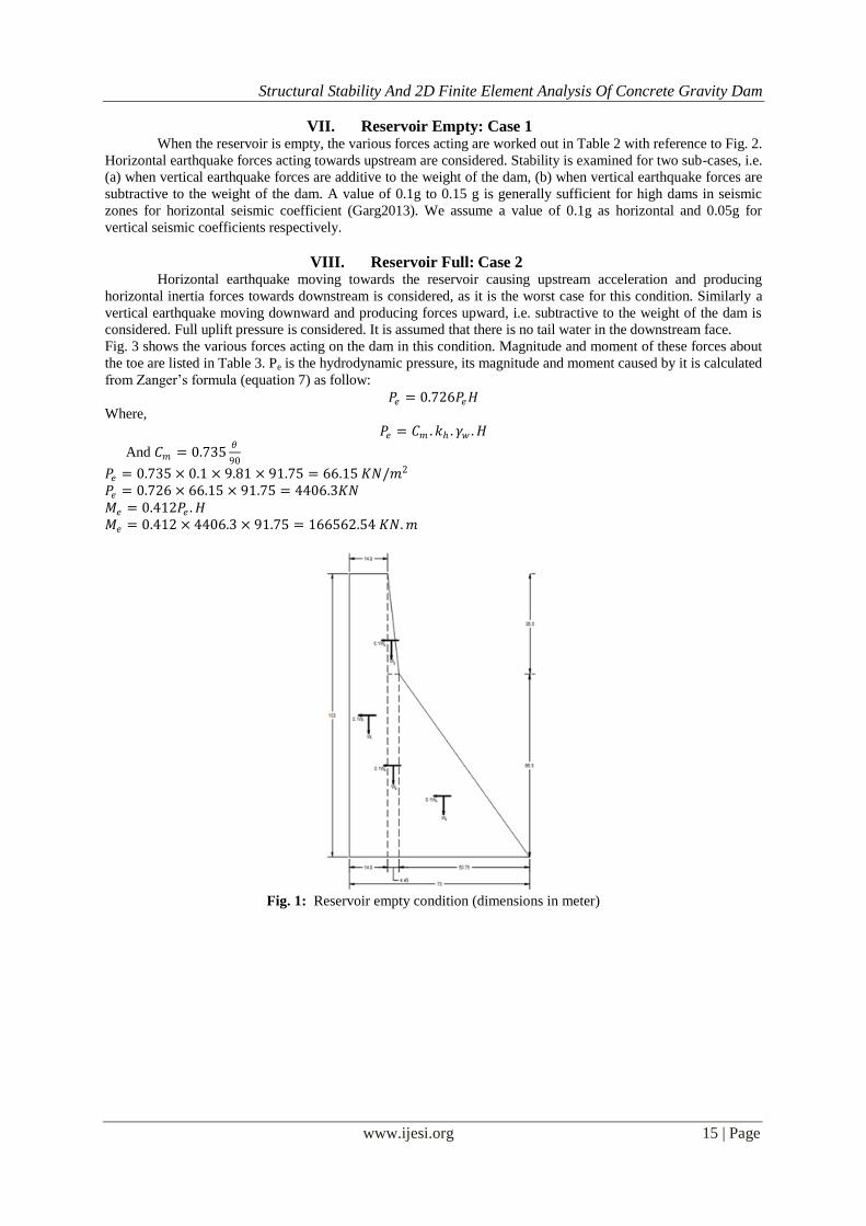
VII. Reservoir Empty: Case 1 When the reservoir is empty, the various forces acting are worked out in Table 2 with reference to Fig. 2.
Horizontal earthquake forces acting towards upstream are considered. Stability is examined for two sub-cases, i.e.
(a) when vertical earthquake forces are additive to the weight of the dam, (b) when vertical earthquake forces are
subtractive to the weight of the dam. A value of 0.1g to 0.15 g is generally sufficient for high dams in seismic
zones for horizontal seismic coefficient (Garg2013). We assume a value of 0.1g as horizontal and 0.05g for
vertical seismic coefficients respectively.
VIII. Reservoir Full: Case 2 Horizontal earthquake moving towards the reservoir causing upstream acceleration and producing
horizontal inertia forces towards downstream is considered, as it is the worst case for this condition. Similarly a
vertical earthquake moving downward and producing forces upward, i.e. subtractive to the weight of the dam is
considered. Full uplift pressure is considered. It is assumed that there is no tail water in the downstream face.
Fig. 3 shows the various forces acting on the dam in this condition. Magnitude and moment of these forces about
the toe are listed in Table 3. Pe is the hydrodynamic pressure, its magnitude and moment caused by it is calculated
from Zanger’s formula (equation 7) as follow:
𝑃𝑒 = 0.726𝑃𝑒𝐻 Where,
𝑃𝑒 = 𝐶𝑚 .𝑘ℎ . 𝛾𝑤 .𝐻
And 𝐶𝑚 = 0.735𝜃
90
𝑃𝑒 = 0.735 × 0.1 × 9.81 × 91.75 = 66.15 𝐾𝑁/𝑚2
𝑃𝑒 = 0.726 × 66.15 × 91.75 = 4406.3𝐾𝑁
𝑀𝑒 = 0.412𝑃𝑒 .𝐻
𝑀𝑒 = 0.412 × 4406.3 × 91.75 = 166562.54 𝐾𝑁.𝑚
Fig. 1: Reservoir empty condition (dimensions in meter)

Structural Stability And 2D Finite Element Analysis Of Concrete Gravity Dam
www.ijesi.org 16 | Page
Table 2: Forces acting on the dam in reservoir emptycase
Fig. 3: Reservoir full condition

Structural Stability And 2D Finite Element Analysis Of Concrete Gravity Dam
www.ijesi.org 17 | Page
Table 3: Forces acting on the dam in reservoir full case
IX. 2D FEM Modelling Of The Dam Section Using Ansys APDL R18.2 ANSYS is a general purpose finite element modeling package for numerically solving a wide variety of
problems. These problems include: static/dynamic structural analysis (both linear and non-linear), heat transfer
and fluid problems, as well as acoustic and electro-magnetic problems.
A 2D finite element model of the dam is simulated using ANSYS ADPL. Material properties and the
dimensions of the section are as stated for gravity method. All nodes along the base are restrained i.e. all degrees
of freedom are restrained so that the fixity at the base be simulated. The element type used for the modelling is
PLANE183, Plane183 is a higher order 2-D, 8-node or 6-noded element like in Fig.4. Plane183 has quadratic
displacement behavior and is well suited to modeling irregular meshes. This element is defined by 8 nodes or 6-
nodes, having two degrees of freedom at each node: translations in the nodal x and y directions. The element may
be used as a plane element (plane stress, plane strain and generalized plane strain) or as an axi-symmetric
element. This element has plasticity, hyper-elasticity, creep, stress stiffening, large deflection and large strain
capabilities. It also has mixed formulation capability for simulating deformations of nearly incompressible
elastoplastic materials and fully incompressible hyper-elastic materials.

Structural Stability And 2D Finite Element Analysis Of Concrete Gravity Dam
www.ijesi.org 18 | Page
Fig. 4: Plane 183 solid
9.1 Step by Step Procedure forFEM Modelling
In general, a finite element solution may be broken into the following three stages.
9.1.1 Preprocessing: defining the problem:the major steps in preprocessing are:
Define keypoints/lines/areas/volumes
Define element type and material/geometric properties
Mesh lines/areas/volumes as required
9.1.2 Solution: assigning loads, constraints and solving:here we specify the loads (point or pressure),
constraints (translational and rotational) and finally solve the resulting set of equations.
9.1.3 Post-processing: further processing and viewing of the results:in this stage one may wish to see:
Lists of nodal displacements
Element forces and moments
Deflection plots
Stress contour diagrams
Following path is followed stepwise to do the FEM modelling and analysis:
Preferences>>Structural>>Ok
Preprocessor>>Element type>>Add/Edit/Delete>>Solid>>8 node183>>Ok
Preprocessor>>Material Props>>Add/Material Models>>Structural>>>>Ok
Preprocessor>>Modelling>>Create>>Keypoints>>In Active CS>>Ok
Preprocessor>>Modelling>>Create >>Area>>Arbitrary>>Through KPs>>Ok
Preprocessor>>Mesh>>Areas >>Mapped>>By corners>> Ok
Preprocessor>>Loads>>Define>>Apply>>Structural>>Displacement>> On Nodes>>Ok
Preprocessor>>Loads>>Define>>Apply>>Structural>>Inertia>> Gravity>>Ok
Solution>>Solve>>Current Ls>> Ok
Fig. 5. Shows the meshed geometry of the dam model discretized using regular meshes. Fig. 6. Shows the Y
component stress contour when the reservoir is empty and the vertical earthquake force is acting upward and Fig.
7. Shows Y component stress contours when the vertical earthquake force is acting downward. Horizontal
earthquake force is acting towards the upstream face in both figures. Fig. 8 shows the Y component of stress
contours in reservoir full case.

Structural Stability And 2D Finite Element Analysis Of Concrete Gravity Dam
www.ijesi.org 19 | Page
Table 4: Stress results for reservoir empty case (Mpa)
Table 5: Stressresults for reservoirfull case (Mpa)
X. Results And Discussions The maximum value of stress occurs at the heel that is 3.32 Mpa and is a compressive stress in case of
reservoir empty condition. Slightly tensile stress is developed at the downstream face that is 0.32 Mpa. As
obtained in manual calculations, that the resultant of forces lies near the heel and compressive and tensile stresses
Empty Reservoir and vertical earthquake acting upward
Manual results FEM results
Stress at heel Stress at toe Stress at heel Stress at toe
3.03 -0.55 3.06 -0.31
Percentage of difference
1% 43.6%
Empty Reservoir and vertical earthquake acting upward
Manual results FEM results
Stress at heel Stress at toe Stress at heel Stress at toe
3.32 -0.57 3.32 -0.32
Percentage of difference
0% 43.8%
Reservoir Full condition
Manual results FEM results
Stress at heel Stress at toe Stress at heel Stress at toe
1.94 -0.36 1.73 -0.007
Percentage of difference
10.8% 98%

Structural Stability And 2D Finite Element Analysis Of Concrete Gravity Dam
www.ijesi.org 20 | Page
develop at the heel and toes respectively. It has been observed that the direction of vertical earthquake force does
not have significant rule in the stress distribution results but the maximum displacement at the crest is slightly
lesser if this force acts upward. In reservoir empty condition the direction of horizontal earthquake force is critical
if it acts towards upstream face since it will cause overturning of the dam as a whole. In reservoir full condition
compressive stress develops at the toe and tensile stress at the heel, it also has been observed that stress
distribution pattern is slightly different for manual and FEM results. Table 4, and Table 5 summarize the stress
results obtained from manual calculations and FEM analysis for the reservoir empty and full cases, the percentage
of difference between the results are also stated in the tables.
References [1]. Dr. Bakenaz A. Zeidan (2015), Design and Analysis of Concrete Gravity Dams,
https://www.researchgate.net/publication/281320646.
[2]. IIT Karagpur, Module of Hydraulic structures for flow diversion, The National Program on Technology Enhanced Learning (NPTEL).
[3]. UNITED STATES DEPARTMENT OF THE INTERIOR, BUREAU OF RECLAMATION, DESIGN MANUAL FOR
CONCRETE GRAVITY DAMS, Denver Colorado 1976. [4]. Garg, S. K. (2013), Irrigation Engineering and Hydraulic Structure, Khanna Publishers, 2013.
[5]. B.V. Reddy, Avijit Burman, and Damodar Maity (2008), Seismic Response of Concrete Gravity Dams Considering Foundation
Flexibility, Indian Geotechnical Journal, 38(2), 2008, 187-203. [6]. CRITERIA FOR DESIGN OF SOLID GRAVITY DAMS; IS: 6512 – 1984, Bureau of Indian Standards, New Delhi.
[7]. Westergaard, H.M, “Water pressures on dam during earthquakes”, Transactions, ASCE, Vol 98, 1933. Pp. 418-472.
[8]. Chapter III Gravity dams (2016) by Federal Energy Regulatory Commission (FERC). [9]. Leclerc M., Leger P., Tinawi R. (2002), Computer Aided Stability Analysis of Gravity Dams, 4th Structural Specialty Conference
of the Canadian Society for Civil Engineering, Canada, June 5-8, 2002. [10]. Lokke, A. (2013), Earthquake Analysis of Concrete Gravity Dams, Master Thesis, Norwegian University of Science and
Technology.
[11]. M.J.Mahesh, A.D.Pandey, R. Das, S. Anvesh, Soumya and P. Saini (2015), “Comparison of 2D and 3D Finite Element Analysis of Dams with Foundation-Structure Interaction”, Department of Earthquake Engineering, Indian Institute of Technology Roorkee,
Uttarakhand.
[12]. Md. Hazrat Ali, Md. Rabiul Alam, Md. Naimul Haque, Muhammad Jahangir Alam (2012), Comparison of Design and Analysis of Concrete Gravity Dam, Natural Resources, 2012, 3, 18-28 http://dx.doi.org/10.4236/nr.2012.31004 Published Online March 2012
(http://www.SciRP.org/journal/nr).
[13]. Shiva KHOSRAVI and Mohammad Mehdi HEYDARI (2013), Design and Modal Analysis of Gravity Dams by Ansys Parametric Design Language, Young Researchers and Elite Club, Kashan Branch, Islamic Azad University, Kashan, Iran.
[14]. T Subramani, D.Ponnuvel (2012), Seismic and Stability Analysis of Gravity Dams Using Staad PRO, International Journal of
Engineering Research and Development ISSN: 2278-067X, Volume 1, Issue 5 (June 2012), PP.44-54 www.ijerd.com 44.
[15]. Chopra, A.K. (1980) “Earthquake response of concrete gravity dam including hydrodynamic and foundation interaction effects,”
Report No. EERC-85-01, Earthquake EngineeringResearchCenter, UniversityofCalifornia, Berkeley.
International Journal of Engineering Science Invention (IJESI) is UGC approved Journal with Sl. No.
3822, Journal no. 43302.
Khalid Dawlatzai. “Structural Stability And 2d Finite Element Analysis of Concrete Gravity Dam.”
International Journal of Engineering Science Invention (IJESI), vol. 07, no. 01, 2018, pp. 09–20.