Embed Size (px)
Citation preview
10th World Congress on Structural and Multidisciplinary OptimizationMay 19 - 24, 2013, Orlando, Florida, USA
Structural Optimization of Super-Repellent Surfaces
Andrea Cavalli, Peter Bøggild and Fridolin Okkels
Technical University of Denmark, Department of Micro- and Nanotechnology Ørsteds Plads Building 345 2800
Kgs. Lyngby
Corresponding author: [email protected]
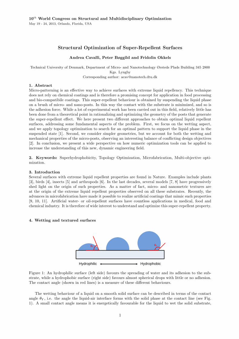
1. AbstractMicro-patterning is an effective way to achieve surfaces with extreme liquid repellency. This techniquedoes not rely on chemical coatings and is therefore a promising concept for application in food processingand bio-compatibile coatings. This super-repellent behaviour is obtained by suspending the liquid phaseon a brush of micro- and nano-posts. In this way the contact with the substrate is minimized, and so isthe adhesion force. While a lot of experimental work has been carried out in this field, relatively little hasbeen done from a theoretical point in rationalizing and optimizing the geometry of the posts that generatethe super-repellent effect. We here present two different approaches to obtain optimal liquid repellentsurfaces, addressing some fundamental aspects of the problem. First, we focus on the wetting aspect,and we apply topology optimization to search for an optimal pattern to support the liquid phase in thesuspended state [1]. Second, we consider simpler geometries, but we account for both the wetting andmechanical properties of the micro-posts, observing an interesting balance of conflicting design objectives[2]. In conclusion, we present a wide perspective on how numeric optimization tools can be applied toincrease the understanding of this new, dynamic engineering field.
2. Keywords: Superhydrophobicity, Topology Optimization, Microfabrication, Multi-objective opti-mization.
3. IntroductionSeveral surfaces with extreme liquid repellent properties are found in Nature. Examples include plants[3], birds [4], insects [5] and arthropods [6]. In the last decades, several models [7, 8] have progressivelyshed light on the origin of such properties. As a matter of fact, micro- and nanometric textures areat the origin of the extreme liquid repellent properties observed on all these substrates. Recently, theadvances in microfabrication have made it possible to realize artificial coatings that mimic such properties[9, 10, 11]. Artificial water- or oil-repellent surfaces have countless applications in medical, food andchemical industry. It is therefore of wide interest to understand and optimize this super-repellent property.
4. Wetting and textured surfaces
Hydrophilic Hydrophobic
θYθY
Figure 1: An hydrophilic surface (left side) favours the spreading of water and its adhesion to the sub-strate, while a hydrophobic surface (right side) favours almost spherical drops with little or no adhesion.The contact angle (shown in red lines) is a measure of these different behaviours.
The wetting behaviour of a liquid on a smooth solid surface can be described in terms of the contactangle θY , i.e. the angle the liquid-air interface forms with the solid phase at the contact line (see Fig.1). A small contact angle means it is energetically favourable for the liquid to wet the solid substrate,
1
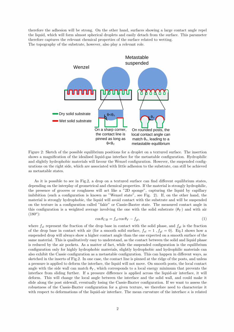
therefore the adhesion will be strong. On the other hand, surfaces showing a large contact angle repelthe liquid, which will form almost spherical droplets and easily detach from the surface. This parametertherefore captures the relevant chemical properties of the surface related to wetting.The topography of the substrate, however, also play a relevant role.
Metastable
suspended Wenzel
θY
Dry solid substrate
Wet solid substrate
θ<θY
On a sharp corner,
the contact line is
pinned as long as
θ<θY
On rounded posts, the
local contact angle can
match θY, leading to a
metastable equilibrium
Figure 2: Sketch of the possible equilibrium positions for a droplet on a textured surface. The insertionshows a magnification of the idealised liquid-gas interface for the metastable configuration. Hydrophilicand slightly hydrophobic materials will favour the Wenzel configuration. However, the suspended config-urations on the right side, which are associated with little adhesion to the substrate, can still be achievedas metastable states.
As it is possible to see in Fig.2, a drop on a textured surface can find different equilibrium states,depending on the interplay of geometrical and chemical properties. If the material is strongly hydrophilic,the presence of grooves or roughness will act like a ”2D sponge”, capturing the liquid by capillaryimbibition (such a configuration is known as ”Wenzel state”, see Fig. 2). If, on the other hand, thematerial is strongly hydrophobic, the liquid will avoid contact with the substrate and will be suspendedon the texture in a configuration called ”fakir” or Cassie-Baxter state. The measured contact angle inthis configuration is a weighted average involving the one with the solid substrate (θY ) and with air(180o):
cos θCB = fsl cos θY − fgl, (1)
where fsl represent the fraction of the drop base in contact with the solid phase, and fgl is the fractionof the drop base in contact with air (for a smooth solid surface, fsl = 1 , fgl = 0). Eq.1 shows how asuspended drop will always show a higher contact angle than the one expected on a smooth surface of thesame material. This is qualitatively easy to understand, as the contact between the solid and liquid phaseis reduced by the air pockets. As a matter of fact, while the suspended configuration is the equilibriumconfiguration only for highly hydrophobic materials, slightly hydrophobic and hydrophilic materials canalso exhibit the Cassie configuration as a metastable configuration. This can happen in different ways, assketched in the inserts of Fig.2. In one case, the contact line is pinned at the ridge of the posts, and unlessa pressure is applied to deform the interface, the liquid will not move. On smooth posts, the local contactangle with the side wall can match θY , which corresponds to a local energy minimum that prevents theinterface from sliding further. If a pressure difference is applied across the liquid-air interface, it willdeform. This will change the local angle between the interface and the solid wall, and could make itslide along the post sidewall, eventually losing the Cassie-Baxter configuration. If we want to assess therobustness of the Cassie-Baxter configuration for a given texture, we therefore need to characterize itwith respect to deformations of the liquid-air interface. The mean curvature of the interface κ is related
2
to the pressure difference ∆P across it through the Young-Laplace relation:
∆P = γκ, (2)
where γ is the surface tension of the fluid, i.e. the energy cost per unit area of an interface between liquidand gas phases. Without going into mathematical details, Eq. 2 tells a lot about how much pressure adrop in the Cassie state can support before the liquid wets the substrate. For example, we see that a highsurface tension γ means less interface deformation for the same applied pressure. Moreover, curvaturehas units of inverse length: this means that, the smaller the spacing in the texture, the harder it is topush the liquid among posts or grooves.
The concepts introduced in this section are all we need to understand the results presented in thefollowing. In section 5, we apply topology optimization to find an optimal post cross section, thatminimizes the interface deformation upon applied pressure, while keeping the solid fraction fsl (and thusthe apparent contact angle θCB) fixed. In section 6 we consider a similar problem (optimal supportwith limited surface covering), for overhanging structures, which are suitable for achieving the Cassie-Baxter state in hydrophilic materials. We therefore introduce the constraint of mechanical stability, whichbecomes relevant for the geometry we address.
5. Topology optimization of superhydrophobic surfaces
D D
γ(x)
B) C)
A)
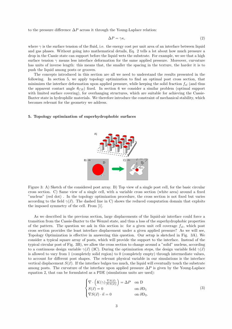
Figure 3: A) Sketch of the considered post array. B) Top view of a single post cell, for the basic circularcross section. C) Same view of a single cell, with a variable cross section (white area) around a fixed”nucleus” (red dot) . In the topology optimization procedure, the cross section is not fixed but variesaccording to the field γ(~x). The dashed line in C) shows the reduced computation domain that exploitsthe imposed symmetry of the cell. From [1].
As we described in the previous section, large displacements of the liquid-air interface could force atransition from the Cassie-Baxter to the Wenzel state, and thus a loss of the superhydrophobic propertiesof the pattern. The question we ask in this section is: for a given unit cell coverage fsl, which postcross section provides the least interface displacement under a given applied pressure? As we will see,Topology Optimization is effective in answering this question. Our setup is sketched in Fig. 3A). Weconsider a typical square array of posts, which will provide the support to the interface. Instead of thetypical circular post of Fig. 3B), we allow the cross section to change around a ”solid” nucleus, accordingto a continuous design variable γ(~x) (3C). During the optimization steps, the design variable field γ(~x)is allowed to vary from 1 (completely solid region) to 0 (completely empty) through intermediate values,to account for different post shapes. The relevant physical variable in our simulations is the interfacevertical displacement S(~x). If the interface bulges too much, the liquid will eventually touch the substrateamong posts. The curvature of the interface upon applied pressure ∆P is given by the Young-Laplaceequation 2, that can be formulated as a PDE (simulations units are used):
∇ ·(K(γ) ∇S(~x)
|∇S(~x)|
)= ∆P on D
S(~x) = 0 on ∂D1
∇S(~x) · ~n = 0 on ∂D2.
(3)
3
The boundary conditions on ∂D1 and ∂D2 account for the central support and the periodicity of the unitcell, respectively. Eqs. 3 depend on the design variable γ(~x) through the function K(γ) defined as:
K(γ) = 1 +(Kmax − 1) · q · γ
(q + 1− γ). (4)
This coupling was inspired by optimal heat conduction problems [12], and provides the desired interplaybetween the interface and the material distribution. Where γ(~x) = 0, K(γ) is equal to 1, and we recoverthe Young-Laplace equation in absence of material. If γ(~x) = 1, K(γ) is equal to Kmax (set to 105 inour simulations). This corresponds to a huge local increase in the surface tension of the interface, whichas a consequence will almost not deform, and we therefore get γ(~x) = 1→ S(~x) ' 0 as the ”solid phase”condition. The goal of the optimization procedure is to minimize the maximum interface deformation. Asuitable choice for our objective function Φ will then be the squared integral displacement of the interface∗
Φ =
∫D
S2(~x) dA. (5)
The specific coupling between γ(~x) and S(~x) we choose leads to connected binary solid/empty designs,as K(γ) ”radiates” the support from ∂D1 to the rest of the domain. We therefore do not allow the postto split into smaller isolated features. While the overall length scale of the texture is indeed a relevantparameter, we are here interested in the optimal shape of a single feature, which can then be scaled upor down according to the fabrication constraints.
At every optimization iteration, The Young-Laplace equation Eq. (2) is then solved to obtain S(~x).The objective function Φ and sensitivity δΦ
δγ(~x) are then computed, and used to update γ(~x). Details on
the sensitivity analysis and the implementation of the code can be found in the paper by Olesen et al. [14].Eq.2 shows that the displacement of the interface is reduced for small length scales. This suggest thathighly ramified design would probably be optimal, but difficult to fabricate on a micron or sub-micronlength. In order to impose a minimum length scale, our optimization involves also a filtering step on thedesign variable γ(~x). At every iteration in the optimisation routine we calculate a smoothed version γ(~x)of the design variable γ(~x), applying a PDE filter [15]:
L2diff∇2γ(~x) = γ(~x)− γ(~x). (6)
γ(~x) is the quantity actually used in the objective function and sensitivity analysis. This process allowsto control the minimum size of the features appearing in the optimal design and avoids optimal designsapproaching the mesh length scale. The relevant PDEs are solved using the commercial software COM-SOL, while the optimization relies on the method of moving asimptotes (MMA) [16].
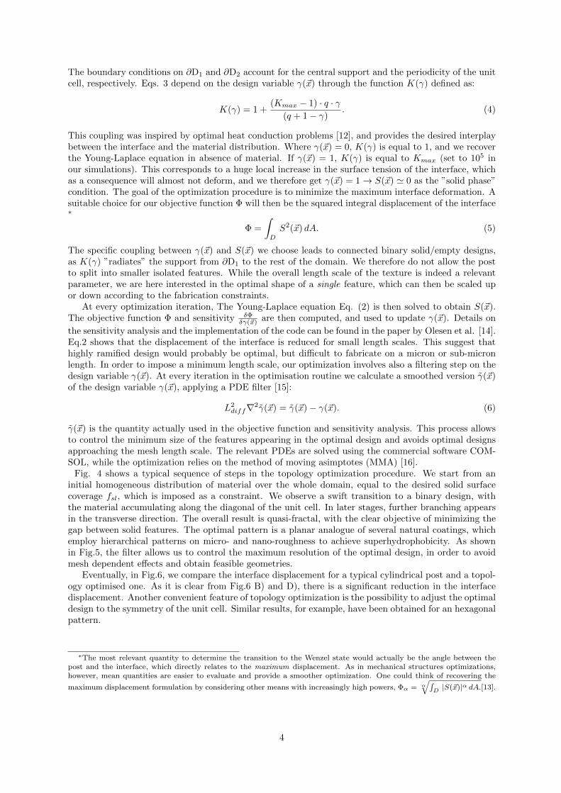
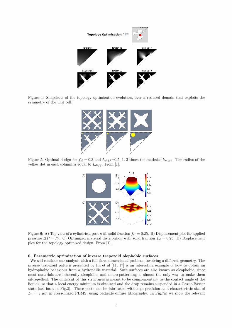
Fig. 4 shows a typical sequence of steps in the topology optimization procedure. We start from aninitial homogeneous distribution of material over the whole domain, equal to the desired solid surfacecoverage fsl, which is imposed as a constraint. We observe a swift transition to a binary design, withthe material accumulating along the diagonal of the unit cell. In later stages, further branching appearsin the transverse direction. The overall result is quasi-fractal, with the clear objective of minimizing thegap between solid features. The optimal pattern is a planar analogue of several natural coatings, whichemploy hierarchical patterns on micro- and nano-roughness to achieve superhydrophobicity. As shownin Fig.5, the filter allows us to control the maximum resolution of the optimal design, in order to avoidmesh dependent effects and obtain feasible geometries.
Eventually, in Fig.6, we compare the interface displacement for a typical cylindrical post and a topol-ogy optimised one. As it is clear from Fig.6 B) and D), there is a significant reduction in the interfacedisplacement. Another convenient feature of topology optimization is the possibility to adjust the optimaldesign to the symmetry of the unit cell. Similar results, for example, have been obtained for an hexagonalpattern.
∗The most relevant quantity to determine the transition to the Wenzel state would actually be the angle between thepost and the interface, which directly relates to the maximum displacement. As in mechanical structures optimizations,however, mean quantities are easier to evaluate and provide a smoother optimization. One could think of recovering the
maximum displacement formulation by considering other means with increasingly high powers, Φα = α√∫
D |S(~x)|α dA.[13].
4
Topology Optimisation,
Figure 4: Snapshots of the topology optimization evolution, over a reduced domain that exploits thesymmetry of the unit cell.
Figure 5: Optimal design for fsl = 0.3 and Ldiff=0.5, 1, 3 times the meshsize hmesh. The radius of theyellow dot in each column is equal to Ldiff . From [1].
A) B)
C) D)
Figure 6: A) Top view of a cylindrical post with solid fraction fsl = 0.25. B) Displacement plot for appliedpressure ∆P = P0. C) Optimized material distribution with solid fraction fsl = 0.25. D) Displacementplot for the topology optimized design. From [1].
6. Parametric optimization of inverse trapezoid olephobic surfacesWe will continue our analysis with a full three dimensional problem, involving a different geometry. The
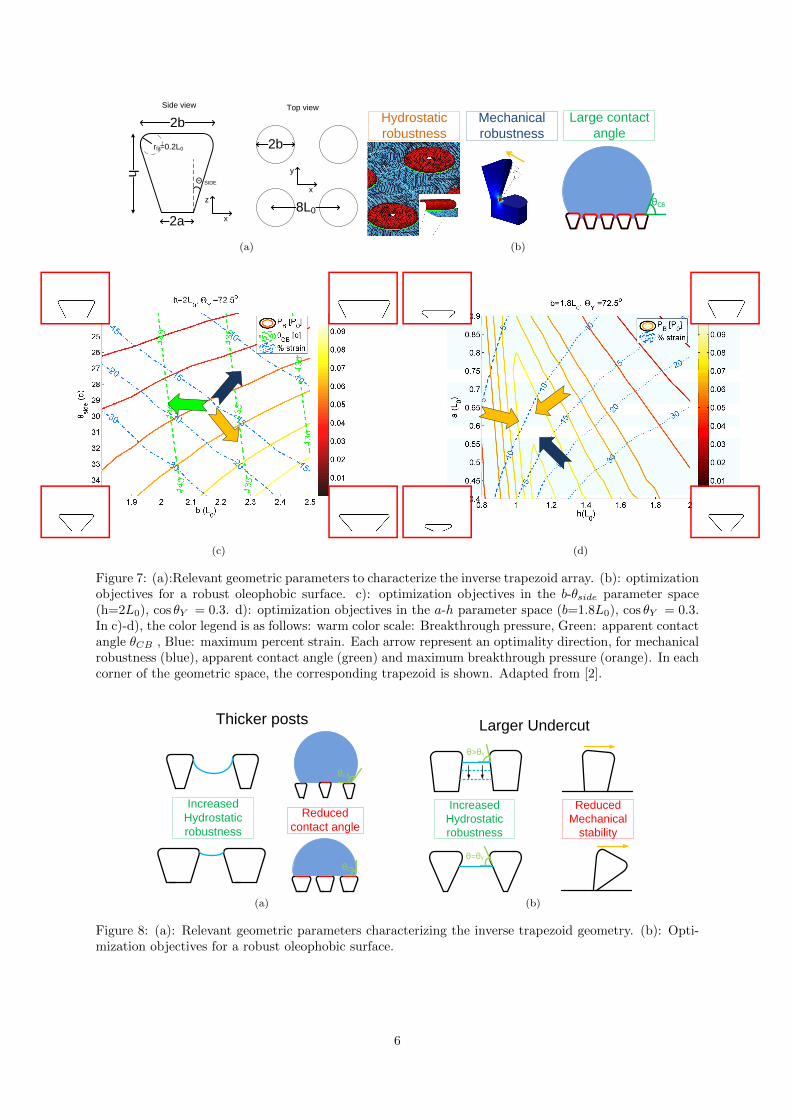
inverse trapezoid pattern presented by Im et al [11, 17] is an interesting example of how to obtain anhydrophobic behaviour from a hydrophilic material. Such surfaces are also known as oleophobic, sincemost materials are inherently oleophilic, and micro-patterning is almost the only way to make themoil-repellent. The undercut of this structures is meant to be complementary to the contact angle of theliquids, so that a local energy minimum is obtained and the drop remains suspended in a Cassie-Baxterstate (see inset in Fig.2). These posts can be fabricated with high precision at a characteristic size ofL0 = 5 µm in cross-linked PDMS, using backside diffuse lithography. In Fig.7a) we show the relevant
5
2a
2b
h
rfil=0.2L0 2b
8L0x
z
x
y
Side view Top view
Θ SIDE
(a)
θCB
Hydrostatic
robustness
Mechanical
robustness
Large contact
angle
(b)
(c) (d)
Figure 7: (a):Relevant geometric parameters to characterize the inverse trapezoid array. (b): optimizationobjectives for a robust oleophobic surface. c): optimization objectives in the b-θside parameter space(h=2L0), cos θY = 0.3. d): optimization objectives in the a-h parameter space (b=1.8L0), cos θY = 0.3.In c)-d), the color legend is as follows: warm color scale: Breakthrough pressure, Green: apparent contactangle θCB , Blue: maximum percent strain. Each arrow represent an optimality direction, for mechanicalrobustness (blue), apparent contact angle (green) and maximum breakthrough pressure (orange). In eachcorner of the geometric space, the corresponding trapezoid is shown. Adapted from [2].
Increased
Hydrostatic
robustness
Reduced
contact angle
θCB
θCB
Thicker posts
(a)
Increased
Hydrostatic
robustness
θ>θY
θ=θY
Reduced
Mechanical
stability
Larger Undercut
(b)
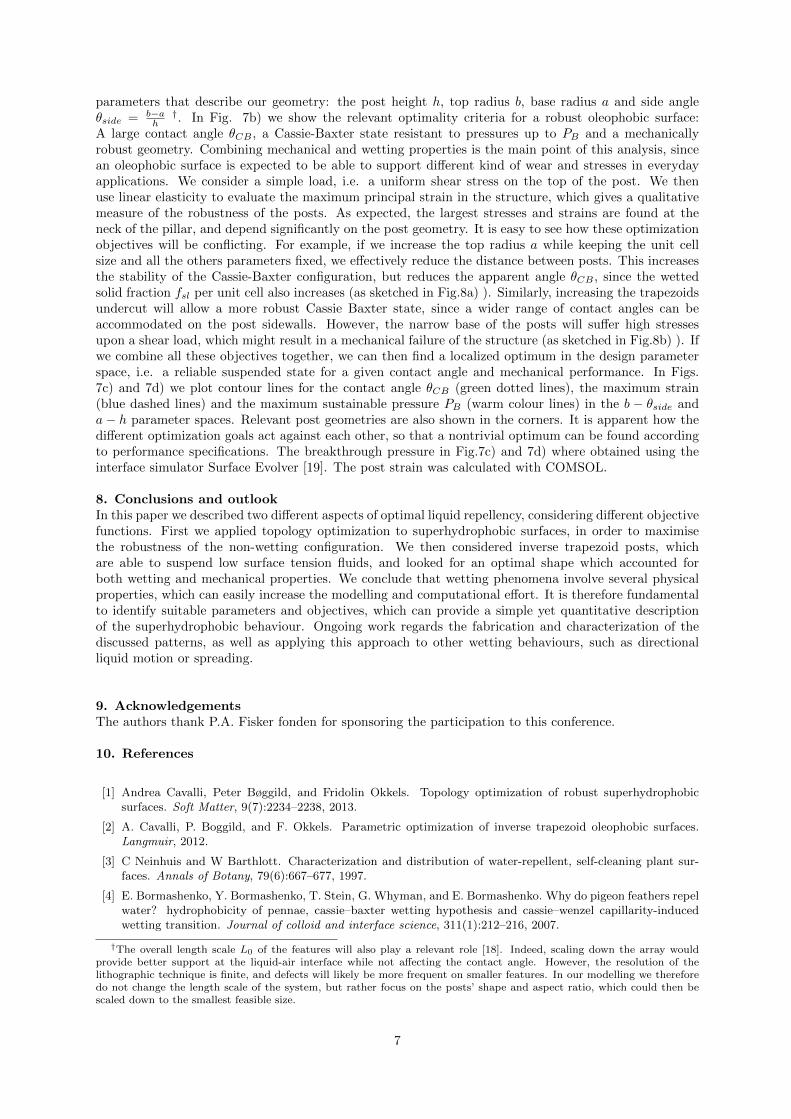
Figure 8: (a): Relevant geometric parameters characterizing the inverse trapezoid geometry. (b): Opti-mization objectives for a robust oleophobic surface.
6
parameters that describe our geometry: the post height h, top radius b, base radius a and side angleθside = b−a
h†. In Fig. 7b) we show the relevant optimality criteria for a robust oleophobic surface:
A large contact angle θCB , a Cassie-Baxter state resistant to pressures up to PB and a mechanicallyrobust geometry. Combining mechanical and wetting properties is the main point of this analysis, sincean oleophobic surface is expected to be able to support different kind of wear and stresses in everydayapplications. We consider a simple load, i.e. a uniform shear stress on the top of the post. We thenuse linear elasticity to evaluate the maximum principal strain in the structure, which gives a qualitativemeasure of the robustness of the posts. As expected, the largest stresses and strains are found at theneck of the pillar, and depend significantly on the post geometry. It is easy to see how these optimizationobjectives will be conflicting. For example, if we increase the top radius a while keeping the unit cellsize and all the others parameters fixed, we effectively reduce the distance between posts. This increasesthe stability of the Cassie-Baxter configuration, but reduces the apparent angle θCB , since the wettedsolid fraction fsl per unit cell also increases (as sketched in Fig.8a) ). Similarly, increasing the trapezoidsundercut will allow a more robust Cassie Baxter state, since a wider range of contact angles can beaccommodated on the post sidewalls. However, the narrow base of the posts will suffer high stressesupon a shear load, which might result in a mechanical failure of the structure (as sketched in Fig.8b) ). Ifwe combine all these objectives together, we can then find a localized optimum in the design parameterspace, i.e. a reliable suspended state for a given contact angle and mechanical performance. In Figs.7c) and 7d) we plot contour lines for the contact angle θCB (green dotted lines), the maximum strain(blue dashed lines) and the maximum sustainable pressure PB (warm colour lines) in the b − θside anda− h parameter spaces. Relevant post geometries are also shown in the corners. It is apparent how thedifferent optimization goals act against each other, so that a nontrivial optimum can be found accordingto performance specifications. The breakthrough pressure in Fig.7c) and 7d) where obtained using theinterface simulator Surface Evolver [19]. The post strain was calculated with COMSOL.
8. Conclusions and outlookIn this paper we described two different aspects of optimal liquid repellency, considering different objectivefunctions. First we applied topology optimization to superhydrophobic surfaces, in order to maximisethe robustness of the non-wetting configuration. We then considered inverse trapezoid posts, whichare able to suspend low surface tension fluids, and looked for an optimal shape which accounted forboth wetting and mechanical properties. We conclude that wetting phenomena involve several physicalproperties, which can easily increase the modelling and computational effort. It is therefore fundamentalto identify suitable parameters and objectives, which can provide a simple yet quantitative descriptionof the superhydrophobic behaviour. Ongoing work regards the fabrication and characterization of thediscussed patterns, as well as applying this approach to other wetting behaviours, such as directionalliquid motion or spreading.
9. AcknowledgementsThe authors thank P.A. Fisker fonden for sponsoring the participation to this conference.
10. References
[1] Andrea Cavalli, Peter Bøggild, and Fridolin Okkels. Topology optimization of robust superhydrophobicsurfaces. Soft Matter, 9(7):2234–2238, 2013.
[2] A. Cavalli, P. Boggild, and F. Okkels. Parametric optimization of inverse trapezoid oleophobic surfaces.Langmuir, 2012.
[3] C Neinhuis and W Barthlott. Characterization and distribution of water-repellent, self-cleaning plant sur-faces. Annals of Botany, 79(6):667–677, 1997.
[4] E. Bormashenko, Y. Bormashenko, T. Stein, G. Whyman, and E. Bormashenko. Why do pigeon feathers repelwater? hydrophobicity of pennae, cassie–baxter wetting hypothesis and cassie–wenzel capillarity-inducedwetting transition. Journal of colloid and interface science, 311(1):212–216, 2007.
†The overall length scale L0 of the features will also play a relevant role [18]. Indeed, scaling down the array wouldprovide better support at the liquid-air interface while not affecting the contact angle. However, the resolution of thelithographic technique is finite, and defects will likely be more frequent on smaller features. In our modelling we thereforedo not change the length scale of the system, but rather focus on the posts’ shape and aspect ratio, which could then bescaled down to the smallest feasible size.
7
[5] Xuefeng Gao and Lei Jiang. Biophysics: water-repellent legs of water striders. Nature, 432(7013):36–36,2004.
[6] Ralf Helbig, Julia Nickerl, Christoph Neinhuis, and Carsten Werner. Smart skin patterns protect springtails.PloS one, 6(9):e25105, 2011.
[7] Robert N Wenzel. Resistance of solid surfaces to wetting by water. Ind. Eng. Chem, 28(8):988–994, 1936.
[8] A. B. D. Cassie and S. Baxter. Wettability of porous surfaces. Trans. Faraday Soc., 40(0):546–551, 1944.
[9] A. Tuteja, W. Choi, J. M. Mabry, G. H. McKinley, and R. E. Cohen. Robust omniphobic surfaces. Proceedingsof the National Academy of Sciences, 105(47):18200, 2008.
[10] J. Bico, C. Marzolin, and D. Quere. Pearl drops. EPL (Europhysics Letters), 47:220, 1999.
[11] Maesoon Im, Hown Im, Joo-Hyung Lee, Jun-Bo Yoon, and Yang-Kyu Choi. A robust superhydrophobic andsuperoleophobic surface with inverse-trapezoidal microstructures on a large transparent flexible substrate.Soft Matter, 6(7):1401–1404, 2010.
[12] A. Gersborg-Hansen, M. P. Bendsøe, and O. Sigmund. Topology optimization of heat conduction problemsusing the finite volume method. Structural and multidisciplinary optimization, 31(4):251–259, 2006.
[13] M. P. Bendsøe and O. Sigmund. Topology optimization: theory, methods, and applications. Springer Verlag,2003.
[14] L. H. Olesen, F. Okkels, and H. Bruus. A high-level programming-language implementation of topologyoptimization applied to steady-state navier–stokes flow. International Journal for Numerical Methods inEngineering, 65(7):975–1001, 2006.
[15] B. S. Lazarov and O. Sigmund. Filters in topology optimization based on helmholtz-type differential equa-tions. International Journal for Numerical Methods in Engineering, 86(6):765–781, 2011.
[16] K. Svanberg. The method of moving asymptotes: a new method for structural optimization. Internationaljournal for numerical methods in engineering, 24(2):359–373, 1987.
[17] Maesoon Im, Hwon Im, Joo-Hyung Lee, Jun-Bo Yoon, Yang-Kyu Choi, et al. Analytical modeling and ther-modynamic analysis of robust superhydrophobic surfaces with inverse-trapezoidal microstructures. Langmuir,26(22):17389, 2010.
[18] Shreerang S Chhatre, Wonjae Choi, Anish Tuteja, Kyoo-Chul Park, Joseph M Mabry, Gareth H McKinley,and Robert E Cohen. Scale dependence of omniphobic mesh surfaces. Langmuir, 26(6):4027–4035, 2009.
[19] Kenneth A Brakke. The surface evolver. Experimental mathematics, 1(2):141–165, 1992.
8