Embed Size (px)
Citation preview
151
STRUCTURAL OPTIMIZATION OF SPACE SYSTEMS USING GENETIC ALGORITHMS
John G. Furumo
College of Engineering University of Hawai‘i at Mānoa
Honolulu, HI 96822
The common engineering practice of design followed by analysis, while effective, is far from nominal due to its iterative nature. While it is practically impossible to remove all iteration from the design process due to the high stakes involved and demanding design requirements, design optimization can greatly streamline the process. Cutting-edge optimization software such as Altair’s Optistruct and NASA’s X-TOOLSS use gradient-based algorithms and genetic algorithms, respectively, to produce optimal designs satisfying specified requirements. The application of these tools to structural optimization of satellite payloads is an important proof-of-concept study that will guide future payload and space system development. My research has sought to apply the optimization process in parallel with the conventional design process that is currently underway developing the next generation of FASTSAT microsatellites. Decades of flight heritage have conveyed well-suited structural member configurations such as ortho-grid and iso-grid panels that maximize strength and stiffness while minimizing mass. The optimization process driven by Optistruct demonstrated a new and unconventional structural layout that saved mass and volume over the original FASTSAT-HSV02 design while maintaining structural strength and integrity. Future X-TOOLSS optimization can further enhance the process, yielding global optimum configurations for satellite structures.
NOMENCLATURE
CAD = computer-aided design FEA = finite element analysis X-TOOLSS = eXploration Toolset for Optimization Of Launch and Space Systems MSFC = Marshall Space Flight Center FASTSAT = Fast, Affordable, Science and Technology SATellite SLS = Space Launch System LEO = low earth orbit LV = launch vehicle ESPA = EELV Secondary Payload Adapter
INTRODUCTION
The preliminary stage of aerospace vehicle and systems development is usually divided between design and analysis phases. This was true for past generations of engineers relying on drafting and hand calculations as well as modern engineers utilizing computer-based CAD and FEA tools to fulfill the same purposes of design and analysis. For large-scale and complex projects, the design and analysis process generally becomes highly iterative in nature. In such cases, designs must be verified by analysis after each revision. While tedious and time-
152
consuming, this method has proven to be highly effective. Even the most highly coordinated efforts, however, still suffer from delays and setbacks due to this design-analysis iteration.
Design optimization is a new process that serves to effectively combine the design and analysis phases, achieving goals of both in a single step. Cutting-edge software tools such as Optistruct, part of Altair’s HyperWorks suite, and NASA’s X-TOOLSS allow designers to perform elements of CAD and FEA simultaneously. Such tools yield designs or guidelines to design that meet specified design requirements from the start, thereby eliminating the need for analysis afterward to verify the design. While design optimization has great potential, it is difficult to apply to complex designs as the large quantity of degrees of freedom involved makes it difficult or impossible to find a single optimum configuration. As a result, optimization tools are usually focused on small scale or component-level studies.
RESEARCH PURPOSE
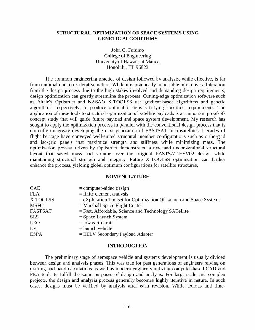
The ES22 Thermal & Mechanical Analysis Branch has an interest in optimization as it relates to their common duties of verifying space system design iterations. With the cancellation of the Ares program and the delays in the start of the SLS program, ES22 has been focused more on payload instead of vehicle systems. One example of a payload that that ES22 has worked on recently is the FASTSAT microsatellite that was designed and fabricated at MSFC. FASTSAT provides a cheap and accessible platform for scientific instruments as part of NASA’s new focus on reducing mission costs and development time by creating smaller and cheaper payloads for LEO. The first generation, FASTSAT-HSV01, was launched last year and has performed so well that a second generation, FASTSAT-HSV02, is now on the drawing board. Figure 1 shows FASTSAT-HSV01 in the clean room prior to launch. Design group ES21 is currently finalizing the FASTSAT-HSV02 design while ES22 is providing design verification through structural and thermal analysis. Figure 2 below shows the current iteration of the FASTSAT-HSV02 CAD model created by ES21.
153
Figure 1: FASTSAT-HSV01 [1]
Figure 2: FASTSAT-HSV02 CAD model
154
My research sought to apply the optimization process in parallel with this conventional development process now being carried out by ES21 in concert with ES22 as a proof-of-concept and guide for future design optimization. In particular, my objective was to optimize the structural design of the satellite, with the goals of minimizing structural mass while maintaining structural strength and stiffness. This was performed by a previous ES22 intern for FASTSAT-HSV01 [2], demonstrating the capability of the optimization toolset. The hope of my mentor was that I would be able to replicate the process and document it so that it could be applied to future projects from the start.
METHODOLOGY
The first step of the structural optimization process was performed using the aforementioned Optistruct solver from Altair Engineering. Optistruct utilizes gradient-based optimization methods to converge on a design satisfying given requirements. These studies are performed on FEA models which contain important information that define the simulation. These include boundary conditions such as constraints and loading conditions. For the case of the FASTSAT-HSV02 FEA model, the loading condition considered was a lateral 15 G static acceleration representing the launch loads. The dynamic conditions of the launch environment can be encapsulated by a single static acceleration [3]. As a microsatellite-class payload, FASTSAT mates to the LV via an ESPA ring payload adapter as a secondary payload which is mounted laterally with relation to the rocket’s direction of travel, hence the direction of the loading condition simulated [4]. The LV interface ring serves as the constraints for the model, the points which remain fixed and unable to move.
For these optimization studies, there are several parameters that must be defined by the user. The first of these is a design objective. This is the overarching goal that the solver seeks to achieve through the simulation. For the purpose of the structural optimization of FASTSAT-HSV02, the design objective was to minimize mass, minimize volume, or minimize compliance. Because the only design material considered was 7075-T6 Aluminum, an isotropic material, mass and volume would be minimized simultaneously. Compliance is the inverse of stiffness, and so minimizing it would maximize the stiffness of the overall structure. One of the drawbacks of Optistruct is that only one design objective can be sought at a time.
Another user-specified property of the optimization study is the design variable. This is the property of the model that Optistruct varies in order to meet the design objective. For structural optimization, the design variable depends on the type of optimization being performed. For this project, both a topology optimization and a gauge optimization study were performed.
TOPOLOGY OPTIMIZATION
A useful first iteration of structural design optimization is a topology optimization. This is used with a 3-D FEA model comprised of solid elements. Topology will show load-paths through a structure and indicate areas of greatest stress. The design variable for a topology study is element density. In order to satisfy the design objective, the solver will vary the density of the model elements. Topology is useful because it will reveal where extra structural material is needed in order to shore up the structure, and vice-versa where material can be shaved off to
155
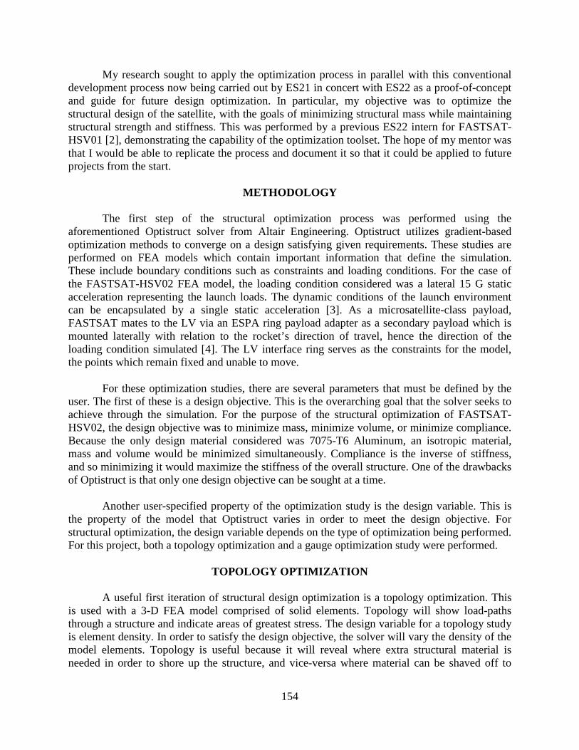
lighten the structure. Figure 3 below shows the FEA model I created for topology optimization using Pro-E and HyperMesh. The only components meshed for FEA and optimization are the structural members. The internal components have been modeled as point masses connected to the structural elements via rigid bodies.
Figure 3: Topology model of FASTSAT-HSV02
I created this model by taking the structural components of the CAD model in figure 2 and wrapping the members in a solid design envelope. This provided the design space for Optistruct to work with to create the optimum pattern of material density.
GAUGE OPTIMIZATION
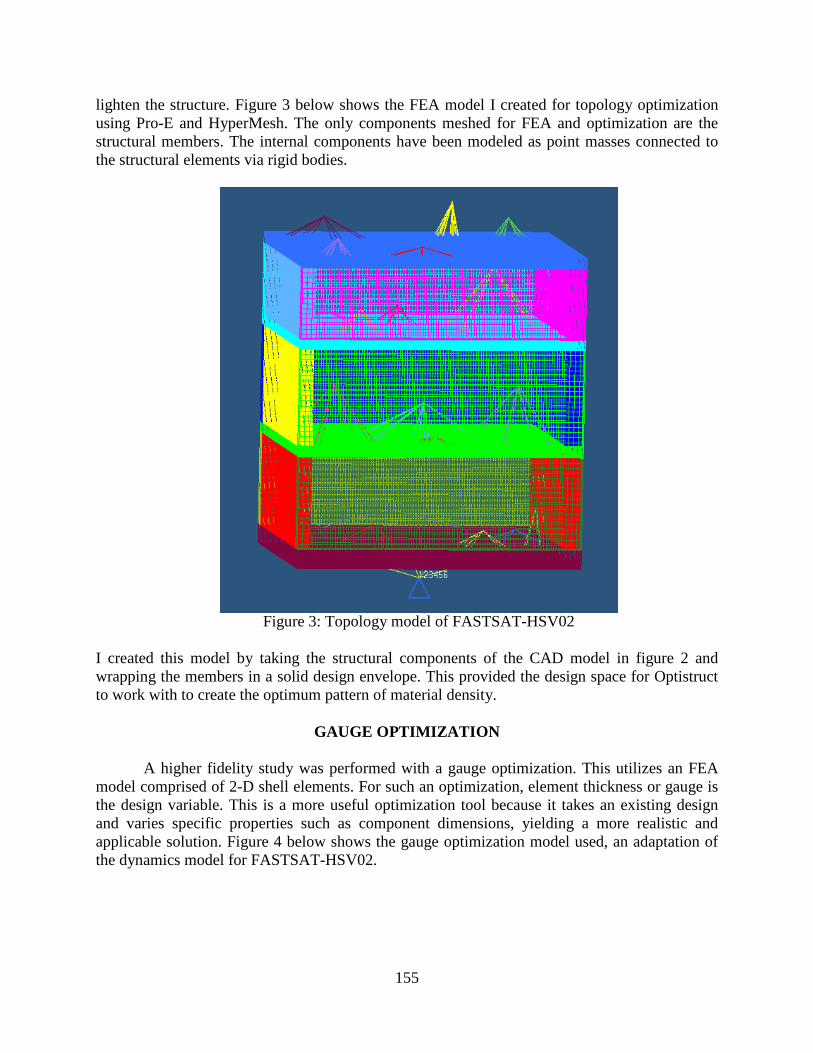
A higher fidelity study was performed with a gauge optimization. This utilizes an FEA model comprised of 2-D shell elements. For such an optimization, element thickness or gauge is the design variable. This is a more useful optimization tool because it takes an existing design and varies specific properties such as component dimensions, yielding a more realistic and applicable solution. Figure 4 below shows the gauge optimization model used, an adaptation of the dynamics model for FASTSAT-HSV02.
156
Figure 4: Gauge optimization model of FASTSAT-HSV02
Once again only the structural members are meshed for analysis, and the internal
components are modeled as point masses. As can be seen in figure 4, the structural elements are comprised of 2-D shell elements instead of the 3-D solid elements used for the topology model seen in figure 3.
X-TOOLSS
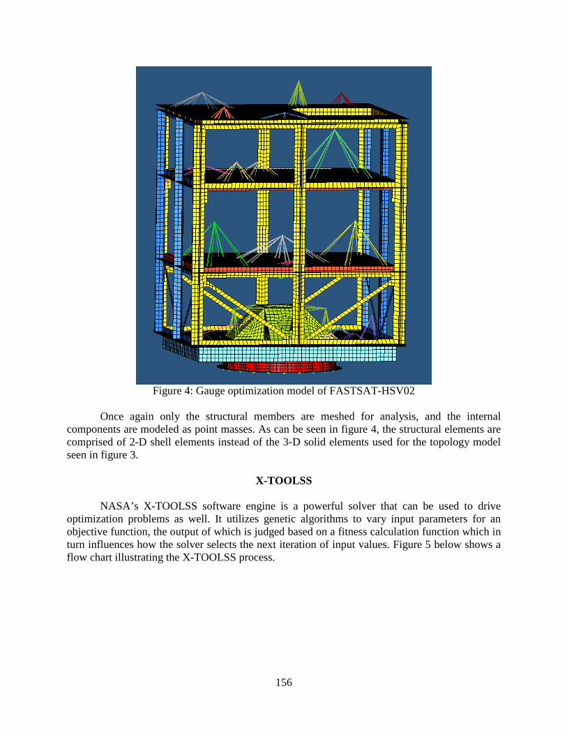
NASA’s X-TOOLSS software engine is a powerful solver that can be used to drive optimization problems as well. It utilizes genetic algorithms to vary input parameters for an objective function, the output of which is judged based on a fitness calculation function which in turn influences how the solver selects the next iteration of input values. Figure 5 below shows a flow chart illustrating the X-TOOLSS process.
157
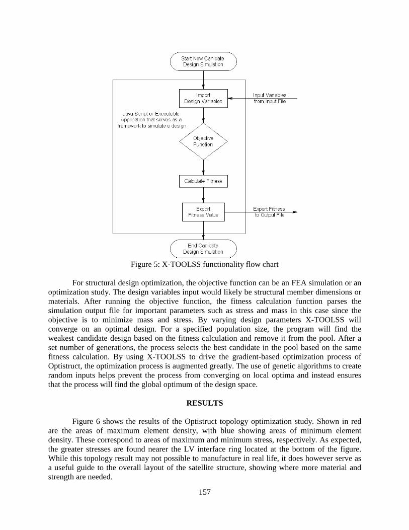
Figure 5: X-TOOLSS functionality flow chart
For structural design optimization, the objective function can be an FEA simulation or an
optimization study. The design variables input would likely be structural member dimensions or materials. After running the objective function, the fitness calculation function parses the simulation output file for important parameters such as stress and mass in this case since the objective is to minimize mass and stress. By varying design parameters X-TOOLSS will converge on an optimal design. For a specified population size, the program will find the weakest candidate design based on the fitness calculation and remove it from the pool. After a set number of generations, the process selects the best candidate in the pool based on the same fitness calculation. By using X-TOOLSS to drive the gradient-based optimization process of Optistruct, the optimization process is augmented greatly. The use of genetic algorithms to create random inputs helps prevent the process from converging on local optima and instead ensures that the process will find the global optimum of the design space.
RESULTS
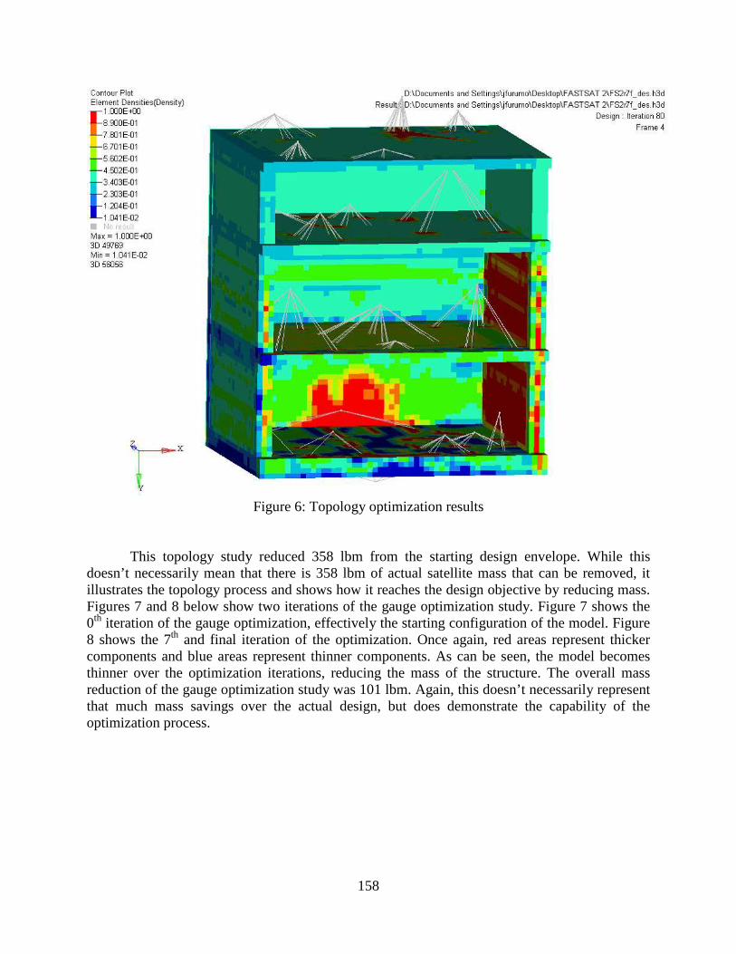
Figure 6 shows the results of the Optistruct topology optimization study. Shown in red are the areas of maximum element density, with blue showing areas of minimum element density. These correspond to areas of maximum and minimum stress, respectively. As expected, the greater stresses are found nearer the LV interface ring located at the bottom of the figure. While this topology result may not possible to manufacture in real life, it does however serve as a useful guide to the overall layout of the satellite structure, showing where more material and strength are needed.
158
Figure 6: Topology optimization results
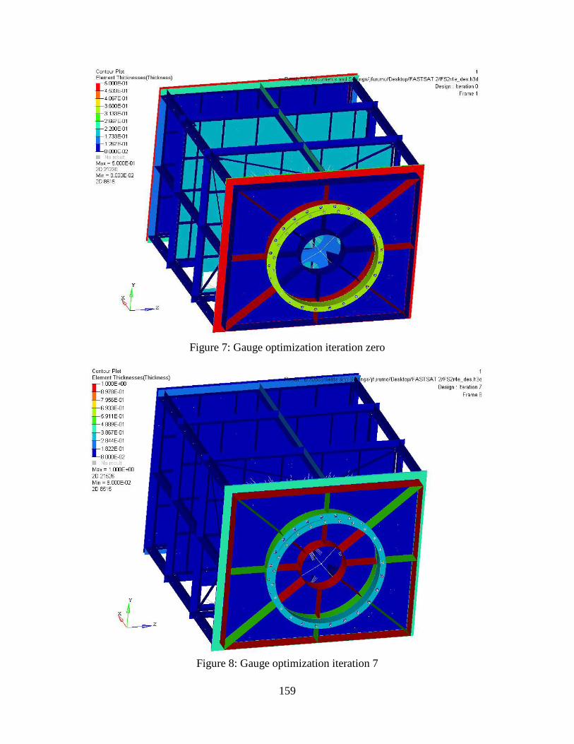
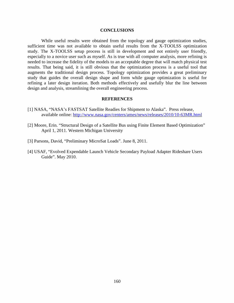
This topology study reduced 358 lbm from the starting design envelope. While this doesn’t necessarily mean that there is 358 lbm of actual satellite mass that can be removed, it illustrates the topology process and shows how it reaches the design objective by reducing mass. Figures 7 and 8 below show two iterations of the gauge optimization study. Figure 7 shows the 0th iteration of the gauge optimization, effectively the starting configuration of the model. Figure 8 shows the 7th and final iteration of the optimization. Once again, red areas represent thicker components and blue areas represent thinner components. As can be seen, the model becomes thinner over the optimization iterations, reducing the mass of the structure. The overall mass reduction of the gauge optimization study was 101 lbm. Again, this doesn’t necessarily represent that much mass savings over the actual design, but does demonstrate the capability of the optimization process.
159
Figure 7: Gauge optimization iteration zero
Figure 8: Gauge optimization iteration 7
160
CONCLUSIONS
While useful results were obtained from the topology and gauge optimization studies, sufficient time was not available to obtain useful results from the X-TOOLSS optimization study. The X-TOOLSS setup process is still in development and not entirely user friendly, especially to a novice user such as myself. As is true with all computer analysis, more refining is needed to increase the fidelity of the models to an acceptable degree that will match physical test results. That being said, it is still obvious that the optimization process is a useful tool that augments the traditional design process. Topology optimization provides a great preliminary study that guides the overall design shape and form while gauge optimization is useful for refining a later design iteration. Both methods effectively and usefully blur the line between design and analysis, streamlining the overall engineering process.
REFERENCES [1] NASA, “NASA’s FASTSAT Satellite Readies for Shipment to Alaska”. Press release,
available online: http://www.nasa.gov/centers/ames/news/releases/2010/10-63MR.html [2] Moore, Erin. “Structural Design of a Satellite Bus using Finite Element Based Optimization”
April 1, 2011. Western Michigan University [3] Parsons, David, “Preliminary MicroSat Loads”. June 8, 2011. [4] USAF, “Evolved Expendable Launch Vehicle Secondary Payload Adapter Rideshare Users
Guide”. May 2010.