Embed Size (px)
Citation preview

NASA Technical Memorandum 104059
/' /_[ " t"
• ¢ , ,?
Structural Integrity of Wind TunnelWooden Fan Blades
Clarence P. Young, Jr., Robert T. Wingate, Kenneth W. Mort,James R. Rocker, and Harold E. Zager
April 1991
.....A._>A-T_'_-t04059) oT,_UCTJi-_,AL INTEGR'tTY !3F1 ,_t_:::L _°_OOi)_. _ _'-_:,,:, -AA _SLADES (NASA) 75 p
.._L 20_(
U n c I _ s
O0104.32
National Aeronautics andSpace Administration
Langley Research CenterHampton, Virginia 23665-5225
https://ntrs.nasa.gov/search.jsp?R=19910013276 2018-07-03T14:52:59+00:00Z


Foreword
This report was compiled by the NASA Inter-Center Committee on Structural
Integrity of Wooden Fan Blades. The authors are listed below along with their former
and/or present affiliation.
Dr. Clarence P. Young, Jr.
Formerly Assistant for Technology Development
Systems Engineering Division
NASA Langley Research Center
Presently: Visiting Associate Professor
North Carolina State University
Dr. Robert T. Wingate
Deputy Director, Systems Engineering and
Operations Directorate
NASA Langley Research Center
Mr. Kenneth W. Mort
Assistant Chief, Systems Engineering DivisionNASA Ames Research Center
Dr. James R. Rooker
Head, Structural Design Branch
Facilities Engineering Division
NASA Langley Research Center
Mr. Harold E. Zager (Now Retired)
Formerly 8 x 6/9 by 15/IRT Manager
Facilities Management Branch
Aeropropulsion Facilities and Experiment DivisionNASA Lewis Research Center
The committee wishes to recognize contributions by Dr. James W. Ramsey and
Mr_ _eter Lewis, NASA Langley Research Center, and Dr. Howard G. Nelson of the NASA
Ames Research Center.

•i_•k
TABLE OF CONTENTS
SUMMARY ........................................................................ i -
INTRODUCTION ................................................................... I
DESCRIPTION OF NASA WIND TUNNELS WITH WOODEN BLADES ............................ i
Ames Research Center Wind Tunnels Using Wooden Blades ........................ 2
Langley Research Center Tunnels Using Wooden Blades .......................... 4
Lewis Research Center Icing Research Tunnel .................................. 7
HISTORY OF WOODEN BLADE FAILURES ............................................... 7 _
Failure Modes ................................................................ 7
Spare Blade Requirements ..................................................... 8
RISK ASSESSMENT AND PROBABILITY OF FAILURE DUE TO DESIGN PROBLEMS FOR
EXISTING NASA WIND TUNNELS WITH WOODEN BLADES ................................
STATE OF THE ART FOR WOODEN FAN BLADE DESIGN ................................... i0
Materials Data Base .......................................................... i0
Failure Theories ............................................................. ii
Allowable Stress ............................................................. 12
Safe-Life Design (Fatigue and Fracture) ...................................... 12
Environmental Effects and Experience at NASA Centers ......................... 14
Design Loads ................................................................. 15
Ease of Maintenance and Inspection ........................................... 17
Frangible Tips and Tip Clearance ............................................. 17
Foreign Object Damage/Protection ............................................. 18
Proof/Component Testing ................................................. :.... 18
Hub Attachment ..................................... .......................... 19
Analytical Techniques for Stress Prediction ................................... 20
Rake and Sweep ................................................................ 21
Root/Hub Fairings ............................................................ 21
Fabrication .................................................................. 22
DRIVE SYSTEM DESIGN CONSIDERATIONS ............................................. 22
Balancing .................................................................... 22
Loss of 1/2 of the Blades .................................................... 22
Containment Shield ........................................................... 23
Interference (Campbell) Diagram .............................................. 23
Hub Region Venting ........................................................... 23
INSPECTION, MONITORING, AND REPAIR ............................................. 23
Written Procedures ........................................................... 24
Inspection Personnel ........ i ................................................ 24
Inspection Intervals .......................................................... 24
Inspection Methods ........................................................... 24
Vibration Testing as a Technique for Verifying/Evaluating
Blade Structural Integrity ................................................. 25
Fan Blade Repair ............................................................. 26
OUTLOOK FOR FUTURE USE OF WOOD IN FAN BLADE DESIGN ............................. 27
NASA WIND TUNNELS BLADE REPLACEMENTS ........................................... 28
iii
pRE_;ED_G PAGE BLANI( NOT F_L,_

TECHNOLOGY ASSESSMENT AND PROPOSED RESEARCH AND DEVELOPMENT ....................
Materials Research ...........................................................
Nondestructive Examination ...................................................
Monitoring Structural Integrity .................. ............................
CONCLUSIONS AND RECOMMENDATIONS ................................................
REFERENCES .....................................................................
APPENDIX A - SPARE PROPELLER BLADE SURVEY ......................................
28
28
29
30
3O
32
35
iv

Table
I
II
IIA
III
IV
V
Figure
i
2
3
4
5
6
7
8"
9
I0
ii
12
13
14
15
LIST OF TABLES AND FIGURES
Title
Description of NASA Wind Tunnels Wooden Fan Blades.
Probability of Failure Assessment Worksheet for NASA Wooden Fan Blade
Systems.
Probability of Failure Assessment Worksheet.
Mechanical Properties of Sitka Spruce and Hydulignum.
Allowable Stress for Sitka Spruce as Developed for the LaRC 16 Ft Tunnel
Blades.
Design Load Cases.
Title
NASA Ames Research Center 7- by 10-Foot Subsonic Wind Tunnel.
NASA Ames Research Center 40- by 80-/80- by 120-Foot Subsonic Wind Tunnel.
NASA Langley Research Center 7- by 10-Foot High Speed Tunnel.
NASA Langley Research Center 20-Ft Vertical Spin Wind Tunnel.
NASA Langley Research Center 12 Foot Low-Speed Tunnel.
NASA Langley Research Center 30- x 60-Foot Wind Tunnel.
NASA Langley Research Center 14- by 22-Foot Subsonic Tunnel.
NASA Langley Research Center 16-Foot Transonic Wind Tunnel.
NASA Lewis Research Center Icing Research Tunnel.
Hazard probability definitions and numerical ranges assigned for use withtable II.
NASA Langley Research Center Wind Tunnel Fan Blades Illustrating HubAttachment Geometries.
Hub attachment geometries illustrating shear out failure modes for
different bolt hole patterns.
Finite Element Models of the Transition Regions for the NASA Langley
Research Center. 7- by 10-Foot High Speed Wind Tunnel Fan.
Shear strength of laminated Sitka Spruce as a function of temperature.
Fatigue strength of laminated Sitka Spruces and Douglas Fir.
V
16
17
18
19
20
21
22
23
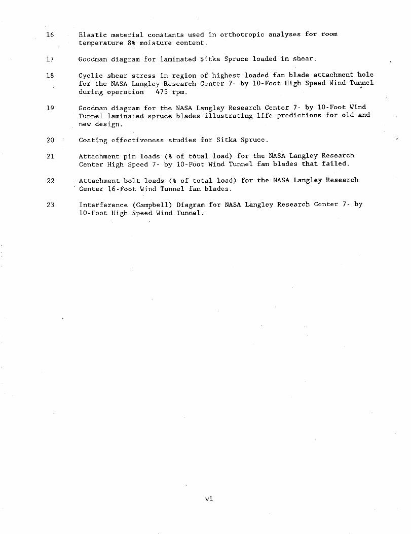
Elastic material constants used in orthotropic analyses for room
temperature 8% moisture content.
Goodman diagram for laminated Sitka Spruce loaded in shear.
Cyclic shear stress in region of highest loaded fan blade attachment hole
for the NASA Langley Research Center 7- by 10-Foot High Speed Wind Tunnel
during operation 475 rpm.
Goodman diagram for the NASA Langley Research Center 7- by 10-Foot Wind
Tunnel laminated spruce blades illustrating life predictions for old and
new design.
Coating effectiveness studies for Sitka Spruce.
Attachment pin loads (9 of total load) for the NASA Langley Research
Center High Speed 7- by 10-Foot Wind Tunnel fan blades that failed.
Attachment bolt loads (9 of total load) for the NASA Langley Research
Center 16-Foot Wind Tunnel fan blades.
Interference (Campbell) Diagram for NASA Langley Research Center 7- by
10-Foot High Speed Wind Tunnel.
vi

SUMMARY
This report presents information compiled by the NASA Inter-Center Committee on
Structural Integrity of Wooden Fan Blades and is intended for use as a guide in de-
sign, fabrication, evaluation, and assurance of fan systems using wooden blades. A
risk assessment approach for existing NASA wind tunnels with wooden fan blades is
provided. Also, state-of-the-art information is provided for wooden fan blade de-
sign, drive system considerations, inspection and monitoring methods, and fan blade
repair. Proposed research and development activities are discussed, and recommenda-
tions are provided which are aimed at future wooden fan blade design activities and
safely maintaining existing NASA wind-tunnel fan blades. This report contains infor-
mation that will be of value to wooden fan blade designers, fabricators, inspectors, !and wind-tunnel operations personnel.
INTRODUCTION
As a result of the catastrophic failure of the wooden fan blades in the NASA
Langley Research Centers' 7- by lO-Ft High Speed Wind Tunnel on July 9, 1985, an
inter-center committee was formed to study the potential implications for other NASAwind tunnels.
The charter of the committee was to develop methodology for evaluating and as-
suring the structural integrity of NASA wind-tunnel fan systems using wooden blades.
Areas of investigation were to include design criteria/philosophy; fabrication crite-
ria; analysis techniques; non-destructive examination methods and associated test
equipment; frequency and type of in-service inspection and evaluation; repair meth-
ods; life evaluation; in-service monitoring instrumentation; and environmentaleffects.
This report documents the findings and recommendations of the Committee. The
compilation of information on structural integrity of wooden fan blades is believed
to be unique and without precedent with application to wind tunnel fan systems uti-
lizing wooden blades.
DESCRIPTION OF NASA WIND TUNNELS WITH WOODEN FAN BLADES
At present there are ten NASA wind tunnels with wooden fan blades. These are asfollows:
Ames Research Center (ARC)
i. 7- x 10-Foot Wind Tunnel No. i
2. 7- x 10-Foot Wind Tunnel No. 2
3. 40- by 80-/80- by 120-Foot Wind Tunnel
Langley Research Center (LaRC)
4. 20-Foot Vertical Spin Wind Tunnel
5. 12-Foot Low Speed Wind Tunnel
6. 14- × 22-Foot Subsonic Wind Tunnel
7. 30- × 60-Foot Wind Tunnel
8. 7- x 10-Foot High Speed Tunnel9. 16-Foot Transonic Wind Tunnel
Lewis Research Center (LeRC)
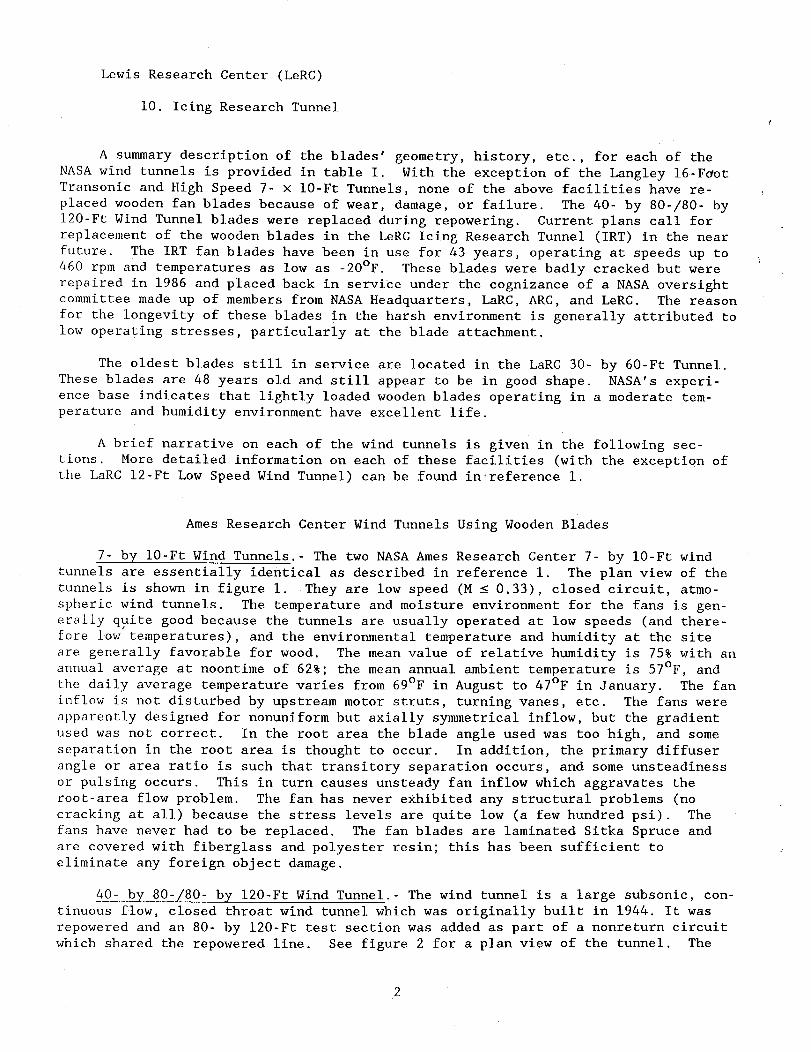
I0. Icing Research Tunnel
A summarydescription of the blades' geometry, history, etc., for each of theNASAwind tunnels is provided in table I. With the exception of the Langley 16-F_otTransonic and High Speed 7- x 10-Ft Tunnels, none of the above facilities have re-placed woodenfan blades because of wear, damage,or failure. The 40- by 80-/80- by120-Ft Wind Tunnel blades were replaced during repowering. Current plans call forreplacement of the woodenblades in the LeRCIcing Research Tunnel (IRT) in the nearfuture. The IRT fan blades have been in use for 43 years, operating at speeds up to460 rpm and temperatures as low as -20°F. These blades were badly cracked but wererepaired in 1986 and placed back in service under the cognizance of a NASAoversightcommittee madeup of membersfrom NASAHeadquarters, LaRC, ARC,and LeRC. The reasonfor the longevity of these blades in the harsh environment is generally attributed tolow operating stresses, particularly at the blade attachment.
The oldest blades still in service are located in the LaRC30- by 60-Ft Tunnel.Theseblades are 48 years old and still appear to be in good shape. NASA's experi-ence base indicates that lightly loaded woodenblades operating in a moderate tem-perature and humidity environment have excellent life.
A brief narrative on each of the wind tunnels is given in the following sec-tions. More detailed information on each of these facilities (with the exception ofthe LaRC12-Ft Low SpeedWind Tunnel) can be found in,reference I.
AmesResearch Center Wind Tunnels Using WoodenBlades
7- by 10-Ft Wind Tunnels.- The two NASA Ames Research Center 7- by 10-Ft wind
tunnels are essentially identical as described in reference i. The plan view of the
tunnels is shown in figure I. They are low speed (M _ 0.33), closed circuit, atmo-
spheric wind tunnels. The temperature and moisture environment for the fans is gen-
erally quite good because the tunnels are usually operated at low speeds (and there-
fore low temperatures), and the environmental temperature and humidity at the site
are generally favorable for wood. The mean value of relative humidity is 75_ with an
annual average at noontime of 62_; the mean annual ambient temperature is 57°F, and
the daily average temperature varies from 69°F in August to 47°F in January. The fan
inflow is not disturbed by upstream motor struts, turning vanes, etc. The fans were
apparently designed for nonuniform but axially symmetrical inflow, but the gradient
used was not correct. In the root area the blade angle used was too high, and some
separation in the root area is thought to occur. In addition, the primary diffuser
angle or area ratio is such that transitory separation occurs, and some unsteadiness
or pulsing occurs. This in turn causes unsteady fan inflow which aggravates the
root-area flow problem. The fan has never exhibited any structural problems (no
cracking at all) because the stress levels are quite low (a few hundred psi). The
fans have never had to be replaced. The fan blades are laminated Sitka Spruce and
are covered with fiberglass and polyester resin; this has been sufficient to
eliminate any foreign object damage.
40- by 80-/80- by 120-Ft Wind Tunnel.- The wind tunnel is a large subsonic, con-
tinuous flow, closed throat wind tunnel which was originally built in 1944. It was
repowered and an 80- by 120-Ft test section was added as part of a nonreturn circuit
which shared the repowered line. See figure 2 for a plan view of the tunnel. The

fans before and after repowering will be described and discussed, because they repre-
sent significantly different systems.
The original fans were fixed pitch laminated spruce. A single set of blades was
used from the day the Facility was initially constructed (1944) until they were re-
placed during repowering (1981). For about the first 15 years of operation the
blades were only covered with linen and doped. About once a year this covering sys-
tem was replaced. The blades began to dry out and would occasionally suffer signifi-
cant damage due to foreign objects. In August of 1960 the blades were covered with
fiberglass. After this was done the covering system was maintenance free, and the
foreign-object-damage problem was essentially eliminated. The only problem was the
surface was not very smooth, and soot from jet or engine powered models would build
up (after the soot built up the appearance was very similar to ice buildup on wings
and was very sharp and jagged), and the performance would decrease. Because of the
semirough fiberglass surface the soot was more difficult to remove.
The fan inflow was very poor because of the boundary layer buildup in the tunnel
and because of the six fan arrangement. In addition the fans were less than a blade
chord downstream of the motor support struts. The strut wakes caused a velocity de-
fect such that stall would occur when the blades encountered the wakes. The result-
ing inflow was about as bad as could be encountered by a wind-tunnel fan. The fan
was designed for axisymmetric and essentially uniform inflow. Despite the poor flow
environment the blades did not exhibit any resulting structural damage, because the
structural design was very conservative; that is, the stress levels were quite low (a
few hundred psi). The most worrisome symptom was the noise character and level which
was caused by the poor inflow (ref. 2).
During repowering, the drive was extensively changed (see refs. 2 and 3). One
of the most significant differences was the fans were put well ahead of the motor
supports. In addition the blading was designed to accommodate the poor inflow due to
the boundary layer growth as much as reasonably possible. As described in refer-
ence 3 the result has been very successful. The most notable evidence is that de-
spite absorbing nearly four times the power the noise of the new drive is signifi-
cantly less.
The new fans are variable pitch, have a low maximum tip speed (377 fps) and are
a wood composite. The highly loaded root area is made from a proprietary compressed
Birch veneer material called Hydulignum*; the major part of the blade is made from
Sitka Spruce laminations, and the tip region is Balsa wood. The blades are covered
with two layers of fiberglass with polyester resin which has been sanded very smooth
to minimize the problem of cleaning off soot buildup. The temperature and humidity
environment is essentially the same; that is, moderate. The air exchange rate was
increased from about 2_ to I0_ to offset the heating caused by the increase in power.
The fan diameter remained the same at 40 ft, but the nacelle diameter was in-
creased to 17-1/2 ft to accommodate the larger drive motors. A modified 65 series
airfoil was used on a circular arc camber line. The solidity ranged from about i.I
at the root to about 0.35 at the tip. There are 15 blades per fan.
*Trade name for densified wood manufactured by Permali, Gloucester, England.
In addition to repowering, a new nonreturn test leg with an 80- by 120-ft testsection was added. During operation of this new circuit the fan environment and in-flow are somewhatbetter.
During acceptance testing of the modified Facility the vane set upstream of thedrive collapsed and destroyed the fans December9, 1982; see reference 4. Thisnecessitated replacing the fan blades as well as other repairs and modifications.Checkout testing and flow calibrations began September1986 and research operationsbegan in August 1988. The replacement blades required about 2 years for construc-tion. If there had been no redesign or modifications required, the two years for theblade replacement would have determined the shutdownperiod.
Langley Research Center Tunnels Using WoodenBlades
The environmental temperature and humidity at the Langley Research Center isgenerally unfavorable for wood. The meanvalue of relative humidity is 72_ with anannual average at noontime of 63_. The meanambient temperature is 59.4°F and theaverage daily temperature varies from 79°F in July to 39.8°F in January. The combi-nation of high humidity and high temperatures can result in significant excursions inmoisture content and high operating temperatures in the fan region.
7- by 10-Ft High-Speed Wind Tunnel.- The LaRC 7- by 10-Ft High Speed Wind Tunnel
is a high subsonic closed circuit, single return, continuous flow, closed throat
atmospheric tunnel and is shown in plan view in figure 3. This tunnel has been
operated since 1945 to support a wide range of subsonic tests and studies.
During operation at 0.8 Mach number on July 9, 1985, a catastrophic failure of
all 18 Sitka spruce fan blades occurred. The failed blade set had been in use since
1975. In addition to blad_ loss, the main drive shaft was bent for a total estimated
damage loss of $1.7 million.
The findings of the investigation board (see references 5 and 6) attributed the
failure to shear out at the root attachment caused by wood fatigue thereby leading to
total destruction of the entire blade set. In addition, the flexibility of the drive
shaft coupled with the small operating clearance between the blade tips and tunnel
shell contributed to the rapid destruction of the blades and subsequent mechanical
damage. Contributing factors were apparent inadequate design consideration of high
stress concentrations at the blade attachment pin hole boundaries, fatigue, unsteady
aerodynamic loading, and the thermal environment in the fan cavity. It was also
found that the inspection techniques were inadequate, especially when assessing the
criticality of detected flaws.
The dynamic loads due to blade passage through the wakes of the two upstream
motor support struts were not accounted for in the design. This resulted in a
2 per/rev, type of loading. The assumed wake was verified by testing a 1/24 scale
strut model and measuring velocity and pressure profiles in the wake.
A number of actions have been taken to minimize the risk of future blade fail-
ure. The replacement blades have been redesigned in the root/hub region to lower
operating stresses; inspection procedures have improved and include periodic removal
of blades; permanent drive vibration sensors have been installed; temperature mea-
surement and monitoring in the fan cavity is being implemented, the blade/shell
clearance has been increased; a foam witness pad has been installed to indicate
changes in tip clearance, and frangible blade tips have been installed.
The interblade blade-root fairings have been completely redesigned. The newdesign is one piece and is molded construction madefrom a fiberglass/epoxy materialand is bonded and bolted to the blade. Unfortunately problems were experienced withthe fairing attachment in the initial shakedownoperation and the fairings are nowbeing redesigned. A massive interblade fairing failure was experienced in 1976 whichwas attributed to high operating temperatures in the fan region. The tunnel is redlined at 160°F in the fan region (see ref. 5), to minimize risk of reoccurrence_
20-Ft Vertical Spin Tunnel.- This tunnel was built in 1940 and upgraded in 1984
(see fig. 4). The spin tunnel is used to investigate spin characteristics of
airplanes by testing free-spinning dynamically scaled models. The test section is
vertical with 12 sides, 20 ft across the flats. The vertical test section is 25 ft ,
long with a closed throat and annular return _assage. Tunnel speed is variable from
0 to 90 ft/sec with acceleration to 15 ft/sec z and deceleration to 25 ft/sec 2.
Stagnation pressure is atmospheric; the turbulence factor is 2; and the Reynoldsnumber per ft is 0 to 0.62 x i0 . The test medium is air.
12-Ft Low Speed Wind Tunnel.- The Langley 12-Ft Low Speed Wind Tunnel is located
in Building 644 and is shown in the plan view of figure 5. The tunnel was built in
the late thirties and was called the NACA 12-Ft Free-Flight Wind Tunnel. The tunnel
was originally used as a free-flight test facility but is now used for exploratory
study of general aviation and military aircraft. Fundamental aerodynamic data with
regard to lift and drag, including stability and control at high angles of attack,
can be acquired at low speeds. Also, a monitor system permits flow visualization
using tufts mounted on aircraft model wings. Photographic and video instrumentation
permit the extraction of pertinent design data relative to a given model. Models to
be tested may be mounted on one of several different static stings and/or on an
oscillating sting, The 500 psi High Pressure Air Distribution System is utilized for
prop driven models and other high pressure air requirements. The tunnel may be
operated at air speeds _rom 0 to 90 feet per second.
The tunnel is constructed such that the circuit is an open-return type of octag-
onal cross section, 12 feet wide at the throat and 32 feet long. The housing of this
tunnel is spherical. The tunnel is equipped with a DC motor and motor generator set
to provide test air generation and velocity control to simulate flight conditions.
For mo_els requiring propeller simulation, the facility has a variable frequency set
for propeller drive motors. For some models the facility also has a pneumatic system
for model drive motor or modal engine simulation. The blades were fabricated from
Sitka Spruce and the tunnel is operating with the original set of blades.
30- by 60-Ft Wind Tunnel.- The 30- by 60-Ft Wind Tunnel is a closed circuit,
double return, continuous flow, open throat tunnel. Pertinent dimensions can be seen
in figure 6. The facility is powered by two 4-bladed, 35.5 ft diameter fans, each
driven by a 4000 h.p. electric motor. The tunnel operates at atmospheric stagnation
pressure over a Mach number range of 0 to 0.14. The tunnel is used for large-scale
aircraft, powered lift, helicopter, and free-flight dynamic model studies. The
facility was constructed in 1930 and was upgraded in 1973 and 1984. The current set
of fan blades were installed approximately 48 years ago and are in excellent shape.
The blades were removed in 1987 for a detailed inspection which required removal of
paint which had been used as a sealer. The environment generally tracks ambient
conditions, i.e., is subject to swings in temperature and humidity of outside air.
The excellent condition and long life is attributed to low operating stress even
though the blades are subjected to dynamic loading as discussed in the next
paragraph.

Because of the near proximity of the fans to the test section, inflow into thefans is very poor. Due to varying thicknesses of the boundary layer, ground boardeffects and model downwasheffects the fan blades are subjected to dynamic loadings.As a result, significant vibrations of the motor support structure associated withthe blade passage frequency (4 per rev.) have been troublesome over the years. Re-cently, aerovanes have been installed on the tunnel walls ahead of the fans in orderto smooth the flow into the fans. As a result, the peak vibrations and hence theblade loading have been reduced by approximately 50_.
14- by 22-Ft Subsonic Tunnel.- The 14- by 22-Ft Subsonic Tunnel is a continuous
flow, closed circuit, single return design. It operates at atmospheric stagnation
pressure over a Mach number range from 0 to 0.28. The test section can be operated
as either a closed or open throat design. A universal model support s_stem uses athree-joint rotary sting mounted in a horizontal turntable with a ±165 of rotation.
The tunnel can be equipped with a moving-belt ground board with boundary-layer suc-
tion and variable speed for testing in a simulated ground effect. Models can be pow-
ered with either high-pressure air or variable frequency electric motors. This tun-
nel is used for force, moment, and pressure studies of full-span and semispan powered
and unpowered advanced aircraft. The facility was built in 1969 and upgraded in
1984. A plan view of the facility is shown in figure 7.
The fan blades were installed in 1969 and are in very good condition. The in-
flow conditions are highly asymmetric and subjects the blades to n per rev. type
loading. Because of the dynamic loading on the blades, strain measurements were
taken to evaluate overall stress levels and remaining useful life. The measurements
and data analysis revealed that dynamic stresses were of the same order of magnitude
as the steady state stresses. Fortunately, the evaluation indicates that the mea-
sured stresses are well below the endurance limit fan for the laminated Sitka Spruce.
The root stress is fairly high by comparison to other wooden fan blade systems and
frequent inspection of the_blade attachment region is warranted.
16-Foot Transonic Tunnel.- The 16-Foot Transonic Tunnel is a continuous flow,
closed circuit, single return design as shown in figure 8. It operates at atmo-
spheric stagnation pressure over a Mach number range from 0.2 to 1.3. It has a
slotted throat octagonal test section and is equipped with dry high-pressure air
for propulsion simulation using cold jets. Model mountings consist of sting, sting-
strut, and fixed-strut arrangements. Model aerodynamic data measurements consist
generally of force, moment, and surface pressures. Additionally the tunnel is
equipped with a two component laser for flow-field measurements. The 16-Foot Tunnel
is used extensively to support the Langley Aeronautics Program in propulsion inte-
gration for advanced aircraft including inlet and nozzle integration for fighter
aircraft and pylon and nacelle integration for turbofan and turboprop transport
aircraft. The facility was constructed in 1951 with two counter rotating fans lo-
cated in the short leg of the tunnel. The fan blades were fabricated from laminated
Sitka Spruce with a 6" thick by 3' wide butt. The blades are attached to the hubs
with nine bolts (3 rows and 3 columns) and the aerodynamic surfaces covered with
fiberglass and polyester resin. There are 26 blades on the front fan and 25 blades
on the rear fan. The first set of blades developed significant cracks in the root
transition region and were replaced after 30 hours service with a set of redesigned
blades in this transition region. These blades were destroyed on February i, 1951 by
an interblade fairing failure and were replaced by an identical set April 15, 1951.
Due to the harsh temperature (20°F-200°F) and humidity (0-I00_) environment, these
blades experienced cracks in the butt area around the attachment holes in the span-
wise direction. These cracks were caused by dimensional change in the Sitka Spruce
due to moisture migration and the inflexibility of the steel attachment pins and

plates. Therefore, the 1951 blades were removed in 1957 to fill all cracks with glueand to refurbish the tips. These blades were replaced in 1964 and again in 1976 dueto extensive cracking. In 1986 the blades were temporarily repaired using Hydulignumface sheets to redirect the loads in the blade butt, while a new set of blades werebeing fabricated. These new blades have several design improvements. The buttportion will be fabricated from laminated Hydulignum sheets which is considerablystronger than wood, and the aerodynamic portion is fabricated from Sitka Spruce.Also the attachment holes have been elongated to permit dimensional changeswith _moisture.
Lewis Research Center Icing Research Tunnel
Icing Research Wind Tunnel (IRT).- The IRT is a specialized aerodynamics test
facility in which research is conducted on the mechanisms of icing on aircraft wings
and other structures, and in which devices for de-icing are tested for effectiveness.
The IRT has been in operation since 1944, without replacement of major fan compo-
nents. Recent rehabilitation of the tunnel includes the installation of a new,
variable-speed drive motor. Typical operating parameters in the test section of the
IRT are a wind speed of 300 miles per hour and a temperature of -20°F.
Figure 9 shows a schematic view of the tunnel and provides a reference for the
locations and relative positions of key components. The IRT fan is mounted directly
on the rotor shaft of the drive motor, in a position upwind of the motor and its sup-
porting structures. As a result, fatigue loads that may be induced by distortion of
the flow, due to strut blockage upwind, are not present.
The IRT contains refrigeration and water-spray equipment to produce ice on the
test article. Because of the closed-cycle operation required to maintain tunnel tem-
perature, fan blades are also subjected to icing and to impact from pieces of ice.
Over the past four decades of operation, the wood fan blades have been found to be
especially resistant to damage from ice. In addition, special procedures have been
developed to monitor vibration in the drive, which would indicate excessive icing on
the blades and unbalance of the fan in order to safely stop operations to de-ice the
blades and prevent damage.
While there are similarities between the LeRC IRT fan blade and the LaRC 7-
by 10-ft fan blade configurations, there are essential differences which a LeRC
Review Committee (ref. 7) judged to be favorable toward the structural integrity of
the IRT configuration. Two of the most significant differences are (i) much lower
centrifugal loads at the fillet (blade root) cross section (44,000 pounds in the IRT
blade compared with 171,000 pounds in the 7 × I0 blade) and (2) a redundant method of
attachment at the hub (bolts plus clamping in the IRT hub, compared with bolts alone
in the 7- by lO-ft hub). Reported operational experience at LeRC indicates that the
clamping bolt preloads are increasing with run time, which suggests that the blades
are swelling in the attachment regions.
HISTORY OF WOODEN BLADE FAILURES
Failure Modes
Very little information exists which documents wooden fan blade failures. The
most recent documented blade failure occurred in the NASA Langley Research Center

(LaRC) 7- x lO-Ft High-Speed Wind Tunnel on July 9, 1985 (refs. 5 and 6). The find-ings of the investigation board attributed the failure to blade shear out at theroot/hub region as a result of fatigue due to extremely high shear stress around theblade attachment holes. Another mishap of a similar nature occurred in recent yearsat the General DynamicsConvair Division, when a Sitka Spruce blade sheared out atthe root at 800 RPMresulting in destruction of all the blades. This occurred on a20-ft diameter, 6-blade fan. In both cases the failed blades were replaced withwoodenblades which were redesigned in the root area. In general, other mishaps atNASAtunnels have been due to foreign objects impacting the blades, or other relatedtype failures.
In 1979, a survey was conducted by Mr. S. B. Wallis of the Ford Motor Companyinwhich he surveyed the membershipof the Subsonic Aerodynamic Testing Association (seeAppendix A) and provided information pertinent to spare blades, probability of acci-dental damage,affect of blade material on accident rate, and probable causes of ac-cidents. It is of particular interest to note from Mr. Wallis' survey that of thenine reported accidents with woodenfan blades, six cases were attributed to designproblems and four were failures at the blade/hub attachment which appear to corre-spond to the failure modesat the LaRC7 x i0 and the General DynamicsConvair WindTunnels. Failures due to design problems were about double those due to foreignobjects (or related).
Spare Blade Requirements
From the survey, it was found that of 14 major accidents, 4 were without sparesat the time of the accident which resulted in downtimes ranging from 6 to 12 months.Of the I0 tunnels which had replacement spares downtimes of 0 to 4 months werenoted. More recently in the case of the LaRC7- by 10-Ft Wind Tunnel which did nothave spares, the tunnel w_s downover 2 years. If spares had been available it isbelieved that this could have been reduced to 12 months or less which was the periodrequired for other repairs and drive shaft replacement.
RISK ASSESSMENTANDPROBABILITYOFFAILUREDUETODESIGNPROBLEMS• FOR EXISTING NASA WIND TUNNELS WITH WOODEN BLADES
An approach for assessing the probability of failure for NASA wooden fan blade
systems was developed. Risk assessment classifications were chosen to be similar
with those presently being used within NASA to evaluate facilities and are defined in
figure i0. Numerical ranges assigned for frequent (high risk) are 4 to 5 to remote
(1-2) for use in table II. Numerical weighting factors are assigned for the param-
eters shown in table II. A description of each follows.
Numerical weighting factors (scale of importance based on I00_) range from
little or no influence on design life, e.g. 2_, to major factors relating to design
life, e.g. 33_. For example, numerical weighting factors of 33 are assigned to
stress and attachment shearout since these two design parameters are judged to be
the most critical with respect to possible blade failure.
The probability of blade failure for the ten NASA wind tunnels with wooden fan
blades can be estimated by using table II. The application of table II is a highly
judgmental process. The criteria listed in table II are specifically for Sitka
Spruce and/or Sitka Spruce/Hydulignum (or compreg) blades. The parameters listed in
the first column can be readily obtained and are judged to have a measurable impact
8

on blade life. The first parameter is the peak stress at the blade root due tocentrifugal force. The peak stress parameter is given a high weighting factorcompared tO the other parameters listed in the first column.
The criteria listed for temperature reflect the concern of operating at temper-atures which exceed 150°F, or are below 20°F. There is a general consensus of opin-ion in the literature that wood suffers a permanent loss of strength at temperaturesabove 150°F. The lower limit of -20°F is based on a general concern of the committeefor the LeRCIRT environment. Additional testing at these temperature extremes mayreduce someof this concern in the future. The dynamic loads evaluation is a quali-tative assessment of potential increase in blade stress and fatigue damagedue topoor fan inflow (e.g., wakes from struts and asymmetric flow into the fan) or drivesystem dynamics that can induce blade loads. For example, the LaRC14-by 22-Ft and30-by 60-Ft Subsonic Tunnels are judged to have highly asymmetric flow into thefan. The moisture barrier sealant factor is based on the numberof coats of resinand fiberglass covering the blade surfaces. Recent research at LaRC(see section onEnvironmental Effects) indicates that a coat of polyester or epoxy resin is veryineffective as a sealant, whereas four coats of polyester resin and two layers offiberglass cloth is a good sealant combination. A fan blade operating in a dryenvironment (e.g., Ames) should not have a moisture problem with one coat of resin.However, a fan blade operating where there is high humidity before start up, and witha large (e.g. 100°F) change in temperature from start up to maximumoperating condi-tions can experience severe cracking if not adequately protected. As an example, theLaRC16-ft tunnel can experience large excursions in temperature and humidity, andthe blades have a long history of cracking.
The attachment geometry is perhaps the most critical element of blade design_The types of attachments for the LaRCWind Tunnel Fan blades are illustrated in fig-ure ii. The blade configurations shownin figure ii are drawn to the samescale forrelative comparison purposes. This design dates back to the early forties whenmostof the wooden fan blade systems were designed.
The attachment shearout addresses the bolt or pin hole pattern in the bladebutt. A significant risk exists whena line drawn from the outside diameter (OD) atone hole to the ODof the hole below it makesan angle 0 less the I0° with the woodgrain "(see fig. 12). This type of attachment pattern is a high risk if the shearing
along these lines could lead to the single mode shearout of a plug of wood as illus-
trated in figure 12. Also, edge distance (distance from loaded bolt hole(s) to free
edge) can lead to stress risers with high potential for crack growth away from the
hole and into the hole if the distances become too small. A distance of several
diameters is highly desirable.
The airfoil to root transition is based on a concern with the contour changes
between the normally rectangular blade butt and the aerodynamic blade profile. If
this transition consists of a gradual decrease in area from the blade butt to the
blade profile, then the risk is_low. However, if the transition occurs in a short
length with the smallest cross-sectional area occurring between the blade butt and
the blade profile, the risk is high. (Figure 13 shows the finite element model of
the 7- by 10-Ft Wind Tunnel blades to butt transition which illustrated the short
transition length and the redesigned transition.) This assessment is based on detail
stress analyses performed at LaRC which indicate that for orthotropic wood properties
the radial loads that exist at the smallest area do not uniformly spread out in the
larger cross section area in the blade butt. Instead, these loads tend to remain
concentrated in a small core region in the butt about the same as the smallest root
area.
9
Concentration of the loads over a small area can result in high localized shear
stresses in the blade to hub attachment region. The combination of attachment shear-
out geometry, short transition, and high localized shear stress resulted in shearout
of the LaRC 7- by 10-Ft Wind Tunnel blades. Historically (see Appendix A) this has
been the major cause of wooden blade failures.
The length of service factor is based on accumulated experience at LaRC over the
last 40 years. Length of service is a highly qualitative parameter since it is a
measure of wear-out which covers such factors as lack of maintenance, long time expo-
sure to environment, deterioration of the wood, etc.
The visual appearance of blades is also a qualitative assessment factor. A
"poor" rating would be assigned to a blade which had cracks through the entire blade
butt depth and which run from one hole to the next or to an outside surface.
Conversely, a "good" rating implies there are no through the butt cracks, but only
surface cracks due to such causes as moisture migration.
The probability estimate of failure is obtained by using the following equation:
Probability of Failure =
(Weighting factor 9). x (Risk Assessment Factor).i i
i00
i = ith parameter
Table II-A illustrates the table completed by committee members and LaRC engineering
personnel. Since the assignment of failure probability and weighting factor is
judgmental it is suggested that the user of these tables assign values based on their
personal knowledge of the facility. The resultant number will range from I to 5.
For example, the sample calculation for the current LaRC High Speed 7- by 10-Ft
blades given in table II-A is 3.7 (occasional). The same assessment applied to the
old blade design for the LaRC 7- by 10-Ft would have put it in the frequent (high
risk) category with a probability factor of 4.7.
s
Fan blade systems that receive a 4-5 probability estimate should be replaced.
Blades receiving a 3 to 4 level assessment should be removed and closely inspected
for other factors (e.g., through cracks in the butts) that may not readily be appar-
ent. Also a more detailed load and stress analysis or restricted operation may be
in order for any of these levels.
STATE OF THE ART FOR WOODEN FAN BLADE DESIGN
Materials Data Base
Sitka Spruce has traditionally been a choice material for wooden fan blade sys-
tems within NASA. However, recently a new densified birch veneer material has been
used (I) in the blade butts of the Ames 40- by 80- by 120-Ft Wind Tunnel; (2) as a
facesheet for the repair of the LaRC 16-Foot Transonic Tunnel blades; and (3) for the
butt section of the new LaRC 16-Foot Transonic Tunnel blades. The particular mate-
rial used is proprietary, called Hydulignum, consists of compressed birch veneers,
and is similar to compreg of reference 8. This shift to a densified wood in the butt
region is to satisfy the need for higher strength (bearing and cross grain strength)
in the attachment region for several of NASA's tunnels. The mechanical properties of
i0
the densified wood can be tailored to the design requirements by the selection of
laminate orientations and densities.
The strength properties for the Sitka Spruce at room temperature are readily
available in the literature, for example, see the Wood Handbook (ref. 8). The values
used for NASA Langleyrs analysis are listed in the first row of table III. These
values have been adjusted from data published for 19_ moisture content (m.c.) t_ 8_
moisture content, because measurements of moisture content in LaRC's existing wood
fan blades indicated that 8_ is a typical value. The allowable stresses for Sitka
Spruce are discussed in the next section.
Also listed in table III are strength values at room temperature and 200°F for
Hydulignum. These values were obtained from the manufacturer, and were established
to be i0_ less than the minimum test values in order to be conservative. The
strength values for Hydulignum at 200°F were determined by test and the values given
are at least i0_ less than the minimum test values.
There are no readily available, published data for Sitka Spruce at elevated or
extremely cold temperatures; therefore, the procedure discussed in the next section
was used to estimate the decrease in strength with temperature. Some elevated tem-
perature shear strength and fatigue data for Sitka Spruce were developed at LaRC and
are shown in figures 14 and 15. Also the material constants for both Sitka Spruce
and densified wood are listed in figure 16 as used in LaRC's orthotropic analyses of
its wooden fan blades.
The "Wood Handbook" and other available publications (see refs. 9 and i0) pro-
vide a large data base for wood mechanical properties and accounts for moisture and
temperature effects to a large extent. Recent testing of Sitka Spruce on material
obtained from the LaRC 7- by I0- and 16-Ft fan blades basically confirmed existing
strength and fatigue data found in the literature.
A recent publication (ref.-ll) presents a compilation of static and fatigue
strength data for laminated wood material made from Douglas Fir and Epoxy. Also,
results of test data provide insight into the effects of variables such as moisture,
size, lamina-to-lamina joint design and ratio of cyclic stress to steady stress
during'fatigue testing. The data provided in reference-ll were obtained during
development of wood rotor blades for large scale wind turbines.
Failure Theories
Failure theories which were developed for orthotropic lamina for biaxial loading
conditions are given in reference 12. These theories are judged appropriate for ap-
plication to laminated wood structures. In particular, the tensor polynomial theory
(Tsai-Wu) has been evaluated by Liu (ref. 13) and recommended for use in predicting
the strength of wood under combined stress states.
In engineering practice there are many implications that must be considered when
selecting a failure theory. Situations involving large deflections, buckling, im-
pact, and fatigue require design considerations in addition to the failure theories
described in the references. In particular, stress risers are of significance with
respect to the issue of fatigue design of wooden blades which is discussed in a sub-
sequent section. The failure theories given in reference ii account for biaxial
loading in strength design.
ii
Allowable Stress
The allowable stresses for Sitka Spruce were determined using procedures out-lined in references 14, 15, and 16. The clear wood average strength was obtainedfrom table II of ASTMD 2555 and are shownas the top number in the first column oftable IV. This table was developed specifically for application to the LaRC16-ftfan blade analysis. Rather than using a factor of safety, the AITC uses the I_ ,
strength value plus several adjustment factors that account for moisture content,
specific gravity, strength ratio, load duration, manufacturing process, stress
concentration, end position I/d ratio, and temperature. The i_ strength value is
that value at which 99_ of all test data will fall above, and it is shown as the
second number in column one. Listed in table IV are the adjustment factors and the
resulting stresses. The adjustment factor for the i_ strength was obtained from
reference 13. The adjustment factors to go from clear wood (19_ m.c.) to dry wood
(12_ m.c.) were obtained from table AI, ASTM D 2555, and the factors to go from 12_
m.c. to 8_ m.c. were obtained from reference 14. Note that the first stress value
in this third column corresponds to the strength values given in table III. The
strength ratio factor was obtained from reference 15 and it accounts for the effect
of knot size, grain deviation and general slope, end splits, and seasoning checks and
shakes. The load duration is based on 2500 operating cycles in I0 years and it was
obtained from reference 14. The adjustment factors for columns 7-10 were obtained
from table 9 in reference 15. The temperature adjustment factor was based on a i/2_
strength reduction for every OF above 70°F. This relationship is discussed in
references 16 and 17.
The properties of Hydulignum are not as well documented as for wood; therefore
the procedures for determining the allowable stresses are not as well established.
The mechanical property data for Hydulignum for multiple test specimens do not have
large deviations like that for wood./
Examination of the allowable stress of table V compared to the published
strength values is indicative of the large safety factors used in the literature
to account for the many variables.
Safe-Life Design (Fatigue and Fracture)
Consideration of fatigue in the design of wooden structures is usually consid-
ered to be secondary. Fatigue tests have shown that the endurance limit for wood is
generally around 40_ of its static strength. In cases where the working stress lev-
els are less than 40_ of the wood strength (see fig. 15), fatigue is usually not a
problem for most wood structures. However, local stresses if not properly accounted
for in the wood near bolt or pin attach holes can exceed endurance limit stresses.
For room temperature, the fatigue curves given in reference 8 can be used.
Work performed at LaRC to study the 7- by 10-Ft High Speed Wind Tunnel fan blade
failure identified fatigue failure associated with high shear stress around the pin
holes. Also, since the cyclic loading on fan blades may be complex and generally
does not occur at stress ratios (Smin/Smax) of zero, fatigue data should be adjusted
for mean stress effects. Limited tests at LaRC suggest that the modified Goodman
diagram can be used to approximate the effect of mean stress for wood. Although the
Goodman approach is valid for metallic materials, it remains questionable whether it
is valid for wood (composites). Further work is needed in this area. Based on the
history of wooden fan blade failures and the complexity of stress distribution in
12

blade to hub attachments, the committee feels that there should be future fatigue
testing which is focused on pin loaded holes.
Application of fatigue data.- The consequences of operating with high stress for "
the 7- by 10-Ft blade were evaluated by performing a classical fatigue analysis using
a S-N curve and modified Goodman diagram. A modified Goodman diagram for laminated
Sitka Spruce loaded in shear is shown in figure 17.
The basis for a fatigue evaluation is to establish a load-cycle history based
upon the best estimate of actual facility operational history. Of particular
importance is the operation at high loading conditions. The cyclic stress associated
with the LaRC 7- by 10-Ft Wind Tunnel high speed (high loading) operation is illus- i
trated in figure 18. When assessing the number of cycles due to the effect of dy-
namic loading, the minimum stress value is taken from the steady state loading, while
the dynamic contribution is obtained from the steady-state plus dynamic loading. In
the case of the 7- by 10-Ft blade the dynamic loading (2 per/rev.) is associated with
blade inflow disturbances from the two motor/nacelle support struts (see ref. 18).
The stress cycle should be chosen to give the largest alternating component, and
hence, the largest mean stress.
Since most S-N curves will be developed for a single R value (minimum-stress/
maximum-stress), the data may not be directly applicable to the stress cycles being
analyzed. As previously stated, this difficulty may be accounted for by constructing
a modified Goodman diagram. This diagram is constructed by plotting the fatigue
strength (alternating stress component for a given number of cycles) on the R ratio
ray, from the given S-N curve, and projecting from these points to the ultimate
strength (maximum mean stress with zero alternating component). By doing this for
each value of cycles to failure (N), then constant life curves may be constructed as
shown on figure 19. Figure 19 illustrates the fatigue life predictions for the old
and new design of the 7- by 10-Ft blades. This figure shows the points on the dia-
gram relating to operational and 2 per/rev, cycles. As can be seen on the diagram
the redesign resulted in an improvement in predicted life of almost two orders of
magnitude.
There are numerous theories for predicting design life that involve the gradual
accumulation of damage during operation. Generally, Miner's rule (a linear damage
theory) is used. This method expresses, in terms of cycle ratios (ni/Ni) , the effect
of fatigue damage cycles (ni) at a stress level to the total operational damage
cycles (Ni) at the same stress level. Failure is then defined to occur when the sumU n.
I i.of all of these ratios equals unity, i.e., _ N. -
i=l i
A high variability in fatigue properties coupled with variability in actual
stresses, and cyclic life sensitivity to small variations in stress when operating at
a high mean stress value will preclude accurate prediction of failure. The fatigue
evaluation should suggest when conditions are present such that the peak stress ex-
cursion associated with operation cycles may Contribute to fatigue damage (i.e.,
crack initiation and growth). From a design point of view, the alternating and mean
components for the appropriate stress ratios should fall below the infinite life line
(endurance limit). The validity of the classical fatigue assessment may raise ques-
tions due to the large variation in fatigue properties, application of laboratory
fatigue data to the actual structure (which will have a complicated stress pattern),
assumption of linear damage, etc. However, the methodology outlined can be used as a
13

tool to assess fatigue damagesafety margins. A safety factor at least 4 (includingstress concentrations) on peak stress is highly recommendedfor fatigue design.
Fracture mechanics applied to wooden structures.- Considerable work has been
done at Forest Products Laboratory on applying Fracture Mechanics to wood (see
refs. 19 through 21). However the technology has not been developed to the point
that it can be used for fatigue design or evaluate remaining life given a crack sizeand stress distribution.
Environmental Effects and Experience at NASA Centers
The effects of moisture and operating temperatures have to be considered in both
the design and maintenance of wooden fan blades. Generally speaking, environmental
effects of temperature and humidity on strength properties have been studied and data
are available in the literature. Of particular concern should be large excursions
say in temperature above 150°F or below 20°F during operation. For example, pro-
longed exposure above 150°F can result in a permanent loss in strength (see fig. 13).
For this reason it is important that operating temperatures in the fan region be kept
to a minimum. Fan cavity heating (see ref. 22) is of particular importance since
cavity temperatures (depending on exchange of air with the free stream) may be much
larger than free stream temperature.
The combination of larger temperature and moisture excursions have to be ac-
counted for in both design and evaluating remaining blade life. Good examples are
the LaRC 16-Ft Transonic Wind Tunnel and the LeRC Icing Research Tunnel. The 16-ft
transonic tunnel operating temperatures range as high as 200°F and I00_ humidity.
By contrast the LeRC IRT blades see temperatures as low as -20°F and ice forms on the
blades during operation. It is believed that the severe environment in the IRT con-
tributed largely to the i_itial cracking observed in the blades.
Ames Research Center.- Environment has not been a major problem but it has
tended to dry out the fan blades. This has only been a problem if there is foreign
object damage because the wood tends to become more brittle. Blades used at Ames are
sealed and protected with two layers of fiberglass and polyester resin; this has been
adequate" protection.
Langley Research Center.- Moisture content of blades at LaRC is affected by
weather conditions as well as operating conditions. As previously mentioned, extreme
temperatures are encountered in tunnels such as the 16-Ft Transonic Wind Tunnel and
7- by 10-Ft High Speed Wind Tunnel. Red line temperatures are established for the
fan regions but not necessarily because of the wooden blades. For example, for the
7- by 10-Ft Wind Tunnel which experienced wind tunnel blade failure, the red line
temperature was established to protect the interblade fairings. Generally, the LaRC
tunnels tend to go from high humidity conditions to dry conditions during operation
and back to relativity high humidity conditions. Moisture and temperature effects
are believed to be a major factor in cracking of the 16-Ft Transonic Wind Tunnel
blades.
Lewis Research Center.- As previously stated the IRT blades are subjected to
water, ice, and extremely cold temperatures. Even so, the blades have been in opera-
tion since 1942. Severe cracking has occurred in the blade to hub transition region,
primarily in the glue joints. Indications are that most of the cracking occurred
soon after initial installation. The blades were refurbished, cracks were filled and
installed in 1986. These blades are due to be replaced in 1990 or 1992.
14
Design recommendations.- Sealing of the blades is extremely important. Numer-
ous fiberglass and resin combinations have been investigated at LaRC to determine the
most costeffective sealing system. Results of this study are summarized in fig-
ure 20 where moisture exclusion efficiency versus time is shown for the sealing sys- ,
tems investigated. The moisture exclusion efficiency is defined as the difference
between the amount of moisture gained by an uncoated specimen to the moisture gained
by coated specimen, normalized by the moisture gain of the uncoated specimen. _The
numbers in front of the symbols indicate the number of resin coats or the layers of
glass used for that particular coating system. This work suggests that four coats of
polyester resin with two layers of fiberglass cloth provide an excellent moisture
barrier. Another approach is to cover the blades with plastic. This approach has
been used for aircraft wooden propellers in severe weather environment (see ref. 24) 7
Design Loads
Overview.- Potentially there are many load cases that can affect the fan de-
sign. To ensure a good design all relevant load cases should be considered. The
load cases and their relative importance depend on details of the fan and drive
system configuration and operation, and on details of the wind tunnel configurationand operation. The load cases described are those which should be evaluated for
importance, because they have actually been encountered over the years and have beenfound to be important for various wind tunnels.
Design approach.- Aerodynamic and centrifugal loads essentially govern the blade
design. Generally, blades are raked and swept in order to null out aerodynamic bend-
ing loads (generally at max. rpm). The procedure for doing this is well known and
should be used. Of particular importance is how these loads are transmitted into the
hub region. Care should be taken in the design to distribute the loadings into the
hub attachment area as uniformly as possible. Historically, this is where mostblades have failed.
Loads cases.- It is important to include all loading conditions that may be
encountered. There are a variety of different conditions which create different fan
loadings. Discussion of those which may be encountered follows. The load cases aresummarized in table VI.
Transient loads.- Starting; normal controlled acceleration and deceleration;
emergency stops, dynamic braking, mechanical braking, aerobraking, etc.; pulses due
to the drive motors, especially during starting. Acceleration and deceleration due
to changing motor input power characteristics such as transferring from variable
frequency power to constant frequency power. Solid-state power systems can cause
pulsing of the drive system and dynamic loads on the fan.
(a) Wakes from models and their supports can cause a strong once per revolution
disturbance. Unpublished data indicate this can be very large. It can be either a
direct wake effect or an indirect wake effect which causes a diffuser problem which
in turn can cause poor fan inflow. For example, if ground effect testing is done
with the model close to the floor this can cause poor flow on the floor of the
primary diffuser and cause separation. This in turn can cause a major velocitydefect for the flow into the fan near the floor.
(b) Boundary layer effects which can be a once per revolution, or higher fre-
quency disturbance. This was a major design problem for the 40- by 80- by x 120-Ft
Wind Tunnel because of the multiple drive units; see reference 3.
15
(c) If diffusers are improperly designed (wall angle too high) the inflow to thefan can be distorted as well as unsteady. Often the diffuser is designed for optimumperformance with minimal consideration of model or model support effects on diffuserperformance. Large models and their supports can adversely affect the diffuser andnonsymmetric fan inflow can result. Typically a strong once per revolutiondisturbance results.
(d) If they are improperly designed, turning vanes can cause either over or un-der turning of the flow. This can cause a strong once per revolution disturbance.
(e) Somewind tunnels have external drive motors and have a drive shaft in theairstream which results in a wake and therefore disturbance to the fan inflow. Thiscan cause a disturbance that occurs once per revolution.
(f) The fan contraction can cause an undesirable loading. A traditional problemis that caused by a contraction which is also a transition from square or rectangularto round; this can cause a disturbance which occurs four times per revolution.
(g) Fan nose cones and their supports can cause disturbances to the fan inflow.There is usually a relatively small velocity defect at the blade root due to the nosecone boundary layer buildup which is usually not a big problem. An often more sig-nificant problem is that due to wakes from the nose cone supports. To prevent thissomecare should be exercised with their design (nonradial, well forward, low thick-ness, etc.) to minimize the effects of the wakes.
(h) The effects of inlet guide vanes (or upstream stators if there is more thanone stage) can be minimized in traditional ways as is done for typical compressors.Care should be used when selecting the number of vanes, and the spacing should be atleast two vane chords, if,possible.
(i) Exit guide vanes or stators can sometimes cause a problem for fan bladesbecause of their potential flow effects. If they are close to the fan they can causesignificant fan inflow angularity distortions. This problem can be made insignifi-cant by using a spacing of a couple of blade chords.
(j)'Drive supports are always large and can cause fan loading problems. If thefan is downstreamof the supports the wakes from the supports can cause large veloc-ity defects and significant loading problems for the fan. The wake effect can beminimized by careful shaping of the supports, using as large a clearance as reason-able, and making the supports nonradial so the wakes do not line up with the blades.If the fan is upstream of the supports, the flow around the supports ("potential-flow" problem) can cause undesirable flow effects forward at the fan. This problemis mucheasier to deal with than that due to the wake, because it generally involvesa flow angularity variation rather than a velocity defect effect. The approaches totake to minimize this problem are the sameas for minimization of the wake effect.
(k) For wind tunnels which use variable pitch fans or variable camber inletguide vanes for control, the blade loading distribution will be nonoptimumexcept atthe design condition. There can be very large variations in blade loading distri-butions over the airspeed range of the wind tunnel.
Lift amplifications.- Dynamic blade lift amplifications can be encountered
similar to that for helicopters if the inflow velocity varies around the azimuth.
Even if stall does not occur and the blades are very stiff, dynamic loading can cause
a maximum load which is higher than the predicted maximum static load. If stall is
16

encountered and then recovery occurs as the blade goes around the azimuth a verylarge amplification in loading can occur. See reference 23.
Unknown inflow.- If the inflow distribution is unknown, a reasonably conserva-
tive assumption is to assume the inflow ahead of the contraction is the same as for
established turbulent pipe flow. In addition, conservative unsteady load should be
assumed. A once per revolution load that is at least i259 of the steady load shouldbe used.
Instrumentating for loads.- In many cases dynamic loads cannot be determined
with any great accuracy and usually must be estimated. Where possible, particularly
for a new blade installation, the blades should be strain gaged to obtain both
steady-state and dynamic stresses at critical locations.
Ease of Maintenance and Inspection
Proper maintenance and inspection are critical to assuring continuing safe oper-
ation. Information is presented elsewhere in this report which pertains to mainte-
nance and nondestructive examination methods and/or procedures. The following recom-
mendations are provided for design of new systems. Cost considerations may preclude
incorporation of all of these recommendations but each should be carefully evaluated.
i. Design the fan system to be readily removable. For large fans it may not be
economical to accommodate convenient fan removal; however, lift points should be
included in the structure over the fan. As a minimum, the fan should be designedsoindividual blades can be readily removed.
2. The fan should,be designed for convenience of repair and inspection including
the following:
(a) Readily replaceable tips. This is the area most frequently damaged.
(b) Use a clear finish on the blades to improve the ability to inspect for de-
laminations and cracks.
(c) Include a mechanism which allows the drive shaft to be easily rotated for
inspection. If the drive uses bearings with lift pumps, there should be a convenient
control so the lift pumps can be turned on to allow the drive shaft to be easilyrotated.
(d) Obtain appropriate blade handling fixtures and make sure there are blade
lift points which are clearly marked. Lift devices, access stands, access hatches,
etc., should be included.
Frangible Tips and Tip Clearance
Frangible tips.- Frangible tips are very desirable, since they can minimize dam _
age to blades if foreign objects gets jammed under the tips. LaRC experience indi-
cates a high level of blade damage due to foreign objects is possible without frangi-
ble tips. It is suggested that the tips have a radial length of at least 2 inches.
Blades redesigned for the LaRC (High Speed 7- by lO-Ft and 16-Ft Transonic Wind
Tunnel) utilize frangible tips. At Ames the new 40- by 80-/80- by 120-Ft Wind Tunnel
17
blades have frangible tips whereas the old 40- by 80-Ft Wind Tunnel blades and theARC7- by 10-Ft Wind Tunnels do not. The Icing ResearchWind (IRT) Tunnel has tipswhich break off readily so that blade damageis effectively eliminated. The tips canbe readily replaced. At IRT the parting lines are angled so that wedging actionwhich would tend to cause more extensive blade damageis eliminated. This appears tobe an excellent design approach to the problem.
Tip clearance.- Sufficient tip clearance is required to allow for blade growth,
shroud movement, and drive shaft displacement. Excessive clearance can reduce per-
formance. References 24 and 25 recommend that for every i_ increase in tip clearance
divided by blade height the efficiency will be reduced 2_; however, reference 24
warns that for blades with aspect ratios >2 (as many wind tunnel fans are) the reduc-
tion may be even larger. It is important to make the shroud as round as possible
to minimize variations in loading and to minimize the tip clearance required. An
achievable tip clearance and variation for a 40 ft diameter fan is 1-1/2 inches i 1/2
inch. Smaller values are extremely difficult or costly to achieve. Relaxation (say
double) of this tolerance would save a small amount in fabrication cost. It is
important to center the fan in the shroud as well as possible. The drive system
should be designed so some adjustment is possible during installation; shims, jacking
bolts, etc., should be used.
Provisions should be made for measuring tip clearance during operation and to
measure the static clearance on a periodic basis. One approach is to bond a foam
witness pad to the tunnel wall that is thick enough to touch the longest blade at
the point of minimum clearance. By coating the pad with a witness paint after wear
in, any change in blade growth will be indicated by scraping of the coating. Any
indication of blade growth should be followed up with a detailed inspection.
Recently a technique was developed at LaRC to measure fan blade tip to shroud
clearances using magnets and Hall-effect transducers. The method requires mounting
a permanent magnet in the end of the fan blade and monitoring the tip to shroud
distance by use of Hall-effect transducers affixed to the surface of the shroud.
(See ref. 26.) The technique has been successfully demonstrated on a laboratory
prototype.
Foreign Object Damage/Protection
In conjunction with the use of frangible tips which was discussed in the pre-
vious section leading edge protection is required for protection from occasional
foreign objects. Fiberglass and/or celastic have been found to be very effective.
Probably the most developed leading edge protection is that used at the Lewis
Research Center Icing Research Wind Tunnel. A hardwood (maple) is used at the
leading edge (approximately a 1/2 round section) to help improve the impact resis-
tance. The entire leading edge area is covered with a rubber like material that
is used for de-icing boots. This system has evolved because of the necessity for
protection from chunks of ice shed from models and wind tunnel components.
Proof/Component Testing
Proof testing.- For a new fan design, as much testing as practical is desir-
able. Generally the root area is the critical structural area and testing should be
focused on this region. Root pull and fatigue tests are very desirable and are man-
datory if the design stress level is very high (>i,000 psi for Sitka Spruce) or if
a new hub attachment concept is being used. Full scale or prototype tests are
18
required; however, scale model tests maybe helpful during design development.Eventually full scale static and dynamic testing maybe required. Generally aconservative rule of thumb for static testing is that if a stress level of 3 timesdesign is achieved with no signs of failure (including local cracking anddelamination) the design is acceptable.
Proper loading of test specimens is often a problem. It is difficult to simu-late the loading and the strain distributions the blade will actually encounter. The,approach that was used for the repowered 40- by 80-Ft Wind Tunnel was to build fullsize, special double ended specimens that allowed the proper root loading. Thespecimenwas designed so that the loading and strain distributions near the rootwould be matched. This was done for static pull tests.
During proof testing useful data can be obtained from surface mounted straingages. Strain distributions can help verify analytical modeling of the blade.Location and magnitude of surface stress concentrations can be verified.
Special full-scale fatigue specimenswere also fabricated for the repowered 40-by 80-Ft Wind Tunnel. Only the critically loaded root section and adapter weremodeled. Beyond the area to be modeled a constant section was fabricated and thenshaped for the fatigue test fixture.
Coupon testing.- There is a variety of kinds of coupon testing, and it is impor-
tant to have a comprehensive test program. Types of testing are described in many of
the references given in reference 6. As a minimum, wood properties and glue joint
properties need to be verified to ensure adequate wood and glue joint quality during
construction. Material properties for a given kind of wood can vary substantially,
and it is important to verify the properties used for design. Gluing procedures must
be carefully done and Kequire good quality control, and regular testing is mandatory
to ensure maintenance of adequate quality during fabrication.
Verification testing.- After the fan has been constructed and installed, strain
gage tests are highly desirable to verify the design and loading conditions. If
strain levels are beyond acceptable levels, consideration should be given to derating
the drive or to implement more comprehensive monitoring and inspection systems.
Spin testing.- Spin testing of a prototype blade is highly desirable_ Since the
aerodynamic loading on the blade is not represented in a spin test, the chief value
of such a test is to verify the design of the blade transition and root attachment
area. The test can also serve to test the fairings in the centrifugal force field in
cases where the fairings are attached to the blades. A recent example of a spin test
for a NASA wind tunnel blade design was the National Transonic Facility fan blade
spin test carried out in the Wright-Patterson (AFWAL) spin facility. Generally
speaking these facilities for doing spin tests are limited, and in virtually all
cases special fixturing will be required.
Hub Attachment
In addition to the attachment methods shown in figure ii, there are a variety
of other hub designs and blade attachment methods. Generally, it has been found
that for low blade loading (low stress) in the attachment region, no problems were
encountered. However, failure experience indicates that for highly stressed blades,
shear out or pull out of blades at the hub attachment has been the predominate
failure mode. One of the chief factors appears to be the load distributions in the
19
attachment bolts/pins which are dependent to a large extent on the transition fromthe aerodynamic part of the blade to the hub area. The LaRC7- by 10-Ft High SpeedWind Tunnel design is a good example, where due to the very sharp transition, thecentrifugal loads were distributed over about 1/3 to 1/2 the length of the attach-ment pins resulting in high localized shear stresses, leading to fatigue failure.Whereas, earlier blades (different airfoil shape) used in this tunnel had thicktransition sections (attached to the samehub) which resulted in a muchbetter dis_,tribution of the loads. Also, it is apparent that for manyof the earlier designs,handbook analyses were not sufficient for predicting high localized stresses, nor wasfatigue a consideration in the design. Generally, simplifying assumptions were madeand low allowable stresses were used which were supposed to account for uncertaintiesand usually worked reasonably well.
Wherepossible, state-of-the-art analysis tools (see ref. 27) should be used toperform stress analyses in the hub attachment region. This allows for a more opti-mized design and for use of higher allowable stresses. See reference 27 for furtherinsight to high stress problems which maybe encountered. The repowered ARC40- by80-Ft Wind Tunnel uses a hub which allows variable pitch. The root area of the bladeis madeof a compressedwood material (Hyduiignum which is similar to Compreginref. i0) which is threaded (tapered section) into a metal adapter. The metal adapterhas a flange which is bolted to pitch-shaft flanges on the hub which produces thepitch motion of the blades. The root area of the blade is well sealed to preventmoisture and temperature cycling from causing the threaded root sections to loosen.Full scale pull and fatigue tests were performed on this system in addition to afinite element analysis.
Analytical Techniques for Stress Prediction/
In the past, simple hand calculations were performed to determine several crit-
ical stresses in a fan blade. The average tensile stress was determined using the
centrifugal force and the minimum cross-sectional area of the blade. The maximum
shear stress was determined using the minimum shear out area in the bolt region of
the blade butts_ Both of the stresses were nominal stresses and did not represent
the true peak stresses in the blade. With today's finite element programs, a very
detailed stress distribution can be estimated. Both the 7- by I0- and 16-Ft High
Speed Wind Tunnel fan blades at LaRC were analyzed with finite element models.
These models included details of the blade geometry, orthotropic properties of the
wood, and were sufficient to determine the stress distributions around each of the
bolt holes in the blade butts. A description of the analytical results for the 7- by
10-Ft High Speed Wind Tunnel is presented in reference 26. Aerodynamic loadings,
centrifugal forces, moisture changes, and thermal stresses were simulated in these
models. Several interesting results were obtained from these models. For both tun-
nels the bolt or pin loads varied significantly as shown in figures 21 and 22. In
addition for the 7-by lO-Ft Wind Tunnel blade butt, the stress contours below the
minimum area did not expand back out to the full thickness of the blade butt. This
effect further concentrated the nonuniform bolt loading. For the 16-Ft Transonic
Wind Tunnel blades, moisture changes produced significant stresses in the bolt hole
region. The insights gained from these analyses were used to improve the design ofthe new blades for each of these tunnels.
20

Rake and Sweep
Rake and sweepof the blade stacking axis are used to reduce stresses, espe-cially in the root area where generally the stresses are a maximum. Blade centrifu-gal force is used to offset the bending due to thrust and torque loadings. Thestacking axis can be straight or curved. Usually it is deflected only a degree ortwo. It is important to consider all load cases to ensure that rake and sweepdo notcause a significant problem for other cases, especially deceleration or emergencystops where there maybe a significant load reversal.
It is more straightforward for fixed pitch fans which use variable rotationalspeed to vary wind-tunnel airspeed. For these fans the advance ratio is nearlyconstant. For fans with constant rotational speed and variable pitch or variableinlet vanes, the centrifugal loadings are constant, but the thrust and torque load-ings vary over a wide range. In these cases a careful assessment is required and ananalysis of the duty cycle is usually required.
Root/Hub Fairings
Historically, fairings have been a problem for fan systems including those withwoodenblades. Fairing failures have caused significant blade damagein the LaRC16-Ft Transonic Tunnel and the 7- by 10-Ft High SpeedWind Tunnel prior to the recentblade failure. Also ARChas experienced fairing problems for the repowered 40- by80-Ft Wind Tunnel. These fairing designs range from metallic to composite materials.Wind tunnel fairings in the ARCLow Speed7- by 10-Ft Wind Tunnel have worked verywell. These fairings, built of sheet metal and attached to the hub, are excellentfrom a structural and aerodynamic viewpoint. The one drawbackwith these is thatmany fasteners have to be removed to inspect the blade root area.
Manyof the NASAwind tunnels do not use root fairings. The loss of performancefor fan systems without fairings is hard to quantify. Generally it is believed to besmall (a few percent) but depends on the fan design and loading near the root area(see ref. 23). Fans which are lightly loaded in the root area most likely would notpay as large a penalty as fans highly loaded in the root area. The hub area shouldbe sealed to the extent that undesirable flow effects cannot occur. The hub areashould be designed to minimize undesirable recirculation and radial flow but notallow heat buildup near the root.
Based on past experience, where possible, fairings should be eliminated or leftoff in new designs. It is also recognized that the aerodynamicist will have to beconvinced that fairings are not necessary. Howeverif fairings are required, it isextremely important that they be designed and tested to withstand static and dynamicloadings (including both mechanical and thermal), be highly resistant to fatiguedamage, frangible to the extent_that risks of major blade damagebe minimized, and beeasily removedfor inspection purposes. Generally speaking fairings see very high gloads (some fairings see -500 g's) during operation and since the fairing c.g. isoffset from the blade center line, very high peel loads can result. Experience hasshown that bonding fairings to the blades is not effective and mechanical retentionis needed for reliability. A factor of safety of 5 on ultimate is desired for theattachment region and vigorous development tests are recommended.
21
Fabrication
It is strongly recommendedthat fabrication be done by those who have success-fully constructed woodenpropellers, rotors, or fans in the past because expertiseand experience are crucial due to the criticality of the fan and the large amount ofhand work required. A design and build contract is recommended. During constructiongood quality assurance is crucial because of woods' variability and its anisotropiostructure. In addition, fabrication flaws or errors maynot becomeevident untilseveral years after construction has been completed and the fan has been operated fora number of years. During construction frequent material tests, joint tests, etc.,as described in earlier sections of this paper, are mandatory to ensure adequatequality of the wood, glue, and construction. Generally muchhigher quality standardsare required than for normal wood construction because lower factors of safety areused to minimize weight and centrifugal force.
DRIVESYSTEMDESIGNCONSIDERATIONS
This section covers design related recommendationswhich are in addition toothers in this documentwhich becameevident during the study. Most are also appro-priate for all wind-tunnel drives. The design guidelines or recommendationsare notintended to be comprehensivebut are additional items which were found to be impor-tant and worthy of mention.
Balancing
It is important to balance fans as precisely as practical for smooth operation.All drive elements should be balanced individually prior to their assembly. Ifpossible, dynamic balancing should be done; however, if not practical, carefully donestatic balancing is acceptable. Provisions should be madefor dynamically balancingthe entire drive if it appears necessary or as a minimumto verify the balancingprocess.
A combination of approaches was used for the repowered drive of the 40- by80-/80- by 120-Ft Wind Tunnel. The motor was dynamically balanced at the motor manu-facturer's plant. The fan hub was quite narrow, and it was statically balanced bythe fabricator in one plane as per the specification. The center of gravity of eachfan blade was individually controlled or adjusted both radially and chordwise. Theallowed static momentwas less than i00 ft-lb for the fan assembly which weighedabout 80,000 lb. The drive operation was very smooth; vibration sensors indicatedless than i mil peak-to-peak displacement of the drive shaft at the rated rotationalspeed of 180 rpm.
Loss of 1/2 of the Blades
If possible the drive system should be designed to withstand the unbalance loadsdue to the loss of 1/2 of the blades. If foreign objects or other reasons cause lossof the fan blades, the worse-case unbalance is with 1/2 of the blades missing. Ifthe bearings, drive support, drive shaft, etc., can accommodatethis unbalance, thendamageto the drive is minimized. Otherwise, additional damageto the drive systemcan cause major expenses and delay. Experience with several NASAwind tunnels hassupported this conclusion. Recently mishaps with the Ames40- by 80-/80 by 120-Ft
22

Wind Tunnel, the Langley 7- by 10-Ft High SpeedWind Tunnel, and the Langley NationalTransonic Facility have reinforced this approach.
Somejudgment is required as to the weight and dynamic load amplification factorto be used for design; it depends on the fan geometry and arrangement. In the caseof the repowered 40- by 80- by 120-Ft Wind Tunnel the unbalance force used was theentire blade weight which included a steel adapter. No dynamic amplification wasused, but the weight of half of the blades was used resolved in one direction. Postfailure analysis of the Langley 7 x i0 High SpeedWind Tunnel indicated dynamicfactors as high as 2 accounted for bending of the drive shaft. See reference 27.
Containment Shield
A shield that contains any fan system fragments, etc. in the event of an ac-cident should be considered if penetration of the tunnel wall creates a secondaryhazard. The shield maybe just a thicker shell at the fan. It should extend atleast one blade chord upstream and one chord downstreamof the fan tip path plain.Generally for wood fans the thickness required for containment is small. Often forwind tunnels with a steel shell the steel thickness used for normal construction isenough.
Interference (Campbell) Diagram
Avoidance of resonance conditions is very important for long life. Use of anInterference Diagram during design is very useful in doing this. There can be sev-eral aerodynamic and electrical forcing functions. A sample diagram is given infigure 23. This is for, the fan in the LaRCHigh Speed7- by 10-Ft Wind Tunnel.Several forcing functions are shownas well as several natural frequencies. Poten-tial resonance points occur at the intersections of the curves. In most cases theforcing functions are very weak at the intersection, so resonance is not a problem.Usually the most important for woodenwind-tunnel fans is the first bending and aonce per revolution forcing function (i.e. one per rev curve in the figure). For theexample shown, intersection of the one per and first bending modedoes not occur.
Hub Region Venting
Local areas in or around the hub which can becomehotter than the main airstreamshould be avoided for woodenfans by appropriate venting. The assumption is gen-erally madethat the entire fan is at the sametemperature as the main airflow, butthis maynot always be true. Higher temperatures can be caused by the local pumpingof air trapped in the hub or nacelle areas. These temperatures can be significantlyhigher than the mainstream temperature and can reduce the structural capability ofthe wood in the root area which is usually the critical structural area (seeref. 22).
INSPECTION,MONITORING,ANDREPAIR
Inspection and monitoring of fan blades are essential to guarding against dete-rioration, damage,and potential failure during the service life. Recent experienceswith woodenfan blade failures as well as historical data on blade failures supportthe need for greater emphasis on in-service blade inspection and monitoring. Very
23
little information is available in the literature, however reference 29 containscriteria developed for wood aircraft applications. The following criteria, proce-dures, and methodology should be employed to the extent possible for all NASAwindtunnels with woodenblades.
Written Procedures
Written procedures should be developed for all daily, weekly, monthly, yearly,etc., inspections. This includes all inspections ranging from a simple visual in-spection to inspections in which blades are removedfrom the tunnel. Suchproceduresshall be sufficient in detail to assure that all inspections are done in a specifiedmanner, accomplished by qualified personnel and documentedand analyzed according tospecified requirements. Checklists should be prepared for all inspections and re-suits formally documentedfor semi-annual or annual inspections.
Inspection Personnel
Routine inspections are normally done by personnel assigned to the wind tunnel.Annual or detailed inspections should be performed by personnel specifically trainedon methods and procedures for inspection of fan blades and associated hardware (e.g.,fairings).
Inspection Intervals
Inspection intervals are normally established on a daily, weekly, and annualbasis. Generally, wind tunnel personnel perform the daily and weekly inspections.However, the annual inspection (usually performed during annual shutdown for mainte-nance) is considered to be key to identifying major problems. The annual inspectionshould require the participation of appropriate engineering, research, and NDEpersonnel. It is recommendedthe blades be removedfor inspection at establishedannual intervals if the entire blade cannot be otherwise inspected. For example,remove several blades each year and all blades at 5 year intervals for high risktunnels." This is particularly important for fan blades judged to be in an "occa-sional" to "frequent" risk category, as evaluated by the use of material in the riskassessment section of this document. Variations on the aforementioned intervals(e.g., every 6 months) should be considered for situations of severe or unexplainedblade cracking or muchhigher than normal run time at high speed.
Inspection Methods
The following information is offered with respect to methods currently beingused or investigated with application to nondestruction examination of fan blades.
Visual/surface.- Visual inspection for cracks is basically an art. Crack detec-
tion in wood is a particularly difficult problem since some cracks may not show up
unless under load, and the tendency for cracks to open and close depends on the
environment, i.e., moisture, and temperature effects. Enhancement of cracks is a
particular problem, e.g., dye penetrant does not work very well due to wick action.
Often times, a crack or crazing in the fiberglass covering of the blade may indicate
cracks in the load-carrying portion of the blade.
24
Ultrasonic.- Ultra sound techniques are not used for laminated wood since off-
the-shelf UT equipment (transducers) are not capable of propagating sound through
wood. Because of the high attenuation of sound in wood, broadband transducers are
required, which means that transducers and measurement systems would have to be de-
veloped. Recent work at LaRC in connection with load tests on a modified root blade
attachment for the 16-ft transonic tunnel blades, using state-of-the-art acoustic
emission equipment verified the problem with sound attenuation. Selective plaoement
of the transducers on the metal blade attachment fixture did, however, give anindication of load distribution in the blade attach bolts.
Radiographic.-Radiography of wooden structures is hampered by the basic in
homogeneity of the material. Local discrete density changes in the form of earlywoo_and/or latewood growth bands selectively attenuate penetrating radiation and cause
corresponding density variations on the radiographic film image. These local density
changes can best be described as a zebra effect and their presence makes interpreta-
tion of the radiographic image very difficult. In addition, these base material
images tend to mask the presence of other latent defects such as cracks ordelaminations.
A technique has been developed at the Langley Research Center (see ref. 30)
which has been employed to successfully enhance the image of latent wooden struc-
ture defects. This technique utilizes a commercial industrial cleaning solvent
Trichlorotrifluoroethane (CCL2FCCLF2) as a radiopaque penetrant. This solvent has a
fairly high molecular weight and relatively safe toxicity threshold limit value,
especially when compared to more conventional radiopaque materials. The technique
entails the radiography of the wooden parts before and after injection of the solvent
into surface breaking cracks or delaminations. When the before and after radiographs
are reviewed simultaneously, defects are more readily discerned, and sized.
This technique has been successfully used on fan blades from the LaRC 16-Ft
Transonic Wind Tunnel and has been used to X-ray the highly loaded attachment holes
on the newly installed blades in the LaRC 7- by lO-Ft High Speed Wind Tunnel. These
X-rays will be used as the baseline for determining damage in these areas based on
future inspections. The main disadvantage of this method is that it requires removal
of the blade from the facility.
Vibration Testing as a Technique for Verifying/Evaluating
Blade Structural Integrity
Vibration testing has long been used for in-place testing of fan blades as a
means of testing for evidence of looseness, fatigue damage, etc. However, recent
evaluation of this technique in connection with the LaRC 7- by 10-Ft High Speed Wind
Tunnel failure (refs. 5 and 31) and the Ames 40- by 80-/80- by 120-Ft Wind Tunnel
(refs. 32 and 33), raises questions with regard to the usefulness of such testing.
Typically, vibration records obtained from such tests are examined for changes
in frequency as a way of indicating change in blade integrity. Changes in damping isconsidered to be a better measure of blade deterioration. Examination of records ob-
tained from damaged blades often shows significant change in damping with little or
no change in natural frequency.
Based on experiments at LaRC and evaluations of this technique the conclusion
seems to be that this technique cannot be relied on to detect subtle changes in the
blade structure (e.g., cracking in the blade/hub interface regions) which could re-
25

suit in blade failure. Further work needs to be done to determine if the techniquecan be improved or by using a different approach to show that the technique is a gooddiagnostic tool. However, it is recommendedthat the procedure continue to be usedfor the following reasons.
i. Substantiate blade design and manufacturing process (i.e., all blades shouldhave a similar frequency response).
2. Verify installation integrity (e.g., could detect looseness of bladeattachment).
3. Verify dynamic design (i.e., modeshapes and frequencies).
4. Track changes in structural response characteristics (e.g., significantchanges in damping from one year to the next, see ref. 32, which could aid in selec-tion of particular blades for thorough inspection).
5. Obtain modal data for analysis of blade dynamic response. (NOTE: Maybedifficult to get higher bending and torsion modesafter installation.)
Suchmeasurement/tests should be accomplished as follows:
i. Written procedures should be established for performing the test.somecases procedure will be tunnel dependent.)
(NOTE: In
2. Above all, the test should be repeatable, that is, the sameprocedure shouldbe followed every time, samedata acquisition method, samesensor location, etc.This is extremely important because it is the change (say, from year to year) in fre-quency, damping or someother parameter that is the key to detecting problems.
3. The test should be performed by highly qualified personnel. Preferably anengineer should be designated to oversee such tests.
4. The results of such tests should be documented. Such documentation shouldinclude the data, and results of the data analysis and conclusions. This documenta-tion should be routed to the responsible wind-tunnel management/operations personneland formally reviewed and approved by a designated line manageror chief engineer inthe organization responsible for the test.
Fan Blade Repair
Wind tunnel fans occasionally suffer from foreign object damage. Oneveryimportant advantage of woodenfans is that they can be repaired even after relativelymajor damage,and generally these repairs can be done without removing the blades.It is highly desirable to obtain repair procedures from the blade manufacturer. Con-struction details such as the covering (or finishing) system vary for different fansand detailed repair procedures are required. If procedures are not available fromthe manufacturer, references 34 and 35 contain procedures and guidelines for repairof woodenaircraft propellers which maybe used for the repair of the woodenstruc-ture of the wind-tunnel fans. In general, the procedures given are conservative forwind-tunnel fans; often more extensive repairs than allowed by the reference can bemadefor wind-tunnel fans. The details in the reference for repairing the coveringsystems, leading edge protection devices, etc. maynot be applicable.
26
OUTLOOKFORFUTUREUSEOFWOODIN FANBLADEDESIGN
The desirability for continued use of woodenblades was reviewed in light ofrecent advances in composite technology. Someof the pros and cons (whencomparedwith metal or composites) are as follows:
PROS
• Lowest cost (<1/2) (for appropriate stress and environmental conditions).
• Repairability (quickly and easily repaired in place).
• Foreign object damageis generally not as catastrophic for woodenblades asit is for metal blades. This is important because the probability of majorforeign object damageis high regardless of the blade material.
• Life (experience shows 50+ years life is attainable).
• Minimumfailure damageto tunnels (blades tend to shatter and splinter ratherthan fragment and penetrate). This is also true for all-composite blades.
• The relatively high dampingcapability of wood is good and is important forwind-tunnel fans because all loadings maynot be known, and the loadings maybe different for different research modes. (High damping is also present forall-composite blades).
• Increasing availability of high quality densified wood laminates.
CONSt
• Limited fabricators (driven by decreasing demand).
• Perception of outdated technology.
• Decreasing availability of quality Sitka Spruce.
Wooden fan blades are a logical choice for subsonic, atmospheric wind tunnels.
It is believed that most future NASA tunnels will have more severe operating environ-
ments which are not conducive to the use of wooden blades. However, a strong
requirement exists for good inspection, analysis, and repair procedures to keep our
present stable of wooden fan blade tunnels operating safely.
27
NASAWINDTUNNELSBLADEREPLACEMENTS
Recent and planned blade replacements for NASAwind tunnels are listed below.
Year
1988
Wind Tunnel Location Material Comments
7- by 10-Ft LaRC Sitka Spruce
High Speed
Modified root de-
sign (operational)
1989 16-Ft LaRC Sitka Spruce/ Modified
Compreg Compregroot area
LeRC Sitka Spruce1990 or IRT
1992No change in
blade design,
but additional
clamping forceis used to reduce
stress in attach-
ment region.
TECHNOLOGY ASSESSMENT AND PROPOSED RESEARCH AND DEVELOPMENT
This section assesses current technology and describes R & D activities which
are recommended by the committee in view of both immediate and long-term payoffs for
design, fabrication, repair, and inspection of wooden fan blades. These proposed
activities are focused primarily on maintaining present fan blade systems and re-
ducing the risk of failure. Also, some of these activities, particularly those
relating to inspection methods, have potential high payoff for fan blades made of
metallic or composite materials.
Materials Research
The "Wood Handbook" (ref. 8) and other available publications provide a large
data base for wood mechanical properties and accounts for moisture and temperature
effects to a large extent. Densified wood "Hydulignum" is thought to be well char-
acterized by the manufacturer but further testing of the material may be warranted.
NASA tunnels operate between -60°F to 200°F with the relative humidity ranging
from 0 to I00_, and with exposure times up to 2 or 3 hours. Data available in the
literature do not address these extremes. However, there is caution noted in the
literature for temperatures above 150°F. Wood may suffer a permanent loss of
strength at temperature above 150°F. Therefore, a limited test program is needed
to determine the mechanical and fracture and fatigue properties of Sitka Spruce and
densified wood at °60°F and +200°F for increasing cycles of exposures to these tem-
peratures for 2 hours duration.
Of particular interest is the future development of fracture properties which
may be used in analytical procedures for predicting crack growth to failure. Theo-
retical development of analytical codes or use of existing codes for predicting crack
growth should be coupled with laboratory testing to establish such capability.
28
The committee supports the implementation of a limited test program as describedabove. However, it is felt that more emphasis should be placed on grading woodprop-erties (see ref. 35) as opposed to a major material properties test program which inthe end would add very little significant information to the data base.
Fatigue tests.- Fatigue tests of pin loaded specimens are needed to understand
the initiation and growth of shear cracks. Experience has shown that blade shear out
is the primary mode of failure, however, the validity of using existing analytical
codes for predicting failure should be established. Also, such tests would be valu-
able for identifying specific regions of the attachment holes that are critical and
should be inspected closely. The committee strongly recommends that this type of
testing be initiated as soon as possible. Such tests should include both laminated
Sitka Spruce and the densified Hydulignum material. !
Nondestructive Examination
Radiographic inspection enhancement.- Recent work at the NASA LaRC (see ref. 30)
indicates that radiographic (X-ray) inspection can be enhanced significantly by sub-
jecting the blade to liquid freon. This technique is discussed previously in the
Inspection Methods section of this report. This work looks very promising and thecommittee recommends that the work continue and be documented for dissemination at
all facilities using wooden fan blades.
Computer tomography.- Computer tomography (CT) is a 3-D imaging process which
uses an X-ray source to reveal variation in density or structure either statically orunder load.
At present, there is an on-going program at NASA LaRC to develop a CT high reso-
lution system for inspecting small structural volumes. Discussions with the princi-
pal investigator indicates that a second system can be built which would have a reso-
lution of the order of i mm and could be used for CT mapping of fan blades.
The chief advantage of such a system is that 3-D mapping can detect cracks as
well as map cracks growing under load for any kind of geometry. The principal disad-
vantage is that the blade(s) would have to be removed from the tunnel(s) and shipped
to the laboratory for inspection. The system resource requirements is estimated at
-$900K with a delivery time of -2 1/2 years. The potential payoff would represent a
quantum jump in NDE technology and could be used for all types of fan blades includ-
ing metallic and composites. It is recommended that program support be provided to
do a feasibility study for building such a system.
Acoustic emission.- Acoustic emission has been used extensively in metallic
materials for detecting crack growth. However, because of the high sound attenuation
in wood, present technology does not exist to do quantitative measurements, i.e.,
current transducers* cannot be used. Broadband transducers are required and would be
very large compared to current ones. However, it is believed that technology for
using acoustic emissions for laminated wood can be developed and has a high payoff
*Recent tests at LaRC using acoustic emission to detect damage in a redesigned butt
section for the 16-ft tunnel blade undergoing load tests demonstrated that state-of-
the-art equipment cannot detect sound emissions in wood. The tests, however, did
give information relative to the distribution of loading at the bolt attachment
(metallic component emissions).
29

potential. It is, therefore, recommendedthat a feasibility study be conducted todetermine if such a program is viable.
Monitoring Structural Integrity
Tip clearance.- Changes in tip clearance could signal emminent failure of a fa_
blade(s). It is recommended that developmental work be initiated to study methods
for measuring tip clearance during operation using such possible techniques as eddy
current, capacitance, Hall effect and/or other types of sensors. Some work has been
done at LaRC; see the section on Frangible Tips and Tip Clearance in this paper.
This work is endorsed by this committee.
On-line structural integrity.- Various types of devices have been considered for
monitoring structural response which could give an indication of damage and/or
impending failure. These include noise spectra (signature), strain gages, fiber
optic devices embedded in the blades, etc. However, the principal problem in using
any type of sensor is locating it in the critically loaded part(s) of the blade
(e.g., around bolt attach holes). The use of such devices presents many problems
related to design, development testing, and manufacturing. However current work in
hypersonic aircraft structures and advanced launch systems technology is aimed at
designing and developing such techniques which could result in so-called "smart"
structures. Payoffs from these technology activities could prove useful in their
applications to wooden fan blades.
CONCLUSIONS AND RECOMMENDATIONS
This paper presents information compiled by the Inter-Center Committee on
Structural Integrity of Wooden Fan Blades, and is intended as a guide for use in de-
sign, fabrication, evaluation and assurance of NASA fan systems using wooden blades.
The information can be of significant value to fan blade designers, fabricators,
inspectors, wind-tunnel operations and safety personnel as well as facility managers.
Wood is an excellent material for wind tunnel fan blades if the design is reasonably
conservative. State-of-the-art information is provided for wooden fan blade design,
inspection, monitoring, and repair. Additionally, drive system design considerations
are provided which are based on current practice and experience.
Based on the findings of this committee the following recommendations areoffered:
(i) This report should be disseminated to the OAST Centers engineering, fabrica-
tion, inspection, and wind-tunnel research and operations personnel.
(2) This document should be used as a guide for establishing NASA/Center policy
on issues relating to continued safe operation of new and/or existing wind tunnels
utilizing wooden fan blades.
(3) A risk assessment (using the method provided in this paper or an alternative
approach) should be considered and appropriate actions taken if the fan blades are
judged to be a high risk.
(4) All wind tunnels should have spare blades. Commensurate with the risks,
those tunnels characterized as having a "frequent" failure risk should have a full
set of spare blades. In addition for critical and unique facilities of national
30

importance which are heavy in demand, there should be a full set of spare blades tominimize the shutdown period in the event of a mishap.
(5) Heavy emphasis should be placed on instituting a formalized blade inspectionand structural integrity evaluation plan for all wind tunnels with woodenblades.
(6) The proposed research and development activities described in this papershould be further evaluated and funding provided for implementing those programsjudged to be most promising.
31

REFERENCES
i. Peneranda, Frank E.; and Freda, M. Shannon: Aeronautical Facilities Catalogue,Vol° i, Wind Tunnels. NASARP-II32, January 1985.
2. Mort, Kenneth W.; Soderman,Paul T.; and Eckert, William T.: Improving Large-Scale Testing Capability by Modifying the 40- by 80-Foot Wind Tunnel. AIAA_78-587R, J. of Aircraft, Vol. 16, No. 8, Aug. 1979, pp. 571-575.
3. Mort, Kenneth W.; Engelbert, D. F.; and Dusterberry, J. C.: Status and Capabil-ities of the National Full Scale Facility, 40- by 80-Foot Wind Tunnel Modifi-cation. AIAA Paper No. 82-0607, presented at the 12th Aerodynamics TestingConference, Williamsburg, VA, March 22-24, 1982.
4. Report of Accident Investigation Board 80- by 120-Ft Wind Tunnel to Director,February 28, 1983.
5. Report of NASA-LaRC7- x 10-Foot Wind Tunnel Mishap Investigation Board, Vol. Iof III, Executive Summary,Factual and Analysis, March 25, 1986.
6. Report of NASA-LaRC7- x lO-Foot Wind Tunnel Mishap Investigation Board, Vol. IIof III, Technical Area Reports, March 25, 1986.
7. Spera, D. A.; and Shannon,J. L.: Report of the NASA-LeRCReview CommitteeRegarding the Structural Integrity of the Icing Research Wind Tunnel Fan.December1986. (Internal Report)
8. Anon: WoodHandbook. Woodas an Engineering Material. Forest Products Lab,U.S. Dept. of Agriculture, Agriculture HandbookNo. 72, Revised 1974.
9. Lewis, WayneC.: Fatigue of Woodand Glued Joints Used in Laminated Construc-tion, Forest Products Research Society 1951 Preprint. Available throughForest Products Laboratory (Madison 5, Wisconsin) Forest Service, U.S.Department of Agriculture.
I0. Esgar, Jack B.: Compilation of Static and Fatigue Strengths of Laminated WoodorLaminated WoodStructural Material Properties or Compilation of Strength Dataof Laminated WoodWith Unidirectional Grain Orientation (Unpublished).
ii. Spera, David A.; Esgar, Jack B.; Gougeon,Meade; and Zuteb, Michael D.: Struc-tural Properties of Laminated Douglas Fir/Epoxy CompositeMaterial. NASAReference Publication 1236. DOE/NASA/20320-76,May 1990.
12. Jones, Robert M.: Mechanics of CompositeMaterials, Scripton Book Company,1975, pp. 72-83.
13. Liu, J. Y.: Evaluation of the Tensor Polynomial Strength Theory for Wood.Journal of Composite Materials, Vol. 18, May 1984, pp. 216-226.
14. Establishing Clear WoodStrength Values. ASTMDesignation: D 2555-81. Part 22of 1982 Annual Book of ASTMStandards, 1982.
15. }loyle, Robert J., Jr.: WoodTechnology in the Design of Structures. MountainPress Publishing Company,1972, ISBN0-87842-039-8.
32
16. Design of WoodAircraft Structures. Air Force Navy Civil SubcommitteeonAircraft Design Criteria: ANC-18, DOD,June 1951.
17. The Mechanical Properties of Woodof Different Moisture Content Within -200°C to+200°C Temperature Range. NACATM 984, 1940.
18. Peacock, R. E.; and Oveyli, J.: Dynamic Internal Flows in CompressorsWith_Pressure Maldistribution Inlet Conditions: AGARD-CP-177.Paper No. 17, Sept.1975.
19. Patton-Mallory, Marcia; and Cramer, Steven M.: Fracture Mechanics: A Tool forPredicting WoodComponentStrength. Forest Products Journal, Vol. 37,No. 7/8, 1987, pp. 39-47.
20. Mall, S.; Murphy, Joseph F.; and Shottafer, JamesE.: Criterion for Mixed ModeFracture in Wood. Journal of Engineering Mechanics, Vol. 109, No. 3,June 1983.
21. Murphy, Joseph F.: Using Fracture Mechanics to Predict Failure in Notched WoodBeams. Proceedings of the First International Conference on WoodFracture,Bronff. Alberta, August 1978.
22. Smith, DeweyM.: Analysis of Flow Conditions in the 7 x I0 Fan Cavity Area andTemperature Distributions in Blade Cross Section, pp. J-12-I06 J-12-124,Vol. II of III, Report of the NASA-LaRC7- x 10-Foot Wind Tunnel MishapInvestigation Board, March 25, 1986.
23. Wallis, R. Allan: Axial Flow Fans & Ducts. A Wiley-lnterscience Publication,John Wiley & Sons, NewYork, 1983, ISBN 0-471-87086-2.
t
24. Anon: Aircraft Propeller Handbook, Issued by Dept. of the Air Force, Navy, and
Commerce. ANC-9, First Edition, Sept. 1956, Erratum Supplement, Sept. 1957.
25. Gostelow, J. P.: Cascade Aerodynamics, Pergamon Press Ltd., 1984.
26. Be_ry, Robert F., Jr.: Measuring Fan-Blade-Tip Displacement: NASA Tech Brief
LAR-13722. Sept. 30, 1987.
27. Gray, C. E.; Raju, F. S.; Stalnaker, W. A.; and Hunter, W. F.: 7- x lO-Foot High
Speed Wind Tunnel Fan Blade Stress Analysis, pp. J-12-2, J-12-i05, Vol. II of
III, Report of the NASA-LaRC 7- x lO-Foot Wind Tunnel Mishap InvestigationBoard, March 25, 1986.
28. Faison, R. W.: Analysis of 7- x 10-Foot High Speed Wind Tunnel Shaft Loads in
Support of Fan Blade Failure Investigation. NASA TM-IO0504, Nov. 1987.
29. Anon: Wood Aircraft Inspections and Fabrications. Issued by Subcommittee on Air
Force-Navy-Civil Aircraft Design Criteria, Aircraft Committee. Munitions Board;
ANC-19, 1947(?).
30. Berry, Robert F., Jr.: Radiographic Technique for Wooden Structures. NASA Tech
Brief, Reference No. LAR-17234, 1989.
33

31. Thornton, Henry T.: Analysis of Frequency Test Records for the 7_ x 10-Foot Wind
Tunnel Fan Blades, pp. J-17-11 J-17-39, Vol. II of III, Report of the NASA-
LaRC 7-x lO-Foot Wind Tunnel Mishap Investigation Board, March 25, 1986.
32. Warmbrodt, W.: Dynamic Characteristics of the 40- x 80-/80- by 120-Foot Wind
Tunnel Drive Fan Blades. AIAA Paper 83-0918, Presented at the
AIAA/ASME/ASCE/AHS 24th Structures, Structural Dynamics and Materials
Conference, May 1983.
33. Warmbrodt, W.; and Graham, Todd: Fan Blade Shake Test Results for the 40- by
80-/80- by 120-Foot Wind Tunnel. NASA TM-85859, April 1984.
34. Department of Transportation FAA Document EA-AC 43.13-IA & 2A (Revised).
Acceptable Methods, Techniques, and Practices. Aircraft Inspection and
Repair, Chap. 12. June 1977.
35. Standard Methods for Establishing Structural Grades and Related Allowable
Properties for Visually Graded Lumber, ASTM D245-81 (Reapproved 1986).
36. Popov, Mechanics of Materials, 2nd Edition, pp. 292-300. 1976.
37. Wilson, Thomas R. C.: The Effect of Spiral Grain on the Strength of Wood,
Vol. XIX, No. 7, Journal of Forestry. 1921
38. Peterson, Ivar C.: Problems in Wood Aircraft, Paper presented at the SAE
National Aeronautic Meeting, New York City, April 8, 1943.
39. Richardson, S. E.: The Technology of Wood Fans, Paper presented at the
Conference on Fan Technology and Practice Organized by the Fluid Plant and
Machinery Group (Fluid Machine Section) of the Institution of Mechanical
Engineers. April 18-19, 1972.
40. Peterson, Randall L.; Graham, Todd; and Law, Benton: Dynamic Characteristics of
the National Full-Scale Aerodynamic Complex Drive Fan Blades. Presented at the
AIAA/ASME/ASCE/ASH 28th Structures, Structural Dynamics and Materials
Conference, April 1987. AIAA Paper 87-0778-CP.
41. Anon: Design of Wood Aircraft Structures. Issued by Subcommittee on Air Force-
Navy-Civil Aircraft Design Criteria, Aircraft Committee, 2nd ed., Munitions
Board, ANC-18, 1951.
34

APPENDIXA
SPAREPROPELLERBLADESURVEY*
Survey forms were distributed to the operators of major wind tunnels, worldwide,at the Subsonic Aerodynamic Testing Association (S.A.T.A.) Conference in Los Angeles,February 15, 1979, by Mr. S. B. Wallis of Ford Motor Company. The survey attemptedto determine how many facilities kept spare fan blades and how manyhad experienceswhich justified the cost of spares.
The survey was extremely difficult to analyze. The sample size of commonvariables was too small for a good statistical analysis, however, it was about two-thirds of the facilities represented by SATA. The causes and severity of eachaccident varied widely. Also, the time in service and the purpose of each tunnelvaries. It is difficult to equate the probability of an accident having occurred ina new facility with one that has been in operation for 30 to 40 years.
The circumstances for acquiring spares vary. Somefacilities used surplusaircraft propellers with readily available spares. Somemadespares after havingtheir first accident. Others delayed buying spares several years to decrease theinitial expenditure.
The following variables were analyzed:
• Numberof facilities which do or do not have spares available.• Probability of having accidental damageto the propeller.• Affect of spare blades on downtime following an accident.• Affect of blade material on accident rate.• Probable causes of accidents.
i
Survey Results-Spare Propeller Blades
35 facilities responded.
26 wind tunnels (76_) do have spare blades
• 8 do not have spares (2 of these are ordering spares).
• 6 have less than a complete set.
• 15 have at least one complete set, but less than two.
• 4 have two or more complete sets.
28 accidents have occurred ranging from minor to major (complete destruction).
• 19 accidents classed as "serious"
• II accidents classed as "complete wipe out" or damaged beyond repair ofblades.
• Nearly all report minor nicks which are generally repaired in place.
• Generally those with metal blades replace them at regular intervals for
metal fatigue problems before failures occur.
*Permission to include this information in this report granted by S.A.T.A.
35

Of 14 major accidents, the downtime for repairs were:
• 4 without spares at time of accident: 6-12 months downtime.• i0 with replacement spares: 0-4 months downtime.
WoodVersus Metal/Composite Blading
Of the 33 facilities:
• 20 facilities reported using woodenfan blades.• 13 use metal or composite blades.
Disregarding the minor nicks and dents which nearly all reported:
• Woodfan blades have suffered a 45_ accident rate(9 accidents out of 20 facilities).
• Metal or composite blades have had a 77_ failure rate(i0 accidents out of 13 facilities).
Causes of Accidental Damage
Of the 9 accidents with woodenfan blades:
• 4 were failures of blade root attachment into metal.• 1 was caused by dry rot.• 1 was caused by corrosion of metal attachment.
These 6 cases should not be classed as accidents but rather as design problemsor neglect of maintenance.
The remaining 3 cases were_described as accidental:
• Model moveddownstream(foreign object damage).Bumpedby crane during maintenance.
• "Uncertain" cause but modest damage.
3 accidents to woodblades out of 20 facilities is a 15_ failure rate.
Of the i0 accidents with metal or composite blades:
• 4 were caused by hub failure.• 2 were caused by blade fatigue.• 3 were caused by foreign object damage.• 1 "Uncertain" cause.
SUMMARYOFSURVEY
The survey suggests an 85_ chance of someform of accident (28 accidents outo[ _3 facilities) with a 33_ chance of a major severity accident (Ii out of 33
l_wilities). Ow, t: 75_ o[ the wind tunnels do have one or more spare blades to limit
the downtinle in case of a severe loss; most had at least a full set of spare fan
36

blades. Protective screening and break-away tips can minimize damage but cannotensure risk free operation.
A comparison of wood blades with metal blades indicates the metal blades suffer _'
nearly twice the accident rate of the wooden blades, primarily due to metal fatiguein the blade or blade attachment.
Further analysis of the causes of the failures indicates the wooden propeller,
securely fastened at its root and protected from excessive moisture changes, can have _
a fairly low (15_) probability of accidental damage.
37
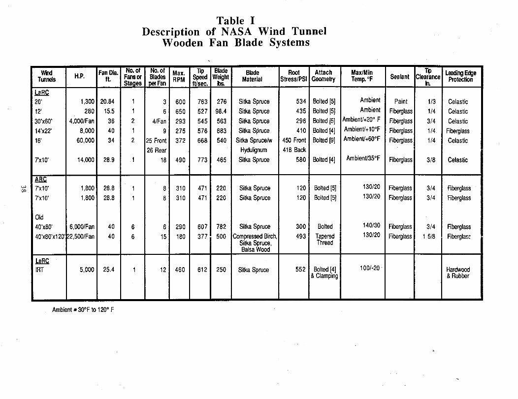
Table I
Description of NASA Wind TunnelWooden Fan Blade Systems
Wzxl H.P. FanDia.Tunnels ft.
LaRC20' 1,300 20.84
12' 280 15.5
30'X60' 4,000/Fan 36
14'x22' 8,000 40
16' 60,000 34
7'x10' 14,000 28.9
No.ofFansorStages
1
1
2
1
2
.1
No.of Max. .tip. Blade Blade Root AttachBlades RPM Speed Weight Material Stress/PSI GeomelryperFan ft/sec. 10s.
3 600 763 276 SitkaSpruce 534 Bolted[5]
6 650 527 98.4 SitkaSpruce 435 Bolted[5]
4/Fan 293 545 563 SitkaSpruce 296 Bolted[5]
9 275 576 683 SitkaSl_ruce 410 Bolted[4]
25 Front 372 668 540 SitkaSpruce_N 450 Front Bolted[9]
26 Rear Hydulignum 418 Back
18 490 773 465 SitkaSpruce 580 Bolted[4]
Max/MinTemp.°F
Ambient
Ambient
Ambient]+20° F
Ambient]+10°F
Ambient/+60°F
Ambient]35°F
Sealant
Paint
Fiberglass
Fiberglass
Fiberglass
Fiberglass
Fiberglass
ClearanceIn.
1/3
1/4
3/4
1/4
1/4
3/8
LeadingEdgeProtection
Celastic
Celastic
Celastic
FiberglassCelastic
Celastic
ARC7'x10' 1,800 28.8
7'x10' 1,800 28.8
8 310 471 220 SitkaSpruce 120 Bolted[5]
8 310 471 220 SitkaSpruce 120 Bolted[5]
130/20
130/20Fiberglass
Fiberglass
3/4
3/4
Fiberglass
Rberglass
Old
40'x80' 6,000/Fan 40
40'x80'x120'_32,500/Fan 40
LeRCIRT 5,000 25.4
6 290 607 782 SitkaSpruce 300 Bolted
15 180 377 500 CompressedBirch, 493 Ta_r_SitkaSpruce, T_eadvBalsaWood
12 460 612 250 SitkaSpruce 552 Bolted[4]& Clamping
140/30
130/20
100/-20 -
Fiberglass
Fiberglass
3/4
1 5/8
Rberglass
Fiberglas:
Hardwood& Rubber
Ambient,, 30°Fto 120° F
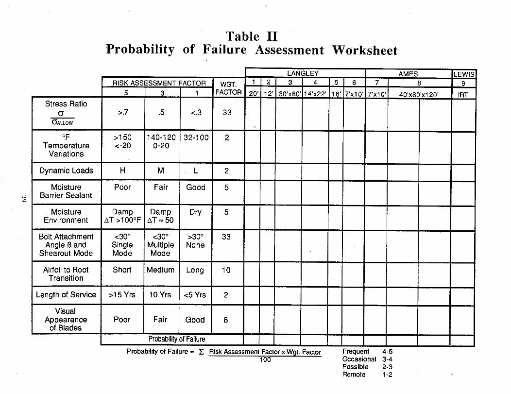
Stress Ratio
(_ALLOW
oF
TemperatureVariations
Dynamic Loads
MoistureBarrier Sealant
MoistureEnvironment
Table IIProbability of Failure Assessment
RISK ASSESSMENT FACTOR WGT. 1 2
5 3 1 FACTOR 20' 12'
>.7 .5 <.3 33
>150 140-120 32-100 ! 2<-20 0-20
H M L 2
Poor Fair Good 5
Damp Damp Dry 5AT >100°F AT = 50
Bolt Attachment <30 ° <30 ° >30 °
Angle 13and Single Multiple NoneShearout Mode Mode Mode
Worksheet
Airfoil to RootTransition
Length of Service
Visual
Appearanceof Blades
33
Short Medium Long 10
>15 Yrs 10 Yrs <5 Yrs 2
Poor Fair Good 8
Probability of Failure
Probability of Failure = ]£ Risk Assessment Factor x Wgt. Factor100
LANGLEY
3 4 5 6 7
30'x60' 14'x22 ° 16' 7'x10' 7'x10 °
AMES
8
40'x80'x120'
Frequent 4-5Occasional 3-4Possible 2-3Remote 1-2
LEWIS9
IRT

.#-o
Table II- AProbability of Failure Assessment for
Wooden Fan Blade SystemsNASA
LANGLEYi
RISK ASSESSMENT FACTOR WGT. 1 2 3 4 5 6 7
5 3 1 FACTOR 20' 12' 30'x60' 14'x22' 16' 7'x10' 7'x10'
,5 <.3 33 2.5 2.3 1.3 3 3 4 1
140-120 32-100 2 1.5 1.5 2 2 5 5 30-20
AMES LEWI_8 9
40'x80'x120' IRTOld New
1 1 1
3 3 5
M L 2 1.5 2 3 3.5 4.5 2.5 1 5 3
Fair Good 5 4.5 3,5 3 2.5 .5 1.2 3 3 1
Damp Dry 5 5 5 5 5 5 5 1AT = 50
<30 ° >30 °Multiple NoneMode
2
5
1 1 4
Stress Ratio
(_ >.7(_ALL0W
°F >150
Temperature <-20Variations
Dynamic Loads H
Moisture PoorBarrier Sealant
Moisture DampEnvironment AT >100°F
Bolt Attachment <30 °
Angle 13and SingleShearout Mode Mode
Airfoil to Root ShortTransition
Length of Service
Visual
Appearanceof Blades
33 3.5 2.5 3 3 3 5 1 1 1
Medium Long 10 3 2.5 2 3.5 1.5 2 1 1 1
>15Yrs 10Yrs <5Yrs 2 5 5 5 4.5 1.5 1 5
5
1 1 3
2
3.7 1.2
FrequentOccasionalPossibleRemote
4-53-42-31-2
1.2
Poor Fair Good 8 4 1.5 3 1.5 1
Probabilityof Failure 3.2 2.5 2.4 3 2.7
Probability of Failure = _£ Risk Assessment Factor x Wgt. Factor100
5 1 5
1
1.3
5
3.3

TABLE III- MECHANICAL PROPERTIES
Tension, PSi
II Grain J_Grain
Compression, PSI
II Grain
Shear, PSI
0
7O F
Normal Tangential
Sitka Spruce, 8% M.C.
Hydulignum (1) & (2)
0% Crossply (4)
25% Crossply (5)
50% Crossply (5)
11,986
30,085
30,453
21,975
419
(3)11,718
19,529
6,897
17,135
15,959
13,842
(3)
5,975
6,676
8,444
1,269
3,324
1,767
1,682
0
200 F
Sitka Spruce, 8% M.C.
Hydulignum (1) & (2)
25% Crossply (6)
6,592
21,691
230
7,529
3,793
13,235
(3)
4,769
698
2,000
(1) Minimum Values
(2) Minimum of 5 Specimens
(3) Data Not Avaliable
(4) Source - Product Literature
(5) Source- Certification Test Report
(6) Source - In-House Test Report

TABLE IV
Allowable Stress for Sitka Spruce as Developed for the LeRC 16 Ft. Tunnel Blades
Mechanical
Property
F b" Extreme fiberIn bending
F - Tension IIt
to grain
F - Compression IIC
to greln
F -Tenslon .Lt
to grain
F - Compression JC
to grain
F - HodzontsiV
sheer II tograin
E - Modulus ofelasticity
Clear WoodStrengthValue, Psi
5660(12)s549 ( )
56603549
26701549
250168
279279
757610
$1.2x10
Strength@
12% MoistureContent, Psi
(3)(1.81)
10,2455424
(1.81)
10,2455424
(2.10)507O3253
(1.51)
378264
(2.07)578578
(1.51)1143770
(1.27) $1.6x10
Strength@
8% MoistureContent, Psi
(1.17)
11,9867516
(1.17)
11,9867516
(1.23)68974001
(1.11)419282
(1.18)681681
(1.11)126985S
(1.07) s1.7x10
Factor forSpecificGravity
(1.00)
7616
(1.oo)7516
(1.oo)4001
(1.oo)282
(1.00)681
(1,00)855
(1.00) s1.7xi0
StrengthRatio
(.54)
4058
(.36)2706
(.69)2761
(.SO)141
(1.oo)681
(.so)427
(1.00) $1.7x10
Durationof LoadFactor
(.70)
2841
(.70)1894
(.87)1850
(.70)
99
(1.16)791
(.70)
299
(1.00) e1.7x10
Adjustment Factors
Man.
& Use
(.77)
2188
(3"/)1458
(.80)1480
(.89)88
(.91)719
(.89)266
(1.00) s1.7x10
Stress End_oncentration Position
1/d Effect ofTemperature
(4)(1.00) (1.00) (1.00) (1.00)
2188 2188 2188 (.55) (5)
(1.00) (1.00) (1.00) (1.00)1468 1468 (.55) (.65)
(1.00) (1.00) (1.00) (1.00)
1480 1480 1480 (.55)
(1.00) (1.00) (1.00) (1.00)
88 88 88 (.ss)
(1.00) (.67) (1.00)719 482 482
(.44) (1.00) (1.00)117 117 117
(1.oo)(.ss)
(1.00)
(.ss)
(1.00) s (1.00) s (1.06) s (1.00)1.7x10 1.7xl 0 1.8x10 (1.00)
AllowStress,Psi
2188
1203
1458
802
1480
814
88
48
482
265
117
64
$1.8xl 0
$1.8xl 0
(1) Average Strength(2) 1% Strength(3) ( ) Adjustment Factor
(4) 70° F
(5) 180 ° F

TABLE V- DESIGN LOAD CASES (Concluded)
Cause or Condition
Turning VanesOverturnUnderturn
Steady
_ Transie_nt.__ Stat 0
To- n- :_-¢ ,,,_ u.i
>IP
Comments
Drive Shaft Wake forExternal Motors
>IP
Fan ContractionCircular Cross-SectionSquare to Circle Trans.
Nose Cone & Supports
ASAP
ASNP
NP
NP
NP
IGV or Stator Wakes
EGV
Drive SupportsFan DownstreamFan Upstream
Off Design Blade Angle Setting
AS - AsymmetricIP - Once per RevNP - N Times per Rev.
IGV's or Stators for Multi-Stage Fans
Usually Flow Angle Distortion
Wake Caused Potential Flow Caused
x AS
BL- Boundary LayerWT - Wind TunnelEGV - Exit Guide Vanes
Variable Pitch Fans or VC IGV's;Off-Design Loading Distributions
IGV - Inlet Guide VanesVC IGV - Variable Camber IGV's

TABLE V
Transient
Cause or Condition
Starting
¢/)¢:: ,-O"O (gL
°-=____X
- DESIGN LOAD CASES
SteadyState
c0 .= ..: ommentsn- o o u.IuJ e_
Normal Controlled Accel.Decel.
X X
Emergency or Fast StopOpen-Circuit Coast DownDynamic BrakingAerobrakesDrive Shaft Braking
X X
Transferring Frequency ofInput Electric Power
X
Pulses due to Solid-State
Power Supplies
X X
Model Support Wakes
Wind Tunnel Growth Boundary
Layer
Diffusser Problems
Poor designModel induced
AS - AsymmetricIP- Once per RevNP - N Times per Rev.
Depends on Rate of Change of AirspeedControls
Large Load Reversals Can Occur
Variable Freq. Power to Constant Freq.Power & Back
Can be Especially Bad at Low Speeds
>IP
A6,> 1P
>IP
Symmetrical for Single Fan W.T.'s> 1 P for Multi-Fan W.T.'s
BL - Boundary LayerWT - Wind TunnelEGV - Exit Guide Vanes
IGV - Inlet Guide VanesVC IGV - Variable Camber IGV's

85.37 ft
30 x 33 ft
228.12 ft b
18.64 ft xi
21.64 ft
72.63 ft/
_ 15.87 ftx I
t 8.87 ft
Figure I. - NASA Ames Research Center - 7- by lO-Foot Subsonic Wind Tunnel

//
/
//
//
//
//
//
,4\
\\
\\
\\
! .... i...... .i .......... A
i i
/

m
\
ACOUSTICAL
BAFFLES
FANOUTLET
Figure 3. - NASA Langley Research CenterHigh Speed 7- by lO-Foot High Speed Wind Tunnel

o_
Lauun2 pu[M u[ds Le3L_aaA_oo3-0_ aa_ua3 q3_ase_ _aL6Ue3 VSVN - "_ a_n6L3
CO

ORIGINAL PAGE ISOf: poO_ QUAUTY
..-.
I'((_A_, t,o, ,o, L
I
TestSection
THIRD FLOOR PLAN
Figure 5. - NASA Langley Research Center12-Foot Low-Speed Wind Tunnel
49

0
% /I/
35.5
434.5'i
,IP"
T222'
Figure 6. - NASA Langley Research Center30- by 60-Foot Wind Tunnel

.-EXHAUST TOWER/---9000 H P DRIVE SYSTEM
AND HUB
Ln SCREENS
CONTROL
\_---AIR INLET
FLOW CONTROL VANES
EENTRY BELL
ODEL SUPPORT
_-----GROUN D BELT
MODEL PREPARATION ANDSTATIC TEST AREA
Figure 7. - NASA Langley Research Center14- by 22-Foot Subsonic Wind Tunnel
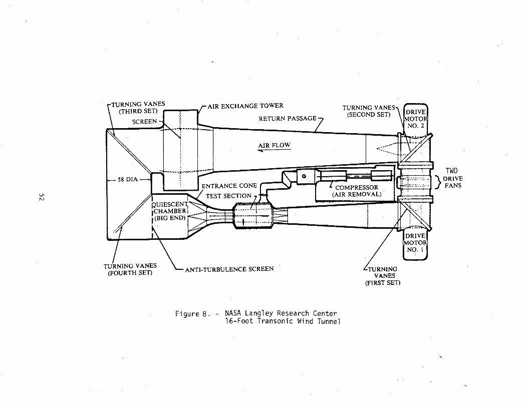
L,n
N)
[RNING VANES
(THIRD SET)
SCREEN :!
58 DIA
,QU
C HAMBER
(BIG END)
kIR EXCHANGE TOWER
RETURN
AIR FLOW
ENTRANCE CONE
TEST SECTION
TURNING VANES-_
(SECOND SET) \ MOToRIDRIVEI
NO. 21
-4#-- +_/
COMPRESSOR
(AIR REMOVAL)
TWO
DRIVEFANS
TURNING VANES
(FOURTH SET)ANTI-TURBULENCE SCREEN NG
VANES
(FIRST SET)
Figure 8. - NASA Langley Research Center16-Foot Transonic Wind Tunnel
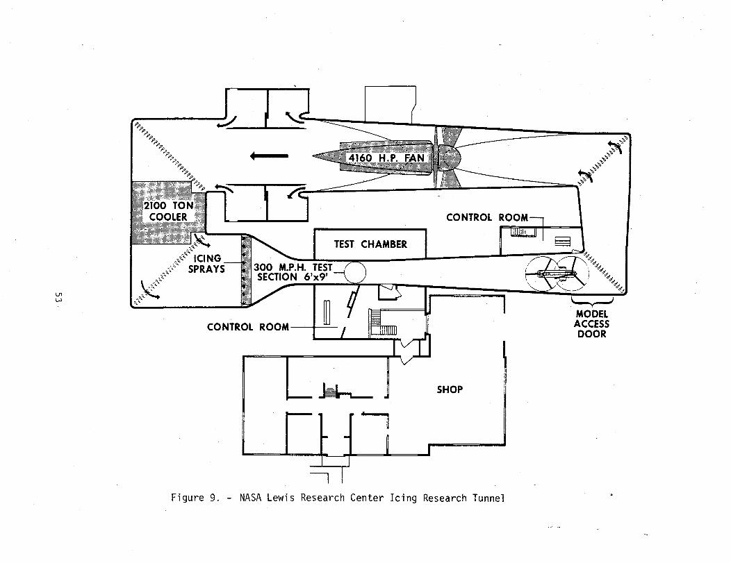
4160 H.P.
2100 TONCOOLER CONTROL
TEST CHAMBER
300 M.P.H. TEST._,SECTION 6'x9'
CONTROL
1tI
SHOP
Figure 9. - NASA Lewis Research Center Icing Research Tunnel
MODELACCESSDOOR

Hazard Probability Definitions Numerical Ranges
Assigned
The probability that a hazard will occur during
the planned life expectancy of the system. The
probability level is qualitative based uponengineering judgment with appropriate guidelines
as follows:
Frequent Likely to occur frequently. Thisis the worst case for no or inadequatemechanical or electrical interlocks, and
standard operating procedures to preclude
a mishap from occurring.
Occasional - Likely to occur sometime in life
of item. This is the lowest level given if
there are no or inadequate mechanical meansor electrical interlocks to preclude a mishap
from occurring but there are approved
standard operating procedures for operators
to use.
Reasonably Probable - Unlikely to occur but
possible. This is the lowest level given toelectrical interlocks when they are adequate
preclude the mishap from occurring.
Remote So unlikely, it can be assumed that
this hazard will not be experienced. Used
when there is a positive mechanical means or
there are adequate electrical interlocks and
procedures to preclude a mishap from
occurring.
4-5
3-4
2-3
1-2
Figure 10. - Hazard Probability Definitions and Numerical
Ranges assigned for use with Table II
54
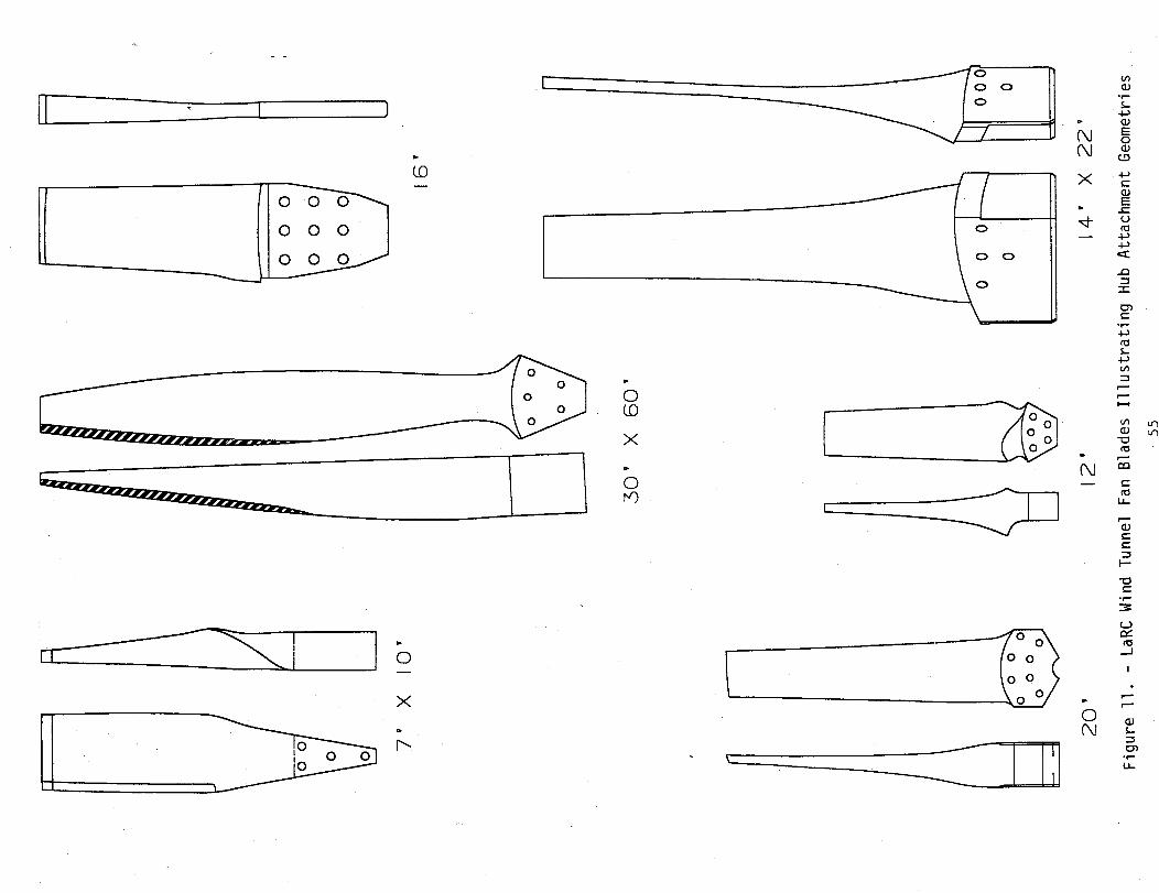
F
II°°-_mIooo- I
LO
_mmm m
El-- I o
x
o
r.f0
0 0
o
C_
X
b
0(..0
X
0m')
[h
L
° i-,,,,
E
r',J
o0,,J
o
___¢-
E
cJ
"-I-
¢-°r--
t_
th
r--
r--
r--
U-
r--
F-
°_-
r__J
r--
°r-
u-

suaa3,_,ed aLoH 3,[08 _,ua,_a.C_.LO ao_sapoN aanL.Le-I _,no-aeeqs 6u.t_,ea_,snt[l sa.La_,amoa9 3,uamqoeo,_,V qnH - "ZI aanB.L-I
_@@6J 3NSN@@ -4G©6J 3Ng_-JI S
/ Hi i
,' II
I i
I I
' I
I I
I !
t i
L.!!• i
i l
/
/f
F
F
/i/
/
J _i , I
@i
I
i
P'4
i i"
I I
I I
, _ _
I ,
L2! _

Old Design Modified Design(Different View Angle)
Figure 13, - Finite Element Models of the transition/butt regionsfor the NASA Langley Research Center 7- by lO-Footwind tunnel fan blade

CO
Sheer
strength,
psl
1400
1200
1000
800
6OO
Laminated
Sitka spruceX
X
X
®
®
X X
x xX , _ X X
XX
X
40O
200
• 2 Hours at 200°F
® 18 Hours at 200°F
0 I ! ! I ! i I !75 100 125 150 175 200 225
Test tempereture, °F
Figure 14.- Shear Strength of Laminated Sitka Spruce as a Function of Temperature.

_0
I..
e.) c-c- c/)Cz)
(D
1
,8
,6
,4
,2 L
0-i00
®
® ® H
X _ ®®X_O_ X
XT rain
Stress ratio = = 0,iT mox
®
o Douglos fir - Lominoted-glue sheor T = 75°F "
• Sitko spruce - Lominoted-glue sheor T = 75°F o--,
x Sitko spruce - Lominoted-glue sheorT = 135°F
H Sitko spruce - Lominoted-glue sheor T = 200°F
m Sitko spruce - Edge-notch tension T = 75°F
I I I I I I I I
101 102 103 104 105 106 107 108
Cycles to foilure
Figure 15..- Fatigue Strength of Laminated Sitka Spruce and Douglas Fir

2
_JT--'--'--"
Constants
Modulus
E 1
E 2
E3
Shear Modulus
G12
G13
G22
Poisson's Ratio
IJ.12
l_13
32
23
!1.31
!_21
Units
psi
psi
psi
psi
psi
psi
Sitka Spruce
1,772,000
87,000
154,000
117,000
120,O00
7,100
Hyduli_clnum25% Cross Ply
2,350,000
330,000
780,000
400,000
400,000
150,000
.441 .15
.375 .25
.471 .33
.248 .14
.034 .08
.022 .021
Figure 16. Elastic MaterialRoom Temperature
Constants Used in Orthotropic Analyses,- 8% Moisture Content
6o
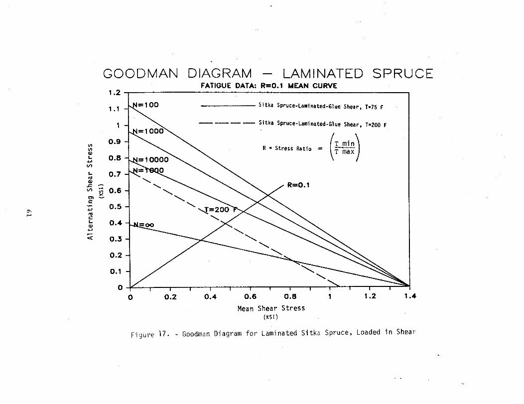
GOODMAN
1.2
DIAGRAM -- LAMINATEDFATIGUE DATA: R=0.1 MEAN CURVE
SPRUCE
1.1
0.9
0.8
0.7
_0.6
_ o.5
e-
s. 0.4_J4Jr,.-
< 0,3
0.2
0.1
0
1 O0 SitkaSpruce-Laminated-GlueShear,T-7SF
SitkaSpruce-Laminated-GlueShear,T=200F
/_ min_R : StressRatio --- max"lI
R=0.1
I I ! I 1 I ''_ I I
0 0.2 0.4 0.6 0.8 1 1.2 1.4
Mean Shear Stress
(KSI)
Figure 17. - Goodman Diagram for Laminated Sitka Spruce, Loaded in Shear

7 X 10 FAN BLADE
CHARACTERIZATION OF CYCLIC LOADING
TXZpS_
1200
8O0
400
I
"_min _a x + *rot nR = --. 0.8 "Cmean- Z -- 1010 psi
Tlnax
Tal t -- 140 psi
i/I
_alt
2 per/rev
. At RPM (30 mln)
Ttm
Figure 18. - Cyclic Shear Stress in Region of Highest Loaded Fan Blade Attachment
Hole for the NASA Langley Research Center 7- by lO-Foot High SpeedWind Tunnel during Operation at 475 RPM. _

--T = 75" F
D-
IZO0
I000
L
800
t-
c
ocL
600 N = I0
6N=IO
4-00
I-ZOO
Constant Life
-L_lne_ (c_cle_)
OPERATION CYCLES
__T I 200" II'
R=O
Time
PER/REV CYCLES
R = . IT_z
/
O
I I ® I I I300 600 900 1200 1500
Mean Shear Stress, (psi)
Figure 19o - Goodman Diagram for the 7- by lO-Foot Wind Tunnel Laminated Spruce BladesIllustrating Fatigue Life Predictions for Old and New-Design..

NOTE: Samples Held at 90% Relative
Humidity for 91 Days Prior to Test
0
.-.J
c'-
0"3.r-
(lJ
c"
(1J
U
0
4
6
lO
12
14
16
175° F
70o F
\\
\
\\
\ \\
\z,
\
_ 2Coai_--Pol_e st_r
/_ with Glass
.--._
\
\\.. ted
_2 Coats Polyester
with G1 ass
Uncoated
................. L................... I .... j .......... _.0 4 8 12 16
Time - Days
Figure 20. - Coating Effectiveness at Room and Elevated Temperatures forSitka Spruce Dried Over H2 SO4 ( 0% Relative Humidity)
20
66

_IF{ll£EiXCL{IIII I]III Ii££ I C I£11{iVfill.hiIIC_-1£$T $_PLIE _EfiFORI_,HCIE OF EACH COAT IKS
I(I) - i ....
v= YIIII£
O0
II}
• Oi)Ill
"51)Ill
z 40
2O
I0
0o
BESTMEE
;'*.i;; ..... " ..................................
•".'...-:'............ _ ..........................
....... -......................... "'" ........................ _t. 4PH/2G•.,. "..... • "'-........ ".".'.,.,.,v..-.......,......:. A .......
<> .......o ........"'.. ""# _iii'< ._.."_.. ....... ".............. "......... A BPH
"i'_- 0 "k:.... ""0 ......
IO0
DFIYS
G - .005" Fiberglas_Cloth
PH - Polyester Hetro,72
EW - Epoxy WestSystem Resin
V - Super SparVarnish
Eu - Epoxy Epon 815with curing
agent u
PL -Polyester Lamina
ED -Epoxy Epon 828wi_h curing
agent Delta
FIGURE 20.- Continued.

S4.P
qp-I.
4_
Z
4.1laal
I=
0.
"" -"---- LJ .... L) _-'" I
I
s---sEn
0p.-

"-4
0 0|.3% 18.8%
0 0 0 ,----II_ Centrifuga]Force
0 0 08.4% 8.8 % 15.S%
Figure 22. - Attachment bolt loads (% of total load) for the NASA LangleyResearch Center 16-Foot Wind Tunnel fan blades.
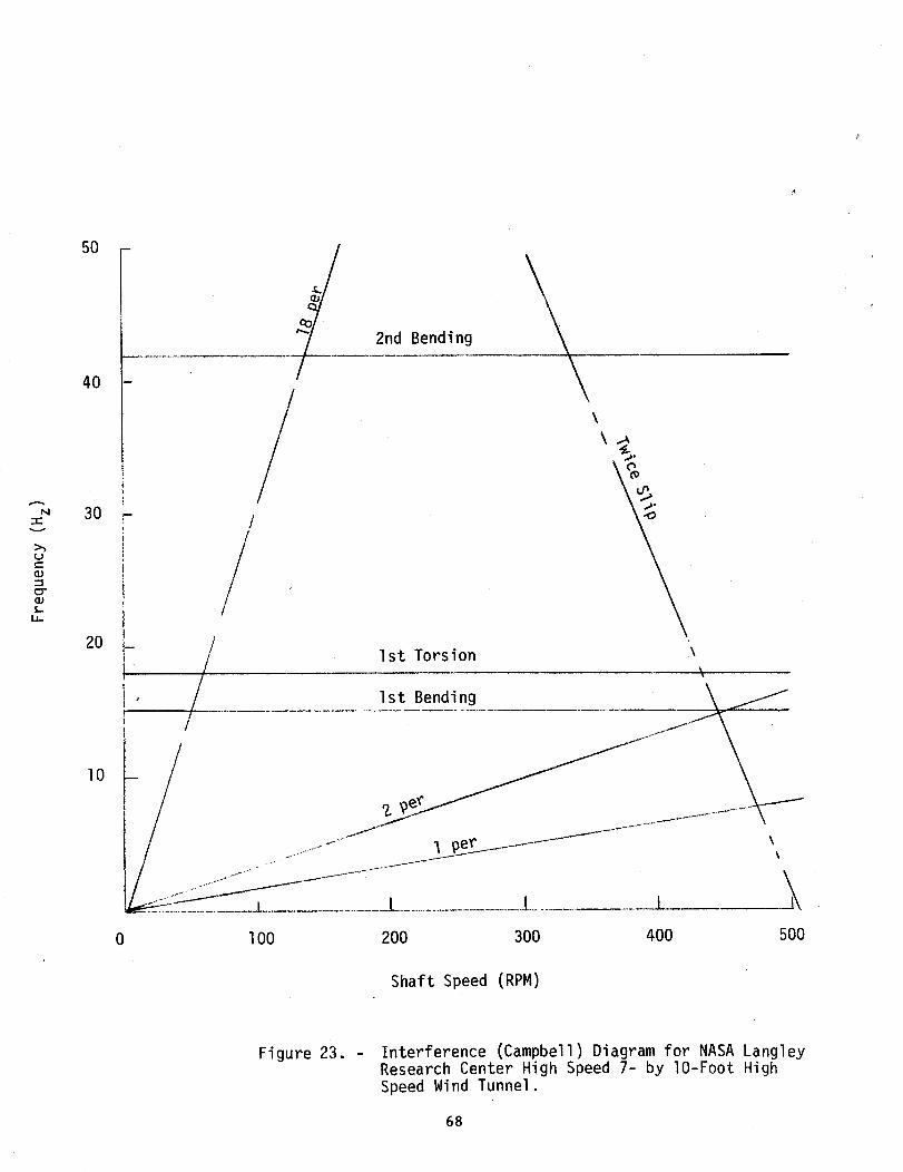
-rv
(--(D
c;r
i,
50
40
30
20
lO
FD
_m
yj
///
2nd Bending
\
/ Ist Torsion \\
1st Bending . \ __
.............._J "1 9er._ j\
\
L..........................I I
0 lO0 200 300 400 500
Shaft Speed (RPM)
Figure 23. - Interference (Campbell) Diagram for NASA Langley
Research Center High Speed 7- by lO-Foot High
Speed Wind Tunnel.
68

N/kSA_O?_C_ _AOfTllr_sTrat_l
1. Report No.
NASA TM- 104059
4. Title and Subtitle
Report Documentation Page
2. Government Accession No. 3. Recipient's Catalog No.
5. Report Date
Structural Integrity of Wind Tunnel Wooden
Fan Blades
7. Author(s)Clarence P. Young, Jr., Robert T. Wingate, Kenneth W.
Mort, James R. Rooker, and Harold E. Zager
April 1991
6. Performing Organization Code
8. Performing Organization Report No.
9. Performing Organization Name and Address
NASA Langley Research Center
Hampton, VA 23665-5225
12. Sponsoring Agency Name and Address
National Aeronautics and Space Administration
Washington, DC 20546-0001
10. Work Unit No.
505-59-85-01
11. Contract or Grant No.
13. Ty_ of Report and Period Coverod
Technical Memorandum
14. Sponsoring ._gency Code
15. Supplementaw NotesClarence P. Young, Jr.: Langley Research Center, Hampton, Virginia; currently
VisitinE Associate Professor, North Carolina State University.
Robert T. Wingate and James R. Rooker: Langley Research Center, Hampton, Virginia.
Kenneth W. Mort: Ames Research Center, Moffett Field, California.
Harold E. Zager: Lewis Research Center, Cleveland, Ohio.
16. Abstract
This report presents information compiled by the NASA Inter-Center Committee on
Structural Integrity of Wooden Fan Blades and is intended for use as a guide in
design, fabrication, evaluation, and assurance of fan systems using wooden blades.
A risk assessment approach for existing NASA wind tunnels with wooden fan blades is
provided. Also, state-of-the-art information is provided for wooden fan blade
design, drive system considerations, inspection and monitoring methods, and fan
blade repair. Proposed research and development activities are discussed, and
recommendations are provided which are aimed at future wooden fan blade design
activities and safely maintaining existing NASA wind-tunnel fan blades. This
report contains information that will be of value to wooden fan blade designers,
fabricators, inspectors, and wind-tunnel operations personnel.
17.'Key Words(SuggestodbyAuthor(s))
Fan Blade Failure
Wooden Fan Blades
Wind Tunnel Fan
Structural Design
19. Security Classif, (of this report)
18. Distribution Statement
Unclassified-Unlimited
Subject Category 39
_. SecuriW Cia_f. (of this pa_) 21. No. of pa_s
Unclassified
INASA FORM 1,626OCT
Unclassified 75
22. Price
A04


![BLADES [PPT]](https://img.pdfslide.us/doc/110x75/55cf9bc6550346d033a75508/blades-ppt.jpg)