Embed Size (px)
Citation preview
- 1 -
Structural health monitoring of offshore concrete structures using FBG sensors
E. Rizk1, H. Marzouk2, X. Gu3 and A. Hussein4 1 Memorial University, St. John’s, Canada 2 Ryerson University, Toronto, Canada 3 Ryerson University, Toronto, Canada 4 Memorial University, St. John’s, Canada
ABSTRACT: Health monitoring of offshore structures is a very important technique to maintain structural integrity. Early detection of damage can save lives and costly repairs. The information obtained from monitoring is generally used to plan and design maintenance activities, increase the safety, verify hypotheses, and reduce uncertainty. The current research is focused on the development and optimization of a Structural Health Monitoring technique to detect damage initiation for offshore slab-column connections. The research objective is to detect, localize and quantify flexural (service) cracks and shear cracks in slab-column connections. The experimental program is divided into three phases. The first phase is focused on detection of flexural cracks using embedded FBG sensors. Detection of flexural cracks includes the initiation of first crack as well as the initial crack width. The second phase is focused on mapping of crack patterns using FBG sensors arrays. The last phase of the experimental work includes detection and localization of shear cracks as well as quantification of high compressive (bearing) zones using 3D configuration of FBG sensors arrays. The current research presents the first phase of the experimental work. Test results revealed that embedded FBG sensors exhibited excellent performance and it was able to monitor the width and location of the first crack.
1 INTRODUCTION
The two-way slab system is a unique efficient structural system. It is economical and is widely used in different structural applications such as floors, roofs of buildings and walls of tanks. The two-way slab system is also used as a structural component in concrete offshore platforms and nuclear containment structures. A major concern of this system is localized punching shear failure at the slab-column connection. The catastrophic nature of punching shear failure has been a major concern for engineers for many years. Detecting cracks and local damages as early as possible is one of the most essential functions of a successful SHM system for a slab-column connection. Most of the previous research on SHM was carried out on one-dimensional elements such as beams. SHM of two-way slabs used for offshore construction is critical and is not fully addressed.
The current research presents different SHM techniques to detect, localize and quantify damage in two-way slab system. The experimental work is divided into three main phases. The first phase is focused on detection of the initiation of service cracks using embedded FBG sensors. The second phase is focused on mapping of service cracks patterns using bonded FBG sensors arrays. The last phase of the experimental work includes detection and localization of punching shear cracks as well as quantification of high compressive (bearing) zones using 3D
- 2 -
configuration of FBG sensors array. This paper presents the results of the first phase of the experimental work. In this work, embedded FBG sensors were applied for health monitoring of two-way concrete slab. The main objective of the experimental work is to develop a SHM technique for offshore concrete structures that enables continuous health monitoring of the structure as well as the capability to detect the width and location of first crack. Two sets of FBG and electrical strain gauge (ESG) sensors were mounted on tensile rebars. The FBG sensor is bonded onto a flattened surface at the middle of a reinforcement rebar. A different type of long FBG sensor is embedded in the tension side of the concrete slab.
2 STRUCTURAL HEALTH MONITORING & DAMAGE DETECTION
Structural Health Monitoring (SHM) is defined as the process of implementing a damage detection strategy for aerospace, civil, and mechanical engineering infrastructure. Although sometimes SHM refers to damage detection, it could be used to refer to the process of validation of the properties of new structures, long-term monitoring of an existing structure, structural control and many others. In the most general terms, damage can be defined as changes introduced into a system that adversely affects its current or future performance. Implicit in this definition is the concept that damage is not meaningful without a comparison between two different states of the system, one of which is assumed to represent the initial and often undamaged state. Identifying the presence of the damage might be considered as the first step to take preventive actions and to start the process towards understanding the root causes of the problem. A widely accepted definition of the levels of damage detection was provided by Rytter (1993). Rytter defined four levels of damage identification that are detection of the damage, localization of the damage, quantification of damage and decision-making.
3 OPTICAL FIBER BRAGG GRATING SENSORS
Fiber Bragg grating (FBG) sensors are one of many fiber optic sensor technologies that are currently being used in structural health monitoring systems. The sensors operate by detecting a shift in the wavelength of the reflected maximum due to applied strain. The ESGs are susceptible to EMI and hence unsuitable for long-distance applications. Structurally, each ESG has two wires serving as input and output ports respectively, unlike fiber Bragg grating based sensors where several sensors can be multiplexed onto the same optical fiber (Friebele 1998). Fiber Bragg gratings (FBGs) have been studied for a wide variety of mechanical sensing applications (Ansari 1998; Mufti et al. 1997; Tennyson et al. 2001) including monitoring of civil infrastructures (highways, bridges, buildings, dams, etc.). The main advantage of FBGs for mechanical sensing is that these devices perform a direct transformation of the sensed parameter to optical wavelength, independent of light levels, connector or fiber losses, or other FBGs at different wavelengths.
4 HEALTH MONITORING OF SLAB-COLUMN CONNECTION
A two-way slab is a structural element subject to biaxial bending, torsional moment, as well as membrane and shear forces. Structural monitoring of two-way slab element poses some challenges that require careful selection of effective sensors locations or a large number of sensors will be required for slab monitoring, which can be very costly. In order to reduce the monitoring costs, it is recommended to monitor only the critical damage zones in the slab. In order to minimize the number of sensors used, a strut-and-tie model could be applied to obtain the optimum number of sensors as well as the accurate sensors locations.
- 3 -
4.1 Damage locations in slab-column connections
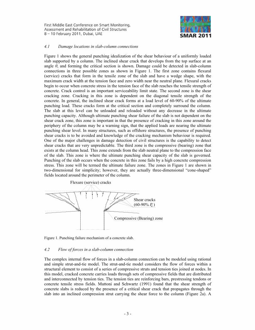
Figure 1 shows the general punching idealization of the shear behaviour of a uniformly loaded slab supported by a column. The inclined shear crack that develops from the top surface at an angle θ, and forming the critical section is shown. Damage could be detected in slab-column connections in three possible zones as shown in Figure 1. The first zone contains flexural (service) cracks that form in the tensile zone of the slab and have a wedge shape, with the maximum crack width at the tension face and zero width near the neutral plane. Flexural cracks begin to occur when concrete stress in the tension face of the slab reaches the tensile strength of concrete. Crack control is an important serviceability limit state. The second zone is the shear cracking zone. Cracking in this zone is dependent on the diagonal tensile strength of the concrete. In general, the inclined shear crack forms at a load level of 60-90% of the ultimate punching load. These cracks form at the critical section and completely surround the column. The slab at this level can be unloaded and reloaded without any decrease in the ultimate punching capacity. Although ultimate punching shear failure of the slab is not dependent on the shear crack zone, this zone is important in that the presence of cracking in this zone around the periphery of the column may be a warning sign, that the applied loads are nearing the ultimate punching shear level. In many structures, such as offshore structures, the presence of punching shear cracks is to be avoided and knowledge of the cracking mechanism behaviour is required. One of the major challenges in damage detection of civil structures is the capability to detect shear cracks that are very unpredictable. The third zone is the compressive (bearing) zone that exists at the column head. This zone extends from the slab neutral plane to the compression face of the slab. This zone is where the ultimate punching shear capacity of the slab is governed. Punching of the slab occurs when the concrete in this zone fails by a high concrete compression stress. This zone will be termed the ultimate failure zone. The zones in Figure 1 are shown in two-dimensional for simplicity; however, they are actually three-dimensional “cone-shaped” fields located around the perimeter of the column.
Flexure (service) cracks
Shear cracks(60-90% P )
Compressive (Bearing) zone
u
Figure 1. Punching failure mechanism of a concrete slab.
4.2 Flow of forces in a slab-column connection
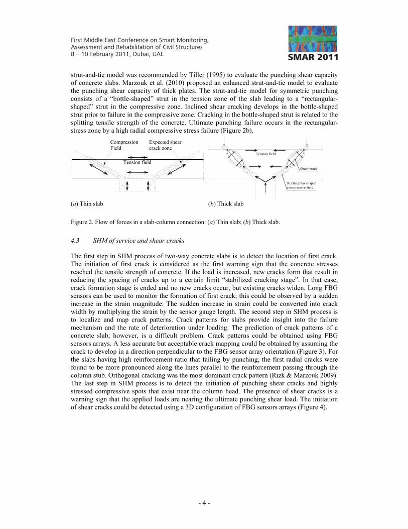
The complex internal flow of forces in a slab-column connection can be modeled using rational and simple strut-and-tie model. The strut-and-tie model considers the flow of forces within a structural element to consist of a series of compressive struts and tension ties joined at nodes. In this model, cracked concrete carries loads through sets of compressive fields that are distributed and interconnected by tension ties. The tension ties are reinforcing bars, prestressing tendons or concrete tensile stress fields. Muttoni and Schwartz (1991) found that the shear strength of concrete slabs is reduced by the presence of a critical shear crack that propagates through the slab into an inclined compression strut carrying the shear force to the column (Figure 2a). A
- 4 -
strut-and-tie model was recommended by Tiller (1995) to evaluate the punching shear capacity of concrete slabs. Marzouk et al. (2010) proposed an enhanced strut-and-tie model to evaluate the punching shear capacity of thick plates. The strut-and-tie model for symmetric punching consists of a “bottle-shaped” strut in the tension zone of the slab leading to a “rectangular-shaped” strut in the compressive zone. Inclined shear cracking develops in the bottle-shaped strut prior to failure in the compressive zone. Cracking in the bottle-shaped strut is related to the splitting tensile strength of the concrete. Ultimate punching failure occurs in the rectangular-stress zone by a high radial compressive stress failure (Figure 2b).
Expected shearcrack zone
Tension field
CompressionField
Tension field
Rectangular shapedcompressive field
Shear crack
(a) Thin slab (b) Thick slab
Figure 2. Flow of forces in a slab-column connection: (a) Thin slab; (b) Thick slab.
4.3 SHM of service and shear cracks
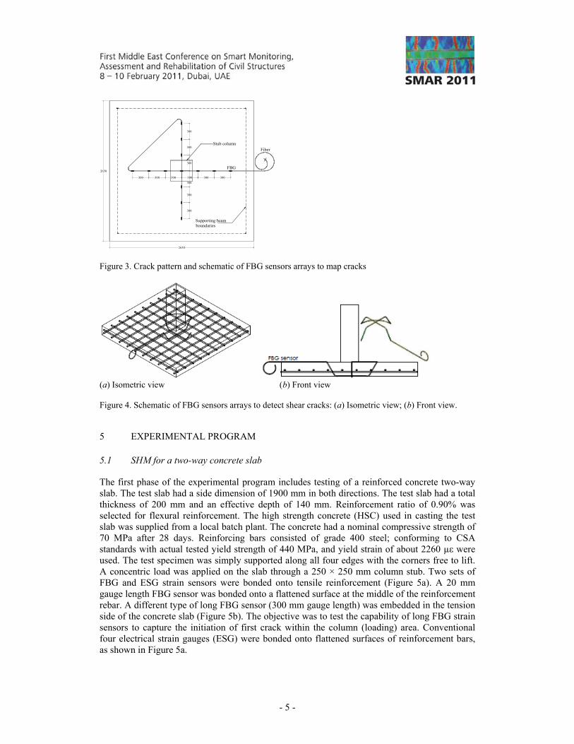
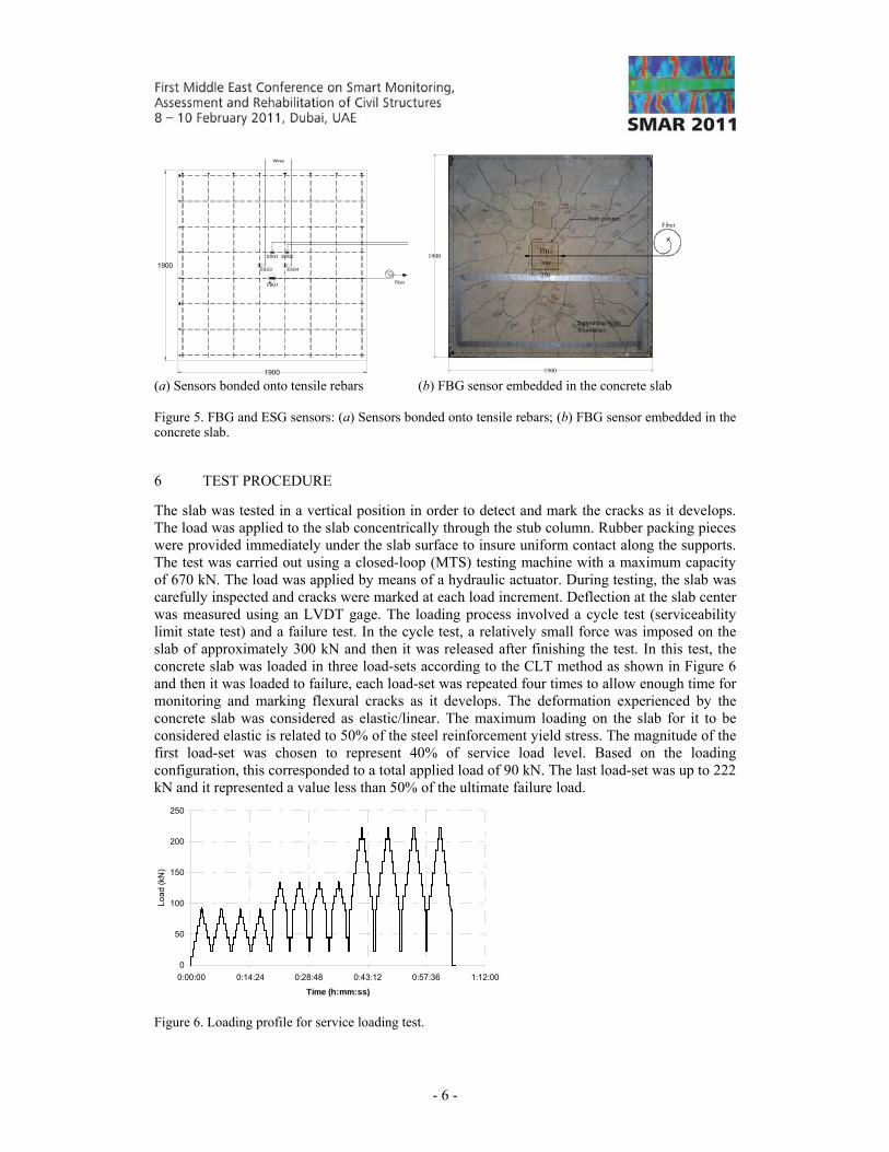
The first step in SHM process of two-way concrete slabs is to detect the location of first crack. The initiation of first crack is considered as the first warning sign that the concrete stresses reached the tensile strength of concrete. If the load is increased, new cracks form that result in reducing the spacing of cracks up to a certain limit “stabilized cracking stage”. In that case, crack formation stage is ended and no new cracks occur, but existing cracks widen. Long FBG sensors can be used to monitor the formation of first crack; this could be observed by a sudden increase in the strain magnitude. The sudden increase in strain could be converted into crack width by multiplying the strain by the sensor gauge length. The second step in SHM process is to localize and map crack patterns. Crack patterns for slabs provide insight into the failure mechanism and the rate of deterioration under loading. The prediction of crack patterns of a concrete slab; however, is a difficult problem. Crack patterns could be obtained using FBG sensors arrays. A less accurate but acceptable crack mapping could be obtained by assuming the crack to develop in a direction perpendicular to the FBG sensor array orientation (Figure 3). For the slabs having high reinforcement ratio that failing by punching, the first radial cracks were found to be more pronounced along the lines parallel to the reinforcement passing through the column stub. Orthogonal cracking was the most dominant crack pattern (Rizk & Marzouk 2009). The last step in SHM process is to detect the initiation of punching shear cracks and highly stressed compressive spots that exist near the column head. The presence of shear cracks is a warning sign that the applied loads are nearing the ultimate punching shear load. The initiation of shear cracks could be detected using a 3D configuration of FBG sensors arrays (Figure 4).
- 5 -
Stub column
Supporting beamboundaries
2650
2650
300 300 300 300 300 300
300
300
300
300
300
300
Fiber
FBG
Figure 3. Crack pattern and schematic of FBG sensors arrays to map cracks
(a) Isometric view (b) Front view
Figure 4. Schematic of FBG sensors arrays to detect shear cracks: (a) Isometric view; (b) Front view.
5 EXPERIMENTAL PROGRAM
5.1 SHM for a two-way concrete slab
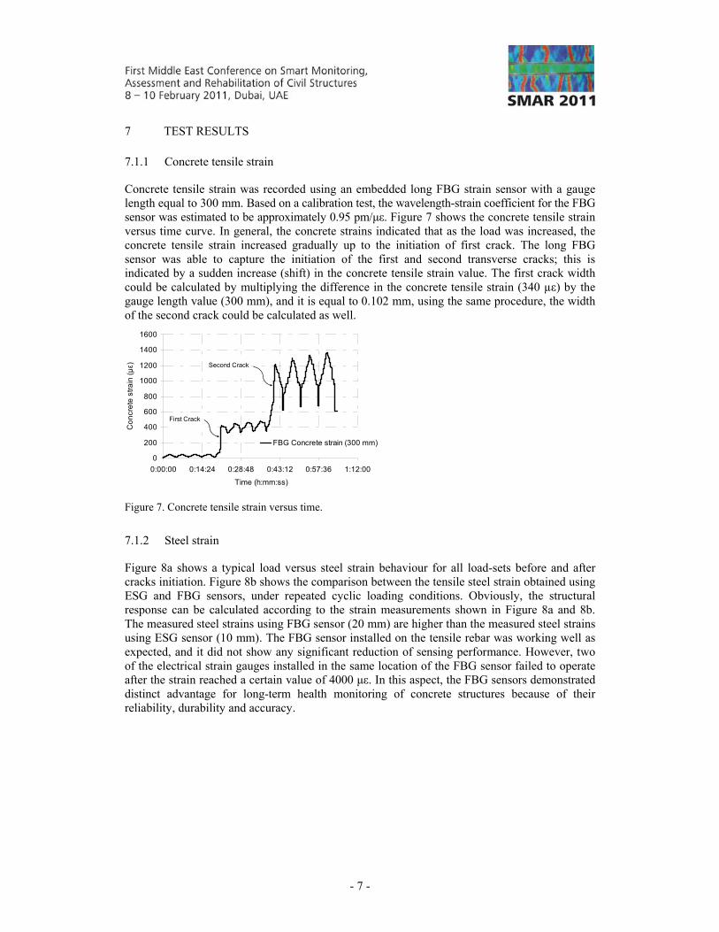
The first phase of the experimental program includes testing of a reinforced concrete two-way slab. The test slab had a side dimension of 1900 mm in both directions. The test slab had a total thickness of 200 mm and an effective depth of 140 mm. Reinforcement ratio of 0.90% was selected for flexural reinforcement. The high strength concrete (HSC) used in casting the test slab was supplied from a local batch plant. The concrete had a nominal compressive strength of 70 MPa after 28 days. Reinforcing bars consisted of grade 400 steel; conforming to CSA standards with actual tested yield strength of 440 MPa, and yield strain of about 2260 µε were used. The test specimen was simply supported along all four edges with the corners free to lift. A concentric load was applied on the slab through a 250 × 250 mm column stub. Two sets of FBG and ESG strain sensors were bonded onto tensile reinforcement (Figure 5a). A 20 mm gauge length FBG sensor was bonded onto a flattened surface at the middle of the reinforcement rebar. A different type of long FBG sensor (300 mm gauge length) was embedded in the tension side of the concrete slab (Figure 5b). The objective was to test the capability of long FBG strain sensors to capture the initiation of first crack within the column (loading) area. Conventional four electrical strain gauges (ESG) were bonded onto flattened surfaces of reinforcement bars, as shown in Figure 5a.
- 6 -
1900
1900
FBG1 Fiber
ESG1 ESG2
ESG3 ESG4
Wires
Stub column
Supporting beamboundaries
1900
1900
Fiber
FBG
250
300
(a) Sensors bonded onto tensile rebars (b) FBG sensor embedded in the concrete slab
Figure 5. FBG and ESG sensors: (a) Sensors bonded onto tensile rebars; (b) FBG sensor embedded in the concrete slab.
6 TEST PROCEDURE
The slab was tested in a vertical position in order to detect and mark the cracks as it develops. The load was applied to the slab concentrically through the stub column. Rubber packing pieces were provided immediately under the slab surface to insure uniform contact along the supports. The test was carried out using a closed-loop (MTS) testing machine with a maximum capacity of 670 kN. The load was applied by means of a hydraulic actuator. During testing, the slab was carefully inspected and cracks were marked at each load increment. Deflection at the slab center was measured using an LVDT gage. The loading process involved a cycle test (serviceability limit state test) and a failure test. In the cycle test, a relatively small force was imposed on the slab of approximately 300 kN and then it was released after finishing the test. In this test, the concrete slab was loaded in three load-sets according to the CLT method as shown in Figure 6 and then it was loaded to failure, each load-set was repeated four times to allow enough time for monitoring and marking flexural cracks as it develops. The deformation experienced by the concrete slab was considered as elastic/linear. The maximum loading on the slab for it to be considered elastic is related to 50% of the steel reinforcement yield stress. The magnitude of the first load-set was chosen to represent 40% of service load level. Based on the loading configuration, this corresponded to a total applied load of 90 kN. The last load-set was up to 222 kN and it represented a value less than 50% of the ultimate failure load.
0
50
100
150
200
250
0:00:00 0:14:24 0:28:48 0:43:12 0:57:36 1:12:00
Time (h:mm:ss)
Lo
ad
(kN
)
Figure 6. Loading profile for service loading test.
- 7 -
7 TEST RESULTS
7.1.1 Concrete tensile strain
Concrete tensile strain was recorded using an embedded long FBG strain sensor with a gauge length equal to 300 mm. Based on a calibration test, the wavelength-strain coefficient for the FBG sensor was estimated to be approximately 0.95 pm/με. Figure 7 shows the concrete tensile strain versus time curve. In general, the concrete strains indicated that as the load was increased, the concrete tensile strain increased gradually up to the initiation of first crack. The long FBG sensor was able to capture the initiation of the first and second transverse cracks; this is indicated by a sudden increase (shift) in the concrete tensile strain value. The first crack width could be calculated by multiplying the difference in the concrete tensile strain (340 µε) by the gauge length value (300 mm), and it is equal to 0.102 mm, using the same procedure, the width of the second crack could be calculated as well.
0
200
400
600
800
1000
1200
1400
1600
0:00:00 0:14:24 0:28:48 0:43:12 0:57:36 1:12:00
Time (h:mm:ss)
Co
ncr
ete
str
ain
(με)
FBG Concrete strain (300 mm)
First Crack
Second Crack
Figure 7. Concrete tensile strain versus time.
7.1.2 Steel strain
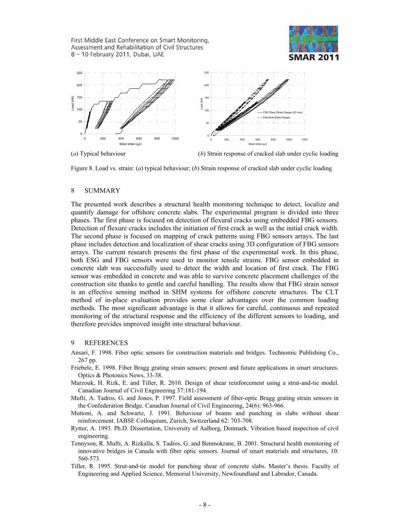
Figure 8a shows a typical load versus steel strain behaviour for all load-sets before and after cracks initiation. Figure 8b shows the comparison between the tensile steel strain obtained using ESG and FBG sensors, under repeated cyclic loading conditions. Obviously, the structural response can be calculated according to the strain measurements shown in Figure 8a and 8b. The measured steel strains using FBG sensor (20 mm) are higher than the measured steel strains using ESG sensor (10 mm). The FBG sensor installed on the tensile rebar was working well as expected, and it did not show any significant reduction of sensing performance. However, two of the electrical strain gauges installed in the same location of the FBG sensor failed to operate after the strain reached a certain value of 4000 με. In this aspect, the FBG sensors demonstrated distinct advantage for long-term health monitoring of concrete structures because of their reliability, durability and accuracy.
- 8 -
0
50
100
150
200
250
0 200 400 600 800 1000
Steel strain (με)
Lo
ad
(kN
)
0
50
100
150
200
250
0 200 400 600 800 1000 1200
Steel strain (με)
Lo
ad
(kN
)
FBG Steel Strain Gauge (20 mm)
Electrical Strain Gauge
(a) Typical behaviour (b) Strain response of cracked slab under cyclic loading
Figure 8. Load vs. strain: (a) typical behaviour; (b) Strain response of cracked slab under cyclic loading
8 SUMMARY
The presented work describes a structural health monitoring technique to detect, localize and quantify damage for offshore concrete slabs. The experimental program is divided into three phases. The first phase is focused on detection of flexural cracks using embedded FBG sensors. Detection of flexure cracks includes the initiation of first crack as well as the initial crack width. The second phase is focused on mapping of crack patterns using FBG sensors arrays. The last phase includes detection and localization of shear cracks using 3D configuration of FBG sensors arrays. The current research presents the first phase of the experimental work. In this phase, both ESG and FBG sensors were used to monitor tensile strains. FBG sensor embedded in concrete slab was successfully used to detect the width and location of first crack. The FBG sensor was embedded in concrete and was able to survive concrete placement challenges of the construction site thanks to gentle and careful handling. The results show that FBG strain sensor is an effective sensing method in SHM systems for offshore concrete structures. The CLT method of in-place evaluation provides some clear advantages over the common loading methods. The most significant advantage is that it allows for careful, continuous and repeated monitoring of the structural response and the efficiency of the different sensors to loading, and therefore provides improved insight into structural behaviour.
9 REFERENCES Ansari, F. 1998. Fiber optic sensors for construction materials and bridges. Technomic Publishing Co.,
267 pp. Friebele, E. 1998. Fiber Bragg grating strain sensors: present and future applications in smart structures.
Optics & Photonics News, 33-38. Marzouk, H. Rizk, E. and Tiller, R. 2010. Design of shear reinforcement using a strut-and-tie model.
Canadian Journal of Civil Engineering 37:181-194. Mufti, A. Tadros, G. and Jones, P. 1997. Field assessment of fiber-optic Bragg grating strain sensors in
the Confederation Bridge. Canadian Journal of Civil Engineering, 24(6): 963-966. Muttoni, A. and Schwartz, J. 1991. Behaviour of beams and punching in slabs without shear
reinforcement. IABSE Colloquium, Zurich, Switzerland 62: 703-708. Rytter, A. 1993. Ph.D. Dissertation, University of Aalborg, Denmark. Vibration based inspection of civil
engineering. Tennyson, R. Mufti, A. Rizkalla, S. Tadros, G. and Benmokrane, B. 2001. Structural health monitoring of
innovative bridges in Canada with fiber optic sensors. Journal of smart materials and structures, 10: 560-573.
Tiller, R. 1995. Strut-and-tie model for punching shear of concrete slabs. Master’s thesis. Faculty of Engineering and Applied Science, Memorial University, Newfoundland and Labrador, Canada.