Embed Size (px)
Citation preview

The Joint Advanced Materials and Structures Center of Excellence
Structural Health Monitoring for Structural Health Monitoring for Life Management of AircraftLife Management of Aircraft
--SHM System for Composite Structures SHM System for Composite Structures ––
Sridhar KrishnaswamySridhar Krishnaswamy
2The Joint Advanced Materials and Structures Center of ExcellenceNorthwestern University
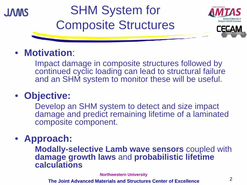
SHM System for Composite Structures
• Motivation: Impact damage in composite structures followed by continued cyclic loading can lead to structural failure and an SHM system to monitor these will be useful.
• Objective:Develop an SHM system to detect and size impact damage and predict remaining lifetime of a laminated composite component.
• Approach:Modally-selective Lamb wave sensors coupled with damage growth laws and probabilistic lifetime calculations

3The Joint Advanced Materials and Structures Center of ExcellenceNorthwestern University
FAA Sponsored Project Information
• Principal Investigators & Researchers– J.D. Achenbach– Sridhar Krishnaswamy– Isaac M. Daniel– Gabriela Petculescu, Goutham Kirikera, Li Sun
• FAA Technical Monitor– Peter Shyprykevich, Curt Davies
• Industry Participation– Boeing, Honeywell, GE, Imperium, AlphaStar Corp
4The Joint Advanced Materials and Structures Center of ExcellenceNorthwestern University
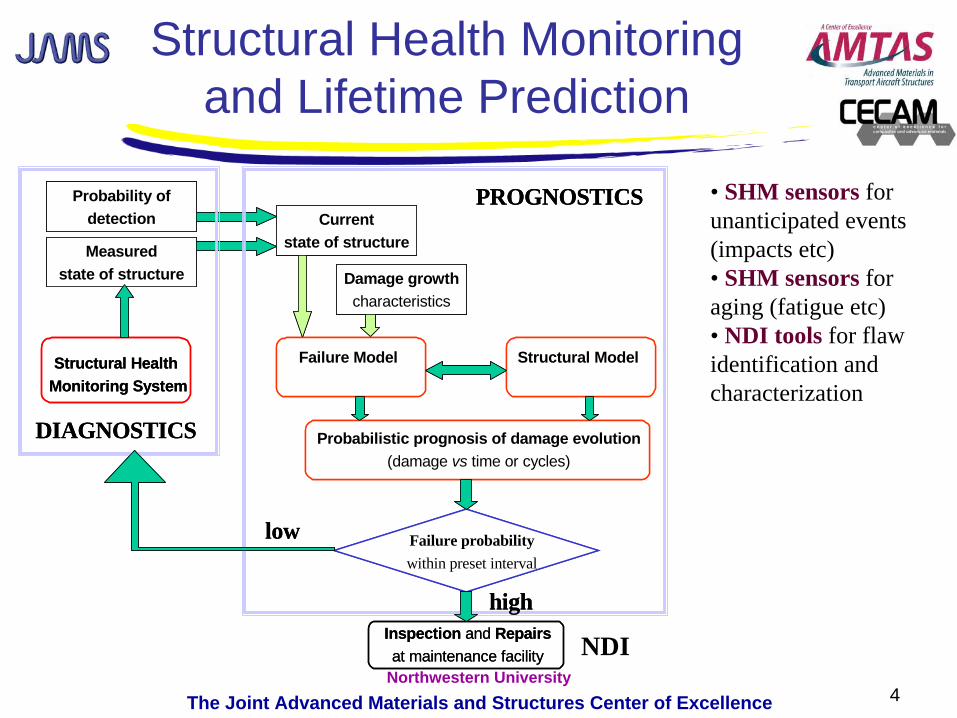
Structural Health Monitoring and Lifetime Prediction
Currentstate of structure
Damage growthcharacteristics
Structural Health Monitoring System
Inspection and Repairsat maintenance facility
Probability ofdetection
Measuredstate of structure
Failure probabilitywithin preset interval
Failure Model Structural Model
Probabilistic prognosis of damage evolution(damage vs time or cycles)
high
DIAGNOSTICS
PROGNOSTICS
low
NDI
• SHM sensors for unanticipated events (impacts etc)• SHM sensors for aging (fatigue etc)• NDI tools for flaw identification and characterization
5The Joint Advanced Materials and Structures Center of ExcellenceNorthwestern University
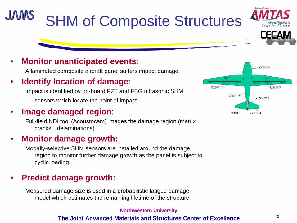
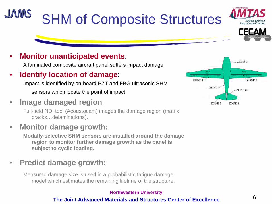
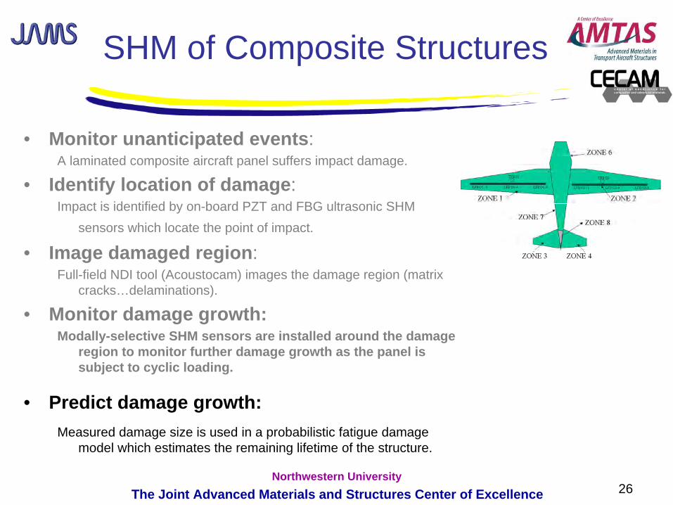
SHM of Composite Structures
• Monitor unanticipated events: A laminated composite aircraft panel suffers impact damage.
• Identify location of damage: Impact is identified by on-board PZT and FBG ultrasonic SHM
sensors which locate the point of impact.
• Image damaged region: Full-field NDI tool (Acoustocam) images the damage region (matrix
cracks…delaminations).
• Monitor damage growth:Modally-selective SHM sensors are installed around the damage
region to monitor further damage growth as the panel is subject to cyclic loading.
• Predict damage growth:Measured damage size is used in a probabilistic fatigue damage
model which estimates the remaining lifetime of the structure.
6The Joint Advanced Materials and Structures Center of ExcellenceNorthwestern University
SHM of Composite Structures
• Monitor unanticipated events: A laminated composite aircraft panel suffers impact damage.
• Identify location of damage: Impact is identified by on-board PZT and FBG ultrasonic SHM
sensors which locate the point of impact.
• Image damaged region: Full-field NDI tool (Acoustocam) images the damage region (matrix
cracks…delaminations).
• Monitor damage growth: Modally-selective SHM sensors are installed around the damage
region to monitor further damage growth as the panel is subject to cyclic loading.
• Predict damage growth:Measured damage size is used in a probabilistic fatigue damage
model which estimates the remaining lifetime of the structure.
7The Joint Advanced Materials and Structures Center of ExcellenceNorthwestern University
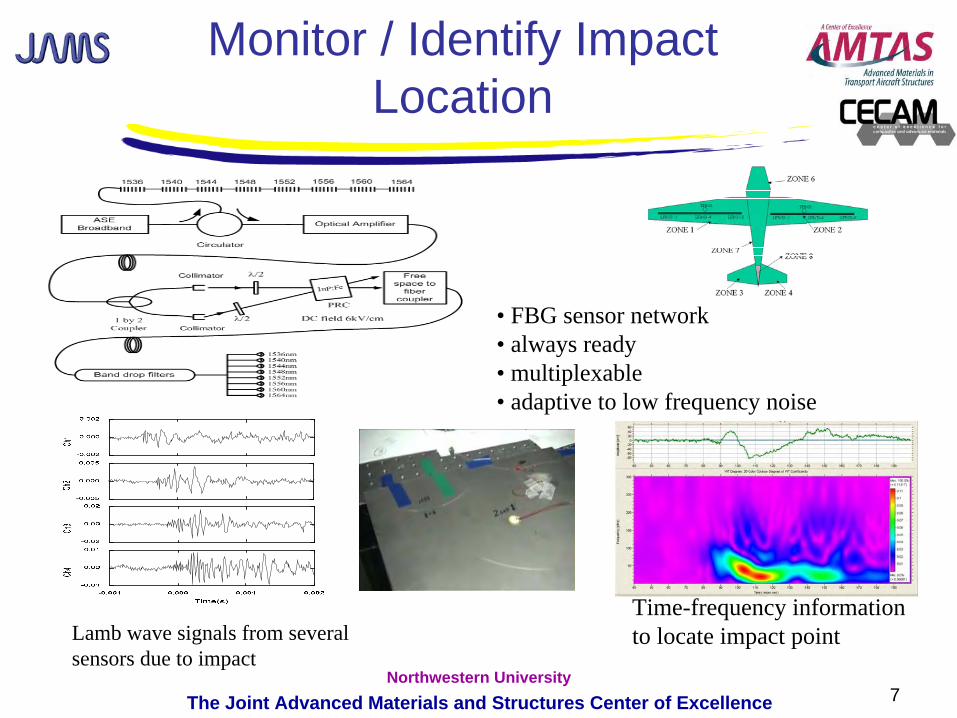
Monitor / Identify Impact Location
Time-frequency information to locate impact pointLamb wave signals from several
sensors due to impact
• FBG sensor network• always ready• multiplexable• adaptive to low frequency noise
8The Joint Advanced Materials and Structures Center of ExcellenceNorthwestern University
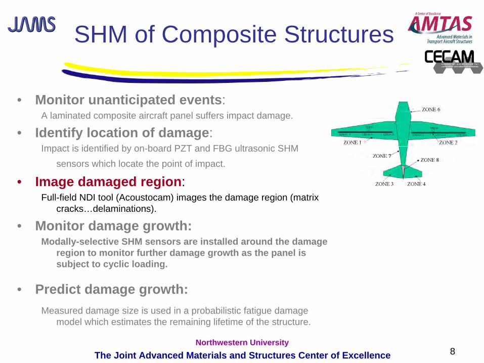
SHM of Composite Structures
• Monitor unanticipated events: A laminated composite aircraft panel suffers impact damage.
• Identify location of damage: Impact is identified by on-board PZT and FBG ultrasonic SHM
sensors which locate the point of impact.
• Image damaged region: Full-field NDI tool (Acoustocam) images the damage region (matrix
cracks…delaminations).
• Monitor damage growth: Modally-selective SHM sensors are installed around the damage
region to monitor further damage growth as the panel is subject to cyclic loading.
• Predict damage growth:Measured damage size is used in a probabilistic fatigue damage
model which estimates the remaining lifetime of the structure.
9The Joint Advanced Materials and Structures Center of ExcellenceNorthwestern University
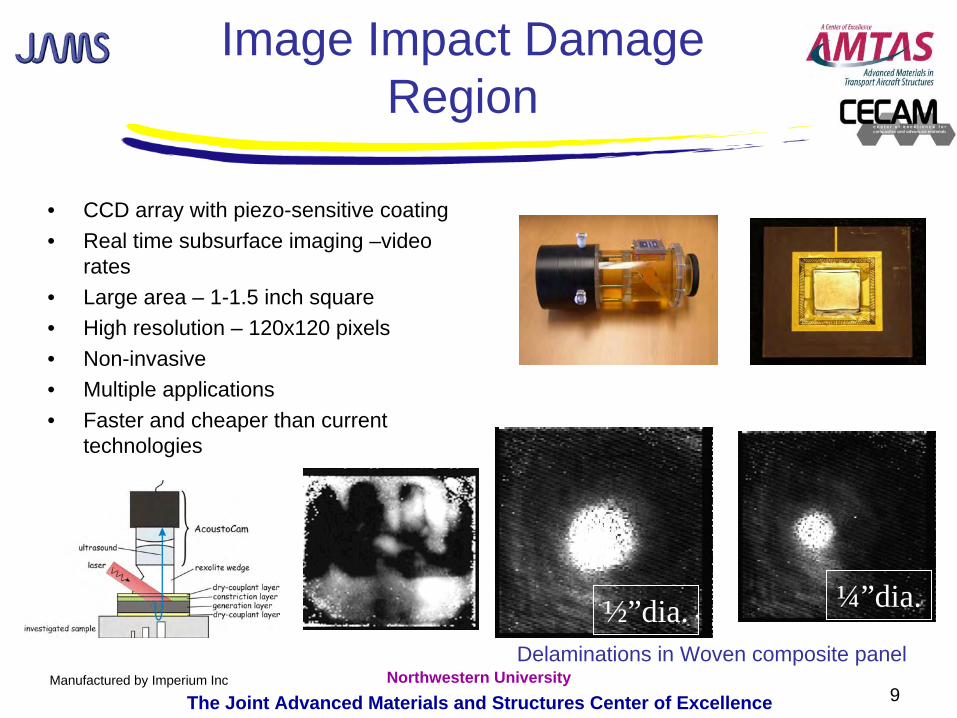
Image Impact Damage Region
• CCD array with piezo-sensitive coating• Real time subsurface imaging –video
rates• Large area – 1-1.5 inch square• High resolution – 120x120 pixels• Non-invasive• Multiple applications• Faster and cheaper than current
technologies
Manufactured by Imperium Inc
¼”dia.½”dia.Delaminations in Woven composite panel
10The Joint Advanced Materials and Structures Center of ExcellenceNorthwestern University
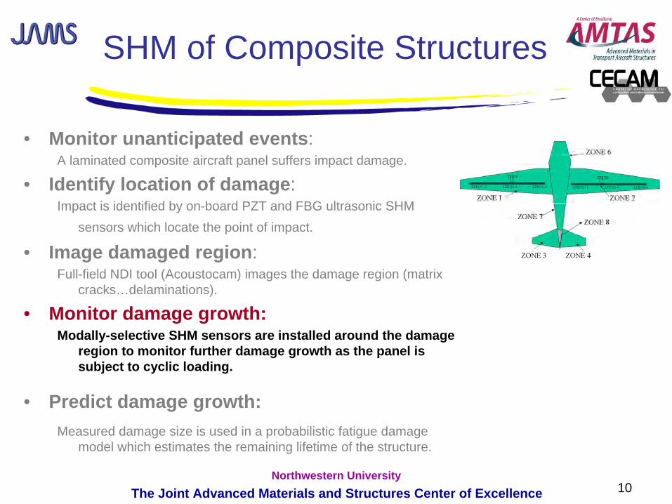
SHM of Composite Structures
• Monitor unanticipated events: A laminated composite aircraft panel suffers impact damage.
• Identify location of damage: Impact is identified by on-board PZT and FBG ultrasonic SHM
sensors which locate the point of impact.
• Image damaged region: Full-field NDI tool (Acoustocam) images the damage region (matrix
cracks…delaminations).
• Monitor damage growth:Modally-selective SHM sensors are installed around the damage
region to monitor further damage growth as the panel is subject to cyclic loading.
• Predict damage growth:Measured damage size is used in a probabilistic fatigue damage
model which estimates the remaining lifetime of the structure.
11The Joint Advanced Materials and Structures Center of ExcellenceNorthwestern University
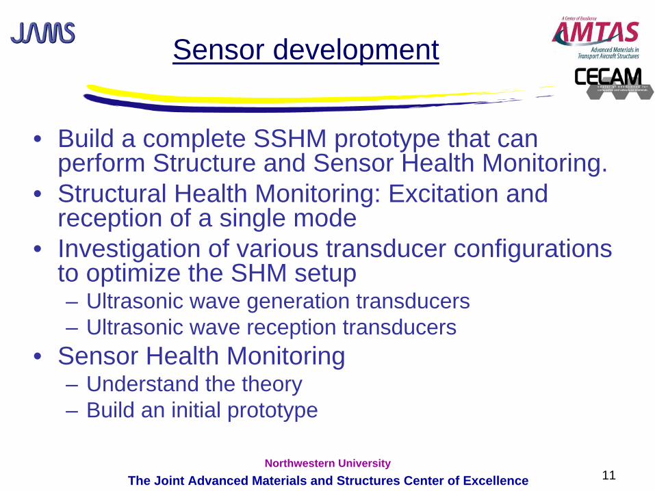
Sensor development
• Build a complete SSHM prototype that can perform Structure and Sensor Health Monitoring.
• Structural Health Monitoring: Excitation and reception of a single mode
• Investigation of various transducer configurations to optimize the SHM setup – Ultrasonic wave generation transducers– Ultrasonic wave reception transducers
• Sensor Health Monitoring – Understand the theory– Build an initial prototype
12The Joint Advanced Materials and Structures Center of ExcellenceNorthwestern University
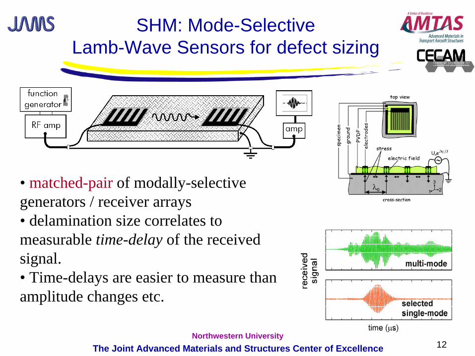
• matched-pair of modally-selective generators / receiver arrays • delamination size correlates to measurable time-delay of the received signal.• Time-delays are easier to measure than amplitude changes etc.
SHM: Mode-Selective Lamb-Wave Sensors for defect sizing
13The Joint Advanced Materials and Structures Center of ExcellenceNorthwestern University
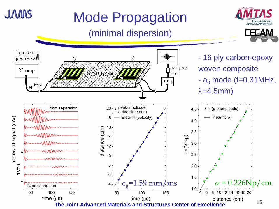
Mode Propagation(minimal dispersion)
cg
=1.59 mm/ms α = 0.226Np/cm
- 16 ply carbon-epoxywoven composite- a0 mode (f=0.31MHz,λ=4.5mm)
14The Joint Advanced Materials and Structures Center of ExcellenceNorthwestern University
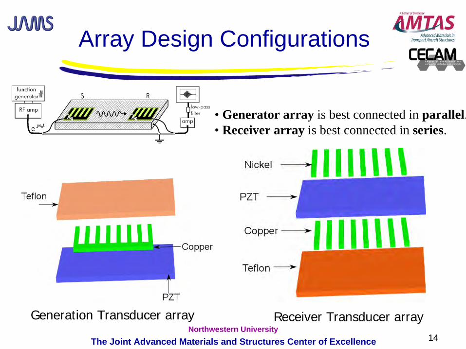
• Generator array is best connected in parallel.• Receiver array is best connected in series.
Generation Transducer array Receiver Transducer array
Array Design Configurations
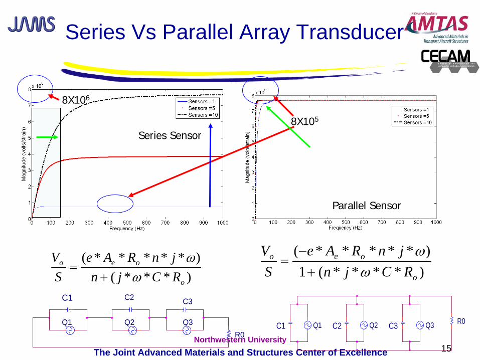
15The Joint Advanced Materials and Structures Center of ExcellenceNorthwestern University
)***()*****(
o
oeo
RCjnjnRAe
SV
ωω
+=
Series Sensor
8X10⁶
8X10⁵
Parallel Sensor
)****(1)*****(
o
oeo
RCjnjnRAe
SV
ωω
+−
=
C3C1 Q2C2 Q3 R0Q1Q3
C1 C3
R0Q2Q1
C2
Series Vs Parallel Array Transducer
16The Joint Advanced Materials and Structures Center of ExcellenceNorthwestern University
Q_sen
R1
2
Passive Switch
Passive Switch
s
AC- DCRectifier
C_Sens
3
Oscillator & op-amp
s
Micro-Controller
4
C_storage
R2
Active Switch
1
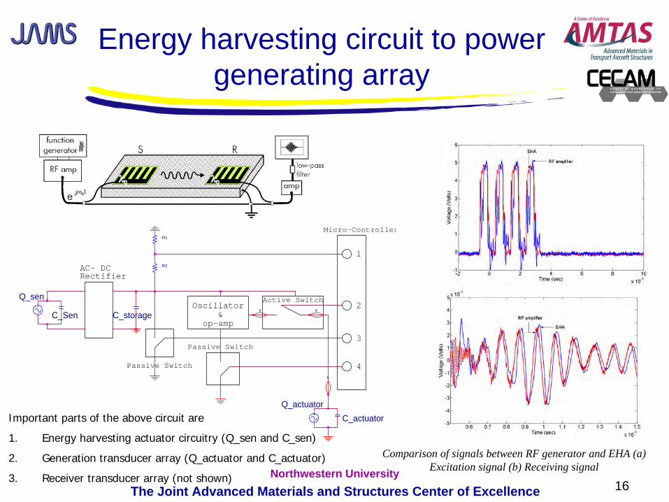
Q_actuatorC_actuatorImportant parts of the above circuit are
1. Energy harvesting actuator circuitry (Q_sen and C_sen)
2. Generation transducer array (Q_actuator and C_actuator)
3. Receiver transducer array (not shown)
Comparison of signals between RF generator and EHA (a) Excitation signal (b) Receiving signal
Energy harvesting circuit to power generating array
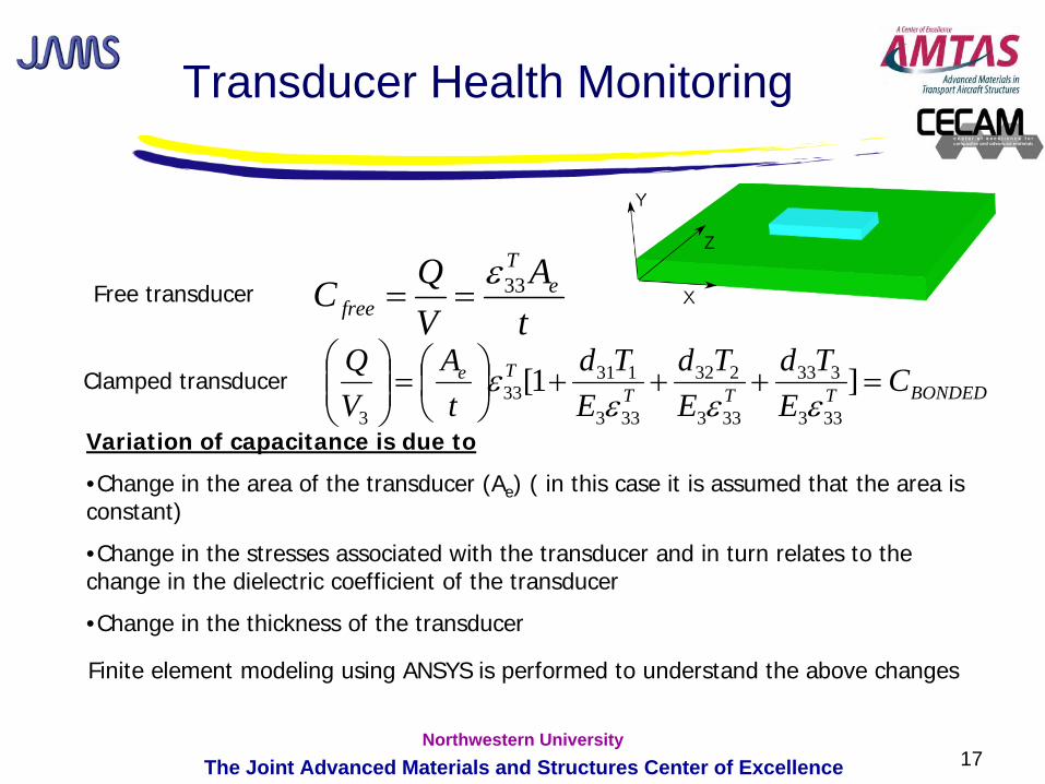
17The Joint Advanced Materials and Structures Center of ExcellenceNorthwestern University
BONDEDTTTTe C
ETd
ETd
ETd
tA
VQ
=+++⎟⎠⎞
⎜⎝⎛=⎟⎟
⎠
⎞⎜⎜⎝
⎛]1[
333
333
333
232
333
13133
3 εεεε
tA
VQC e
T
free33ε
==
Transducer Health Monitoring
Free transducer
Clamped transducer
Variation of capacitance is due to
•Change in the area of the transducer (Ae ) ( in this case it is assumed that the area is constant)
•Change in the stresses associated with the transducer and in turn relates to the change in the dielectric coefficient of the transducer
•Change in the thickness of the transducer
Finite element modeling using ANSYS is performed to understand the above changes
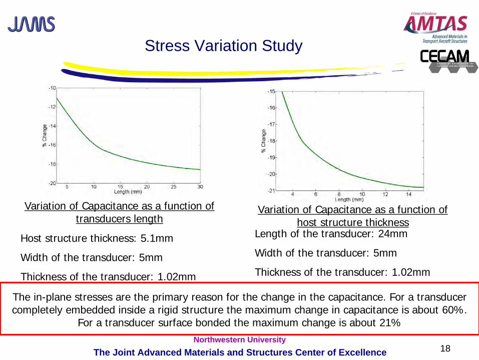
18The Joint Advanced Materials and Structures Center of ExcellenceNorthwestern University
The in-plane stresses are the primary reason for the change in the capacitance. For a transducer completely embedded inside a rigid structure the maximum change in capacitance is about 60%.
For a transducer surface bonded the maximum change is about 21%
Stress Variation Study
Variation of Capacitance as a function of transducers length
Variation of Capacitance as a function of host structure thickness
Host structure thickness: 5.1mm
Width of the transducer: 5mm
Thickness of the transducer: 1.02mm
Length of the transducer: 24mm
Width of the transducer: 5mm
Thickness of the transducer: 1.02mm
19The Joint Advanced Materials and Structures Center of ExcellenceNorthwestern University
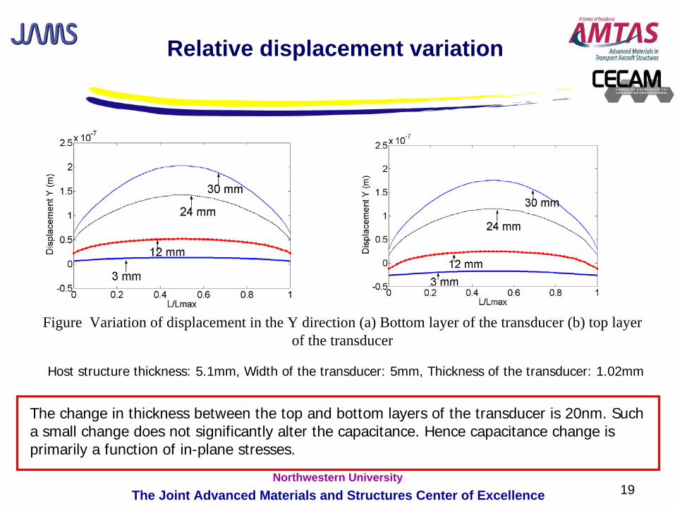
Relative displacement variation
Figure Variation of displacement in the Y direction (a) Bottom layer of the transducer (b) top layer of the transducer
Host structure thickness: 5.1mm, Width of the transducer: 5mm, Thickness of the transducer: 1.02mm
The change in thickness between the top and bottom layers of the transducer is 20nm. Such a small change does not significantly alter the capacitance. Hence capacitance change is primarily a function of in-plane stresses.
20The Joint Advanced Materials and Structures Center of ExcellenceNorthwestern University
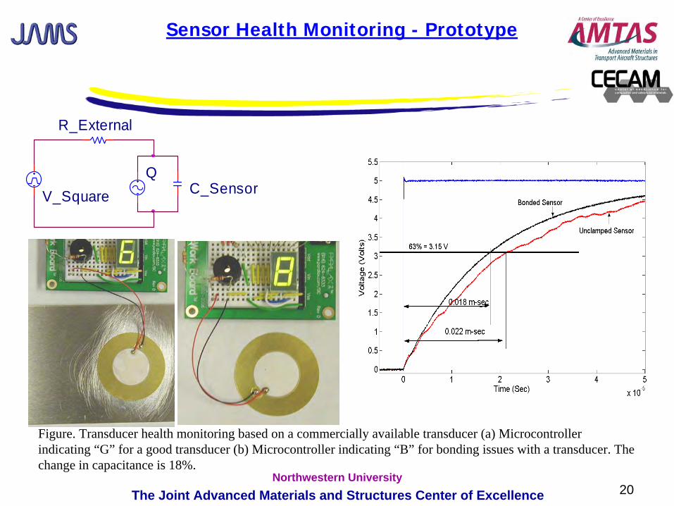
V_Square
R_External
QC_Sensor
Figure. Transducer health monitoring based on a commercially available transducer (a) Microcontroller indicating “G” for a good transducer (b) Microcontroller indicating “B” for bonding issues with a transducer. The change in capacitance is 18%.
Sensor Health Monitoring - Prototype
21The Joint Advanced Materials and Structures Center of ExcellenceNorthwestern University
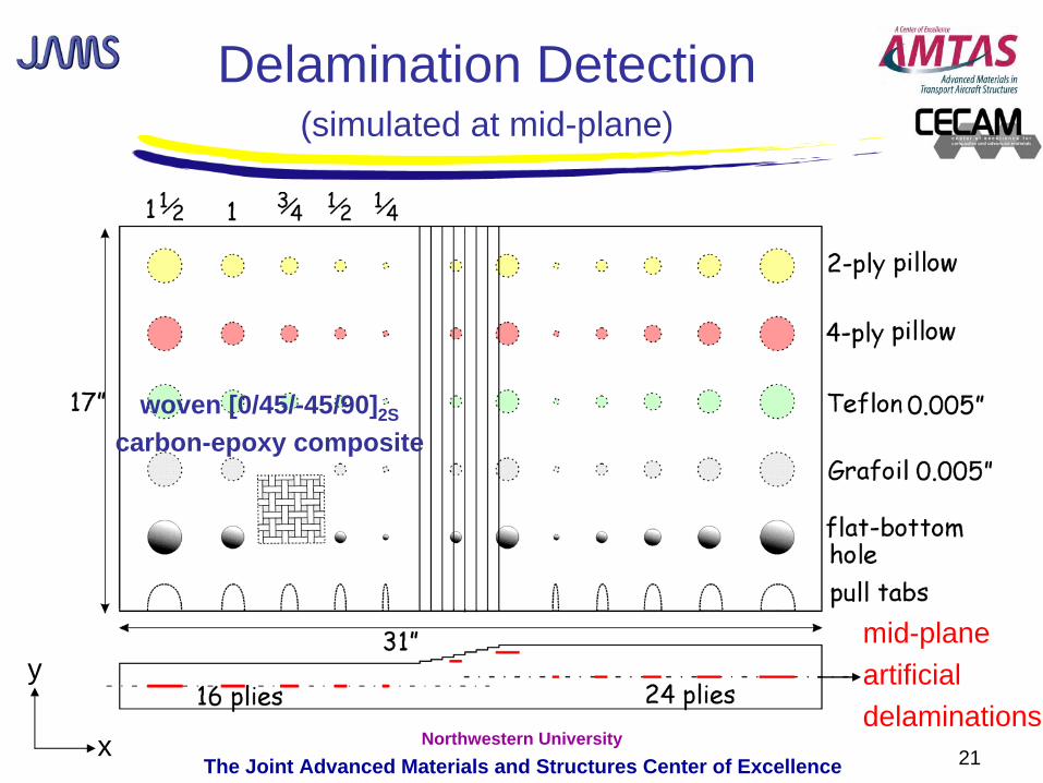
mid-planeartificialdelaminations
Delamination Detection(simulated at mid-plane)
y
x
woven [0/45/-45/90]2S
carbon-epoxy composite
22The Joint Advanced Materials and Structures Center of ExcellenceNorthwestern University
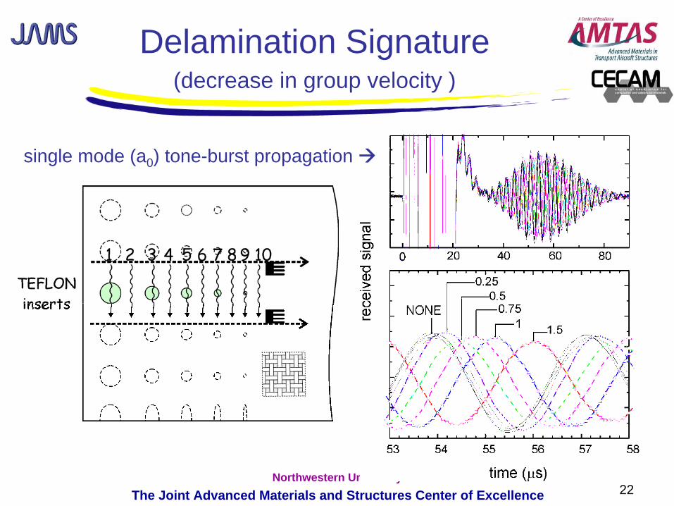
Delamination Signature(decrease in group velocity )
single mode (a0 ) tone-burst propagation
23The Joint Advanced Materials and Structures Center of ExcellenceNorthwestern University
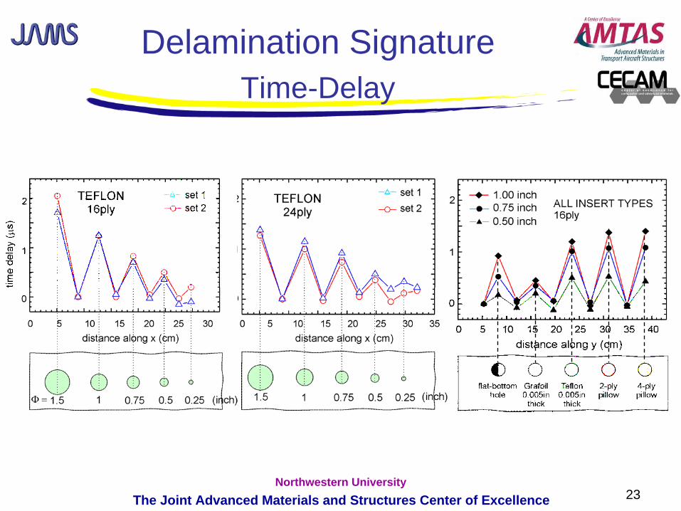
Delamination SignatureTime-Delay
24The Joint Advanced Materials and Structures Center of ExcellenceNorthwestern University
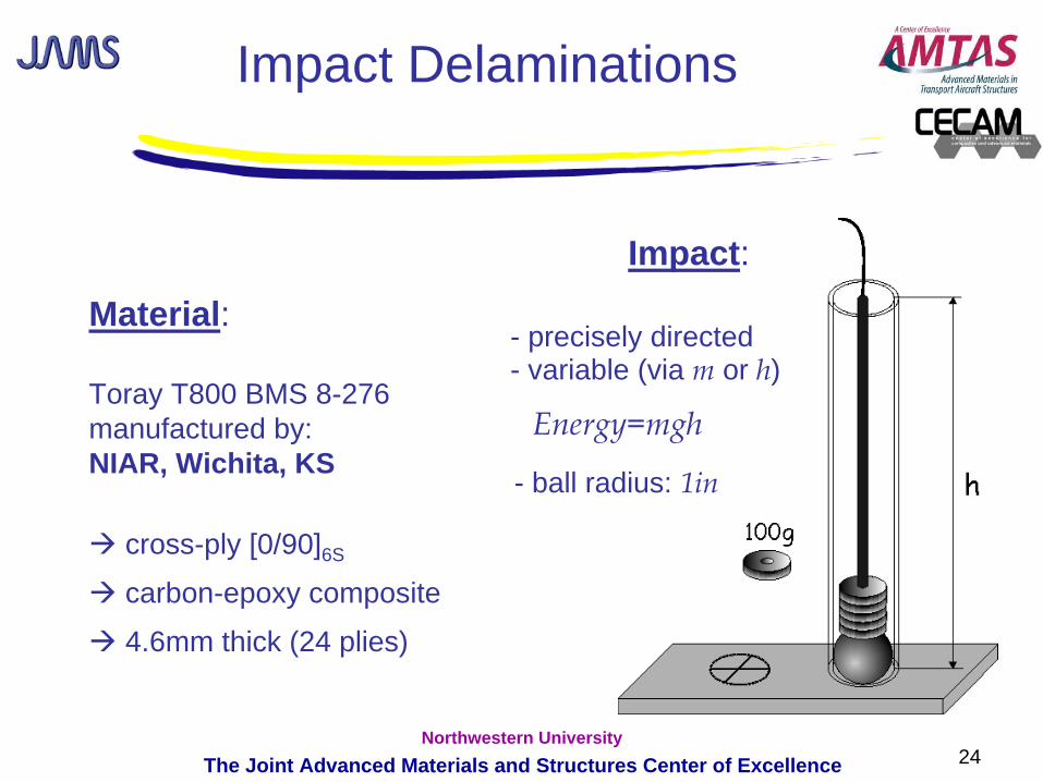
Impact Delaminations
Material:
Toray T800 BMS 8-276manufactured by:NIAR, Wichita, KS
cross-ply [0/90]6S
carbon-epoxy composite
4.6mm thick (24 plies)
Energy=mgh
- precisely directed- variable (via m
or h)
Impact:
- ball radius: 1in
25The Joint Advanced Materials and Structures Center of ExcellenceNorthwestern University
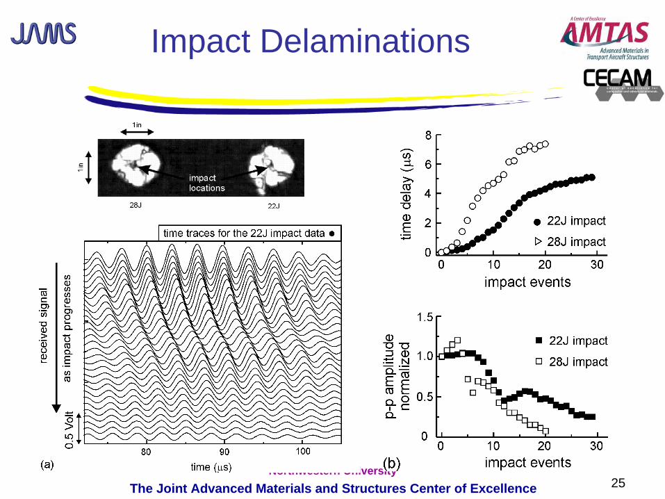
Impact Delaminations
26The Joint Advanced Materials and Structures Center of ExcellenceNorthwestern University
SHM of Composite Structures
• Monitor unanticipated events: A laminated composite aircraft panel suffers impact damage.
• Identify location of damage: Impact is identified by on-board PZT and FBG ultrasonic SHM
sensors which locate the point of impact.
• Image damaged region: Full-field NDI tool (Acoustocam) images the damage region (matrix
cracks…delaminations).
• Monitor damage growth: Modally-selective SHM sensors are installed around the damage
region to monitor further damage growth as the panel is subject to cyclic loading.
• Predict damage growth:Measured damage size is used in a probabilistic fatigue damage
model which estimates the remaining lifetime of the structure.
27The Joint Advanced Materials and Structures Center of ExcellenceNorthwestern University
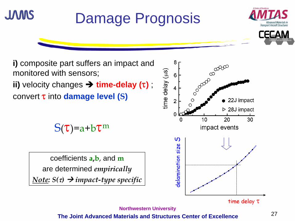
Damage Prognosis
S(τ)=a+bτm
i) composite part suffers an impact and is monitored with sensors; ii) velocity changes time-delay (τ) ; iii)convert τ into damage level (S)
coefficients a,b,
and mare determined empirically
Note: S(τ) impact-type specific

28The Joint Advanced Materials and Structures Center of ExcellenceNorthwestern University
Evaluated Failure Analysis Software for Composites:Alpha STAR’s Generalized Optimization and Analysis (GENOA)
software* is designed to evaluate the life, residual strength and damage/failure propagation in advanced materials and structures. GENOA performs progressive failure analysis (PFA) using finite element analysis (FEA) software (including commercial codes), full hierarchical modeling and materials engineering to determine:
- Material properties and property degradation - Damage and fracture initiation/progression- Failure mechanism contribution- Effects of manufacturing anomalies, including in-service damage, and environment including moisture and temperature- Component life and final failure load
Damage Prognosis
* ascgenoa.com
29The Joint Advanced Materials and Structures Center of ExcellenceNorthwestern University
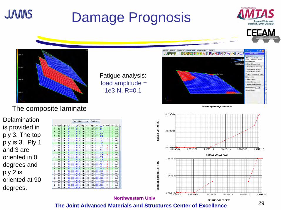
Fatigue analysis: load amplitude =
1e3 N, R=0.1
The composite laminate Delamination is provided in ply 3. The top ply is 3. Ply 1 and 3 are oriented in 0 degrees and ply 2 is oriented at 90 degrees.
Damage Prognosis
30The Joint Advanced Materials and Structures Center of ExcellenceNorthwestern University
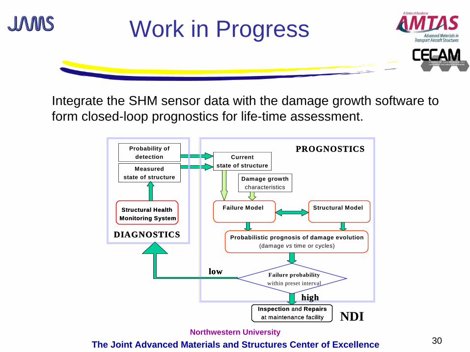
Work in Progress
Integrate the SHM sensor data with the damage growth software to form closed-loop prognostics for life-time assessment.
Currentstate of structure
Damage growthcharacteristics
Structural Health Monitoring System
Inspection and Repairsat maintenance facility
Probability ofdetection
Measuredstate of structure
Failure probabilitywithin preset interval
Failure Model Structural Model
Probabilistic prognosis of damage evolution(damage vs time or cycles)
high
DIAGNOSTICS
PROGNOSTICS
low
NDI
31The Joint Advanced Materials and Structures Center of ExcellenceNorthwestern University
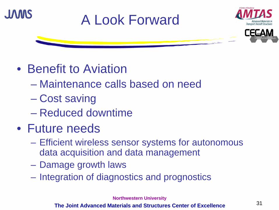
A Look Forward
• Benefit to Aviation– Maintenance calls based on need– Cost saving– Reduced downtime
• Future needs– Efficient wireless sensor systems for autonomous
data acquisition and data management– Damage growth laws– Integration of diagnostics and prognostics