Embed Size (px)
Citation preview
Proceedings of the International Association for Shell and Spatial Structures (IASS) Symposium 2009, Valencia Evolution and Trends in Design, Analysis and Construction of Shell and Spatial Structures
28 September – 2 October 2009, Universidad Politecnica de Valencia, Spain Alberto DOMINGO and Carlos LAZARO (eds.)
Structural design of the doubly curved Heysel canopy Kenny VERBEECK*, Laurent NEYa
*Project Engineer, Ney & Partners Structural Engineering s.a. Terhulpsesteenweg 181, B-1170 Brussels, Belgium
[email protected] a Directing Manager, Ney & Partners Structural Engineering s.a.
Abstract The design of the doubly curved canopy of the Heysel Tram Station by URA architects and Ney & Partners Structural Engineering aims to be a new icon for the Brussels, Belgium tramway terminus. The canopy, approximately 35m by 40m, covers the cross-roads where tramways and pedestrians meet. The shape of the shell and the positioning of the columns is a direct consequence of a balancing exercise between pedestrian comfort, integration of functionality, and minimal material usage. The architectural intention was specifically to present a singular free form canopy while reducing its visual complexity. The doubly curved canopy is conceived as a thin aluminium shell held by eight inclined slender steel columns. In order to reduce the number of visible elements, an extruded hollow aluminium cross-section for the shell is designed and developed. Using a single cross-section urges to normalize bending moments throughout the structure. This is achieved by developing the support-typology as a dialogue between engineering and architecture, and by manipulating the overall shell shape while assessing support positioning. Critical to the design was not fouling the tramway clearance, while keeping to the original architectural concepts. This paper will reconstruct in detail the design process explaining how a conceptual shell was developed into a doubly curved shell structure. During this process several techniques, such as scripting, 3D mesh calculations, were applied in order to render the complex geometry feasible while satisfying the architectural intentions and structural constraints. Keywords: Spherical shell, design process, aluminium, complex geometry, combinatorial optimization
1299
Proceedings of the International Association for Shell and Spatial Structures (IASS) Symposium 2009, Valencia Evolution and Trends in Design, Analysis and Construction of Shell and Spatial Structures
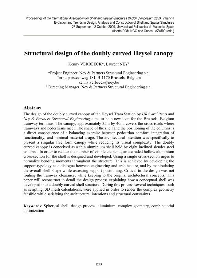
1. Design competition for tramway terminus In 2006 the Brussels Capital Region issued a design competition to re-design the tram station Heysel. The competition is part of an overall plan to re-design the main stations in the Brussels public transportation network. The competition brief demanded an icon that would mark the tramway terminus in the iconic Heysel exhibition park context. The Heysel exhibition park dates back to the Brussels International Exposition in 1935 and the Expo ’58. Some remarkable buildings, such as the Centenary halls, from the World’s Fair of 1935 shape the entire area. However, most people know the Heysel plains for the Atomium, built for the World’s Fair in 1958. The Atomium, a design by architect Andre Waterkeyn, represents the crystal structure of iron : a central cubic system of 9 spheres each 18m in diameter. Originally, it was a steel structure clad with aluminium panels intended only to last for the duration of the 1958 Exposition. Due to the building’s popularity the architectural sculpture remained after the Exposition and has become a landmark for the city of Brussels. During the renovations that began in 2003, the aluminium cladding was replaced by stainless steel elements.
Figure 1: Competition design image
1300

Proceedings of the International Association for Shell and Spatial Structures (IASS) Symposium 2009, Valencia Evolution and Trends in Design, Analysis and Construction of Shell and Spatial Structures
2. Competition design The competition design concept by URA architects proposes two object types on the site: 1) a series of small scale linear cantilevering canopies on the tramway platforms that give shelter and 2) a large canopy covering the central esplanade that marks the place. The central canopy is the attractor in the project. The thin shell entertains a subtle dialogue of form and material with the nearby Atomium, being alike and distinct. This paper will discuss the design of the central canopy, whereby the architecture is structure, and vice versa. The formal concept is that of a part of a large sphere, supported by slender columns. The spherical shape is a direct reference to the Atomium. By presenting a sphere part defined by a complex curve, the familiarity between icons is played down, and the new canopy reconnects to a contemporary architecture of free forms and surfaces.
3. Geometry The formal design of the canopy is of a geometrical nature: a quasi square grid of beam elements is superposed on the spherical shell. The grid is a scripted result of two rotational arrays of planes through the sphere centre that intersect the sphere. These intersections are per definition two sets of 2D arcs. The curves are discretized into a series of beam elements. This geometrical approach results in a continuous variation of element lengths and angles between elements. The contouring free form curve is initially an architecturally imposed constraint. By using scripting in McNeel Rhinoceros the used reference geometry file mathematically corresponds to the proposed geometry concept. This geometry definition was created by the structural engineer. The geometry file, consisting of reference lines, is then used to develop the design from an architectural and structural viewpoint.
Figure 2: Initial design concept (elevation, dimensions in m)
1301
Proceedings of the International Association for Shell and Spatial Structures (IASS) Symposium 2009, Valencia Evolution and Trends in Design, Analysis and Construction of Shell and Spatial Structures
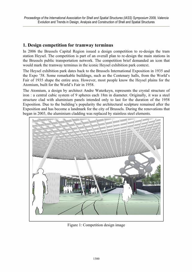
4. Aluminium extruded profile Choosing aluminium as a structural material is partly an architectural choice, partly a structural choice. Architecturally it references to the original material usage of the Atomium, while it structurally presents a favorable effect of reduced dead load of the structure. An advantage of aluminium is the relative ease – compared to steel – of extrusion as a process to create linear elements. A consequence of the extrusion process is the need and opportunity to create a custom mould, which comes with a non-neglectable cost. Therefore it was considered necessary to apply a single cross section to the entire project. Applying a singular section throughout the project implies that the single most solicited member determines the cross-section for the entire project. The less solicited members are thus overdimensioned. Hence, one can design for resistance instead of for deformation. For esthetic and structural reasons it was decided not to assemble by welding. Extruding the aluminium profiles allows creating cavities in the profile cross-section. This reduces the weight of the profile, while offering an opportunity to integrate to connection detailing inside. To reduce the number of bolts in the project, the internal connecting pieces are glued to the aluminium.
Figure 3: Custom hollow aluminium cross-section
1302
Proceedings of the International Association for Shell and Spatial Structures (IASS) Symposium 2009, Valencia Evolution and Trends in Design, Analysis and Construction of Shell and Spatial Structures
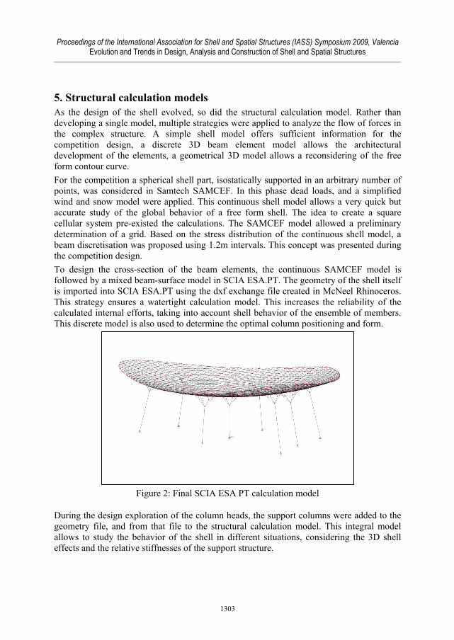
5. Structural calculation models As the design of the shell evolved, so did the structural calculation model. Rather than developing a single model, multiple strategies were applied to analyze the flow of forces in the complex structure. A simple shell model offers sufficient information for the competition design, a discrete 3D beam element model allows the architectural development of the elements, a geometrical 3D model allows a reconsidering of the free form contour curve. For the competition a spherical shell part, isostatically supported in an arbitrary number of points, was considered in Samtech SAMCEF. In this phase dead loads, and a simplified wind and snow model were applied. This continuous shell model allows a very quick but accurate study of the global behavior of a free form shell. The idea to create a square cellular system pre-existed the calculations. The SAMCEF model allowed a preliminary determination of a grid. Based on the stress distribution of the continuous shell model, a beam discretisation was proposed using 1.2m intervals. This concept was presented during the competition design. To design the cross-section of the beam elements, the continuous SAMCEF model is followed by a mixed beam-surface model in SCIA ESA.PT. The geometry of the shell itself is imported into SCIA ESA.PT using the dxf exchange file created in McNeel Rhinoceros. This strategy ensures a watertight calculation model. This increases the reliability of the calculated internal efforts, taking into account shell behavior of the ensemble of members. This discrete model is also used to determine the optimal column positioning and form.
Figure 2: Final SCIA ESA PT calculation model
During the design exploration of the column heads, the support columns were added to the geometry file, and from that file to the structural calculation model. This integral model allows to study the behavior of the shell in different situations, considering the 3D shell effects and the relative stiffnesses of the support structure.
1303
Proceedings of the International Association for Shell and Spatial Structures (IASS) Symposium 2009, Valencia Evolution and Trends in Design, Analysis and Construction of Shell and Spatial Structures
This integral model is sufficiently complete to draw all necessary information for the detailed design of the joints. This model was entirely rebuilt after changing the shape of the contouring curve to validate the already detail designs.
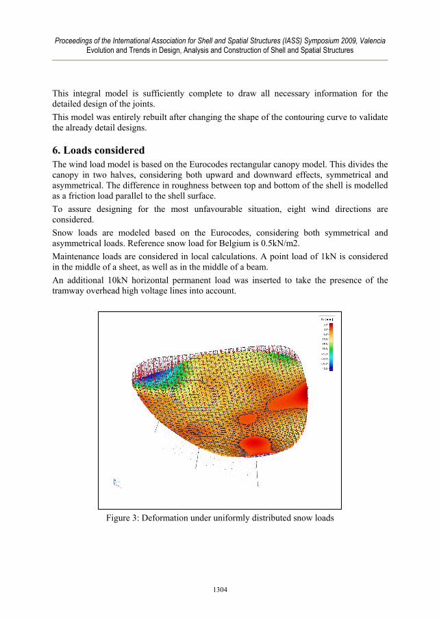
6. Loads considered The wind load model is based on the Eurocodes rectangular canopy model. This divides the canopy in two halves, considering both upward and downward effects, symmetrical and asymmetrical. The difference in roughness between top and bottom of the shell is modelled as a friction load parallel to the shell surface. To assure designing for the most unfavourable situation, eight wind directions are considered. Snow loads are modeled based on the Eurocodes, considering both symmetrical and asymmetrical loads. Reference snow load for Belgium is 0.5kN/m2. Maintenance loads are considered in local calculations. A point load of 1kN is considered in the middle of a sheet, as well as in the middle of a beam. An additional 10kN horizontal permanent load was inserted to take the presence of the tramway overhead high voltage lines into account.
Figure 3: Deformation under uniformly distributed snow loads
1304
Proceedings of the International Association for Shell and Spatial Structures (IASS) Symposium 2009, Valencia Evolution and Trends in Design, Analysis and Construction of Shell and Spatial Structures
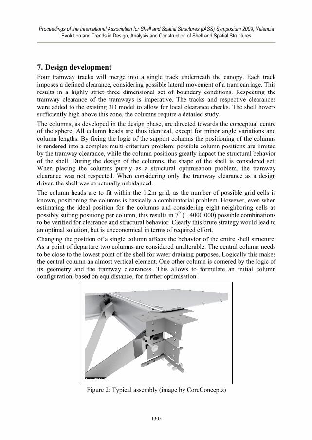
7. Design development Four tramway tracks will merge into a single track underneath the canopy. Each track imposes a defined clearance, considering possible lateral movement of a tram carriage. This results in a highly strict three dimensional set of boundary conditions. Respecting the tramway clearance of the tramways is imperative. The tracks and respective clearances were added to the existing 3D model to allow for local clearance checks. The shell hovers sufficiently high above this zone, the columns require a detailed study. The columns, as developed in the design phase, are directed towards the conceptual centre of the sphere. All column heads are thus identical, except for minor angle variations and column lengths. By fixing the logic of the support columns the positioning of the columns is rendered into a complex multi-criterium problem: possible column positions are limited by the tramway clearance, while the column positions greatly impact the structural behavior of the shell. During the design of the columns, the shape of the shell is considered set. When placing the columns purely as a structural optimisation problem, the tramway clearance was not respected. When considering only the tramway clearance as a design driver, the shell was structurally unbalanced. The column heads are to fit within the 1.2m grid, as the number of possible grid cells is known, positioning the columns is basically a combinatorial problem. However, even when estimating the ideal position for the columns and considering eight neighboring cells as possibly suiting positiong per column, this results in 79 (+ 4000 000) possible combinations to be verified for clearance and structural behavior. Clearly this brute strategy would lead to an optimal solution, but is uneconomical in terms of required effort. Changing the position of a single column affects the behavior of the entire shell structure. As a point of departure two columns are considered unalterable. The central column needs to be close to the lowest point of the shell for water draining purposes. Logically this makes the central column an almost vertical element. One other column is cornered by the logic of its geometry and the tramway clearances. This allows to formulate an initial column configuration, based on equidistance, for further optimisation.
Figure 2: Typical assembly (image by CoreConceptz)
1305
Proceedings of the International Association for Shell and Spatial Structures (IASS) Symposium 2009, Valencia Evolution and Trends in Design, Analysis and Construction of Shell and Spatial Structures
The shell was optimised for both a spatial and a structural criterion in an iterative process between the modelling environment and the structural calculation environment. The spatial criterion is a straightforward “conflict” or “no conflict” between columns and tramway clearances. The structural criterion was the minimization of maximal bending moments. The technique applied is manual and straightforward. In each iteration a column is moved to an adjacent cell without fouling the tramway clearance, for this configuration the maximal bending moments in the shell elements are then analyzed. The area presenting the maximal or minimal bending moments is then affected by displacing a nearby column. Both situations are relevant in order to equalize the internal efforts envelope throughout the shell (considering the various load cases and combinations). In parallel with finding an optimal configuration of support columns, the column head typology also affects the global bending diagram of the shell. During the competition circular hollow tubes were considered. Increasing the number of beam curves affected by the columns reduces in itself the maximal bending moments in the shell elements. In the final design each column is treelike shaped and affects 4 beam curves in each direction. The architectural concept of the columns is determined by steel fabrication: the tree shape consists of four bent steel sheets.
8. Changing the shape After developing the global and detailed design of the shell and its support columns, the client decided to enlarge the canopy to create a no-go-zone underneath the canopy in order to avoid people traversing the rail switches. During the competition the contour had been an architectural decision, which was basis for the structural design of the canopy. To redesign the global shape of the canopy within a short time frame while maintaining the existing detail design, a different approach than applied so far is required. The iterative process between geometry modification and calculation model is exact, but too time consuming (in terms of constructing the calculation model) when considering the shape of the canopy as a variable parameter. To determine a new shape (the spherical grid remained as formal concept) a geometrical strategy was adopted. For a given contour and virtual support locations a Rhinoceros script estimates the contributing area per support. The contributing area is considered proportional to the maximal bending moments. Iteratively this contour and support positioning is then modified to maximize total surface of the canopy while aiming to equalize the contributing areas to the supports. A short optimization followed when considering the actual grid and tree shape of the support columns. This geometrical approach proved to combine speed and accuracy to re-design the canopy’s contour. The area covered by the canopy was enlarged by over 10%, without requiring any changes in the detail design (cross-section, node assembly, support columns, etc).
1306
Proceedings of the International Association for Shell and Spatial Structures (IASS) Symposium 2009, Valencia Evolution and Trends in Design, Analysis and Construction of Shell and Spatial Structures
9. Architecture in structural design The design process of the Heysel canopy is multi-threaded. It is influenced by early design decisions (the use of an extruded aluminium profile), by geometrical constraints (the tramway clearances), the architectural geometrical concept (spherical form logic). For complex projects it is tempting to create structural calculation models that incorporate each detail of the structure and allow a very precise verification inside that complete virtual structure. It has proven for the Heysel canopy that this approach does not allow for the structural design to keep up with the architectural design. It does not allow to adapt to the changing of parameters. Even what is considered set (the global shape) became a variable. To deal with this flexibility, throughout the project several structural design strategies (equivalent to an architectural sketch) were applied. These quick calculations allowed to abstract and develop for different aspects without losing the global idea. This global idea was represented in a 3D reference model that functioned as the backbone of the project. But after considering the global shape of the canopy as a parameter, also this reference model was replaced and rebuilt, based on a quick calculation model The design of the doubly curved canopy of the Heysel Tram Station is collaborative effort by URA architects and Ney & Partners Structural Engineering. To deal with complexity a flexible attitude is required from both engineer and architect. In order to create a visually simple, yet complex object such as the thin double curved Heysel canopy, it was necessary that the engineer would consider the architectural of each design step, and the architect the structural. When the complexity is intended to be perceived as evident, thinking of architecture and structure as separate aspects, would be dysfunctional.
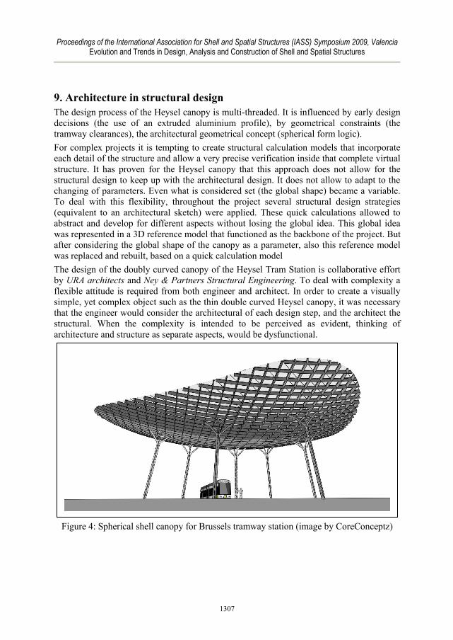
Figure 4: Spherical shell canopy for Brussels tramway station (image by CoreConceptz)
1307