Embed Size (px)
Citation preview
Structural Design of CLT Stability Systems
Toby Hodsdon | Associate | Arup
Wood Solutions Seminar – 16 May 2019

Introduction
1. Introduction
• Example projects
• Basic challenges of stability for timber buildings
• Structural testing and behaviour
2. Bracing walls and cores
3. Diaphragms
4. Modelling
5. Design
6. Further Information

Project Examples
Aveo Norwest
10 Stories
MacArthur Gardens
6, 7, 8 Stories

Project ExamplesForte
10 Stories
Oakleigh Childcare Centre
1 Storey

Stability Systems
Credit: Wood Solutions
Load to bracing walls
Diaphragm transfer

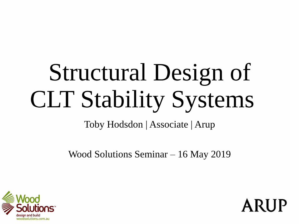
Challenges of Stability
Lightweight - hold down and uplift is important
One-way spanning floors - affects distribution of
gravity loads
Connections govern behaviour of shear walls -
cannot use conventional analysis methods
Diaphragms not always rigid - affects distribution of
lateral load
Presence and location of vertical joints in walls
matter - manufacturing and transportation limits may
affect design
Panelised design and connection details affect
buildability and cycle time - critical to the success of
a CLT project
Also have shortening effects, floor crushing and
potential frame elongation to consider
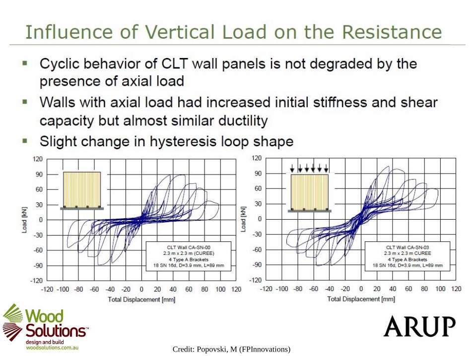
Challenges of Stability
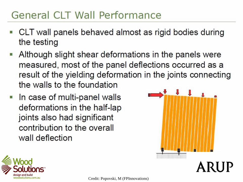
Credit: Popovski, M (FPInnovations)

Credit: Popovski, M (FPInnovations)
Credit: Popovski, M (FPInnovations)

Credit: Popovski, M (FPInnovations)

Credit: Popovski, M (FPInnovations)

C-shaped Cores
Credit: Brown, J. (University of Canterbury)

Design of bracing walls and cores
Overturning
Stiffness
Compound sections
Other considerations

Bracing walls
Establish loads at bottom of walls, and at each floor level (above and below slab)
Credit: ProHolz guide

Bracing walls Check uplift in hold-down adopting suitable lever arm
Check cross-grain compression
Credit: ProHolz guide, Reynolds et. al

Bracing walls
Calculate deflections based on:
• Shear and flexure of panel
• Translation and rotation due to
connections
Also consider:
• Rotation due to cross-grain
compression
• Rolling shear of floor
• Joint slip if panels have vertical
lap joints

Bracing walls
Check connections:
• Shear connections at slab connections
• Vertical joints

Mass timber cores
Similar checks to bracing walls, however:
• Low gravity loads mean high uplifts
• Practical aspects and spatial limitations of
hold-down connections
• Shear transfer at joins must be examined, or
design as discreet elements
• Ensure walls restrained by floors on all
sides
Also consider:
• Fire performance
• Acoustics
• Vibration
• Coordination with lift manufacturers
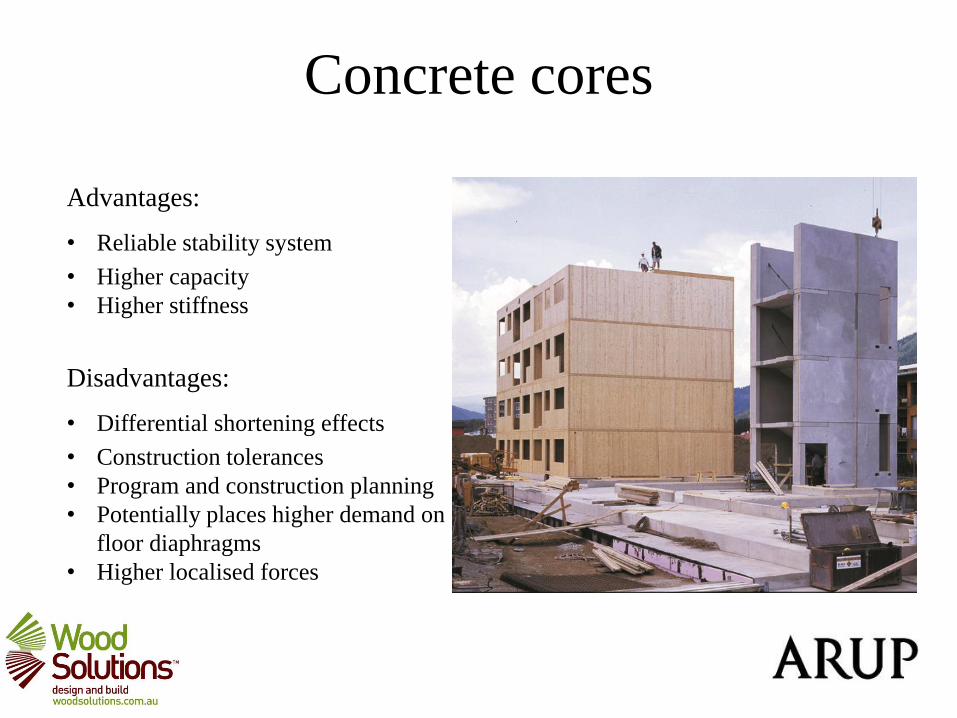
Concrete cores
Advantages:
• Reliable stability system
• Higher capacity
• Higher stiffness
Disadvantages:
• Differential shortening effects
• Construction tolerances
• Program and construction planning
• Potentially places higher demand on
floor diaphragms
• Higher localised forces

Bracing wall modelling
Three approaches:
1. Use spreadsheet to build up horizontal load-take-down and calculate deflection
components
2. Stick and spring models
3. Finite element with gap elements, tension only elements and springs

Modelling issues
• Elements orthotropic, and effective bending thickness does not match actual thickness
• Have to incorporate connection stiffnesses based on supplier data
• Stiffnesses of HD bolts may need to be halved if continue through floors
• Set up model so forces can be extracted for connection design (more important than element design)
• Wall response is highly non-linear if modelled accurately and takes a long time to analyse
• FE good to explore shear stress over plate, explore penetrations etc. but takes much more effort
• Due to the importance of connections, highly iterative

Rules of Thumb
G = 1kPa (NLB) or 2kPa (LB) - approx
Lever arm = Lwall - 1m
Floor rigid if span/depth < 2
Load in wall based on trib width if flexible diaphragm
Stiffness is proportional to L1.5
Friction is ~0.3 (varies 0.2 - 0.4)
Max uplift ~40 kN per fastener

Mass timber diaphragms

Mass timber diaphragms
Purpose of diaphragms transfer wind and seismic loads to LLRS
Also tie columns, beams together
Can be timber/concrete composites, ply sheeting, SIPS or mass timber
Comprise plate elements with chords, collectors and connections
Typically designed using the girder analogy
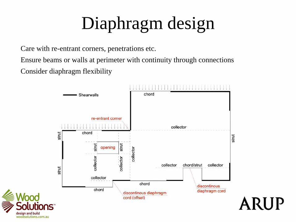
Diaphragm design
Care with re-entrant corners, penetrations etc.
Ensure beams or walls at perimeter with continuity through connections
Consider diaphragm flexibility

Diaphragm design
Flexible if diaphragm deflection > 2*inter-storey drift
If flexible - loads distributed according to tributary width;
if rigid, loads distributed according to wall stiffness.
In reality, likely to be between, and an envelope of forces could be adopted
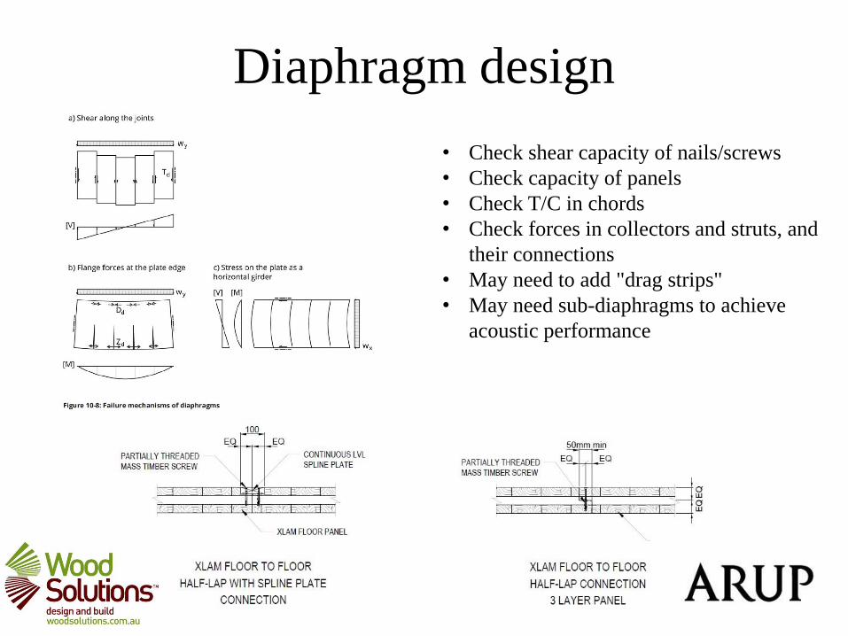
Diaphragm design
• Check shear capacity of nails/screws
• Check capacity of panels
• Check T/C in chords
• Check forces in collectors and struts, and
their connections
• May need to add "drag strips"
• May need sub-diaphragms to achieve
acoustic performance

Diaphragm modelling
Four approaches:
1. Envelope of forces based on flexible or rigid
2. Use girder analogy for beams and springs for walls if span / depth > 2
3. Truss analogy for flexible diaphragms (usually joists)
4. Finite element modelling, with connection stiffness modelled

Design Approach
1. Establish overall stability loads.
2. Frame up floors with repetition. Determine span direction and gravity load path, review available length of walls in each direction and consider alternating floor span direction. Decide if platform construction and examine cross-grain compression.
3. Compare lateral loads with gravity loads - how far over? Are HD forces reasonable?
4. Decide concrete core vs. bracing walls or alternatives
5. Review implications for foundation/transfer structure
6. If bracing walls, commence more detailed assessments of wall stiffness, connection designs and diaphragm performance.
7. Review assumptions with acoustic and fire consultants early.

Optimisation
Optimisation of the no. of walls, connection details, and no. fasteners.
Other criteria likely to govern wall and floor thicknesses
• Configure building to make best use of gravity loads
• Increase level of certainty around diaphragm flexibility and load paths
• Adopt screw details wherever possible, whilst not undermining ductility
• Consult with supplier to select best value connectors

Alternatives
• Consider epoxy-bonded rods and plates with dowels for the most heavily loaded tie-downs
• Post-tensioning of LVL walls (e.g. Preslam solution)
• Adopt braced or moment frames at the perimeter of the building
• Tie party walls together as large C-shaped cores

Further Information
• Wood Solutions guide 35 – Diaphragms
• ProHolz guide, Cross-Laminated Timber Structural Design (EU)
• FPInnovations guides (US/Canada)
• TRADA guides (UK)
Forthcoming:
• Wood Solutions CLT Design Example
• Wood Solutions Structural Engineers Guide
• BRANZ guide

Acknowledgements