Embed Size (px)
Citation preview
May 30, 2009 Page 1 1
STRUCTURAL DESIGN, ESTIMATING & QUALIFYING
Save $Millions by asking for order in time it takes for a coffee break!
C:\WINBUILDIT\ BUILHELP_3.DOC or PDF May 30, 2009
By Don Suverkrop, P.E. and Ron Suverkrop, Architectural Designer
CONTENTSWINBUILDIT
SEARCH CHAPTER PAGE DVDTEXT TITLE NUMBER minutes
AAA1 WINBUILDIT INTRODUCTION PAGE 2 17 minAAA2 INSTALLATION PAGE 3AAA3 A WALK THROUGH PAGE 4AAA4 “DEAD DOGS” CAN KILL YOU! PAGE 5AAA5 GRAB THE BULL BY THE HORNS PAGE 6AAA6 NAVIGATING WINBUILDIT “A” PAGE 9AAA7 WINBUILDIT “A” EXPLAINED PAGE 10 35 minAAA8 WINBUILDIT “A” MARKETING PAGE 11
DESCRIPTION FILES:FFF06 SHAPE HELP PAGE 12 35 minFFF72 SETBACKS - Form72 PAGE 16 17 minFFF07 DETAILS - Form7 - PAGE 18 33 minFFF65 WIND - Form65 - PAGE 20 5 minFFF05 SEISMIC - Form5 - PAGE 22 5 minFFF34 FLOOR AND ROOF JOISTS - Form34 PAGE 24 9 minFFF21 FILE HANDLING – Form21 PAGE 27FFF32 BEAM LOAD PLANNING PAGE 29FFF33 ELEVATOR SHAFTS PAGE 31FFF09 COMPUTE and ANALYZE - Form9 PAGE 33FFF17 BUSINESS PLAN OPTIMIZATION PAGE 35FFF38 BUSINESS PLAN MULTI USAGE PAGE 36
COST FILES:FFF23 COSTS_1, SUBSTRUCTURE, SHELL PAGE 38FFF14 COSTS_2, EXTERIOR, DOORS, ROOFFFF13 COSTS_3, PARTITIONS, DOORSFFF15 COSTS-4, ELEVATORS, PLUMBINGFFF18 COSTS-4.5, PLUMBINGFFF19 COSTS_4.8, HEAT, COOLING, PIPINGFFF16 COSTS 5, MISCFFF17 COSTS 6, BUSINESS PLAN
FFF03 FINANCIAL ANALYSIS PAGE 39 35 minFFFB “B” IRR CALCULATOR PAGE 40FFFC "C" COMMERCIAL CALCULATOR PAGE 41FFFD "D" CONSTRUCTION IRR CALCULATOR PAGE 45FFFE "E" MULTI-USAGE CALCULATOR PAGE 46FFFF "F" OILFIELD FINANCIAL ANALYSIS PAGE 50FFFG "G" - MINING & BUSINESS CALC. PAGE 52APPEN APPENDIX PAGE 54
Tel 661 871 2168 - Fax 661 871 1798 - Cell 661 809 4764 www.winbuildit.comCREATIVE ENGINEERING USA3513 Century DriveBakersfield, CA 93306 1238
May 30, 2009 Page 2 2
AAA1 WINBUILDIT INTRODUCTION 17 MIN
THE BILLION DOLLAR PROBLEM
Clients, Architects, Engineers, Contractors ("A/E/C"), and Equipment Dealers wasteBILLIONS OF DOLLARS on unsuccessful proposals and, bids. A sea of waste created by anemphasis on “running the clock”, poor decisions, misdirected technology for qualificationpurposes and an inability to optimize in real-time. It is little wonder that the FEAR of wastingmoney on poorly contrived projects makes putting money under the mattress a preferredalternative.
and THE FREEBIE SOLUTION
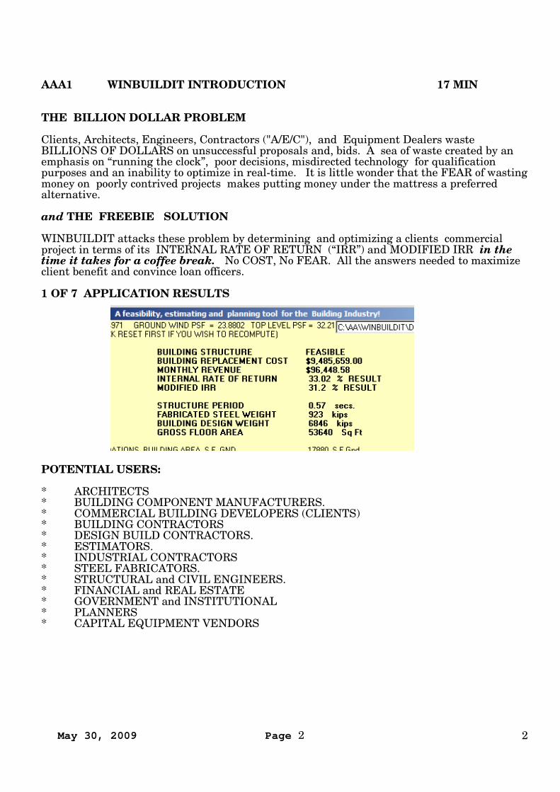
WINBUILDIT attacks these problem by determining and optimizing a clients commercialproject in terms of its INTERNAL RATE OF RETURN (“IRR”) and MODIFIED IRR in thetime it takes for a coffee break. No COST, No FEAR. All the answers needed to maximizeclient benefit and convince loan officers.
1 OF 7 APPLICATION RESULTS
POTENTIAL USERS:
* ARCHITECTS* BUILDING COMPONENT MANUFACTURERS.* COMMERCIAL BUILDING DEVELOPERS (CLIENTS)* BUILDING CONTRACTORS* DESIGN BUILD CONTRACTORS.* ESTIMATORS.* INDUSTRIAL CONTRACTORS* STEEL FABRICATORS.* STRUCTURAL and CIVIL ENGINEERS.* FINANCIAL and REAL ESTATE* GOVERNMENT and INSTITUTIONAL* PLANNERS* CAPITAL EQUIPMENT VENDORS

May 30, 2009 Page 3 3
AAA2 INSTALLATION
Delete any existing WINBUILDIT folder.
Copy \WINBUILDIT folder from CD to C: drive
TO OPEN DEMO PROGRAM: Click | Start My Computer | Local Disk (C:) | Explore |WINBUILDIT | AAD_WINBUILDIT | Open |
TO OPEN LICENSED VERSION, Open version prefixed with AAL rather than AAD.
Easy to use shortcuts for accessing Programs are made by clicking onto a blank spot on thedesktop | New | Shortcut | then enter Program name:(C:\WINBUILDIT\AAD_WINBUILDIT.EXE)
May 30, 2009 Page 4 4
AAA3 A WALK THROUGH
WINBUILDIT’S original purpose was the optimization and economic measurement ofcommercial building design in terms of its INTERNAL RATE OF RETURN and MODIFIEDINTERNAL RATE OF RETURN result. At Form3 this direction is taken by clicking on to thegreen label under the red START HERE “A” near the upper left of the form.
Calculators B to G are adapted INTERNAL RATE OF RETURN and MODIFIED INTERNALRATE OF RETURN calculators that borrow code from “A” . From simple data entry and clickcompute or apply the final results are displayed. No knowledge or learning of the underlyingmathematics or use of pocket calculators is required.
| IRR CALCULATOR “B” | displays results from 5 simple data entries. A Kenworth TruckDealer used it to predict availability of financing for a used truck. A real estate broker usedit to evaluate a transaction. Calculator assumes all cash flows are evenly distributed. Accessis made by entering the requested directly on Form3 and then clicking | APPLY – 8 |
| “C” COMMERCIAL INTERNAL RATE OF RETURN – 11 | This universal calculator isaccessed by clicking on to the command button of that name located near lower left of Form3.Individual inflow or outflow cash flows can by assigned to any month or year for a period up to100 years. Automatic repeat with inflation, deflation and capital cost give flexibility andspeed to an otherwise very complex calculation.
| “D” CONSTRUCTION INTERNAL RATE OF RETURN CALCULATOR – 12 | is accessed byclicking onto the command button of that name located near lower left of Form3. Thiscalculator is a simplification of “A” where both the | 11 - GROSS FLOOR AREA FT2 | and |107 - $/SF | are already known.
| “E” MULTI USAGE INTERNAL RATE OF RETURN CALCULATOR – 13 | is accessed byclicking onto the command button of that name located in lower left quadrant of the form. Thisform is similar to “D” except allows up to 8 multi usages such as for retail, office, hotel etcuses.
| “F” OILFIELD – 15 | is accessed by first clicking onto the label of that name located nearbottom center of form and then clicking onto | OILFIELD – 19 | located near top center ofForm36. This calculator enables evaluation of complex oilfield exploration and productionopportunities.
| “G” MINING / GENERAL BUSINESS | is accessed by clicking onto the label of that namenear bottom right of form3 and then clicking onto command button |MINING / BUSINESS –21 | located in upper right of Form36. This form is an adaptation of “F” but enables dataentry in universal units acceptable for any project.
The purpose of these forms is to reduce any business plan to its INTERNAL RATE OFRETURN and/or MODIFIED INTERNAL RATE OF RETURN so that an intelligent decisioncan be made to proceed, qualify or obtain credit for its execution.
May 30, 2009 Page 5 5
AAA4 “DEAD DOGS” CAN KILL YOU!
Industry spends $Billions in the planning and estimating of specially engineered projects .Those supplying this market waste $Billions more chasing the same market. Since mostprojects are never built and for vendors making offers in the crowded market place the successor "hits" ratio usually rates no better than a dismal "F". If there are 10 bidders on a projectthat means that 90% of bidders are spinning their wheels and that becomes 100% when theowner decides "its more money than I planned on spending" , "I can't get financing" , "themarket has changed" or etc.
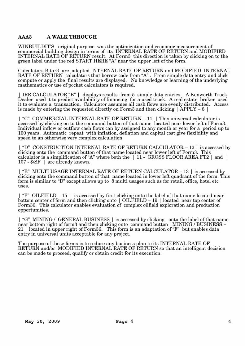
Bringing reason to this morass | ESTIMATOR | (part of the WINBELT collection) works topredict qualification at the very beginning rather than weeks, months and even years later.Here’s how:
1) Near upper left make 9 entriesunder INPUT DATA – 1.
2) Then based on previous beltconveyor projects having a similarcombination of goods and services, but ofdifferent size and length, ESTIMATORuses statistical techniques to compute anestimate seen under ESTIMATEDINSTALLED PRICE near lower right.See note (1) below.
3) This estimate may in itself qualifythe project.
4) But if not, using the sameestimate within the INTERNAL RATEOF RETURN ("IRR") "B" CALCULATORa “Return on Investment” computation ismade suitable for sophisticated financialanalysis requirements.
5) In minutes you and the clientBOTH know what the qualification is!
(1) AAL_ESTIMATE - Computes prices of belt conveyors using an adaptation of AIMEmethods. Programs available from:
661 871 2168 – Fax 661 871 1798 www.beltconveyor.comCREATIVE ENGINEERING USA3513 Century Dr.Bakersfield , Ca 93306
May 30, 2009 Page 6 6
AAA5 GRAB THE BULL BY THE HORNS
INVESTOR FEAR OF LOOSING MONEY, resulting from the current economic, financial,credit and confidence crisis chases customers away in droves. The cost of resultinginefficiencies and business lost is in the $Billions. Meanwhile order books are running onempty.
BANKER FEAR OF LOOSING MONEY reflects a history of poor loans. Given thedivergence in feasibility methods (Mc Graw Hill counts 201) and questionable results (TheWall Street Journal refers to widespread “betting”) this is not an unfounded fear.
WINBUILDIT TRUMPS THESE FEARS SIMPLY BY ENABLING SALES PERSONS ANDOTHER PROGRAM USERS TO SEEK, IDENTIFY, INITIATE AND QUALIFYOPPORTUNITIES USING RECOGNIZED FINANCIAL ANALYTICAL TECHNIQUES FORFREE IN THE TIME IT TAKES FOR A COFFEE BREAK!
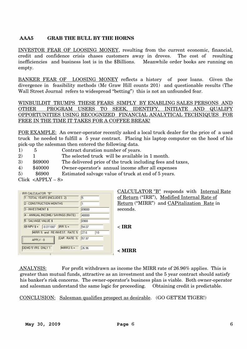
FOR EXAMPLE: An owner-operator recently asked a local truck dealer for the price of a usedtruck he needed to fulfill a 5 year contract. Placing his laptop computer on the hood of hispick-up the salesman then entered the following data.1) 5 Contract duration number of years.2) 1 The selected truck will be available in 1 month.3) $69000 The delivered price of the truck including fees and taxes,4) $40000 Owner-operator’s annual income after all expenses5) $6900 Estimated salvage value of truck at end of 5 years.Click <APPLY – 8>
CALCULATOR "B" responds with Internal Rateof Return (“IRR”), Modified Internal Rate ofReturn (“MIRR”) and CAPitalization Rate inseconds.
< IRR
< MIRR
ANALYSIS: For profit withdrawn as income the MIRR rate of 26.96% applies. This isgreater than mutual funds, attractive as an investment and the 5 year contract should satisfyhis banker’s risk concerns. The owner-operator’s business plan is viable. Both owner-operatorand salesman understand the same logic for proceeding. Obtaining credit is predictable.
CONCLUSION: Salesman qualifies prospect as desirable. (GO GET’EM TIGER!)
May 30, 2009 Page 7 7
“GRAB THE BULL BY THE HORNS” AND INITIATE “COLD TURKEY” SELLINGSTRATEGIES In 1992 Creative Engineering was ordered to make a market survey for anexpensive mining machine. The decision was made that in order to distinguish betweenvarious $Million dollar price tags and value of the machine as a profit producer a computerprogram was needed that could quickly do this before being “shown the door”. The programturned out to be HAULPLAN. Used during a “cold turkey” foray to 12 Northern Nevada GoldMines the offer of a “free mine plan feasibility study” gained entry past guards to 11 successfulcalls on mine managers averaging 3 hours each. 2 likely prospects were identified but whatthe mine managers quickly discovered was they could also real-time optimize a mine’s plan toan INTERNAL RATE OF RETURN result. This means optimizing towards a greater share-holder value. Or, as one mine engineer put it; “The Program did in 2 seconds what just tookme 2 months”. The foray definitely proved worthwhile and suggested a plan for marketingother commercial products as well.
WINBUILDIT was written to address this wider market. In addition to Internal Rate ofReturn (“IRR”), Modified Internal Rate of Return (“MIRR”) and Capitalization Rate (“Cap.Rate”) have been added. This puts in the hands of a field sales person a tool by which he orshe can predict credit based on methods banks understand. Those of us who have spentmonths chasing prospects will understand that advantage.
CONFIDENCE IN METHOD IS ESSENTIAL. WINBUILDITA) Gives close attention to how the client’s business plan justifies the investment.B) Uses feasibility methods acceptable to financial analysts.C) Uses return on investment methods acceptable to financial analysts.D) Single code enables real-time optimization to maximize client profitability.E) Solves credit problems at the very beginning in a way bankers understand.F) Simultaneous sharing of primary qualification data reduces “guessing ”G) Predicts management decisions frequently hidden by inept subordinates.H) Helps those managers incapable of making reasoned decisions.I) Interprets risk in terms of IRR and MIRR ranges.
THE DOORDOOR OPENER “free mine plan feasibility study” got us in but the focus quickly changed to“optimizing share-holder value” A door opener expressing IRR can be created by watching afirms operation from afar and then asking advice from the prospect on “how to correct it” willall of a sudden make you realize what the purpose of your call really is. This is the fun of real-time optimization.
“HUSTLING BUSINESS” may not be your forte’ and may even sound like a dirty word butbankruptcy is an ugly alternative. You are now either a “road warrior” or broke! During theGreat Depression Henry J Kaiser’s admonished “Find a need and fill it” But, to keep yourhead above water you must apply imagination and initiative to identify and act onopportunities. Do not expect clients to walk in through your front door. Develop in your mindthe outline of an idea that can benefit each prospect. Use Winbuildit to attach value to it.Develop a short plausible explanation such as; “free feasibility study” to give purpose and valueto your call and as a means of getting past subordinates. A WINBUILDIT output will supportpurpose. Don’t forget, clients need your help!

May 30, 2009 Page 8 8
APPLYING WINBUILDIT directly with the client begins with an explanation of the visionand business plan. You then enter the details and then Click <Compute> and results similar tothose above will be displayed. Out of this the client will know and the user should be able topredict what the qualification is by comparing IRR and MIRR interest rates to otherinvestments, optimizations, or common stocks. Real-time optimization finds the best result inseconds.
ADDITIONAL INFORMATION on Internal Rate of Return (“IRR”) and Modified Internal Rateof Return (“MIRR”) can be learned by searching the underlined text on the internet. This is acomplex subject but what WINBUILDIT does essentially is bring financial methods used byheavy, mine, oil and manufacturing industries to use on the street. This paper presents onlyone of many capabilities. Visit our web sites for more information.
www.winbuildit.com www.beltconveyor.com www.suverkrop.com
Tel 661 871 2168, Fax 661 871 1798, Cell 661 809 4764CREATIVE ENGINEERING (USA)3513 Century DriveBakersfield, Ca 93306 1238
May 30, 2009 Page 9 9
AAA6 NAVIGATING WINBUILDIT “A”
Open WINBUILDIT by clicking a shortcut you have created or clicking onto | START | LocalDisk (C:) | Explore | WINBUILDIT | Explore | AAD_WINBUILDIT | Open | START HERE“A” | Form3 is displayed |
The tool bar of WINBUILDIT “A” comprises:
CLOSE: For returning to Form3.
FILE Accesses Form21 - Handles the “triple” file system.
EDIT Accesses Form22 - Accesses the forms for writing data.
COMPUTE Accesses Form9 from which computations and output displays are made.
At Form3 click | START HERE “A” | or at most other forms click |EDIT | at the tool bar.
Form22 is the control center for accessing forms for writing each category of data. Thearrangement also illustrates how the Program functions and provides some essential notesthat appear here and nowhere else.
Under the big “1” are listed forms for defining the physical shape and loads placed on abuilding or structure.
Under MANDATORY are:
SHAPE: Includes number of bays in each direction and their dimension.Number of floors and floor to floor dimensions.Floor, Roof and Exterior wall dead and live loads (if applicable).
SET BACKS: Establishes any set backs above ground floor.
DETAILS: Assigns steel shape depth ranges or default to column, beam and brace functions.
WIND: Applies wind forces to building.
SEISMIC: Applies seismic forces to building.
TYPE 1 PROJECT
Five forms above sufficiently define a steel structured building if sufficient psf weight hasbeen included for floor and roof structures at SHAPE and may be COMPUTED.
NON-MANDATORY OPTIONS are not co-dependent.
OPTIONAL SPACE PLANNING: This column delete function creates larger interiorspaces, irregular or curved exterior walls.
OPTIONAL BEAM LOAD Enables concentrated loads for process machinery etc.
ELEVATOR SHAFTS Enables concrete elevator and stair well enclosures.
FLOOR AND ROOF JOISTS Initiates automatic application of floor and roof joists.
A TYPE 2 PROJECT would include floor and roof joist computations.
May 30, 2009 Page 10 10
AAA7 WINBUILDIT “A” EXPLAINED 35 min
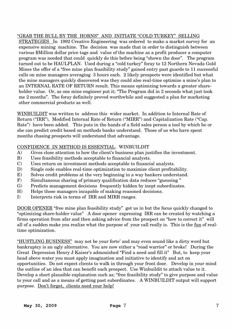
The purpose of WINBUILDIT “A” is to rapidly predict the INTERNAL RATE OF RETURN ofa proposed building in order to establish its investment and loan qualification.
WINBUILDIT takes advantage of the fact that the majority of buildings are a stack of box-likeshapes. Within the Program |Form6 - SHAPE |and | Form72 - SET BACKS | writes aparametric image of the proposed building .
| Form7 DETAILS | sets the range of structural steel shapes to be used.
The magnitude of lateral forces is determined from | Form65 – WIND | and | Form5 –SEISMIC |
Optional forms for | OPTIONAL SPACE PLANNING |, | OPTIONAL BEAM LOADS |, |ELEVATOR SHAFTS | and |FLOOR AND ROOF JOISTS | add diversity.
The forms above are saved within a single file at | Form21 – FILE HANDLING | by firstclicking onto | FILE BUILDING DESCRIPTION | at the menu bar.
Seven cost forms accept data from “RSMeanstm Square Foot Costs” while an eigth form coversthe client’s business plan. These forms are saved in a separate file system. The file systemused works as a relational data base. That is, any cost file will “stretch to fit any building size.
In that way at the click | COMPUTE | any | FILE BUILDING DESCRIPTION | will mergeto fit whatever | FILE COSTS | the user has selected. In this way several predictions can bemade to find the “sweet spot”, all in the time it takes for a coffee break.
A salient advantage is client participation.
May 30, 2009 Page 11 11
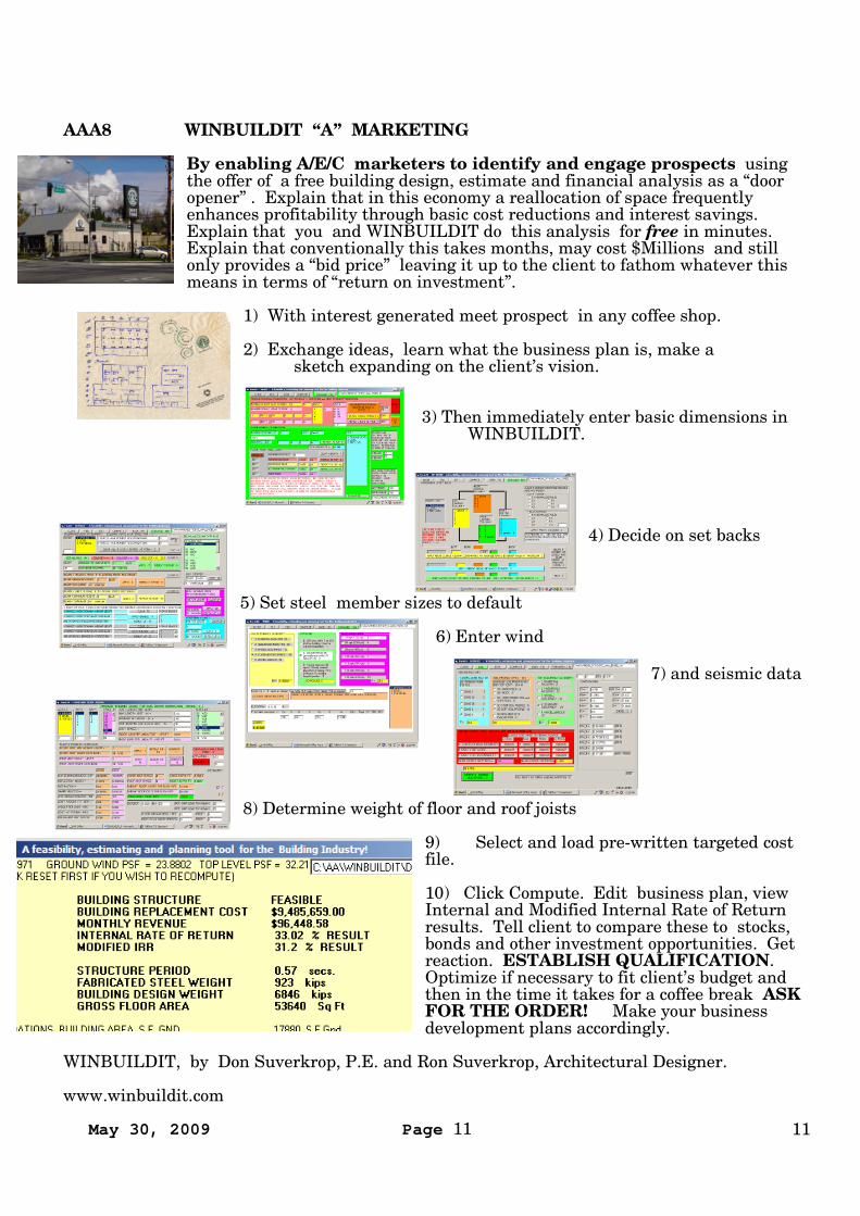
AAA8 WINBUILDIT “A” MARKETING
By enabling A/E/C marketers to identify and engage prospects usingthe offer of a free building design, estimate and financial analysis as a “dooropener” . Explain that in this economy a reallocation of space frequentlyenhances profitability through basic cost reductions and interest savings.Explain that you and WINBUILDIT do this analysis for free in minutes.Explain that conventionally this takes months, may cost $Millions and stillonly provides a “bid price” leaving it up to the client to fathom whatever thismeans in terms of “return on investment”.
1) With interest generated meet prospect in any coffee shop.
2) Exchange ideas, learn what the business plan is, make asketch expanding on the client’s vision.
3) Then immediately enter basic dimensions inWINBUILDIT.
4) Decide on set backs
5) Set steel member sizes to default
6) Enter wind
7) and seismic data
8) Determine weight of floor and roof joists
9) Select and load pre-written targeted costfile.
10) Click Compute. Edit business plan, viewInternal and Modified Internal Rate of Returnresults. Tell client to compare these to stocks,bonds and other investment opportunities. Getreaction. ESTABLISH QUALIFICATION.Optimize if necessary to fit client’s budget andthen in the time it takes for a coffee break ASKFOR THE ORDER! Make your businessdevelopment plans accordingly.
WINBUILDIT, by Don Suverkrop, P.E. and Ron Suverkrop, Architectural Designer.
www.winbuildit.com
May 30, 2009 Page 12 12
FFF06 SHAPE DATA ENTRY , Form6
WINBUILDIT “A” requires that the building shape be defined.
The Program user may wish to visualize how lateral forces are taken in both the X and Ydirections For the purposes of this Program it is logical to select an arrangement where thelines of lateral resisting columns are continuous from the window line of the top-most floordown to foundation. Most buildings fit the functionality of this arrangement.
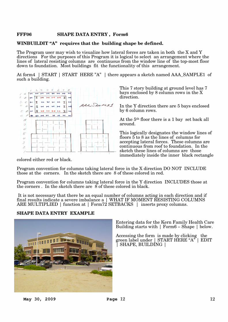
At form4 | START | START HERE ”A” | there appears a sketch named AAA_SAMPLE1 ofsuch a building.
This 7 story building at ground level has 7bays enclosed by 8 column rows in the Xdirection.
In the Y direction there are 5 bays enclosedby 6 column rows.
At the 5th floor there is a 1 bay set back allaround.
This logically designates the window lines offloors 5 to 8 as the lines of columns foraccepting lateral forces. These columns arecontinuous from roof to foundation. In thesketch these lines of columns are thoseimmediately inside the inner black rectangle
colored either red or black.
Program convention for columns taking lateral force in the X direction DO NOT INCLUDEthose at the corners. In the sketch there are 8 of these colored in red.
Program convention for columns taking lateral force in the Y direction INCLUDES those atthe corners . In the sketch there are 8 of these colored in black.
It is not necessary that there be an equal number of columns acting in each direction and iffinal results indicate a severe imbalance a | WHAT IF MOMENT RESISTING COLUMNSARE MULTIPLIED | function at | Form72 SETBACKS | inserts proxy columns.
SHAPE DATA ENTRY EXAMPLE
Entering data for the Kern Family Health CareBuilding starts with | Form6 – Shape | below.
Accessing the form is made by clicking thegreen label under | START HERE “A” | EDIT| SHAPE, BUILDING |
May 30, 2009 Page 13 13
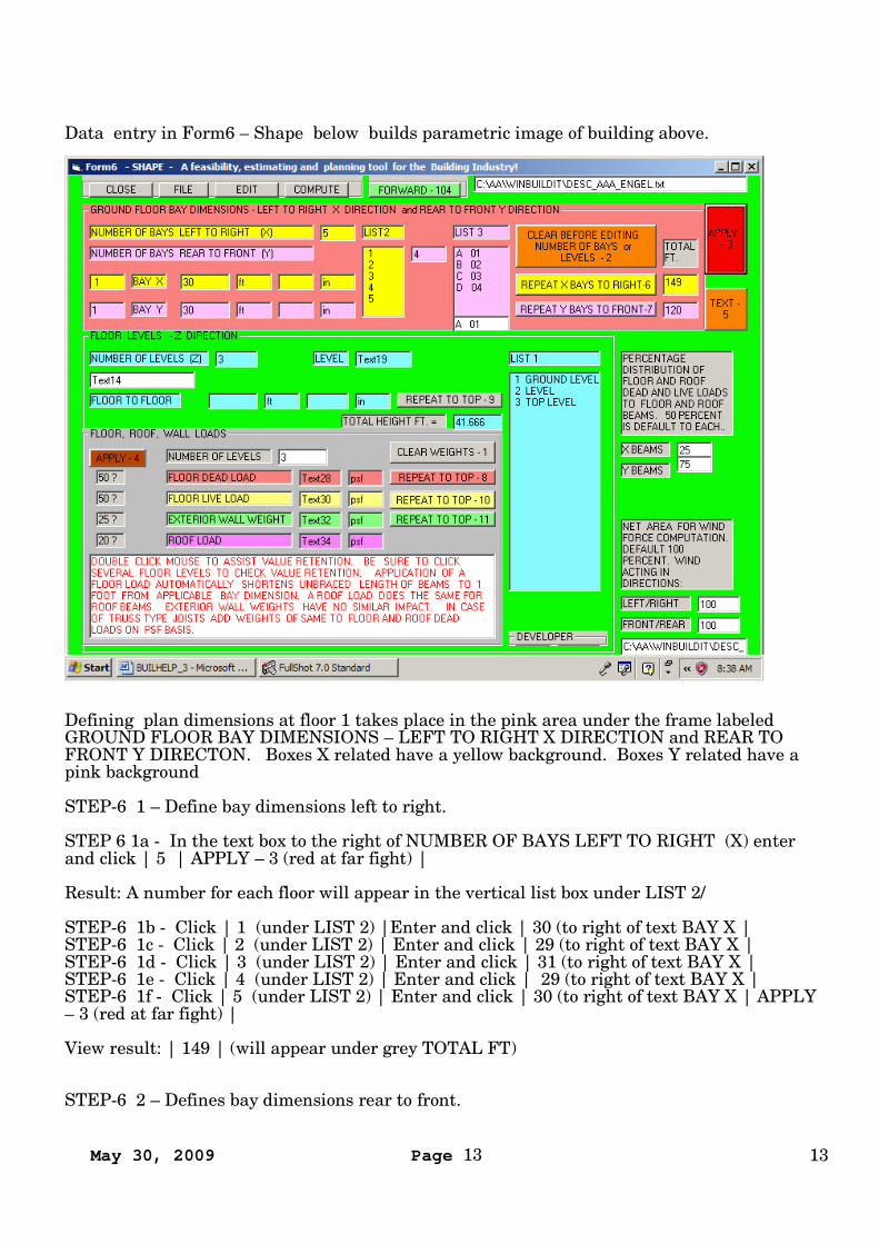
Data entry in Form6 – Shape below builds parametric image of building above.
Defining plan dimensions at floor 1 takes place in the pink area under the frame labeledGROUND FLOOR BAY DIMENSIONS – LEFT TO RIGHT X DIRECTION and REAR TOFRONT Y DIRECTON. Boxes X related have a yellow background. Boxes Y related have apink background
STEP-6 1 – Define bay dimensions left to right.
STEP 6 1a - In the text box to the right of NUMBER OF BAYS LEFT TO RIGHT (X) enterand click | 5 | APPLY – 3 (red at far fight) |
Result: A number for each floor will appear in the vertical list box under LIST 2/
STEP-6 1b - Click | 1 (under LIST 2) |Enter and click | 30 (to right of text BAY X |STEP-6 1c - Click | 2 (under LIST 2) | Enter and click | 29 (to right of text BAY X |STEP-6 1d - Click | 3 (under LIST 2) | Enter and click | 31 (to right of text BAY X |STEP-6 1e - Click | 4 (under LIST 2) | Enter and click | 29 (to right of text BAY X |STEP-6 1f - Click | 5 (under LIST 2) | Enter and click | 30 (to right of text BAY X | APPLY– 3 (red at far fight) |
View result: | 149 | (will appear under grey TOTAL FT)
STEP-6 2 – Defines bay dimensions rear to front.
May 30, 2009 Page 14 14
STEP-6 2a In the lavender text box to the right of | NUMBER OF BAYS REAR TO FRONT(Y) | enter and click | 4 |
In the adjoining lavender list box under label | LIST 3 | are listed alphabetic and numericalrepresentations for each bay in the rear to front direction.
STEP-6 2b - Click | A 01 (under LIST 3) |Enter and click | 30 (to right of text BAY Y) |STEP-6 2c - Click | REPEAT Y BAYS TO FRONT (lavender at right) |
View result: | 120 | (will appear under grey TOTAL FT) |
Note: This demonstrates an alternate method of entering bay dimension when they are all thesame.
STEP-6 3 - Now move attention to the green area below for vertical dimensions.
STEP-6 3a – Establish the number of floors. Enter and click | 3 | in the light blue text box tothe right of | NUMBER OF LEVELS (Z) |
A listing for each floor will appear in the vertical list box to the right labeled | LIST 1 |
STEP-6 3b - Set floor to floor dimension of level 1. Click | 1 GROUND LEVEL | in list boxat right. Enter and click | 13.166 in blue text box to right of | FLOOR TO FLOOR |
STEP-6 3c - Set floor to floor dimension of level 2. Click | 2 LEVEL | in list box at right.Enter and click | 15.5 in blue text box to right of | FLOOR TO FLOOR |
STEP-6 3d - Set floor to floor dimension of level 3. Click | 2 TOP LEVEL | in list box atright. Enter and click | 13 in blue text box to right of | FLOOR TO FLOOR | APPLY – 3 |
Total height | 41.666 | will appear in the text box to right of grey label | TOTAL HEIGHTFT. = |
STEP-6 4 - Now direct attention to the grey area below for loads and weights.
The loads entered in this category must include all loads and weights exclusive of thestructural steel frame and those covered by data entry in any NON-MANDATORY OPTION
May 30, 2009 Page 15 15
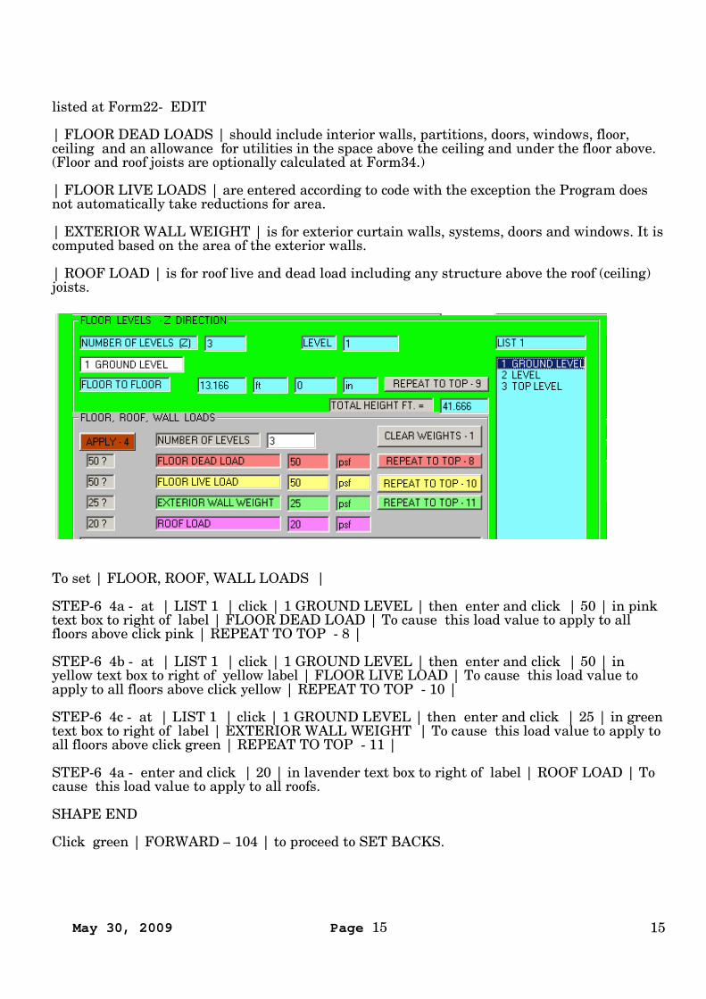
listed at Form22- EDIT
| FLOOR DEAD LOADS | should include interior walls, partitions, doors, windows, floor,ceiling and an allowance for utilities in the space above the ceiling and under the floor above.(Floor and roof joists are optionally calculated at Form34.)
| FLOOR LIVE LOADS | are entered according to code with the exception the Program doesnot automatically take reductions for area.
| EXTERIOR WALL WEIGHT | is for exterior curtain walls, systems, doors and windows. It iscomputed based on the area of the exterior walls.
| ROOF LOAD | is for roof live and dead load including any structure above the roof (ceiling)joists.
To set | FLOOR, ROOF, WALL LOADS |
STEP-6 4a - at | LIST 1 | click | 1 GROUND LEVEL | then enter and click | 50 | in pinktext box to right of label | FLOOR DEAD LOAD | To cause this load value to apply to allfloors above click pink | REPEAT TO TOP - 8 |
STEP-6 4b - at | LIST 1 | click | 1 GROUND LEVEL | then enter and click | 50 | inyellow text box to right of yellow label | FLOOR LIVE LOAD | To cause this load value toapply to all floors above click yellow | REPEAT TO TOP - 10 |
STEP-6 4c - at | LIST 1 | click | 1 GROUND LEVEL | then enter and click | 25 | in greentext box to right of label | EXTERIOR WALL WEIGHT | To cause this load value to apply toall floors above click green | REPEAT TO TOP - 11 |
STEP-6 4a - enter and click | 20 | in lavender text box to right of label | ROOF LOAD | Tocause this load value to apply to all roofs.
SHAPE END
Click green | FORWARD – 104 | to proceed to SET BACKS.
May 30, 2009 Page 16 16
FFF72 SETBACKS - Form72 DVD
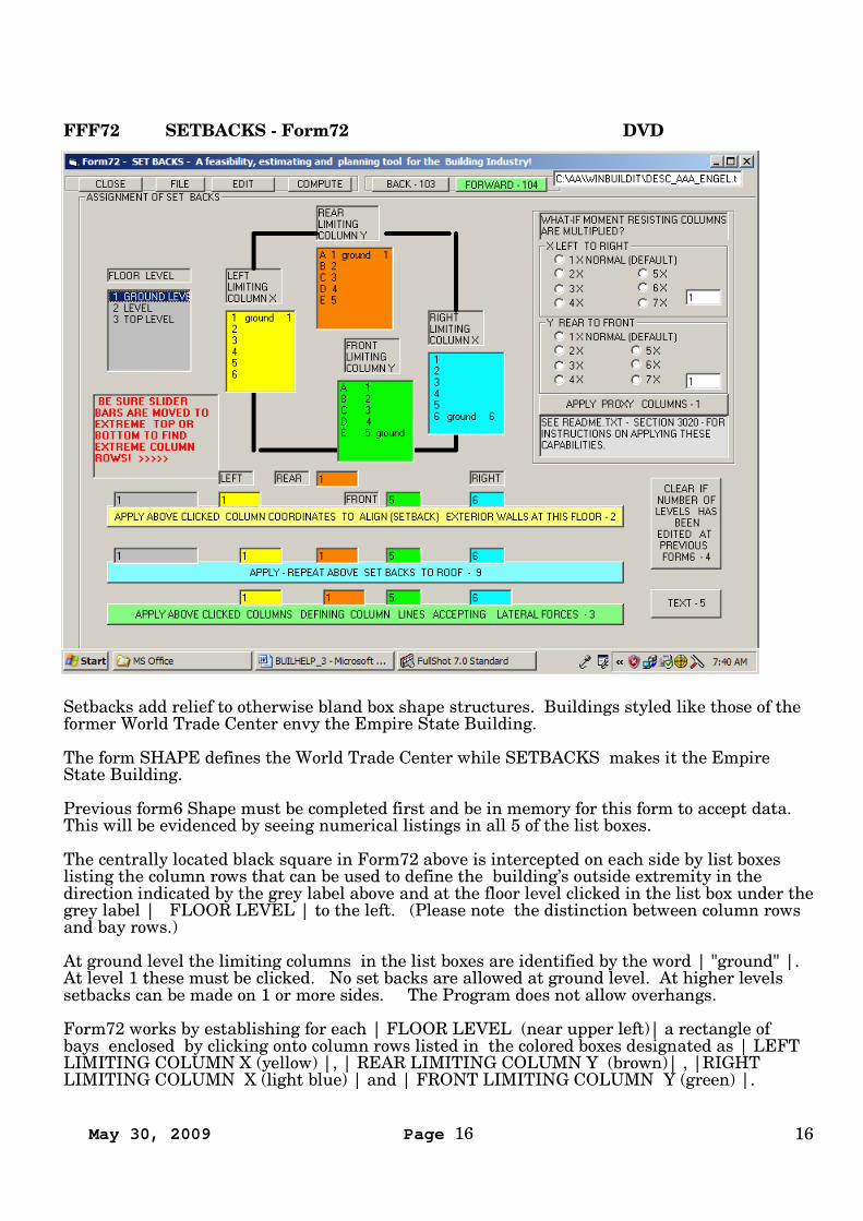
Setbacks add relief to otherwise bland box shape structures. Buildings styled like those of theformer World Trade Center envy the Empire State Building.
The form SHAPE defines the World Trade Center while SETBACKS makes it the EmpireState Building.
Previous form6 Shape must be completed first and be in memory for this form to accept data.This will be evidenced by seeing numerical listings in all 5 of the list boxes.
The centrally located black square in Form72 above is intercepted on each side by list boxeslisting the column rows that can be used to define the building’s outside extremity in thedirection indicated by the grey label above and at the floor level clicked in the list box under thegrey label | FLOOR LEVEL | to the left. (Please note the distinction between column rowsand bay rows.)
At ground level the limiting columns in the list boxes are identified by the word | "ground" |.At level 1 these must be clicked. No set backs are allowed at ground level. At higher levelssetbacks can be made on 1 or more sides. The Program does not allow overhangs.
Form72 works by establishing for each | FLOOR LEVEL (near upper left)| a rectangle ofbays enclosed by clicking onto column rows listed in the colored boxes designated as | LEFTLIMITING COLUMN X (yellow) |, | REAR LIMITING COLUMN Y (brown)| , |RIGHTLIMITING COLUMN X (light blue) | and | FRONT LIMITING COLUMN Y (green) |.
May 30, 2009 Page 17 17
STEP-72 1
Under | FLOOR LEVEL | click | 1 GROUND LEVEL | to initiate enclosing bays surroundedby a rectangle of column rows in colored boxes designatedunder | LEFT LIMITING COLUMN X (yellow) | by clicking | 1 ground 1|,under |REAR LIMITING COLUMN Y (brown) | by clicking | A 1 ground |,under |RIGHT LIMITING COLUMN (light blue) | by clicking | * ground |,under | FRONT LIMITING COLUMN (green) |by clicking | * ground |
* = max number of bays in designated direction.
STEP-72 2 ALWAYS accept these designations, for | 1 GROUND LEVEL | by clicking theyellow command bar below entitled | APPLY ABOVE CLICKED COLUMN COORDINATES…………………. – 2 |
STEP-72 3 ALWAYS extend these designations to the roof by clicking light blue commandbar entitled | APPLY – REPEAT ABOVE SET BACKS TO ROOF – 9 |
STEP-72 4 IF THERE ARE NO SETBACKS IT IS RECOMMENDED that you click the lightgreen command bar entitled | APPLY ABOVE CLICKED COLUMNS DEFINING COLUMNSACCEPTING LATERAL FORCES – 3 |
STEP-72 5 IF THERE ARE SETBACKS repeat STEP-72 1 followed by STEP-72 3 , startingat the lowest floor, for each floor at which a SETBACK occurs clicking the desired | FLOORLEVEL | and defining | LIMITING COLUMN |. At the conclusion of entering data for thehighest setback click | APPLY ABOVE CLICKED COLUMNS DEFINING COLUMNSACCEPTING LATERAL FORCES – 3 |
In the upper right portion of the monitor is an area labeled "WHAT IF MOMENT RESISTINGCOLUMNS ARE MULTIPLIED"
If after computation it is found that one or more moment resisting column(s), acting in eitherthe X or Y direction, are found to be over-stressed then the number of columns acting in thatdirection can be multiplied by the factors indicated by clicking onto the appropriate optionbutton. The default is 1 in both directions. This becomes an option when either a W36 orW&M Default shape data base has been selected for columns at Form7 and a W36X798 sizecomputed. Over-stress is indicated when the output appears in red. This is triggered by aCombined Stress Result (Interaction) equal or greater than 1. For the curious the backgroundcalculations of any member may be accessed by clicking onto | DETAIL – 13 | aftercomputation at | Form9 – COMPUTE |
Click FILE at tool bar to save your work or;
Click FORWARD - 104 at top. (green)
Form7 - DETAILS will appear.
END OF Form72 - SETBACKS
May 30, 2009 Page 18 18
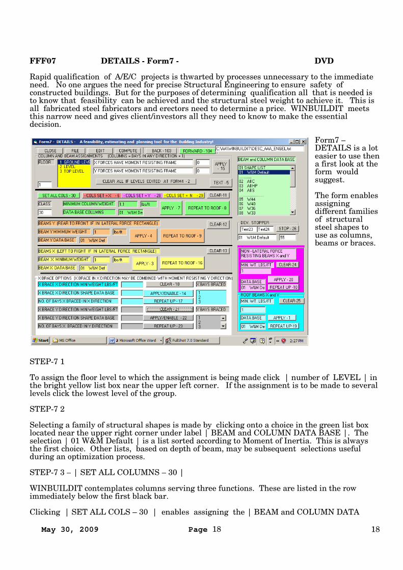
FFF07 DETAILS - Form7 - DVD
Rapid qualification of A/E/C projects is thwarted by processes unnecessary to the immediateneed. No one argues the need for precise Structural Engineering to ensure safety ofconstructed buildings. But for the purposes of determining qualification all that is needed isto know that feasibility can be achieved and the structural steel weight to achieve it. This isall fabricated steel fabricators and erectors need to determine a price. WINBUILDIT meetsthis narrow need and gives client/investors all they need to know to make the essentialdecision.
Form7 –DETAILS is a loteasier to use thena first look at theform wouldsuggest.
The form enablesassigningdifferent familiesof structuralsteel shapes touse as columns,beams or braces.
STEP-7 1
To assign the floor level to which the assignment is being made click | number of LEVEL | inthe bright yellow list box near the upper left corner. If the assignment is to be made to severallevels click the lowest level of the group.
STEP-7 2
Selecting a family of structural shapes is made by clicking onto a choice in the green list boxlocated near the upper right corner under label | BEAM and COLUMN DATA BASE |. Theselection | 01 W&M Default | is a list sorted according to Moment of Inertia. This is alwaysthe first choice. Other lists, based on depth of beam, may be subsequent selections usefulduring an optimization process.
STEP-7 3 – | SET ALL COLUMNS – 30 |
WINBUILDIT contemplates columns serving three functions. These are listed in the rowimmediately below the first black bar.
Clicking | SET ALL COLS – 30 | enables assigning the | BEAM and COLUMN DATA
May 30, 2009 Page 19 19
BASE | selected, such as | 01 W&M Default | to all columns.
Clicking the green | APPLY – 7 | enters the data.
Clicking the green | REPEAT TO ROOF | extends the same choice to the upper levels.
STEP-7 4 – | BEAMS Y (REAR TO FRONT IF IN LATERAL FORCE RECTANGLE ) |
Clicking the light brown? | APPLY – 4 | selects | 01 W&M Default | shape for thisapplication.
Clicking the light brown? | REPEAT TO ROOF – 9 | repeats this assignment to the roof.
STEP-7 5 - | BEAMS X (LEFT TO RIGHT IF IN LATERAL FORCE RECTANGLE} |
Clicking the yellow | APPLY – 3 | selects | 01 W&M Default | shape for this application.
Clicking the yellow? | REPEAT TO ROOF – 16 | repeats this assignment to the roof.
STEP-7 6 - | NON-LATERAL FORCE RESISTING BEAMS X and Y | located near lowerright.
Click pink | APPLY – 20 | selects | 01 W&M Default | shape for this application.
Click pink | REPEAT UP – 10 | repeats this assignment to the roof.
STEP-7 7 - | ROOF BEAMS X and Y | lower right corner
Click | APPLY – 1 | selects | 01 W&M Default | shape for this application.
Click | REPEAT UP – 19 | repeats this assignment to the roof.
NOTE: Foregoing STEPS 1 to 7 obtain data for the qualification purpose
May 30, 2009 Page 20 20
FFF65 WIND - Form65 - DVD
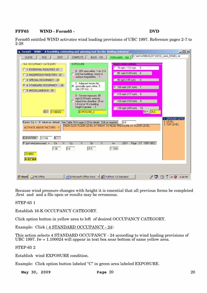
Form65 entitled WIND activates wind loading provisions of UBC 1997. Reference pages 2-7 to2-28
Because wind pressure changes with height it is essential that all previous forms be completed.first and and a file open or results may be erroneous.
STEP-65 1
Establish 16-K OCCUPANCY CATEGORY.
Click option button in yellow area to left of desired OCCUPANCY CATEGORY.
Example: Click ( 4 STANDARD OCCUPANCY - 24)
This action selects 4 STANDARD OCCUPANCY - 24 according to wind loading provisions ofUBC 1997. Iw = 1.100024 will appear in text box near bottom of same yellow area.
STEP-65 2
Establish wind EXPOSURE condition.
Example: Click option button labeled "C" in green area labeled EXPOSURE.
May 30, 2009 Page 21 21
This action selects EXPOSURE_C according to wind loading provisions of UBC 1997 andcauses "EXPOSURE_C" to appear in text box near bottom of same green area.
STEP-65 3
Establishes BASIC WIND SPEED.
Example: Click within magenta colored area labeled BASIC WIND SPEED the option buttonlabeled ( 100 mph(161 kph 7 )
This action selects 100 mph(161 kph 7 for basic wind speed according to provisions of UBC1997. Qs = 25.6 will appear in text box near bottom of purple area.
STEP-65 4
Action computes the factors selected in the above yellow, green and magenta colored areas .
Click brown | ACTIVATE ABOVE FACTORS - 1 command button | located mid-height belowthe yellow area.
This action enables reading wind pressures displayed in yellow text boxes at lower left. Clickother levels and wind pressure will change accordingly. Selection for each level is automaticwithin computation.
STEP-65 5
Goto Seismic form.
Click green ( FORWARD - 104 ) command button in tool bar at top of monitor.
May 30, 2009 Page 22 22
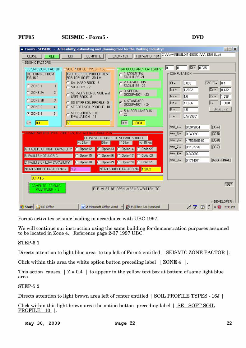
FFF05 SEISMIC - Form5 - DVD
Form5 activates seismic loading in accordance with UBC 1997.
We will continue our instruction using the same building for demonstration purposes assumedto be located in Zone 4. Reference page 2-37 1997 UBC.
STEP-5 1
Directs attention to light blue area to top left of Form5 entitled | SEISMIC ZONE FACTOR |.
Click within this area the white option button preceding label | ZONE 4 |.
This action causes | Z = 0.4 | to appear in the yellow text box at bottom of same light bluearea.
STEP-5 2
Directs attention to light brown area left of center entitled | SOIL PROFILE TYPES - 16J |
Click within this light brown area the option button preceding label | SE - SOFT SOILPROFILE - 10 |.
May 30, 2009 Page 23 23
This action causes | SE | to appear in yellow text box at bottom of same light brown area.
STEP-5 3
Directs attention to the green area right of center labeled | 16-K OCCUPANCY CATEGORY |.
Click within the green area the white option button preceding label | 4 STANDARDOCCUPANCY - 24 |.
This action causes | Ip = 1.0004 | to appear in yellow text box at bottom of same green area.
STEP-5 4
Directs attention to red area near bottom left labeled | SEISMIC SOURCE TYPE | - For moreon this SEE 16-S, 16-T and 16-U - PAGE 2-35.
Click within red area labeled | SEISMIC SOURCE TYPE etc. | the white option buttonlabeled | Option 13 |.
This action sets the fault classification as | A - FAULTS OF HIGH CAPABILITY | with a |CLOSEST DISTANCE TO SEISMIC SOURCE | as |5 km | and enables reading | NEARSOURCE FACTOR Na | = |1.2002 | in the yellow text box at bottom right of same red areaand | NEAR SOURCE FACTOR Nv | = | 1.6 | in adjoining pink text box at lower left insame red area.
STEP-5 5
Click green command button located at lower left of Form5 entitled | COMPUTE SEISMICMULTIPLIER - 3 |.
Read seismic multiplier | .1715 | in yellow text box near lower left.
NOTE: Because building height enters into computation of seismic factor a file must be open orbeing written to during computation of seismic factor.
Direct your attention to top to tool bar of Form5.
Click "FILE" command button at top/left of monitor, (green)
May 30, 2009 Page 24 24
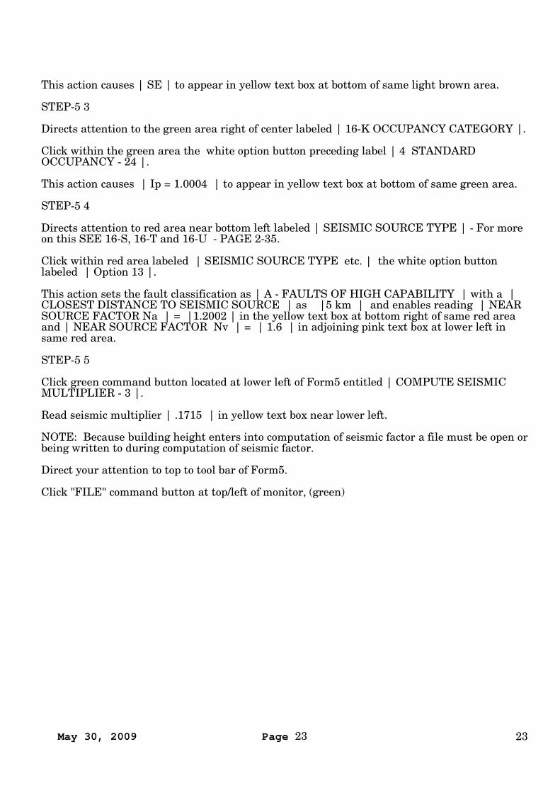
FFF34 FLOOR AND ROOF JOISTS - Form34 – DVD
Form34 - FLOOR AND ROOF JOISTS is used when conventional AISC beams are preferredrather than "Steel Joists" of the truss type such as those illustrated in section "B10Superstructure" of "RSMeans Square Foot Costs"
Form34 determines a TOTAL WEIGHT by adding the weight of floor and roof joists for rangesof floor levels of a building and then adds that sub total to the fabricated steel weight of thebuilding and computing cost on the same basis as fabricated steel.
Form34 works to standardize on one size shape for ranges of levels while meeting the designrequirements of the worse case. It provides joists for every bay with no deductions for atriums,elevator shafts, stair wells etc.
Form34 can only function from a computed file. Do that by loading your current file andcomputing.
Access FLOOR AND ROOF JOISTS - Form34 by clicking its command button located underNON-MANDATORY OPTIONS at Form22 - EDIT.
The weight of joists is applied selectively based on requirements. If any mandatory form hasbeen edited then this form must be edited. WINBUILDIT assumes that joists are aligned in
May 30, 2009 Page 25 25
the X direction.
We will continue to use the KERN FAMILY HEALTH CARE case study to demonstrate.
STEP-34 1
The first step is for the user to select the most structurally demanding bay from a floor joiststrength standpoint for the range of levels being computed . This may stand out as the baywith the largest horizontal directions and floor load.
Otherwise select any loaded bay. For our example we will select the Northeast corner bay onthe ground floor.
STEP-34 2 Click |1 GROUND | in yellow list box in upper left under label | Level Z
STEP-34 3 Click | 1 | in adjoining blue list box labeled | BAY X |.
STEP-34 4 Click | 1 | in adjoining blue list box labeled | BAY Y |.
These steps have located the bay that will be used as a model for the rest of the buildingregardless of the size of the other bays.
The next action establishes the contributing area or width between joists. A greater widthcontributes a greater load to the joists and tends to increase the size or depth of joists. A lesserwidth does the opposite. We have observed that 90 inches is common. One consideration isthat floor joists tend to detract from useable space under for HVAC ducts. Within buildingheight restrictions in some cities shallower floor joists might add another revenue producingfloor and thus change the overall economics. Should this be the case heavy shallow floor joistscould be real cheap.
STEP-34 5 Click | 84 | in adjoining pink list box under the label | SPACE IN |.
This action computes that the nearest joist spacing to 84 inches that will evenly divide the baywidth is 90 inches.
Accordingly the following results are displayed under | JOIST LENGTH AND LOADS |
| MAX LENGTH JOIST – IN = | = 372| AVERAGE BAY WDITH - IN | = 360| CONTRIBUTING WIDTH EACH JOIST – IN | = 90| JOIST SPACES = | = 4| FLOOR LOAD PER LINEAL FOOT – KIPS/FT | = 0.75| ROOF LOAD PER LINEAL FT – KIPS/FT | = .15
The next action is to select a shape data base. For our case study we select W16 for both floorand roof joists.
STEP-34 6
Click W16 in the green list box under the label SHAPE LIST in the upper right corner.
STEP-34 7
Applies these parameters to Floor joists by:
Clicking the light brown | APPLY – 7 | REPEAT UP – 14 | COMPUTE – 1 |
May 30, 2009 Page 26 26
The results will be seen in the column under the light brown | FLOOR | near the lower rightcorner of the monitor.
STEP-34 8
Applies these parameters to Roof joists by:
Clicking the pink | APPLY – 15 | REPEAT UP – 3 | COMPUTE – 16 |
The results will be seen in the column under the pink | ROOF | also near the lower rightcorner of the monitor.
STEP-34 9
Is to totalize this data and place it in memory.
Click | READ FILE – 4 | command button near mid height of monitor at far right.
STEP-34 – 10
Is to click the green command bar in the tool bar space entitled | PROGRAM REQUIRESSAVING THIS DATA BEFORE COMPUTATION – RETURN – 6 |
You will note that after clicking STEP-34 – 9 that some of the information disappears. This isnot saved data.
End of Form34
May 30, 2009 Page 27 27
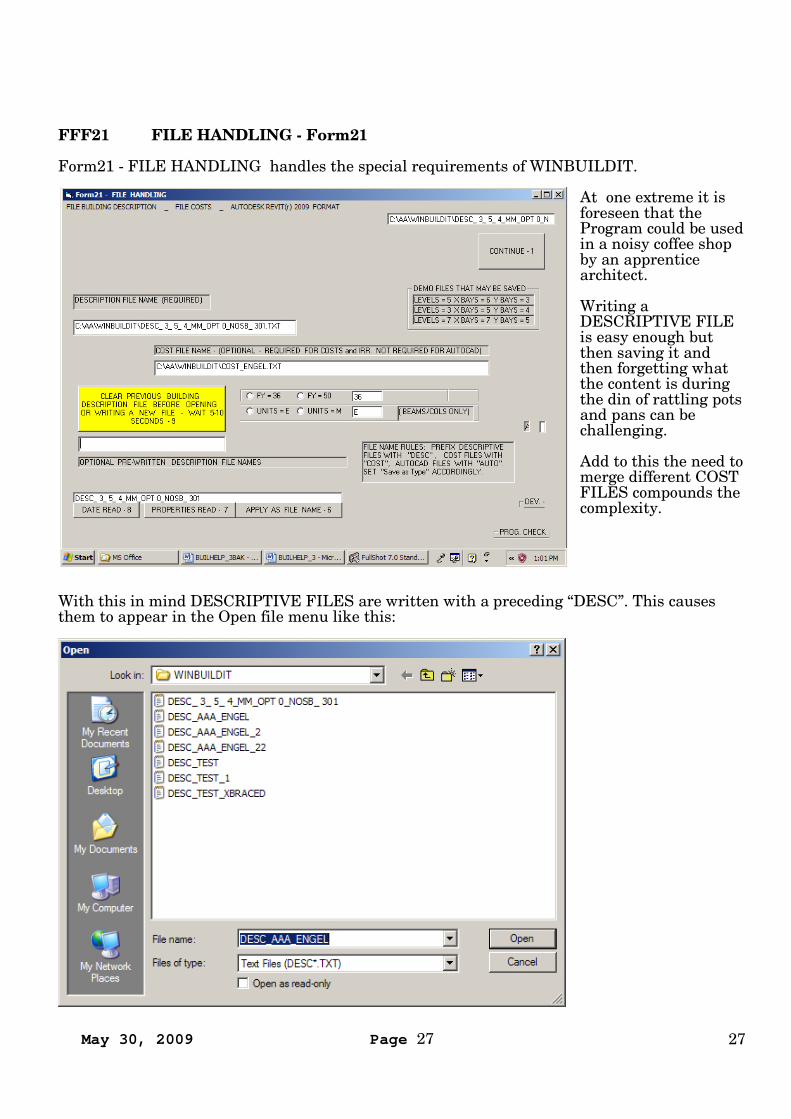
FFF21 FILE HANDLING - Form21
Form21 - FILE HANDLING handles the special requirements of WINBUILDIT.
At one extreme it isforeseen that theProgram could be usedin a noisy coffee shopby an apprenticearchitect.
Writing aDESCRIPTIVE FILEis easy enough butthen saving it andthen forgetting whatthe content is duringthe din of rattling potsand pans can bechallenging.
Add to this the need tomerge different COSTFILES compounds thecomplexity.
With this in mind DESCRIPTIVE FILES are written with a preceding “DESC”. This causesthem to appear in the Open file menu like this:
May 30, 2009 Page 28 28
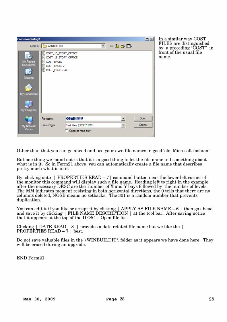
In a similar way COSTFILES are distinguishedby a preceding “COST” infront of the usual filename.
Other than that you can go ahead and use your own file names in good ‘ole Microsoft fashion!
But one thing we found out is that it is a good thing to let the file name tell something aboutwhat is in it. So in Form21 above you can automatically create a file name that describespretty much what is in it.
By clicking onto | PROPERTIES READ – 7| command button near the lower left corner ofthe monitor this command will display such a file name. Reading left to right in the exampleafter the necessary DESC are the number of X and Y bays followed by the number of levels,The MM indicates moment resisting in both horizontal directions, the 0 tells that there are nocolumns deleted, NOSB means no setbacks, The 301 is a random number that preventsduplication.
You can edit it if you like or accept it by clicking | APPLY AS FILE NAME – 6 | then go aheadand save it by clicking | FILE NAME DESCRIPTION | at the tool bar. After saving noticethat it appears at the top of the DESC - Open file list.
Clicking | DATE READ – 8 | provides a date related file name but we like the |PROPERTIES READ – 7 | best.
Do not save valuable files in the \WINBUILDIT\ folder as it appears we have done here. Theywill be erased during an upgrade.
END Form21
May 30, 2009 Page 29 29
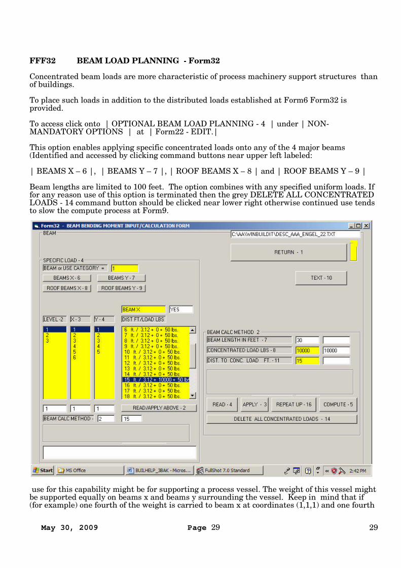
FFF32 BEAM LOAD PLANNING - Form32
Concentrated beam loads are more characteristic of process machinery support structures thanof buildings.
To place such loads in addition to the distributed loads established at Form6 Form32 isprovided.
To access click onto | OPTIONAL BEAM LOAD PLANNING - 4 | under | NON-MANDATORY OPTIONS | at | Form22 - EDIT.|
This option enables applying specific concentrated loads onto any of the 4 major beams(Identified and accessed by clicking command buttons near upper left labeled:
| BEAMS X – 6 |, | BEAMS Y – 7 |, | ROOF BEAMS X – 8 | and | ROOF BEAMS Y – 9 |
Beam lengths are limited to 100 feet. The option combines with any specified uniform loads. Iffor any reason use of this option is terminated then the grey DELETE ALL CONCENTRATEDLOADS - 14 command button should be clicked near lower right otherwise continued use tendsto slow the compute process at Form9.
use for this capability might be for supporting a process vessel. The weight of this vessel mightbe supported equally on beams x and beams y surrounding the vessel. Keep in mind that if(for example) one fourth of the weight is carried to beam x at coordinates (1,1,1) and one fourth

May 30, 2009 Page 30 30
to beam y at the same coordinates (1,1,1) then one fourth of the weight needs to be supported atan opposing beam x at coordinates (1,1,2) and one fourth of the weight needs to be supported atan opposing beam y at coordinates (1,2,1). For each the position from the column end of beamsmust be specified. Additional concentrated loads at each increment of beam length in feet maybe specified.
To apply select the applicable beam by clicking onto the appropriate grey labeled commandbuttons above the yellow list boxes entitled | BEAMS X - 6, BEAMS Y - 7, ROOF BEAMS - Xor ROOF BEAMS Y - 9. Then click onto the LEVEL - 2, X-3 and Y-4 coordinates to which theselected beam is associated.
Remember, the Z,X,Y coordinates of beams carry the same coordinate identification as thecolumns to which they are connected. In the case of beams x at their left/west end and beams yat their rear/north end.
Clicking onto READ/APPLY ABOVE - 2 activates display of the identified beam member in thelarge square list box. Clicking onto the specific distance from the column center displaysDIST. TO CONC. LOAD FT.- 11 in the yellow text boxes at the right. Entry can then be madeof the CONCENTRATED LOAD LBS - 8 in the text box immediately above. Clicking APPLY -3, REPEAT UP - 16 if appropriate and COMPUTE - 5 and then READ/APPLY ABOVE - 2again will cause entry of the force in right hand largest yellow list box.
After making entries be sure to save the file.
May 30, 2009 Page 31 31
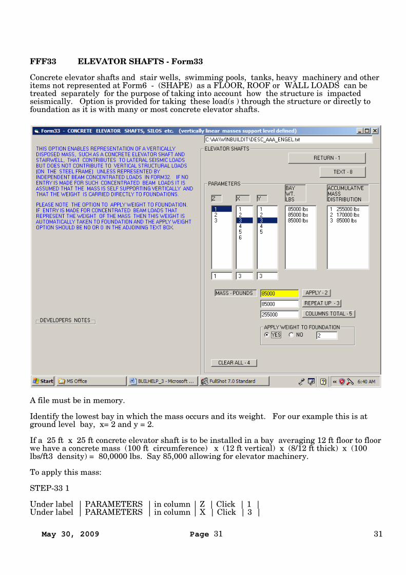
FFF33 ELEVATOR SHAFTS - Form33
Concrete elevator shafts and stair wells, swimming pools, tanks, heavy machinery and otheritems not represented at Form6 - (SHAPE) as a FLOOR, ROOF or WALL LOADS can betreated separately for the purpose of taking into account how the structure is impactedseismically. Option is provided for taking these load(s ) through the structure or directly tofoundation as it is with many or most concrete elevator shafts.
A file must be in memory.
Identify the lowest bay in which the mass occurs and its weight. For our example this is atground level bay, x= 2 and y = 2.
If a 25 ft x 25 ft concrete elevator shaft is to be installed in a bay averaging 12 ft floor to floorwe have a concrete mass (100 ft circumference) x (12 ft vertical) x (8/12 ft thick) x (100lbs/ft3 density) = 80,0000 lbs. Say 85,000 allowing for elevator machinery.
To apply this mass:
STEP-33 1
Under label | PARAMETERS | in column | Z | Click | 1 |Under label | PARAMETERS | in column | X | Click | 3 |
May 30, 2009 Page 32 32
Under label | PARAMETERS | in column | Y | Click | 3 |
STEP-33 2
In the lower right quarter of the monitor to the right of | MASS – POUNDS | clear the yellowtext box entitled | delete/edit this | and then type and click | 85000 | in the same yellow textbox.
STEP-33 3
Click | APPLY- 2 |
STEP-33 4
Click | REPEAT UP - 3 | if applicable.
STEP-33 5
Click | COLUMNS TOTAL – 5 |
Numbers in column under | ACCUMULATIVE MASS DISTRIBUTION | will then appear.
Numbers in column under | BAY WT. LBS | requires clicking another Z,X or Y value and thenre-clicking the proper value.
STEP-33 6
In box labeled | APPLY WEIGHT TO FOUNDATION | click | YES | if applicable.
STEP-33 7
Save the file.
Note: The Z,X,Y location we have chosen to place this elevator shaft is, in plan view, nearlycentral to the building and therefore an eccentric condition need not be treated. The Programdoes not treat eccentric conditions.
May 30, 2009 Page 33 33
FFF09 COMPUTE and ANALYZE - Form9
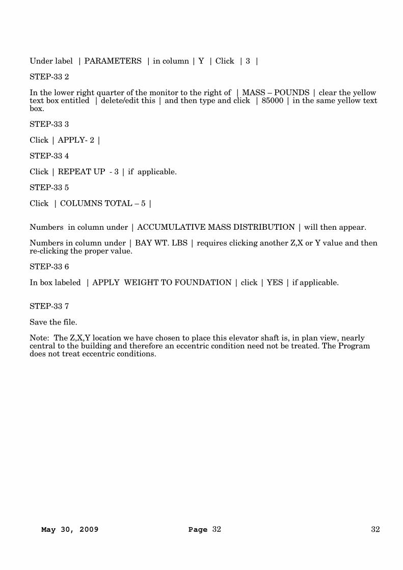
Form9 Computes Results.
STEP-9 1 Click green COMPUTE - 2. command button in right lower quadrant.Computation requires 1 to 200 seconds depending on building size and computer processorspeed.
If the type face of any of the output data is red this means that structural feasibility has notbeen attained or Structure Period exceeds that allowed by UBC 1997, 1630.2.2, 1 Method A,Steel Moment resisting frames. Page 2-14. These conditions must be corrected in order for anyother data to be truly useful. (In B&W hardcopy red appears as light grey in figures below.)
If the Structure period (short form) is unacceptable this is called out. To correct this the adviceof a Structural Engineer should be sought
May 30, 2009 Page 34 34
If the Structure period is acceptable and the type face of the output data is red and the | 01W&M Default | data base has been used for all members this means that basic geometricchanges must be made. This could mean a change in number or column space of the “red”members, substitute X bracing or a reduce building height .
To locate a specific overstressed member:
STEP-9 2 Click pink | REFRESH LIST BELOW | in lower right quadrant,STEP-9 3 Click | 50 SHAPE SUMMARY | in yellow list box lower right.STEP-9 4 Click | DISPLAY BELOW – 15 | light blue lower right.STEP-9 5 Click | CONTINUE | to review shape selection. Note those in red.
Action must be taken to remove the over stress and red condition. Actions that may be takeninclude reducing building height, select another shape data base, increase column density,reduce loads. To change shapes sizes click | DETAILS, FLOOR Form7 - 22 | from the |EDIT | menu Form22.
If the type face is black then voila! Eureka! The program displays a useful COST.
The REVENUE, INTERNAL RATE OF RETURN and MODIFIED INTERNAL RATE OFRETURN are initially based on data that currently resides in COST FILE 6. While this can befairly accurate it should be reviewed with the client to make sure it’s the clients “businessplan”. This is done by going to the next step.
STEP-9 6
Click blue | FINANCIAL RESULTS – 62 | command button located bottom near right.
STRUCTURAL OPTIMIZATION
Applying the | 01 W&M Default | data base for any member finds structural feasibilitywithout a guarantee of functionality. To ascertain this condition at | Form9 COMPUTE |click the pink | REFRESH LIST BELOW | in lower right quarter then click | 50 SHAPESUMMARY | then click light blue | DISPLAY BELOW – 15 | also in lower right quarter.
Within this display, for each floor level and member designation, establish an alternative database (other than the default) and minimum member weight per foot that will create a practicalstandardization.
Note column labeled "SET". Rows of Beams and columns labeled "X" are involved in lateralbracing in the X direction. Those labeled "Y" are involved in lateral bracing in the Y direction.Those labeled "N" are not involved in lateral bracing in either direction.
However, at the same time, it has been observed that frequently the total fabricated steelweight computed, between using the Default or carefully selected data bases, is notsignificantly different or even consequential in how it impacts Internal Rate of Return.
If |01 W&M Default | has been taken for all members and if over-stress warning appears thisis most likely due to a column spacing being too great. Try X bracing if permitted by local code.At | Form72 - SETBACKS |is a menu (upper right) that expedites analysis of this condition.(Entitled |WHAT IF MOMENT RESISTING COLUMNS ARE MULTIPLIED? |)
If closer column space obstructs interior space delete non-lateral force resisting columns via |OPTIONAL SPACE PLANNING - Form29 | or trigger X bracing at | Form7 – DETAILS | (ifpermitted)
May 30, 2009 Page 35 35
FFF17 BUSINESS PLAN OPTIMIZATION
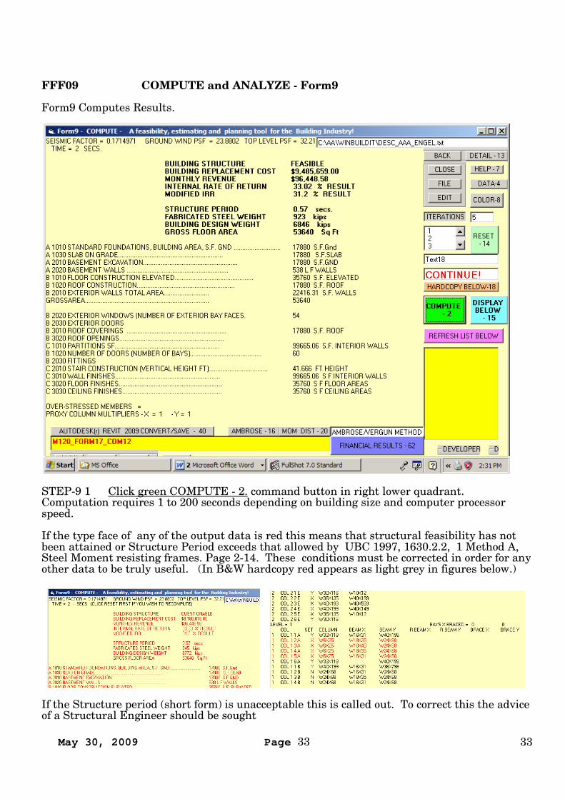
| Form17 | Resolves the naked truth about the value of a proposed building investment whilemaking a best-effort towards qualification
The INTERNAL RATE OF RETURN displayed in the green text box in the lower right quarterof the monitor is the metric of greatest interest to the client and user alike. At the same riskit must exceed the returns of competing investments to be attractive.
RISK can be quantified by inputing the extremes of a range of income possibilities perceived bythe client.
WINBUILDIT arrives at this result through a computation and merging of previously writtenand saved |DESCRIPTION | and | COST FILES
| COST | file are pre-prepared because of the time it takes to enter data from “RSMeanstm
Square Foot Costs”. The Program user may have several of these saved on his or hercomputer in order to address different customer needs. But as a consequence of this approachthe first | COST | file merged can only provide a “guess” as to what the INTERNAL RATEOF RETURN IS.
| Form17 - COSTS 6 | lists data in text boxes with white, yellow and green backgrounds.Data in white text boxes can be presumed to be “non-negotiable” Data in text boxes with ayellow background can be presumed to be subject to a degree of “negotiation”. The desiredresult, INTERNAL RATE OF RETURN, is in the text box with the green background.

May 30, 2009 Page 36 36
Click | MULTI USAGE ALTERNATIVE | upper right quarter if applicable.
| Form17 – COSTS 6 | must now be adjusted to reflect the client’s business plan by editingand clicking the following lines:
| 101 – YEARS ( INCLUDES CONST TIME) || 102 – PERCENT OF GROSS AREA (11) LEASED || 104 - RENT PER S.F./MONTH $ || 104.5 INFLATION PERCENT/YR APPLIED TO RENT || 104.6 INFLATION PERCENT APPLIED TO SALVAGE || 104.7 MONTHLY COSTS $ |
Click | APPLY THIS SECONDLY IF ………. | in lower left quarter.
Click | APPLY FIRST - 12 | in lower right quarter.
A new INTERNAL RATE OF RETURN will be displayed.
Out of this the client with the assistance of his banker should be able to provide clues as to thequalification.
If qualification is negative or borderline another | COST FILE | should be considered orediting by contractor and Architect of:
| 22 - MISCELLANEOUS ADDITION || 26 – ARCHITECTS FEES % OF 25 || 28 – LOCATION MODIFIER |
Form17 does is bring order to this madness. Each party at the table can see how theircontribution contributes to the end result while softening demands when the end result ismarginal.
May 30, 2009 Page 37 37
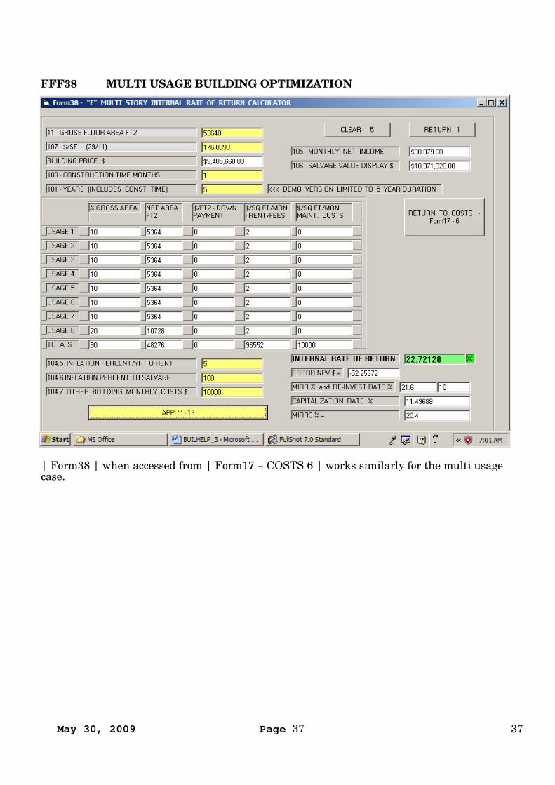
FFF38 MULTI USAGE BUILDING OPTIMIZATION
| Form38 | when accessed from | Form17 – COSTS 6 | works similarly for the multi usagecase.

May 30, 2009 Page 38 38
FFF23 COSTS_1, SUBSTRUCTURE, SHELLFFF14 COSTS_2, EXTERIOR, DOORS, ROOFFFF13 COSTS_3, PARTITIONS, DOORSFFF15 COSTS-4, ELEVATORS, PLUMBINGFFF18 COSTS-4.5, PLUMBINGFFF19 COSTS_4.8, HEAT, COOLING, PIPINGFFF16, COSTS 5, MISCFFF17 COSTS 6, SUMMARY, ANALYSIS
CONTENTS - FORMS SAVED AS COST FILES
(Form23 - COSTS_1 - SUBSTRUCTURE, SHELL , EXTERIOR ENCLOSURE)(Form14 - COSTS_2 - EXTERIOR, CURTAIN WALLS, DOORS, ROOF)(Form13 - COSTS_3 - PARTITIONS, DOORS, STAIRS, FLOOR AND CEILING)(Form15 - COSTS_4 - ELEVATORS, ESCALATORS PLUS PLUMBING SYSTEMS)(Form18 - COSTS_4.5 - MORE PLUMBING SYSTEMS)(Form19 _ COST 4.8 - DRAIN, PIPING, COOLING AND HEATING SYSTEMS)(Form16 - COSTS 5 - MISCELLANEOUS)(Form17 - COSTS 6 - COST SUMMARY AND INVESTMENT ANALYSIS)
For help on COSTS see "RSMeansr Square Foot Costs" (tel 714 422 5101)

May 30, 2009 Page 39 39
FFF03 FINANCIAL ANALYSIS
WINBUILDIT'S IRR / MIRR CALCULATORS take the mystery out of business investment.
IRR assumes that positive cash flows are re-invested (such as in the business) and continue toreturn the same interest rate as the IRR rate.
MIRR assumes that positive cash flows are paid out (such as to stockholders) and earn(usually) a lower interest rate. For Program purposes this lower rate is taken as the COST OFCAPITAL which for some CALCULATORS can be edited or for default purposes this rate istaken as 10% While conceivable the program does not permit an MIRR rate to exceed the IRRrate.
Taking advantage of internal code for computing IRR and MIRR WINBUILDIT provides easy-to-use calculators for other business situations.
May 30, 2009 Page 40 40
FFFB IRR CALCULATOR "B"
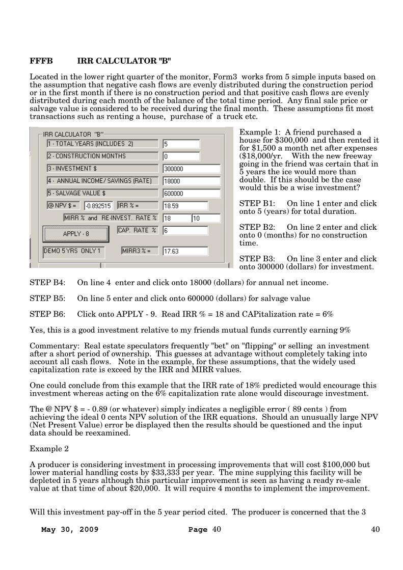
Located in the lower right quarter of the monitor, Form3 works from 5 simple inputs based onthe assumption that negative cash flows are evenly distributed during the construction periodor in the first month if there is no construction period and that positive cash flows are evenlydistributed during each month of the balance of the total time period. Any final sale price orsalvage value is considered to be received during the final month. These assumptions fit mosttransactions such as renting a house, purchase of a truck etc.
Example 1: A friend purchased ahouse for $300,000 and then rented itfor $1,500 a month net after expenses($18,000/yr. With the new freewaygoing in the friend was certain that in5 years the ice would more thandouble. If this should be the casewould this be a wise investment?
STEP B1: On line 1 enter and clickonto 5 (years) for total duration.
STEP B2: On line 2 enter and clickonto 0 (months) for no constructiontime.
STEP B3: On line 3 enter and clickonto 300000 (dollars) for investment.
STEP B4: On line 4 enter and click onto 18000 (dollars) for annual net income.
STEP B5: On line 5 enter and click onto 600000 (dollars) for salvage value
STEP B6: Click onto APPLY - 9. Read IRR % = 18 and CAPitalization rate = 6%
Yes, this is a good investment relative to my friends mutual funds currently earning 9%
Commentary: Real estate speculators frequently "bet" on "flipping" or selling an investmentafter a short period of ownership. This guesses at advantage without completely taking intoaccount all cash flows. Note in the example, for these assumptions, that the widely usedcapitalization rate is exceed by the IRR and MIRR values.
One could conclude from this example that the IRR rate of 18% predicted would encourage thisinvestment whereas acting on the 6% capitalization rate alone would discourage investment.
The @ NPV $ = - 0.89 (or whatever) simply indicates a negligible error ( 89 cents ) fromachieving the ideal 0 cents NPV solution of the IRR equations. Should an unusually large NPV(Net Present Value) error be displayed then the results should be questioned and the inputdata should be reexamined.
Example 2
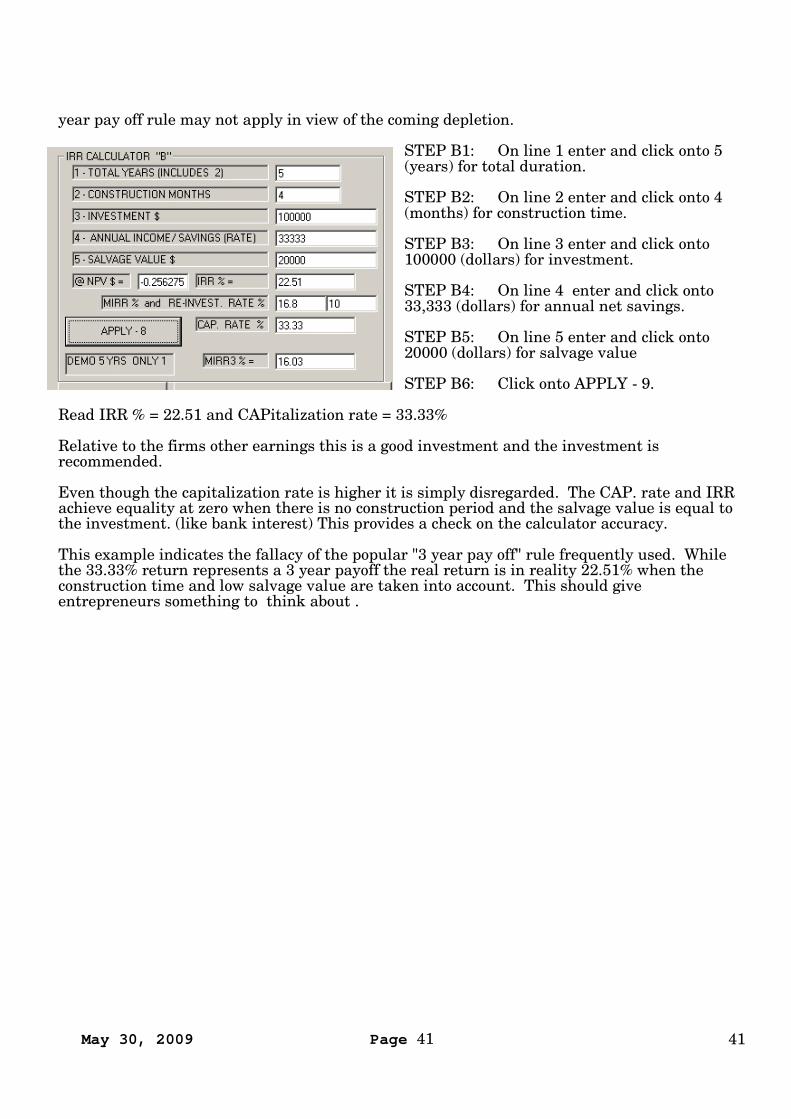
A producer is considering investment in processing improvements that will cost $100,000 butlower material handling costs by $33,333 per year. The mine supplying this facility will bedepleted in 5 years although this particular improvement is seen as having a ready re-salevalue at that time of about $20,000. It will require 4 months to implement the improvement.
Will this investment pay-off in the 5 year period cited. The producer is concerned that the 3
May 30, 2009 Page 41 41
year pay off rule may not apply in view of the coming depletion.
STEP B1: On line 1 enter and click onto 5(years) for total duration.
STEP B2: On line 2 enter and click onto 4(months) for construction time.
STEP B3: On line 3 enter and click onto100000 (dollars) for investment.
STEP B4: On line 4 enter and click onto33,333 (dollars) for annual net savings.
STEP B5: On line 5 enter and click onto20000 (dollars) for salvage value
STEP B6: Click onto APPLY - 9.
Read IRR % = 22.51 and CAPitalization rate = 33.33%
Relative to the firms other earnings this is a good investment and the investment isrecommended.
Even though the capitalization rate is higher it is simply disregarded. The CAP. rate and IRRachieve equality at zero when there is no construction period and the salvage value is equal tothe investment. (like bank interest) This provides a check on the calculator accuracy.
This example indicates the fallacy of the popular "3 year pay off" rule frequently used. Whilethe 33.33% return represents a 3 year payoff the real return is in reality 22.51% when theconstruction time and low salvage value are taken into account. This should giveentrepreneurs something to think about .
May 30, 2009 Page 42 42
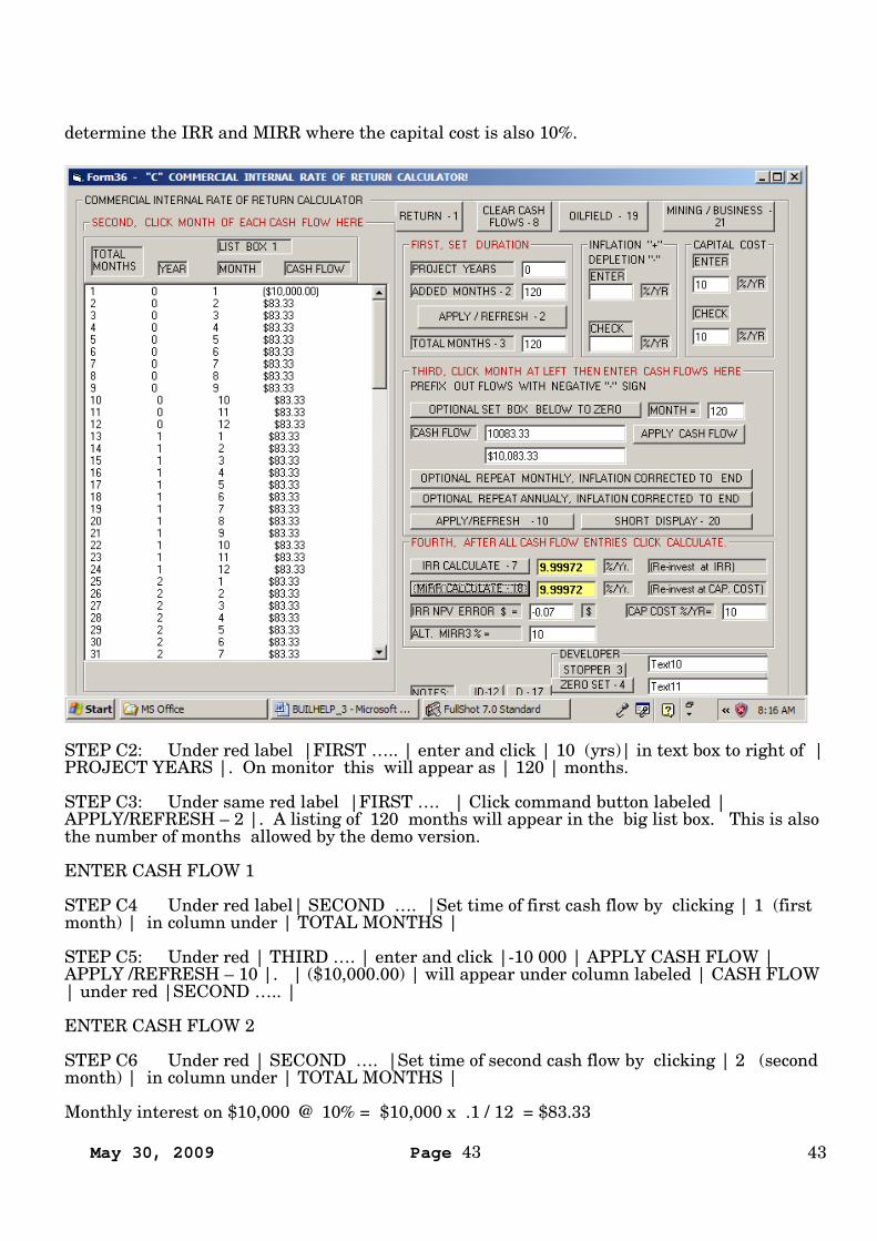
FFFC "C" COMMERCIAL CALCULATOR
This calculator has universal capability for periods up to 100 years. It computes IRR andMIRR directly from previously determined cash flow data yet it retains a surprising simplicityof use
The red labels provide basic direction:
| FIRST, SET DURATION | enter and click a combination of the | PROJECT YEARS | or| ADDED MONTHS | that add up to the total length of time of the project.Clicking |APPLY/REFRESH – 2 | Command button lists each month of project year in biglist box at left.
Under the red label | SECOND, CLICK MONTH OF EACH CASH FLOW HERE | clicknumber of month to which you wish to assign a cash flow.
Near center of form under red label |THIRD, CLICK MONTH AT LEFT THEN ENTERCASH FLOWS HERE | enter and click the amount of each cash flow (in local currency) in thetext box to the right of label | CASH FLOW | Prefix the cash flow amount with a negativesign "-" if the cash flow is an investment or expense. There can be any number of negative cashflows. After entering each cash flow click the command button | APPLY CASH FLOW |located to the far right. After doing this the display in the unlabeled text box immediatelybelow displays the amount in a currency format. If the amount is negative it will be enclosedin parenthetical brackets "()". For convenience you may wish divide each cash flow by onethousand or one million.
Command bars | OPTIONAL REPEAT MONTHLY, INFLATION CORRECTED, TO END |or| OPTIONAL REPEAT YEARLY, INFLATION CORRECTED, TO END | may be clicked torepeat | CASH FLOWS | to end or to an intermediate month or year at which another repeatcommand can be implemented. Optionally applicable to either of these OPTIONAL REPEATcommands is an annual inflation or depletion rate clicked in the |INFLATION DEPLETION|box in the upper right hand corner of Form36. In the case of a monthly REPEAT the interestrate per month is taken as 1/12 the annual rate.
In lower right under red label | FOURTH, AFTER ALL CASH FLOW ENTRIES CLICKCALCULATE | click | CALCULATE - 7 | and | MIRR CALCULATE – 18
Read IRR and MIRR in adjoining list boxes.
While the calculator can accommodate a duration up to 100 years the demo version is limited toexactly 10 years (120 months).
Our example purposely demonstrates a known result. We invest $10,000 during month 1 andthen draw, starting with month 2, a 10% annual return at the rate of $83.33 per month.($83.33 times 12 = $1,000 or 10% (read 9.99972%) of the initial investment). On the final or120th month we get our money back plus the final return or $10,083.33. (Program obtainsessentially the same result (9.68904%) by drawing $1,000 annually and $11,000 final totalreturn. The slightly lower IRR reflects the time delay of annualized positive cash flows. (Somecall it a shift in the center of gravity of cash flows) The capitalization rate would also be 10%This teaching example enables a proof check of calculator accuracy at the same time. Any orall of the CASH FLOWS listed in the LIST BOX can be edited to reflect different and variablecircumstances.
Now let's go through the procedure of actually entering the data.
STEP C1: Near upper right of Form36 click command button "CLEAR CASH FLOWS - 8".
For an example to check accuracy we will use a 10% return from a $10,000 investment to
May 30, 2009 Page 43 43
determine the IRR and MIRR where the capital cost is also 10%.
STEP C2: Under red label |FIRST ….. | enter and click | 10 (yrs)| in text box to right of |PROJECT YEARS |. On monitor this will appear as | 120 | months.
STEP C3: Under same red label |FIRST …. | Click command button labeled |APPLY/REFRESH – 2 |. A listing of 120 months will appear in the big list box. This is alsothe number of months allowed by the demo version.
ENTER CASH FLOW 1
STEP C4 Under red label| SECOND …. |Set time of first cash flow by clicking | 1 (firstmonth) | in column under | TOTAL MONTHS |
STEP C5: Under red | THIRD …. | enter and click |-10 000 | APPLY CASH FLOW |APPLY /REFRESH – 10 |. | ($10,000.00) | will appear under column labeled | CASH FLOW| under red |SECOND ….. |
ENTER CASH FLOW 2
STEP C6 Under red | SECOND …. |Set time of second cash flow by clicking | 2 (secondmonth) | in column under | TOTAL MONTHS |
Monthly interest on $10,000 @ 10% = $10,000 x .1 / 12 = $83.33

May 30, 2009 Page 44 44
STEP C7: Under red | THIRD …. | enter and click |83.33 | APPLY CASH FLOW |OPTIONAL REPEAT MONTHLY, INFLATION CORRECTED TO END | APPLY / REFRESH– 10 |
$83.33 will appear under column labeled | CASH FLOW | under red |SECOND ….. | at eachmonth.
STEP C8: Return $10,000 to investor at end of 10 year period. Click month | 120 | underred label | SECOND, …………. |
STEP C9: Under red label | THIRD ,……… | in text box labeled | CASH FLOW | enterand click | 10083.33 | APPLY CASH FLOW | APPLY / REFRESH |
Note: The initial investment is returned plus the monthly interest for the 120th month.
STEP C10: Under the red label | FOURTH | click | IRR CALCULATE – 7 | MIRRCALCULATE – 18 |
The final results are seen in adjoinning text boxes. IRR = 9.99972% and MIRR = 9.99972%very close to the theoretical 10%.
May 30, 2009 Page 45 45
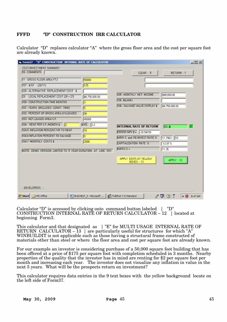
FFFD "D" CONSTRUCTION IRR CALCULATOR
Calculator “D” replaces calculator “A” where the gross floor area and the cost per square footare already known.
Calculator “D” is accessed by clicking onto command button labeled | "D"CONSTRUCTION INTERNAL RATE OF RETURN CALCULATOR – 12 | located atbeginning Form3.
This calculator and that designated as | "E" for MULTI USAGE INTERNAL RATE OFRETURN CALCULATOR – 13 | are particularly useful for structures for which "A"WINBUILDIT is not applicable such as those having a structural frame constructed ofmaterials other than steel or where the floor area and cost per square foot are already known.
For our example an investor is considering purchase of a 50,000 square foot building that hasbeen offered at a price of $175 per square foot with completion scheduled in 3 months. Nearbyproperties of the quality that the investor has in mind are renting for $2 per square foot permonth and increasing each year. The investor does not visualize any inflation in value in thenext 5 years. What will be the prospects return on investment?
This calculator requires data entries in the 9 text boxes with the yellow background locate onthe left side of Form37.
May 30, 2009 Page 46 46
STEP D1: At | 11 – GROSS FLOOR AREA FT2 | enter and click | 50 000 |
STEP D2: At | 107 - $/SF – (29/11) | enter and click |175 |.
STEP D3: At | 100 – CONSTRUCTION TIME MONTHS | Enter and click | 3 |.
STEP D4: At | 101 – Years (INCLUDES CONST TIME) | Enter and click | 5 |.
STEP D5: At | 102 – PERCENT OF GROSS AREA (11} LEASED | Enter and click | 90 |
STEP D6: At | 104 - RENT PER S.F./MONTH$ | Enter and click | 2 |
STEP D7: At | 104.5 - INFLATION PERCENT/YR TO RENT | Enter and click |10 |
This used to develop the average rent listed in the white box to the right of line 104.
STEP D8: At | 104.6 INFLATION PERCENT TO SALVAGE | Enter and click | 0 |
This percent increase is applied to | 29 LOCAL REPLACEMENT COST |
STEP D9: Click | APPLY EDITS AT YELLOW BOXES – 13 |
STEP D10: Click | APPLY – 12 |
INTERNAL RATE OF RETURN = 11.8%MODIFIED INTERNAL RATE OF RETURN = 11.35%CAPITALIZATION RATE = 12.07%
The investor should use the least of these.
May 30, 2009 Page 47 47
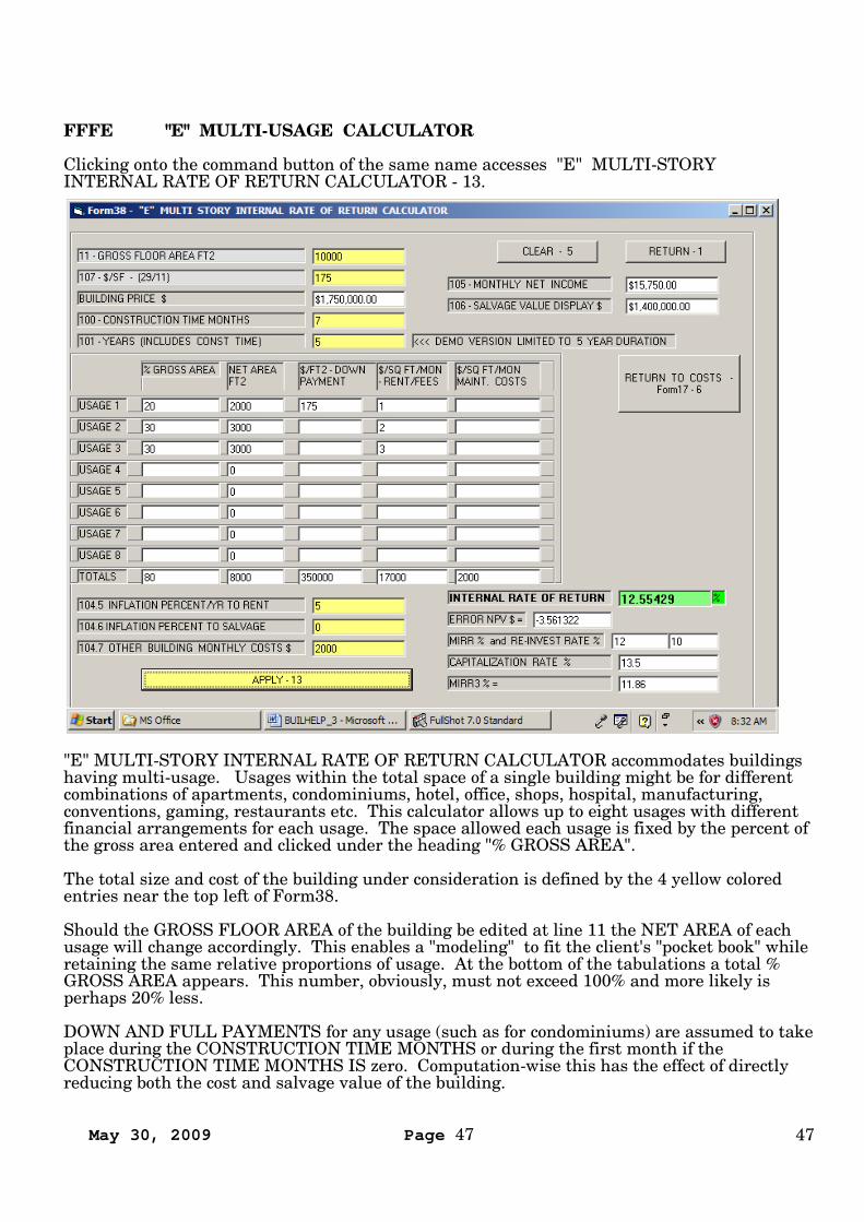
FFFE "E" MULTI-USAGE CALCULATOR
Clicking onto the command button of the same name accesses "E" MULTI-STORYINTERNAL RATE OF RETURN CALCULATOR - 13.
"E" MULTI-STORY INTERNAL RATE OF RETURN CALCULATOR accommodates buildingshaving multi-usage. Usages within the total space of a single building might be for differentcombinations of apartments, condominiums, hotel, office, shops, hospital, manufacturing,conventions, gaming, restaurants etc. This calculator allows up to eight usages with differentfinancial arrangements for each usage. The space allowed each usage is fixed by the percent ofthe gross area entered and clicked under the heading "% GROSS AREA".
The total size and cost of the building under consideration is defined by the 4 yellow coloredentries near the top left of Form38.
Should the GROSS FLOOR AREA of the building be edited at line 11 the NET AREA of eachusage will change accordingly. This enables a "modeling" to fit the client's "pocket book" whileretaining the same relative proportions of usage. At the bottom of the tabulations a total %GROSS AREA appears. This number, obviously, must not exceed 100% and more likely isperhaps 20% less.
DOWN AND FULL PAYMENTS for any usage (such as for condominiums) are assumed to takeplace during the CONSTRUCTION TIME MONTHS or during the first month if theCONSTRUCTION TIME MONTHS IS zero. Computation-wise this has the effect of directlyreducing both the cost and salvage value of the building.
May 30, 2009 Page 48 48
Revenue to the building owner, which takes place after the CONSTRUCTION TIME, is enteredunder the column heading $/SQ FT/MON - RENT/FEES. In the case of a condominium this issometimes called an "Association Fee".
Costs to the building owner that can be expressed in terms of $/SQ FT/MON MAINT COSTSmay be entered in the 5th column of that heading name at the appropriate usage
Blanket costs to the buildings owner that are known can be entered as total dollars at linenumber 104.7.
Inflation per year applicable as a percent to rental amounts (as an average rental rate) may beentered at line 104.5
Expected inflation of net value of building (less down and/or full payments) to time of final saleor salvage may be entered at line 104.6. (Keep in mind that a 100% doubles the price, 200%triples, 300% quadruples etc)
Read line 106 near far upper right to ensure program reads what you have in mind for finalsale price.With the foregoing data entered determining IRR and CAPITALIZATION RATE isaccomplished by clicking APPLY - 13.
Results will appear adjoining label INTERNAL RATE OF RETURN and CAPITALIZATIONRATE.
A small investor aged 60 is considering acquiring a small multi-use building presently underconstruction but retirement plans dictate selling it at age 65. The price is $175/ft all inclusive.Availability for occupancy will be in 7 months. Indications are that rental rates in thisneighborhood will increase 5% per year and that in 10 years when the college is completednearby the price should quadruple (300%).
STEP E1: At | 11 – GROSS FLOOR AREA FT2 | enter and click | 10 000 |
STEP E2: At | 107 - $/SF – (29/11) | enter and click | 175 |
STEP E3: At | 100 CONSTRUCTION TIME MONTHS | enter and click |7 |
STEP E4: At | 101 – YEARS (INCLUDES CONST TIME) enter and click | 5 |.
NOTE 1: To raise additional money investor plans to sell 20% of space as condominiums andcharge 1 ($/SQ FT/MON) as Association fee.
STEP E5: At |USAGE 1 | under | % GROSS AREA | enter and click | 20 |
STEP E6: At |USAGE 1 | under | $/FT2 - DOWN PAYMENT | enter and click |175 |.
STEP E7: At | USAGE 1 | under | $/SQ FT/MON - RENT/FEES | enter and click | 1 |
NOTE 2: Investor plans to rent 30% of space as apartments and charge 2 $/SQ FT/MON asrent.
STEP E8: At |USAGE 2 | under |% GROSS AREA | enter and click | 30 |
STEP E9: At | USAGE 2 | under |$/SQ FT/MON RENT/FEES | enter and click | 2 |.
NOTE 3: Investor plans to rent 30% of space to a clothing store chain for 3 $/SQ FT/MON.
May 30, 2009 Page 49 49
STEP E10: At | USAGE 3 | under |% GROSS AREA | enter and click | 30 |
STEP E11: At | USAGE 3 | under |$/SQ FT/MON RENT/FEES | enter and click | 3 |
STEP E12: At |104.5 INFLATION PERCENT/YR TO RENT | enter and click |5 |
Note: Investor foresees $2,000 additional monthly maintenance costs.
STEP E13: At | 104.6 INFLATION PERCENT TO SALVAGE | enter and click | 0 |
STEP E14: At | 104.7 OTHER BULDING MONTHLY COSTS | enter and click | 2000 |
STEP E14: Click | APPLY – 13 |
STEP E16: Read
| INTERNAL RATE OF RETURN | = 12 % and| CAPITALIZATION RATE | = 13.5%|MODIFIED INTERNAL RATE OF RETURN | = 11%
COMMENTARY: Through modeling investor concludes that actual IRR will range between alow of 12.5% and a higher value of 36% Since both of these values are higher than his otherinvestments the Investor elected to go ahead.
May 30, 2009 Page 50 50
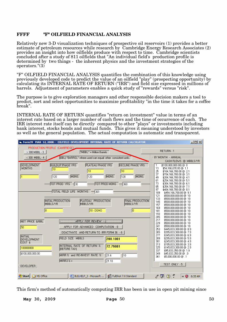
FFFF "F" OILFIELD FINANCIAL ANALYSIS
Relatively new 3-D visualization techniques of prospective oil reservoirs (1) provides a betterestimate of petroleum resources while research by Cambridge Energy Research Associates (2)provides an insight into how oilfields produce with respect to time. Cambridge scientistsconcluded after a study of 811 oilfields that "An individual field's production profile isdetermined by two things - the inherent physics and the investment strategies of theoperators."(3)
"F" OILFIELD FINANCIAL ANALYSIS quantifies the combination of this knowledge usingpreviously developed code to predict the value of an oilfield "play" (prospecting opportunity) bycalculating its INTERNAL RATE OF RETURN ("IRR") and field size expressed in millions ofbarrels. Adjustment of parameters enables a quick study of "rewards" versus "risk".
The purpose is to give exploration managers and other responsible decision makers a tool topredict, sort and select opportunities to maximize profitability "in the time it takes for a coffeebreak".
INTERNAL RATE OF RETURN quantifies "return on investment" value in terms of aninterest rate based on a larger number of cash flows and the time of occurrence of each. TheIRR interest rate itself can be directly compared to other "plays" or investments includingbank interest, stocks bonds and mutual funds. This gives it meaning understood by investorsas well as the general population. The actual computation is automatic and transparent.
This firm's method of automatically computing IRR has been in use in open pit mining since
May 30, 2009 Page 51 51
1990.
OILFIELD ANALYSIS, DEMO
STEP F1: At |Form3 | click | "F" OILFIELD - 15| l lower right quarter.
STEP F2: At Form36 click | "OILFIELD - 19 | upper right quarter.
STEP F3: At Form39 click | TEST ONLY - 5 | command button located bottom right..
STEP F4: Click | APPLY FOR REVIEW – 2 | command button located near center of form.
STEP F5: Read IRR and field size near bottom of form. Then try editing any of the light yellowtext boxes and then repeat F above. From there "wing-it"
STEP F6: Click command bar | APPLY FOR ADVANCED COMPUTATION - 8 | nearenter of form. This command displays the same data as editable cash flows on Form36.Click | APPLY/ REFRESH | near lower right for output data. This procedure enablesintroduction of other cash flows, such as those for extended drilling operations, basedon time of occurrence. For further instructions on the use of this form review | “C”COMMERCIAL INTERNAL RATE OF RETURN CALCULATOR |
May 30, 2009 Page 52 52
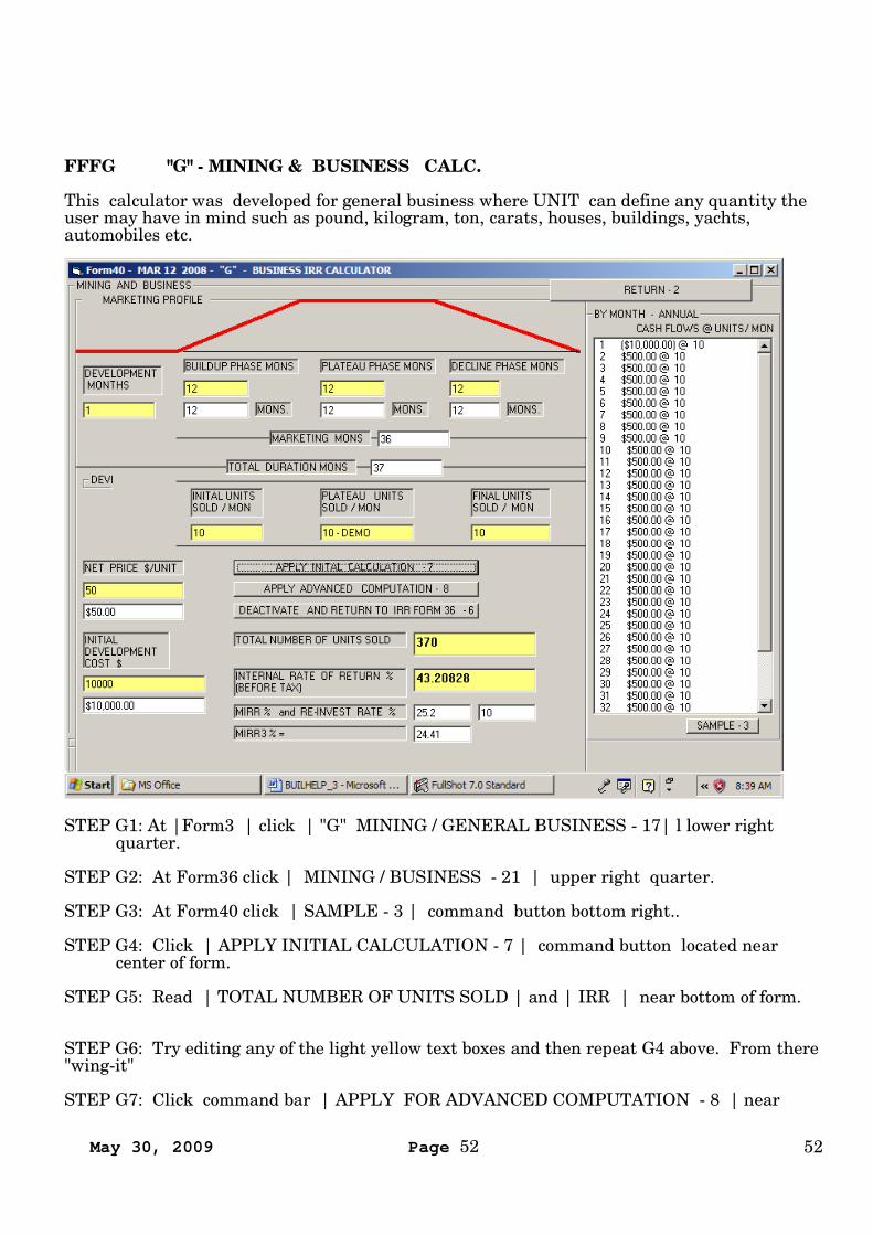
FFFG "G" - MINING & BUSINESS CALC.
This calculator was developed for general business where UNIT can define any quantity theuser may have in mind such as pound, kilogram, ton, carats, houses, buildings, yachts,automobiles etc.
STEP G1: At |Form3 | click | "G" MINING / GENERAL BUSINESS - 17| l lower rightquarter.
STEP G2: At Form36 click | MINING / BUSINESS - 21 | upper right quarter.
STEP G3: At Form40 click | SAMPLE - 3 | command button bottom right..
STEP G4: Click | APPLY INITIAL CALCULATION - 7 | command button located nearcenter of form.
STEP G5: Read | TOTAL NUMBER OF UNITS SOLD | and | IRR | near bottom of form.
STEP G6: Try editing any of the light yellow text boxes and then repeat G4 above. From there"wing-it"
STEP G7: Click command bar | APPLY FOR ADVANCED COMPUTATION - 8 | near

May 30, 2009 Page 53 53
enter of form. This command displays the same data as editable cash flows on Form36.Click | APPLY/ REFRESH | near lower right for output data. This procedure enablesintroduction of other cash flows, such as those for extended drilling operations, based on timeof occurrence. For further instructions on the use of this form review | “C” COMMERCIALINTERNAL RATE OF RETURN CALCULATOR |
May 30, 2009 Page 54 54
APPEN APPENDIX
(1)Dr Jeremy HallEarth Sciences Dept.Memorial UniversitySt. Johns, NewfoundlandA1B 3X5, Canada
(2)Cambridge Energy Research Associates55 Cambridge ParkwayCambridge, MA 02142
(3)The Wall Street Journal, February 2, 2008
CONTACT:
Tel 661 871 2168 - Fax 661 871 1798 - Cell 661 809 4764 www.winbuildit.comCREATIVE ENGINEERING USA3513 Century DriveBakersfield, CA 93306 1238
END OF DOCUMENT
Developers Notes:
Original:
C:\AA\BUILDOC\BUILHELP_3.DOC 5/30/2009 6:47 AM


![Estimating and interpreting structural equation models … · Estimating and interpreting structural equation models in Stata 12 ... and Var [ǫ] = Σ sem (y1 ... Structural equation](https://img.pdfslide.us/doc/110x75/5b286e167f8b9ae8108b4592/estimating-and-interpreting-structural-equation-models-estimating-and-interpreting.jpg)