Embed Size (px)
Citation preview

Abstract—The STEP Cube Lab (Cube Laboratory for Space
Technology Experimental Projects) is a 1U cube satellite
developed by the Space Technology Synthesis Laboratory of
Chosun University to be launched in 2015. Its mission objective
is twofold: to determine which of the fundamental space
technologies researched at domestic universities, will be
potential candidates for use in future space missions and to
verify the effectiveness of the technologies by investigating
mission data obtained from on-orbit operation of the cube
satellite. In this paper, a structural design concept based on the
1U standard to achieve the mission objective is introduced. The
validity of the design has been demonstrated by quasi-static
analysis and modal analysis. In addition, a non-explosive
separation device triggered by burn wire heating, which is one
of the main mission payloads is introduced.
Index Terms—CubeSat, pico-class satellite, structural design,
non-explosive separation mechanism.
I. INTRODUCTION
The program of pico-class satellites called CubeSats
started in 1999 at the space systems development laboratory
(SSDL) at Stanford University under the leadership of Robert
J. Twiggs [1]. The main purpose of CubeSats is to make space
science and technology readily accessible to students,
engineers, and even to some governments at a fraction of the
design, build, and launch costs of standard satellite projects
[2]. The main features of the CubeSat is 10 cm×10 cm×10 cm
in volume and less than 1.33 kg in mass based on the 1U
CubeSat standard.
The STEP Cube Lab (Cube Laboratory for Space
Technology Experimental Project) is the first pico-class
satellite developed at the STSL (Space Technology Synthesis
Laboratory) at Chosun University, and is scheduled to be
launched in 2015. The main mission objective of the STEP
Cube Lab is twofold: to determine which fundamental space
technologies researched at domestic universities, will be
potential candidates for future space missions and to verify
the effectiveness of these technologies by investigating
mission data obtained from on-orbit operation of the cube
satellite. The function and performance of these technologies
have been previously verified by laboratory-level research at
Manuscript received January 27, 2014; revised March 24, 2014. This
research was supported by Space Core Technology Development Program
through the National Research Foundation of Korea funded by the Ministry
of Science, ICT & Future Planning.
The authors are with the Department of Aerospace Engineering, Chosun
University (e-mail: [email protected], [email protected],
universities, but their design effectiveness has never been
qualified in environment of outer space or in some cases,
on-ground simulated space environment. Therefore, we
cannot guarantee that these technologies will operate without
any malfunction in an on-orbit environment although they
showed stable function during laboratory-level tests. The
STEP mission makes it possible to perform on-orbit
verification of five technologies using a 1U CubeSat. The
payloads to be verified in the STEP mission are a variable
emittance radiator, an oscillating heat pipe, a MEMS based
solid propellant thruster, a concentrating photovoltaic (CPV)
power system, and a novel non-explosive holding and release
mechanism triggered by nichrome burn wire heating.
In this paper, we focus on the non-explosive holding and
release mechanism triggered by a nichrome burn wire, which
is one of the main payloads to be verified in the STEP mission,
because it is most closely related to the mechanical design.
This mechanism will be applied to achieve synchronous
release of multi-deployable communication antennas using a
single mechanism in the STEP mission. The mechanism has
the advantage of negligible induced shock and greater load
capability than conventional nylon cable cutting mechanisms
[3] that are generally used in cube satellite applications. This
mechanism also enables synchronous release of multiple
deployable structures when an appropriate implementation
method is used.
A pyro technic device [4] is also a candidate for complex
cube missions in which greater load capability is required.
However, usage of pyrotechnic devices in a cube satellite may
cause problems because the external and internal parts are in
closer physical proximity to the source of shock in a cube
satellite than in larger commercial satellites, owing to the
extremely small size and volume of a cube satellite.
Additionally, the cube satellite requirements do not permit the
use of explosive pyrotechnic devices.
Several types of non-explosive separation device using
shape memory alloys [5] have been developed and used in
space missions. The advantages of the non-explosive
actuators are lower shock, greater load capability, and
reusability for additional cycles after a simple reset. However,
even though the shock level is low, use of these devices in
cube satellites may nevertheless be limited because of their
high cost and the fact that they do not meet the typical
pico-satellite requirements of low weight, small size, and
generating relatively small shocks. The high cost of these
devices makes them impractical to use on cube satellites that
have development cost limitations.
In this study, a structural design concept of the STEP Cube
Structural Design and Analysis of 1U Standardized
STEP Cube Lab for On-Orbit Verification of Fundamental
Space Technologies
Hyun-Ung Oh, Su-Hyeon Jeon, and Seong-Cheol Kwon
International Journal of Materials, Mechanics and Manufacturing, Vol. 2, No. 3, August 2014
239DOI: 10.7763/IJMMM.2014.V2.135

Lab to achieve the mission objectives is proposed and
investigated. The design concept is based on a standardized
1U cube design, and it will fly a number of payloads for
on-orbit verification of technology for future missions. For
the 1U CubeSat design, it is very important to achieve an
efficient lightweight satellite configuration under the
constraints of limited volume. The structural design combined
with a novel non-explosive holding and release mechanism
used for synchronous release of multi-deployable antennas is
described in this paper. The effectiveness of the structural
design has been verified using quasi-static and modal analysis.
In addition, the margin of safety for the PCBs with respect to
the estimated allowable deflection has been investigated
based on fatigue failure theory.
II. STEP MISSION PAYLOADS AND FEATURES OF THE
NON-EXPLOSIVE HOLD AND RELEASE MECHANISM
In general, owing to the high development cost of space
qualification of research output, research on advanced space
technologies for future missions performed at universities is
limited to theoretical works and laboratory-level research
without consideration of the space environment. Therefore,
the main mission objectives of the STEP Cube Lab are to
identify core space technologies researched in industries or
universities, and to verify these technologies on-orbit.
Table I summarizes the payload candidates to be verified in
the STEP mission. The MEMS solid propellant thruster [6]
comprises a micro-nozzle, a micro-igniter, a glass membrane,
a propellant chamber, and a solid propellant. The average
values of the maximum thrust and total impulse are 3619 mN
and 0.381 mNs, respectively. The thruster is suitable for cube
satellite applications because it consumes less than 300mW
for ignition of the solid propellant.
Variable emittance radiators [7] based on the
metal-insulator transition of (La,Sr)MnO3 thin films have
been developed. The (La,Sr)MnO3 thin films have low
emittance at low temperature and high emittance at high
temperature. Moreover, the emittance significantly changes at
the metal-insulator transition temperature, at which the
material changes from a highly reflective metal into a less
reflective insulator. Therefore, in the case of the lowest
temperature, the radiator does not require additional heater
power to keep the electronics within the allowable
non-operating cold temperature.
Commonly used heat pipes, which achieve promising heat
transfer performance using surface tension and capillary
action, experience performance degradation during ground
test due to the gravity effect when the heat pipes are inclined.
To overcome the disadvantages of conventional heat pipes,
oscillating heat pipes [8] have been proposed and investigated.
Oscillating heat pipes uses the phenomenon of self-sustaining
oscillatory flow of working fluid. Heat is transferred in the
liquid-vapor circulation cycle between the heating section and
the cooling section as latent heat. Therefore, particularly
regarding ground tests, oscillating heat pipes are useful in
satisfying the mechanical design constraints of satellites
because the performance degradation of the heat pipe due to
gravity can be minimized.
A CPV power system [9] is a photovoltaic power
generation system that uses a small generating device to
convert energy from high intensity light from the sun that has
been concentrated by a lens array system. CPV systems have
been widely used for ground applications because there is no
restriction on the size of the lens system. However, CPV
technology has not been considered for space applications
although effective power generation is expected. Therefore,
we focus on a CPV system for cube satellite applications that
uses a MEMS based lens array system. This system has the
potential to increase power generation when the angle
between the sunlight and the solar cell is zero by effectively
concentrating solar energy on solar panels.
TABLE I: PAYLOADS OF STEP CUBE LAB
Payload Configuration Payload Configuration
MEMS
Solid
Propellant
Thruster
Oscillating
Heat pipe
Variable
Emittance
Radiator
MEMS
CPV
System
*Non-explosive holding and release mehcanism is described in Fig. 1
Recently, cube satellites have been used for increasingly
complex missions. Considering their extremely small package
size, the range of functions that they can perform gives rise to
the use of numerous mechanisms and deployable structures
that are necessary for achieving challenging mission-related
functions. The cube satellite architecture also requires that
deployable structures, such as solar arrays, antennas, and
other appendages, are stowed for launch, and released and
deployed in orbit for operation. To hold and release
deployable appendages of a cube satellite, a nichrome burn
wire release mechanism has typically been used owing to its
advantages of being simple, reliable, and inexpensive.
However, if we apply this conventional mechanism to
applications with multi-deployable appendages, the systems
of a cube satellite may be complicated by the many nichrome
burn wire release mechanisms required for holding
multi-deployable structures. The conventional mechanism
using nylon wire also has drawbacks such as complexity and
low constraint force. To overcome these drawbacks, we
developed a non-explosive holding and release mechanism
based on the nylon cutting method as one of the payloads for
the STEP missions. This mechanism was designed for high
load capacity, negligible shocks, and synchronous release of
multi-deployable structures. Figure 1 shows both the stowed
and released configurations of the non-explosive separation
mechanism. The mechanism consists of a constraint bolt, two
segmented nuts, a pin, a nylon cable, and two springs. Both
springs are compressed inside of the separation nut, and this
nut is constrained by winding the nylon cable around it. The
nut is released by triggering the nichrome burn wire. When
the nichrome burn wire is heated, the nylon cable wound
around the integrated nut is cut, and the nut is immediately
separated by the restoration force of the two springs, as shown
International Journal of Materials, Mechanics and Manufacturing, Vol. 2, No. 3, August 2014
240
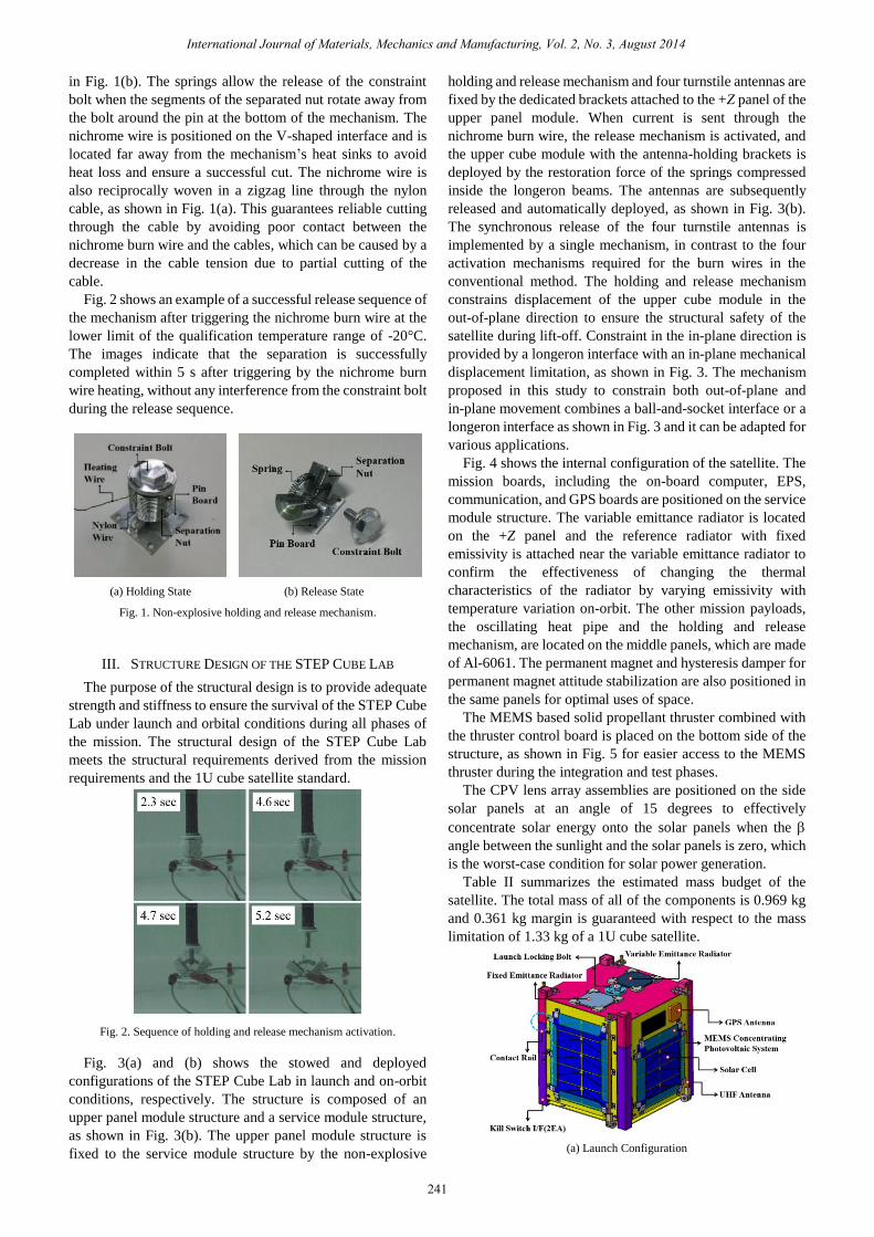
in Fig. 1(b). The springs allow the release of the constraint
bolt when the segments of the separated nut rotate away from
the bolt around the pin at the bottom of the mechanism. The
nichrome wire is positioned on the V-shaped interface and is
located far away from the mechanism’s heat sinks to avoid
heat loss and ensure a successful cut. The nichrome wire is
also reciprocally woven in a zigzag line through the nylon
cable, as shown in Fig. 1(a). This guarantees reliable cutting
through the cable by avoiding poor contact between the
nichrome burn wire and the cables, which can be caused by a
decrease in the cable tension due to partial cutting of the
cable.
Fig. 2 shows an example of a successful release sequence of
the mechanism after triggering the nichrome burn wire at the
lower limit of the qualification temperature range of -20°C.
The images indicate that the separation is successfully
completed within 5 s after triggering by the nichrome burn
wire heating, without any interference from the constraint bolt
during the release sequence.
(a) Holding State (b) Release State
Fig. 1. Non-explosive holding and release mechanism.
III. STRUCTURE DESIGN OF THE STEP CUBE LAB
The purpose of the structural design is to provide adequate
strength and stiffness to ensure the survival of the STEP Cube
Lab under launch and orbital conditions during all phases of
the mission. The structural design of the STEP Cube Lab
meets the structural requirements derived from the mission
requirements and the 1U cube satellite standard.
Fig. 2. Sequence of holding and release mechanism activation.
Fig. 3(a) and (b) shows the stowed and deployed
configurations of the STEP Cube Lab in launch and on-orbit
conditions, respectively. The structure is composed of an
upper panel module structure and a service module structure,
as shown in Fig. 3(b). The upper panel module structure is
fixed to the service module structure by the non-explosive
holding and release mechanism and four turnstile antennas are
fixed by the dedicated brackets attached to the +Z panel of the
upper panel module. When current is sent through the
nichrome burn wire, the release mechanism is activated, and
the upper cube module with the antenna-holding brackets is
deployed by the restoration force of the springs compressed
inside the longeron beams. The antennas are subsequently
released and automatically deployed, as shown in Fig. 3(b).
The synchronous release of the four turnstile antennas is
implemented by a single mechanism, in contrast to the four
activation mechanisms required for the burn wires in the
conventional method. The holding and release mechanism
constrains displacement of the upper cube module in the
out-of-plane direction to ensure the structural safety of the
satellite during lift-off. Constraint in the in-plane direction is
provided by a longeron interface with an in-plane mechanical
displacement limitation, as shown in Fig. 3. The mechanism
proposed in this study to constrain both out-of-plane and
in-plane movement combines a ball-and-socket interface or a
longeron interface as shown in Fig. 3 and it can be adapted for
various applications.
Fig. 4 shows the internal configuration of the satellite. The
mission boards, including the on-board computer, EPS,
communication, and GPS boards are positioned on the service
module structure. The variable emittance radiator is located
on the +Z panel and the reference radiator with fixed
emissivity is attached near the variable emittance radiator to
confirm the effectiveness of changing the thermal
characteristics of the radiator by varying emissivity with
temperature variation on-orbit. The other mission payloads,
the oscillating heat pipe and the holding and release
mechanism, are located on the middle panels, which are made
of Al-6061. The permanent magnet and hysteresis damper for
permanent magnet attitude stabilization are also positioned in
the same panels for optimal uses of space.
The MEMS based solid propellant thruster combined with
the thruster control board is placed on the bottom side of the
structure, as shown in Fig. 5 for easier access to the MEMS
thruster during the integration and test phases.
The CPV lens array assemblies are positioned on the side
solar panels at an angle of 15 degrees to effectively
concentrate solar energy onto the solar panels when the
angle between the sunlight and the solar panels is zero, which
is the worst-case condition for solar power generation.
Table II summarizes the estimated mass budget of the
satellite. The total mass of all of the components is 0.969 kg
and 0.361 kg margin is guaranteed with respect to the mass
limitation of 1.33 kg of a 1U cube satellite.
(a) Launch Configuration
International Journal of Materials, Mechanics and Manufacturing, Vol. 2, No. 3, August 2014
241

(b) Deployed Configuration On-orbit
Fig. 3. STEP Cube lab configuration.
Fig. 4. Internal configuration of STEP Cube lab.
Fig. 5. MEMS thruster location.
TABLE II: MASS BUDGET OF STEP CUBE LAB
Components Mass (kg)
Structure 0.32
Mechanism 0.019
Electronic Boards 0.368
AOCS 0.035
Payloads 0.156
Etc. 0.071
Total Mass 0.969
Margin (w.r.t. Req. of 1.33kg) 0.361
IV. STRUCTURAL ANALYSIS AND RESULTS SUMMARY
To confirm the effectiveness of the structural design of the
1U cube satellite STEP Cube Lab, quasi-static analysis to
confirm the margin of safety with respect to the design load,
modal analysis to confirm that the frequency requirement was
satisfied, and PCB analysis to confirm the margin of safety
with respect to the allowable deflection of the PCBs were
performed using a simplified finite element model (FEM) as
shown in Fig. 6.
For the analysis, MSC Patran software was used for pre-
and post-processing and MSC-Nastran was employed as a
solver. Table III summarizes the material properties used in
the analysis. The frame structures of the primary structure of
the cube satellite are modeled by using 1D beam elements.
The PCB connections are also modeled using 1D beam
elements. Shell elements were used to represent each of the
structure panels, the PCBs, the MEMS concentrating lens,
and the MEMS thruster. The non-explosive holding and
release mechanism was modeled using spring elements with
an axial stiffness of 4170 N/mm, based on a static test. In the
analysis, rigid boundary conditions were applied at the
bottom sides of the beam structures.
(a) Primary Structure
(b) PCBs
Fig. 6. FEM of STEP Cube lab.
TABLE III: MATERIAL PROPERTIES
To verify compliance with the frequency requirement, we
performed a modal analysis. The required first eigen
frequency for frequency separation during launch is larger
than 100 Hz. The modal analysis results are summarized in
Table IV, and the mode shapes of interest are shown in Fig. 7.
The calculated the first eigen frequency is 155 Hz for the
bending mode of the PCB modules, as shown in Fig. 7, which
is greater than the requirement of 100 Hz. The modes until
twelve modes are observed from the local modes of the PCBs.
The modes of involving the CPV lens array module occurred
at a frequency of 622.85 Hz, and is well decoupled from the
eigen frequency of approximately 1000 Hz of the primary
structural mode of the longeron beams, although this is not
Density
(kg/m3)
Yong’s
Modulus
(GPa)
Poisson’s
Ratio
Yield
Stress
(MPa)
Ultimate
Stress
(MPa)
PCB
(Polyimide) 1850 18.37 0.136 - 242
Structure
(Al6061-T6) 2700 68.9 0.33 276 310
CPV,
MEMS
Thruster
(Glass)
2370 77.8 0.22 70 70
International Journal of Materials, Mechanics and Manufacturing, Vol. 2, No. 3, August 2014
242

shown here because the CPV lens system is directly integrated
into the longeron beams through the solar panels.
To investigate structural safety under the launch
environment, we performed a quasi-static analysis. For this
analysis, we applied a design load of g = 42.3 G derived from
the qualification level of a random vibration of 14.1 Grms , as
shown in the following equation.
14.1 3g Grms (1)
To investigate structural safety, we applied the following
MoS (Margin of Safety) rule with a safety factor of 1.25.
allowable
max
1 0MoSSF
(2)
Here, allowable is the allowable strength,
max is calculated
strength and SF is the safety factor. For the PCB and the
glass materials, safety factors of 1.4 and 2 were applied in the
analysis, respectively. Table V summarizes the maximum
stress and MoS at each axis under a quasi-static load of 42.3 G.
The analysis results indicated sufficient margins in all cases
and in all directions. The CPV system also showed a positive
margin in all directions, although it is brittle material with a
low allowable strength compared to other parts.
TABLE IV: MODAL FREQUENCIES
Mode Frequency
(Hz)
Zone of
Interest Mode
Frequency
(Hz)
Zone of
Interest
1 155.21 PCB 8 521.4 PCB
2 161.1 PCB 9 593.85 PCB
3 271.22 PCB 10 600.02 PCB
4 275.2 PCB 11 610.4 PCB
5 283.53 PCB 12 616 PCB
6 331.04 PCB 13 619.25 MEMS
Thruster
7 435.17 PCB 14 622.85 CPV
To investigate the structural safety of the PCB electronics
under the launch environment, we performed PCB analysis
based on fatigue failure theory. Figure 8 shows an example of
the EPS board configuration considered in the analysis. The
allowable deflection of the PCB is calculated using following
equation (3) and the PCB configuration shown in Fig. 8.
allowable 0.5
0.0028d
Ctrl (3)
Here, d is the length of the PCB edge parallel to the
component, C is the coefficient of chip configuration, t is
thickness of the PCB, l is the length of the component, and r is
derived from the component’s position [10]. To investigate
structural safety, we applied the following MoS rule with a
safety factor of 1.4.
allowable
max
1 0MoSSF
(4)
Here, allowable is the allowable deflection,
max is the
calculated maximum deflection, and SF is the safety factor.
Table IV summarizes the MoS results for the PCBs with
respect to their maximum allowable deflection of PCBs. The
analysis results indicate that all cases showed positive
margins in the critical axis of z from a PCB structural safety
point of view. The analysis results indicate that the structure
design of 1U standardized STEP Cube Lab guarantees
structural safety in the launch environment.
(a) 1st Mode (b) 13th Mode
(c) 14th Mode
Fig. 7. Mode shape.
TABLE V: QUASI-STATIC ANALYSIS RESULT SUMMARY
Max Stress (MPa)
SF Margin of Safety
x y z x y z
PCB 18.3 16.7 6.51 1.40 8.45 9.35 25.6
Structure 20.6 18.9 2.82 1.25 9.72 10.7 77.3
CPV
System 6.0 6.06 1.97 2.0 4.83 4.78 16.8
MEMS
Thruster 0.17 0.17 2.26 2.0 205 205 14.5
TABLE VI: PCB ANALYSIS RESULTS SUMMARY
Fig. 8. EPS Board configuration.
(C=1.26, t=1.6mm, r=0.8mm, l=11.6mm, d=90mm)
PCB max (mm) allowable (mm) MoS
EPS 0.180 0.435 0.93
Communication 0.180 0.307 0.36
Mother Board 0.181 0.302 0.34
PPM 0.162 0.344 0.70
GPS 0.162 0.222 0.10
International Journal of Materials, Mechanics and Manufacturing, Vol. 2, No. 3, August 2014
243
V. CONCLUSION
A structural design concept of the STEP Cube Lab based
on the 1U cube standard in order to achieve mission
objectives has been proposed and investigated. For 1U
CubeSat design, it is very important to achieve an efficient
and lightweight satellite configuration under the constraint of
limited CubeSat volume because the satellite will carry a
number of payloads for on-orbit verification of technologies
for future missions. The structural design, along with a novel
non-explosive holding and release mechanism for
synchronous release of multi-deployable antennas has been
proposed and investigated. The effectiveness and validity of
the structural design has been verified using quasi-static and
modal analysis, as well as PCB analysis based on fatigue
failure theory. The analysis results showed that the structural
design of the STEP Cube Lab is effective for achieving
mission objectives and guaranteeing structural safety under
launch loads.
ACKNOWLEDGMENT
This research was supported by the Space Core
Technology Development Program through the National
Research Foundation of Korea (NRF) funded by the Ministry
of Science, ICT and Future Planning (NRF-2012
M1A3A3A03033597).
REFERENCES
[1] H. Heidt, J. Puig-Suari, A. S. Moore, S. Nakasuka, and R. J. Twiggs,
“CubeSat: A new generation of picosatellite,” in Proc. the 14th
Annual AIAA/USU Conference on Small Satellites, Logan, UT,
August 2001.
[2] R. D. Jenkins IV, “NPS-SCAT: systems Engineering and Payload
Subsystems design integration and testing of NPS’ First Cubesat,”
thesis, United States Naval Academy, June 2010.
[3] A. Thurn, S. Huynh, S. Koss, P. Oppenheimer, S. Butcher, J.
Schlater, and P. Hagan, “A nichrome burn wire release mechanism
for CubeSats,” in Proc. the 41st Aerospace Mechanisms Symposium,
Jet Propulsion Laboratory, May 2012.
[4] J. R. Jung, G. I. Kim, S. J. Lee, and C. H. Kang, “Characteristics of
the shock response spectrum for structures subjected to pyroshock,”
in Proc. J. of the Korean Society for Aeronautical & Space Sciences
Fall Conference, May 2010.
[5] M. H. Lee, J. H. Son, and H. S. Hwang, Shape Memory Alloy (SMA)
Actuator Based Separation Device, European Space Agency,
Special Publication, no. 653, 2011.
[6] J. K. Lee and T. G. Kim, “MEMS solid propellant thruster array with
micro membrane igniter,” Sensors and actuators. A Physical, vol.
190, pp. 52-60, Feb. 2013.
[7] Y. Shimakawa, T. Yoshitake, Y. Kubo, T. Machida, K. Shinagawa,
A. Okamoto, Y. Nakamura, A. Ochi, S. Tachikawa, and A. Ohnishi,
“A variable-emittance radiator based on a metal-insulator transition
of (La,Sr)MnO3 thin films,” Applied Physics Letters, vol. 80, no. 25,
2002.
[8] Y. Miyazaki, F. Polasek, and Akachi, “Oscillating Heat Pipes,” SAE
Technical Papers, vol. 2000, no. 1, 2000.
[9] K. Saito, Y. Abiko, K. Toya, K. Mori, Y. Kogetsu, and T. lwasaki,
“Development of concentrator photovoltaic system,” SEI Technical
Review, no. 76, pp. 23-36, Apr. 2013.
[10] D. S. Steinberg, Vibration Analysis for Electronic Equipment, Wiley,
Interscience publication, 3rd edition, 2000.
Hyun-Ung Oh received PhD in the Dept. of
Aerospace Engineering at Tokyo University in 1999.
He is currently an assistant professor in the Dept. of
Aerospace Engineering at Chosun University, republic
of Korea. His research interest is space system
engineering, space mechanism using smart materials
for space application, semi-active vibration control
and space thermal control. He is a member of The
Japan Society for Aeronautical and Space Sciences,
The Korean Society for Aeronautical and Space
Sciences, The Korean Society for Noise and Vibration Engineering and The
Society for Aerospace System Engineering.
Su-Hyeon Jeon is the 4th undergraduate student in
the Department of Aerospace Engineering at Chosun
University. She is in charge of structure subsystem for
STEP Cube Lab development. During cube satellite
development, she carried out the structure design and
structure analysis including PCB. Her research interest
is space structure design and space mechanism using
smart materials, structure analysis and vibration
isolation for the space application.
Sung-Cheol Kwon is currently pursuing the master
degree in the Department of Aerospace Engineering at
Chosun University. He is in charge of system engineer
and team leader for STEP Cube Lab development. His
research interest is energy harvesting, vibration control
for space applications, structure analysis and space
system engineering. He is a member of the Korean
Society for Aeronautical and Space Sciences and The
Korean Space Science Society.
International Journal of Materials, Mechanics and Manufacturing, Vol. 2, No. 3, August 2014
244