Embed Size (px)
Citation preview

Structural Consequences of
Tunnel Waterproofing
Tarcísio B. CelestinoThemag Engenharia
University of São Paulo - São Carlos
1 Dec 2015

1. Inflow estimates and back analyses
2. Types of permanent lining
3. Consequences of potential clogging of geotextiles
4. PVC membrane – concrete interaction
5. Spray-on membrane – concrete interaction: tests and FEM
analysis
6. Creep behavior of PVC membranes subjected to
compression
7. Conclusions
2

1 – Inflow estimates and back
analyses
3

-1 0 1 2 3 4 5 6 7 8 9 10 11 12 13 14 15 16 17 18 19 20 21 22 23 24 25 26 27 28 29 30 31 32 33 34 35 36 37 38 39 40 41 42 43 44 45 46 47 48 49 50 51 52 53 54 55 56 57 58 59 60 61
pro
fund
ida
de
-40
-39
-38
-37
-36
-35
-34
-33
-32
-31
-30
-29
-28
-27
-26
-25
-24
-23
-22
-21
-20
-19
-18
-17
-16
-15
-14
-13
-12
-11
-10
-9
-8
-7
-6
-5
-4
-3
-2
-1
0
1
Inflow back analysis
Zuquim Tunnels, São Paulo Metro
4

0
5
10
15
20
25
1,00E-12 1,00E-11 1,00E-10 1,00E-09 1,00E-08
Permeability lining (m/sec)
São Paulo Leste
SarniaBattery
Hudson
PRR Hudson
River
Blackwall (2)
Clyde
Greenwich
Toronto
subway
PRR East River
Blackwall (1)Rotherwhite
Severn
Maria Maluf A-IMaria Maluf I-ASão Paulo Oeste
Sé - São Bento
Santa CeciliaLuminarias
EstacionamentoZuquim - W
Zuquim - E
Shotcrete
Bolted cast iron with concrete
Bolted cast iron
Bolted concrete
Sprayed concrete lining permeability
(Celestino, 2001)
5

2 – Types of permanent lining
6

Double shell lining (DSL)• Sacrificial primary lining for temporary loads
• Secondary lining for total permanent loads
• No monolithic behavior
Single shell lining (SSL)• Primary lining for temporary loads
• Secondary lining + primary lining for permanent loads
• Monolithic behavior
Composite shell lining (CSL)• Primary lining for temporary loads
• Spray-on waterproofing membrane• Secondary lining + primary lining for permanent loads
• Monolithic behavior
Options of Sprayed Concrete Lined Tunnels (SCL)
(Thomas & Pickett, 2011)
7

Double shell and composite shell linings
(Thomas & Pickett, 2011)
DSL CSL
8

Single shell lining
• No waterproofing membrane
• Structural role of both primary and secondary layers
• Infiltrations acceptable (consider evaporation)
9

Evaporation in tunnels
(AFTES, 1989)
• Q – flow rate (l/h)
• F – water vapor saturation pressure (mm Hg)
• f – ambiente water vapor pressure (mm Hg)
• s – area (m2)
• U – air velocity (m/s)
Q = 0,01785s(F – f)(1 + 0,0862U)
10

ITA WG 12 “Shotcrete for Rock Support”, 2004
“The contributions from different countries illustrate well the
widely different views on rock support design. This becomes
especially evident when comparing sometimes the over-
conservative cast in place concrete linings with what evidently
is satisfactory support under similar conditions using shotcrete.
There are many examples of thickness reduction from one
meter down to 10 to 15 cm of shotcrete”
K. Garshol
11

Composite Shell Lining
• Spray-on membranes
• Monolithic behavior (ground mass – concrete – membrane
interaction)
• Different assumptions of sacrifice layer
12
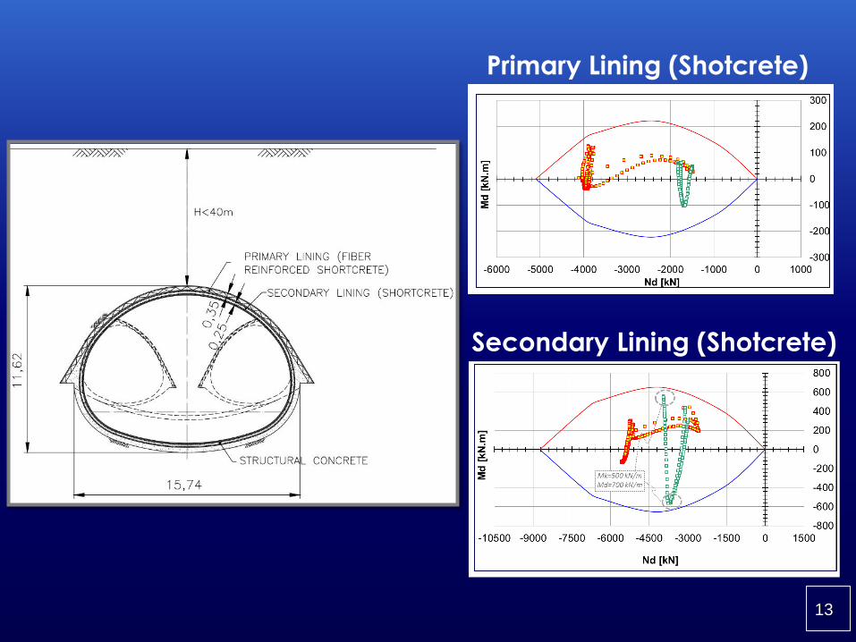
Primary Lining (Shotcrete)
Secondary Lining (Shotcrete)
13

Rotation capacity of plastic hinges
(adapted from NBR 6118:2003),
where x is the depth of the neutral
line and d is the cantilever of
reinforcement.
14

Single-shell lining – Germany (single track tunnels, Pöttler & Klapperich, 2001)
C- claystone; M – marl; S - sandstone
Year 1981-83 1982 1984-87 1987-89
Ground mass S/M S/M M C
Pressure (bar) 0.5 0.5 0.5 0.6
Thickness (cm) 37 25 39 40
Year 1987-89 1989-90 1989-92 1981 1991
Ground mass C M M M C/M
Pressure (bar) 0.6 0 1.2 0.5 0
Thickness (cm) 25 40 55 30 35
15

Single-shell lining - São Paulo Metro
Single track tunnels (~ 6m diameter)
• Year: 1981 - 1992
• Ground mass: stiff clays and water bearing sands
• Pressure: 0.5 to 2.0 bar
• Total thickness (sprayed concrete): 20 to 25 cm
16
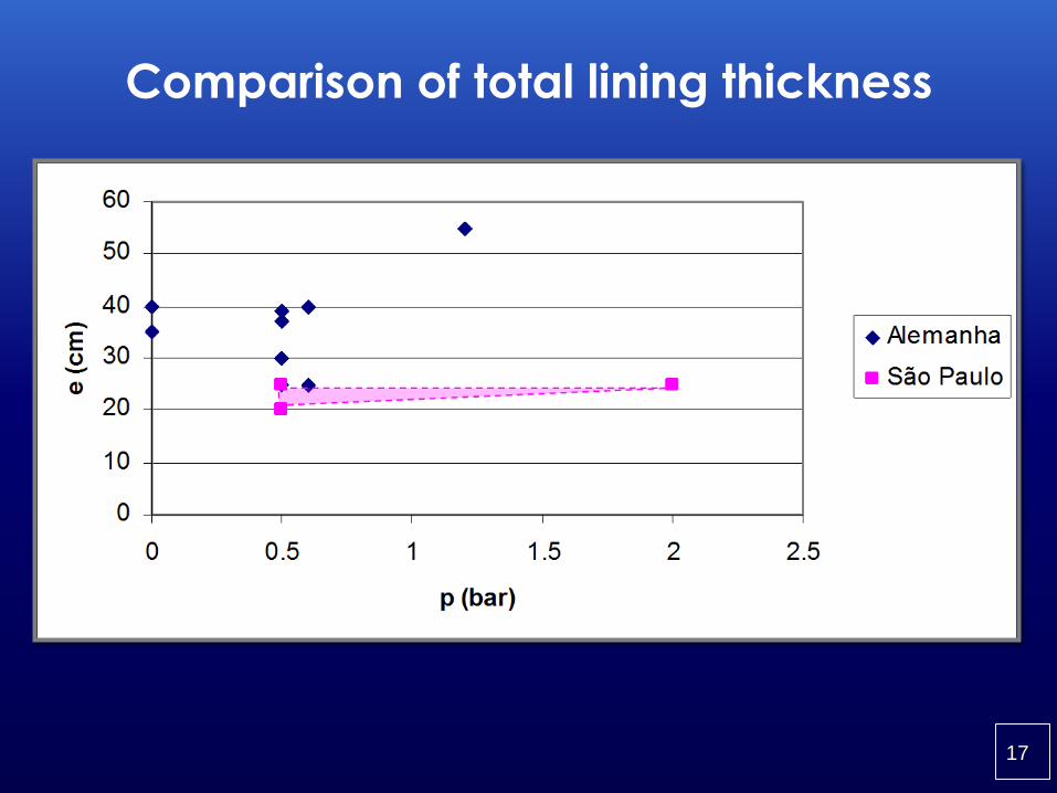
Comparison of total lining thickness
17

São Paulo Metro North Extension (1989)
18

Santiago Metro, Estación Cerro Blanco
19

Rio de Janeiro Metro - Arcoverde Station
20

Stockholm Metro
21

3 – Consequences of potential
cccclogging of geotextiles
22

Water pressure on tunnel lining – potential
clogging of geotextiles
(Shin et al., 2005)
• Time-dependent problem
• Non-woven geotextiles loose drainage capacity (clogging
and compression)
• Role of permanent lining
• Limited (or no) long-term instrumentation
• Coupled numerical analyses
23

Loss of geotextile drainage capacity
24

Pressure as a function of geotextile drainage
capacity
25

Secondary lining failure – Seoul Metro
26

4 – PVC membrane – concrete
interaction
27

Experimental Program
Ribeiro & Bueno, 2005
Uniaxial compression concrete with PVC membrane and PVC +
geotextile
28

Concrete and membrane perpendicular flat
29

Concrete and membrane perpendicular flat
additional displacement
sigma x d5-d3
0
5
10
15
20
25
30
35
-0.1 0 0.1 0.2 0.3 0.4 0.5
d (mm)
s (
MP
a)
30

Perpendicular undulated membrane CP7
31

Perpendicular membrane with voids
CP 17
CP17
0
2
4
6
8
10
12
0 0.2 0.4 0.6 0.8 1 1.2 1.4
d (mm)
s (
MP
a)
32

Relative deformability
1 a 3 4 a 6 7 a 9 16 a 18
E rel (%) 100 32,5 28,1 24.0
CV (%) 0.01 40.12 42.02 46.10
1 a 3 4 a 6 7 a 9 16 a 18
E rel (%) 100 17.3 3.7 4.3
CV (%) 0.01 72.00 33.16 65.41
Membrane
Membrane + geotextile
33

Normal stiffness of interfaces
Specimens Kn (MPa/mm)
4 – 6 M 38,5
7 – 9 M 31,3
16-18 M 25,3
4 – 6 M+G 16,7
7 – 9 M+G 3,1
16-18 M 3,6
34

0
Direct shear
Cisalhamento de interface
0
10
20
30
40
50
60
0,0 1,0 2,0 3,0 4,0 5,0 6,0 7,0 8,0 9,0 10,0 11,0
deslocamento (mm)
Ten
são
(kP
a)
25 kPa
50 kPa
75 kPa
t = 5 + stan34,3 (kPa)35

5 – Spray-on membrane – concrete
interaction: tests and FEM analysis
36

Sprayed concrete linign interaction with
sprayed-on membrane(Nakashima et al., 2015; Cambridge and Ruhr Universities)
• Full scale specimens of sprayed concrete isolated by
waterproofing membrane
• 4-point bending tests to simulate high bending moments
• Excentric compression tests (high hoop stresses)
37

4-point bending test
(large bending moments)
38

Excentric compression test
(high hoop stresses)
39

4-point bending test
40

Excentric compression test
41
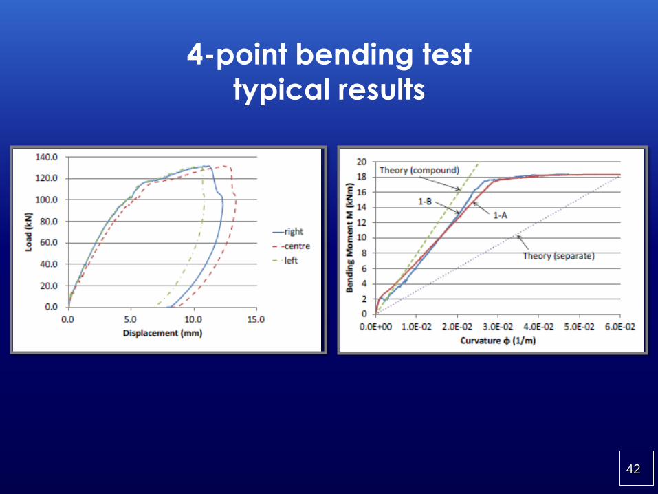
4-point bending test
typical results
42

Analysis of progressive water level rising
Density
ρm=2100 kg/m³ρs=2400 kg/m³
Cohesion
cm=200 kPa
Friction angle
fm=25º
Dilatancy
φm=22,5º
Elasticity
Em= 3,16 GPa,νm=0,3Es= 21 GPa,νs=0,3
Parameter Value Normal stiffness 16,0 MPa/mm Shear stiffness 3,6 MPa/mm
43

Results of strucutural interaction
Stage of secundary lining
Stage WL - 1Stage WL - 2Stage WL - 3Stage WL - 4
Relative displacementsDisplacements – secondary liningStage WL-4: Internal forces in the liningStage 4: PlasticityNormal force – secondary lining Bending moment – secondary lining
44

6 – Creep behavior of PVC
membranes subjected to
compression
45

N.A 1
N.A 2
Buoyancy in shaft lined with concrete and
sheet membrane
U
46

R = U - P
R = Reaction of primary sprayed concrete
P
R
U
Reaction of primary on secondary lining
47

t
se MPa 6
s 6MPa
s 6MPa
Long-term interaction
Primary lining – membrane – secondary lining
48

Punching testASTM D 4833
F 8mm tip
Non-representative condition
49

Creep test under localized load
F F
Flat tip Spherical tip
Constant force
Time-dependent displacement
50

Test set up
51

Typical result
s = 6,7 MPa (shade)
Sphere diameter= 1.22cm
Deformação Lenta
0,00
0,50
1,00
1,50
2,00
2,50
0 500 1000 1500 2000 2500
Tempo (s)
Deslo
cam
en
to (
mm
)
52

7 - Conclusions
53

• Inflow criteria: operation conditions and durability
• Adavantages of umbrella-type systems: lower structural
demand; pre-grouting eventually needed
• Use of sheet membranes does not allow primary –
secondary lining interaction
• Spray-on membranes allow primary – secondary lining
interaction
• Long term compression of sheet membranes on sprayed
concrete surfaces not recommended
• Importance of the role of final lining
54