Embed Size (px)
Citation preview
16-1
16Structural Concrete
Repair
Randall W. Poston, Ph.D., P.E.*
16.1 Introduction ......................................................................16-116.2 Limit States Design for Repair .........................................16-216.3 Evaluation ..........................................................................16-3
Information Gathering • Visual Inspection • Testing
16.4 Structural Implications .....................................................16-816.5 Repair Principles .............................................................16-10
Material Selection • Preparation • Cleaning and Protecting Reinforcement • Curing • Crack Repair • Corrosion Protection • Strengthening
16.6 Repair of Unbonded Post-Tensioned Concrete Structures.........................................................16-16Do Nothing • Tendon Splice or Replacement
16.7 Construction Issues.........................................................16-1916.8 Long-Term Repair Performance.....................................16-2016.9 Case Study........................................................................16-20
Background • Repair Strategy • Life-Cycle Cost Analysis • Impact-Echo to Assess Deterioration • Reliability in Assessing Deterioration • Cathodic Protection • Structural Analysis • Life Safety Implications • Cost Savings • Conclusions • Reports, Standards, and Guidelines
References ...................................................................................16-41
16.1 Introduction
Concrete has been used as a construction material in a wide variety of structures ranging from buildingsand parking structures to bridges, dams, earth-retaining structures, pressure vessels, tanks, boats, andoffshore platforms. Today, it is the most widely used construction material. As with other forms ofinfrastructure, there is an ever-increasing need to evaluate and repair concrete structures. Repairs maybe required for a variety of reasons, ranging from a change in the space requirements of the structure tothe deterioration of concrete and corrosion of the steel reinforcement. Although most concrete structureshave good long-term performance records, deterioration problems have occurred because of poor con-struction practices, poor design, lack of quality materials, and aggressive environmental exposure. Perhapsthe most-cited statistic in the technical concrete literature concerns the extent of deterioration of this
* Principal of WDP & Associates, Inc., Austin, Texas, and chairman, ACI Committee 318; expert in structural designboth in reinforced and prestressed concrete and in retrofit of concrete structures.
© 2008 by Taylor & Francis Group, LLC
16-2 Concrete Construction Engineering Handbook
country’s roads and bridges, often referred to as the nation’s highway infrastructure. The AmericanAssociation of State Highway and Transportation Officials (AASHTO) rates 40% of U.S. highways asbelow minimum standards of engineering. According to the U.S. Department of Transportation, 230,000out of the 575,000 bridges on primary and secondary roads are structurally deficient or functionallyobsolete. It has been estimated that between $18 billion and $21 billion is spent by owners for repair,protection, and strengthening (Strategic Development Council, 1996). The value of the concrete-basedinfrastructure in the United States is estimated to be $8 trillion. And, as was so simply put in a Smithsonianarticle, “a lot of that concrete needs fixing” (Wolkomir, 1994).
Repair of structural concrete—that is, repair of structures in which concrete is the principal load-carrying material—can be classified into three major categories: rehabilitation, where repairs are con-ducted to extend the service life of the structure; restoration, where repairs are effected to upgrade thefunctionality or change the use of the structure; and strengthening, to restore the intended load capacityof the structure or perhaps, as in the case of restoration, increase its capacity because of an anticipatedchange in use. As can be surmised, the boundaries between rehabilitation, restoration, and strengtheningof concrete structures often overlap. The principal objectives of a repair are to ensure safety and structuralintegrity, extend useful life, improve aesthetics, change use, or to improve serviceability. The design ofrepairs must, therefore, address strength, durability, and serviceability analogous to the limit statesconsidered in the design of a new structure.
It is not the intent of this chapter to present a comprehensive treatise of all aspects of the repair ofconcrete structures. Detailed information is available in the literature with regard to concrete preparation,repair materials, and execution of repair construction. Rather, the objective is to present the structuralconcepts concerning concrete repair that include evaluation procedures and general design concepts. Thestructural guidelines presented are generally applicable to all types of concrete structures, includingbridges, buildings, water-containing structures, parking garages, and special structures. A detailed casestudy of an infrastructure repair project is presented to demonstrate the importance of proper evaluationwithin the context of a repair project. This comprehensive case study also illustrates the various structuralanalysis and design techniques that are sometimes necessary to ensure a cost-effective solution in a large-scale infrastructure repair project.
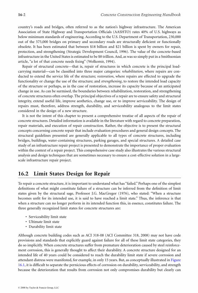
16.2 Limit States Design for Repair
To repair a concrete structure, it is important to understand what has “failed.” Perhaps one of the simplestdefinitions of what might constitute failure of a structure can be inferred from the definition of limitstates given by the structural sage, Professor J.G. MacGregor (1976), who stated: “When a structurebecomes unfit for its intended use, it is said to have reached a limit state.” Thus, the inference is thatwhen a structure can no longer perform in its intended function this, in essence, constitutes failure. Thethree generally recognized limit states for concrete structures are:
• Serviceability limit state• Ultimate limit state• Durability limit state
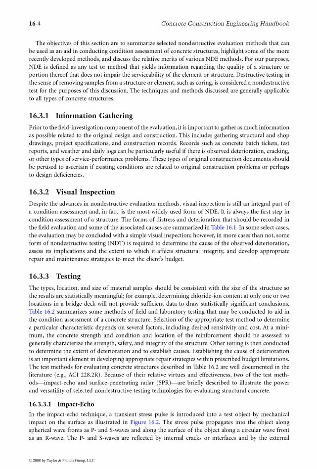
Although concrete building codes such as ACI 318-08 (ACI Committee 318, 2008) may not have codeprovisions and standards that explicitly guard against failure for all of these limit state categories, theydo so implicitly. When concrete structures suffer from premature deterioration caused by steel reinforce-ment corrosion, this is generally thought to affect their durability. A concrete structure designed for anintended life of 40 years could be considered to reach the durability limit state if severe corrosion andattendant distress were manifested, for example, in only 15 years. But, as conceptually illustrated in Figure16.1, it is difficult to separate the pernicious effects of corrosion on durability, serviceability, and strengthbecause the deterioration that results from corrosion not only compromises durability but clearly can
© 2008 by Taylor & Francis Group, LLC

Structural Concrete Repair 16-3
also impair the serviceability and strength of the structure. In fact, there is a confluence of limit stateswith regard to the effects of deterioration in structural concrete. It is therefore necessary to design concreterepairs to satisfy all three limit states.
16.3 Evaluation
Prior to undertaking repairs to concrete structures, a condition assessment to determine the existingconditions and nature and causes of observed distress must be conducted; otherwise, the absence of thisinformation could lead to a high risk of failure of the repair. The extent of the condition assessmentdepends largely on the objectives of the repairs. The factors that affect the repair objectives include safetyand structural integrity, the desired service-life extension, change in intended use or loading requirements,serviceability, aesthetics, and cost. Internationally recognized organizations, such as the American Societyof Civil Engineers (ASCE) and the American Concrete Institute (ACI), have published guidelines forcondition assessment of structures (ASCE, 2000).
The Strategic Highway Research Program (SHRP) was established in 1987 by Congress to improve theperformance and durability of the nation’s highway systems (TRB, 1986). As part of this effort, a numberof nondestructive evaluation (NDE) tools were developed that have been implemented by states and localgovernment agencies, by industry, and by private sectors. Some of the methods developed by SHRPinclude alkali–silica reactivity (ASR) test methods and a rapid method for determining chloride contentand the rate of corrosion of steel reinforcement in hardened concrete. These, along with other existingand emerging NDE techniques, have aided in diagnosing problems, specifying repairs, and quantifyingthe extent of adverse conditions and deterioration.
A condition assessment of a concrete structure may be necessary even if repairs are not contemplated.In some cases, condition assessment is required for determining the load rating of a structure. Moreover,a condition assessment may be conducted in an ongoing inspection program simply to show that astructure is structurally sound. In fact, the Federal Highway Administration (FHWA) has mandatedbiennial inspections for bridges since 1968. Traditionally, a condition assessment of a concrete structuregenerally meant a visual examination of the structure along with select coring of various concrete elementsfor compressive strength testing, perhaps a petrographic analysis, and sounding by chain drag. Althoughthese techniques are still helpful and largely necessary, over the past two decades other very valuable andpractical nondestructive evaluation methods have been developed. These newer generation nondestruc-tive methods greatly improve and increase the efficiency of the condition assessment process for concretestructures. Some of these recently developed nondestructive evaluation technologies allow for relativelyrapid inspection of damage and deterioration of concrete structures.
FIGURE 16.1 Limit states in structural concrete repair.
Strength Serviceability
Failure
Durability
© 2008 by Taylor & Francis Group, LLC
16-4 Concrete Construction Engineering Handbook
The objectives of this section are to summarize selected nondestructive evaluation methods that canbe used as an aid in conducting condition assessment of concrete structures, highlight some of the morerecently developed methods, and discuss the relative merits of various NDE methods. For our purposes,NDE is defined as any test or method that yields information regarding the quality of a structure orportion thereof that does not impair the serviceability of the element or structure. Destructive testing inthe sense of removing samples from a structure or element, such as coring, is considered a nondestructivetest for the purposes of this discussion. The techniques and methods discussed are generally applicableto all types of concrete structures.
16.3.1 Information Gathering
Prior to the field-investigation component of the evaluation, it is important to gather as much informationas possible related to the original design and construction. This includes gathering structural and shopdrawings, project specifications, and construction records. Records such as concrete batch tickets, testreports, and weather and daily logs can be particularly useful if there is observed deterioration, cracking,or other types of service-performance problems. These types of original construction documents shouldbe perused to ascertain if existing conditions are related to original construction problems or perhapsto design deficiencies.
16.3.2 Visual Inspection
Despite the advances in nondestructive evaluation methods, visual inspection is still an integral part ofa condition assessment and, in fact, is the most widely used form of NDE. It is always the first step incondition assessment of a structure. The forms of distress and deterioration that should be recorded inthe field evaluation and some of the associated causes are summarized in Table 16.1. In some select cases,the evaluation may be concluded with a simple visual inspection; however, in more cases than not, someform of nondestructive testing (NDT) is required to determine the cause of the observed deterioration,assess its implications and the extent to which it affects structural integrity, and develop appropriaterepair and maintenance strategies to meet the client’s budget.
16.3.3 Testing
The types, location, and size of material samples should be consistent with the size of the structure sothe results are statistically meaningful; for example, determining chloride-ion content at only one or twolocations in a bridge deck will not provide sufficient data to draw statistically significant conclusions.Table 16.2 summarizes some methods of field and laboratory testing that may be conducted to aid inthe condition assessment of a concrete structure. Selection of the appropriate test method to determinea particular characteristic depends on several factors, including desired sensitivity and cost. At a mini-mum, the concrete strength and condition and location of the reinforcement should be assessed togenerally characterize the strength, safety, and integrity of the structure. Other testing is then conductedto determine the extent of deterioration and to establish causes. Establishing the cause of deteriorationis an important element in developing appropriate repair strategies within prescribed budget limitations.The test methods for evaluating concrete structures described in Table 16.2 are well documented in theliterature (e.g., ACI 228.2R). Because of their relative virtues and effectiveness, two of the test meth-ods—impact-echo and surface-penetrating radar (SPR)—are briefly described to illustrate the powerand versatility of selected nondestructive testing technologies for evaluating structural concrete.
16.3.3.1 Impact-Echo
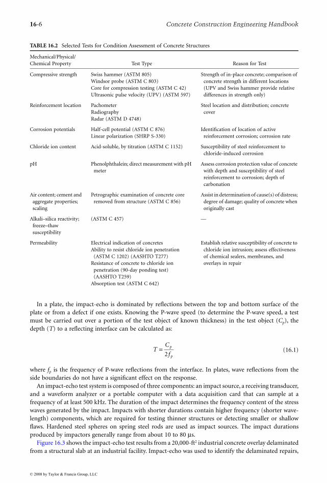
In the impact-echo technique, a transient stress pulse is introduced into a test object by mechanicalimpact on the surface as illustrated in Figure 16.2. The stress pulse propagates into the object alongspherical wave fronts as P- and S-waves and along the surface of the object along a circular wave frontas an R-wave. The P- and S-waves are reflected by internal cracks or interfaces and by the external
© 2008 by Taylor & Francis Group, LLC

Structural Concrete Repair 16-5
boundaries of the object. The arrival of these reflected waves at the surface where the impact was generatedproduces displacements that are monitored by a transducer. If the transducer is placed close to the impactpoint, the waveform is dominated by displacements caused by P-wave arrivals.
Because it is difficult and time consuming to analyze time-domain waveforms to determine the arrivaltimes of reflected waves and thereby calculate the depth of reflecting interfaces, waveforms are trans-formed into the frequency domain using the fast Fourier transform (FFT) technique (Sansalone andCarino, 1986, 1988). The resulting amplitude spectrum is used to identify the dominant frequenciespresent in the waveform. Because these frequencies are produced by multiple wave reflections betweeninterfaces, they can be used to determine if a structure is solid or if flaws exist within the structure. Eachtype of structure—plate (bridge deck, slab), bar (beam, column), hollow cylinder (pipe, shaft line),etc.—exhibits a characteristic frequency response when subjected to impact. The presence of a flaw affectsthis response.
TABLE 16.1 Forms of Concrete Distress and Deterioration Noted in a Visual Condition Assessment
Description Typical Causes
Cracking Plastic shrinkageDrying shrinkageRestraintSubgrade support deficienciesAbsence or location of vapor barrierExpansionCorrosion of reinforcing steel/prestressing steel or other embedded metalComponentsThermal loadingVehicular impactOverloadingAggregate reaction
Scaling Inadequate air content Finishing problems Freeze-thaw cycling Chemical deicers
Spalling Aggregate reaction Corrosion Freeze-thaw cycling Construction Poor preparation of construction joints Early-age loading
Disintegration Frozen concrete Freeze-thaw cycling Low strength Chemical attack Sulfate attack
Honeycombing and surface voids Poor placement Poor consolidation Congested reinforcement
Discoloration and staining Different cement production Different water-cement ratios Corrosion Aggregates Use of calcium chloride Curing Finishing Nonuniform absorption of forms
Efflorescence Calcium carbonate and other mineral deposits caused by leakage
© 2008 by Taylor & Francis Group, LLC
16-6 Concrete Construction Engineering Handbook
In a plate, the impact-echo is dominated by reflections between the top and bottom surface of theplate or from a defect if one exists. Knowing the P-wave speed (to determine the P-wave speed, a testmust be carried out over a portion of the test object of known thickness) in the test object (Cp), thedepth (T) to a reflecting interface can be calculated as:
(16.1)
where fp is the frequency of P-wave reflections from the interface. In plates, wave reflections from theside boundaries do not have a significant effect on the response.
An impact-echo test system is composed of three components: an impact source, a receiving transducer,and a waveform analyzer or a portable computer with a data acquisition card that can sample at afrequency of at least 500 kHz. The duration of the impact determines the frequency content of the stresswaves generated by the impact. Impacts with shorter durations contain higher frequency (shorter wave-length) components, which are required for testing thinner structures or detecting smaller or shallowflaws. Hardened steel spheres on spring steel rods are used as impact sources. The impact durationsproduced by impactors generally range from about 10 to 80 µs.
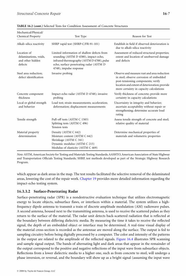
Figure 16.3 shows the impact-echo test results from a 20,000-ft2 industrial concrete overlay delaminatedfrom a structural slab at an industrial facility. Impact-echo was used to identify the delaminated repairs,
TABLE 16.2 Selected Tests for Condition Assessment of Concrete Structures
Mechanical/Physical/Chemical Property Test Type Reason for Test
Compressive strength Swiss hammer (ASTM 805) Windsor probe (ASTM C 803) Core for compression testing (ASTM C 42)Ultrasonic pulse velocity (UPV) (ASTM 597)
Strength of in-place concrete; comparison of concrete strength in different locations (UPV and Swiss hammer provide relative differences in strength only)
Reinforcement location PachometerRadiographyRadar (ASTM D 4748)
Steel location and distribution; concrete cover
Corrosion potentials Half-cell potential (ASTM C 876)Linear polarization (SHRP S-330)
Identification of location of active reinforcement corrosion; corrosion rate
Chloride ion content Acid-soluble, by titration (ASTM C 1152) Susceptibility of steel reinforcement to chloride-induced corrosion
pH Phenolphthalein; direct measurement with pH meter
Assess corrosion protection value of concrete with depth and susceptibility of steel reinforcement to corrosion; depth of carbonation
Air content; cement and aggregate properties; scaling
Petrographic examination of concrete core removed from structure (ASTM C 856)
Assist in determination of cause(s) of distress; degree of damage; quality of concrete when originally cast
Alkali–silica reactivity; freeze–thaw susceptibility
(ASTM C 457) —
Permeability Electrical indication of concretesAbility to resist chloride ion penetration
(ASTM C 1202) (AASHTO T277)Resistance of concrete to chloride ion
penetration (90-day ponding test) (AASHTO T259)
Absorption test (ASTM C 642)
Establish relative susceptibility of concrete to chloride ion intrusion; assess effectiveness of chemical sealers, membranes, and overlays in repair
TC
fp
p
=2
© 2008 by Taylor & Francis Group, LLC
Structural Concrete Repair 16-7
which appear as dark areas in the map. The test results facilitated the selective removal of the delaminatedareas, lowering the cost of the repair work. Chapter 19 provides more detailed information regarding theimpact-echo testing system.
16.3.3.2 Surface-Penetrating Radar
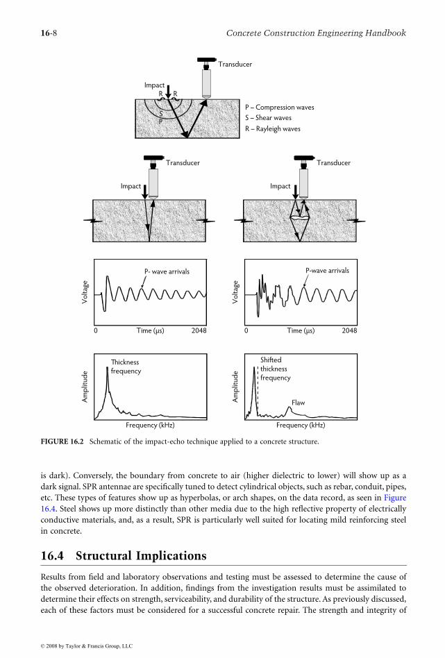
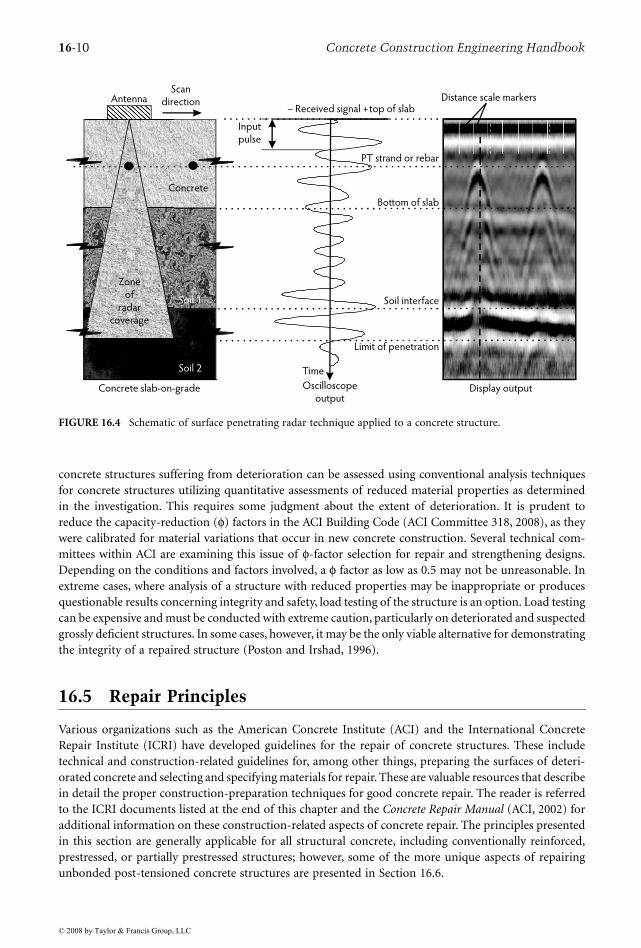
Surface-penetrating radar (SPR) is a nondestructive evaluation technique that utilizes electromagneticenergy to locate objects, subsurface flaws, or interfaces within a material. The system utilizes a high-frequency dipole antenna to transmit a train of discrete amplitude modulation (AM) radiowave pulses.A second antenna, housed next to the transmitting antenna, is used to receive the scattered pulses as theyreturn to the surface of the material. The radar unit detects back-scattered radiation that is reflected atthe boundary between differing dielectric media. By measuring the time it takes to receive the reflectedsignal, the depth of an embedded object or interface may be determined. A real-time visual display ofthe material cross-section is recorded as the antennae are moved along the surface. The output is fed tosampling circuitry before being digitally processed by a computer. The color and intensity of the patternsin the output are related to the amplitude of the reflected signals. Figure 16.4 illustrates SPR scanningand sample signal output. The bands of alternating light and dark areas that appear in the remainder ofthe output correspond to the positive and negative reflections of the input wave from subsurface objects.Reflections from a lower dielectric media to a higher one, such as from concrete to steel, will undergo aphase inversion, or reversal, and the boundary will show up as a bright signal (assuming the input wave
TABLE 16.2 (cont.) Selected Tests for Condition Assessment of Concrete Structures
Mechanical/Physical/Chemical Property Test Type Reason for Test
Alkali–silica reactivity SHRP rapid test (SHRP-C/FR-91-101) Establish in field if observed deterioration is due to alkali–silica reactivity
Location of delaminations, voids, and other hidden defects
Limited information of shallow defects from sounding (ASTM D 4580), impact-echo, infrared thermography (ASTM D 4788), pulse echo, surface-penetrating radar (ASTM D 4748), impulse response
Assessment of reduced structural properties; extent and location of unobserved damage and defects
Steel area reduction; defect identification
Invasive probing Observe and measure rust and area reduction in steel; observe corrosion of embedded post-tensioning components; verify location and extent of deterioration; provide more certainty in capacity calculations
Concrete component thickness
Impact-echo radar (ASTM D 4748); invasive probing
Verify thickness of concrete; provide more certainty in capacity calculations
Local or global strength and behavior
Load test; strain measurements; acceleration; deformation; displacement measurements
Uncertainty in integrity and behavior; ascertain acceptability without repair or strengthening; determine accurate load rating
Tensile strength Pull-off tests (ASTM C 1583)Splitting tests (ASTM C 496)Tension tests
Assess tensile strength of concrete and steel; relative quality of material
Material property determination
Density (ASTM C 642)Moisture content (ASTM C 642)Shrinkage (ASTM C 341)Dynamic modulus (ASTM C 215)Modulus of elasticity (ASTM C 469)
Determine mechanical properties of materials and volumetric properties
Note: ASTM, American Society for Testing and Materials Testing Standards; AASHTO, American Association of State Highwayand Transportation Officials Testing Standards; SHRP, test methods developed as part of the Strategic Highway ResearchProgram.
© 2008 by Taylor & Francis Group, LLC
16-8 Concrete Construction Engineering Handbook
is dark). Conversely, the boundary from concrete to air (higher dielectric to lower) will show up as adark signal. SPR antennae are specifically tuned to detect cylindrical objects, such as rebar, conduit, pipes,etc. These types of features show up as hyperbolas, or arch shapes, on the data record, as seen in Figure16.4. Steel shows up more distinctly than other media due to the high reflective property of electricallyconductive materials, and, as a result, SPR is particularly well suited for locating mild reinforcing steelin concrete.
16.4 Structural Implications
Results from field and laboratory observations and testing must be assessed to determine the cause ofthe observed deterioration. In addition, findings from the investigation results must be assimilated todetermine their effects on strength, serviceability, and durability of the structure. As previously discussed,each of these factors must be considered for a successful concrete repair. The strength and integrity of
FIGURE 16.2 Schematic of the impact-echo technique applied to a concrete structure.
Thickness
frequency
Frequency (kHz)
Am
plit
ud
e
Shifted
thickness
frequency
Flaw
Frequency (kHz)
Am
plit
ud
e
Vo
ltag
e
Time (µs)0 2048
P- wave arrivals
Time (µs)
Vo
ltag
e
0 2048
P-wave arrivals
Impact
Transducer
Impact
Transducer
P – Compression waves
S – Shear waves
R – Rayleigh waves
ImpactR
SP
R
Transducer
© 2008 by Taylor & Francis Group, LLC

Structu
ral Con
crete Repair
16-9
FIGURE 16.3 Results from impact-echo testing on an industrial lab showing areas of delamination.
16
5
3 7
8
4
2
A
B
C
D
E
F
G
H
I
J
K
L
M
N
O
P
Q
R
S
T
102030405060708090 1
12
Legend
Delaminated area
SCH
UPA
C
U
V
W
XY
© 2008 by Taylor & Francis Group, LLC
16-10 Concrete Construction Engineering Handbook
concrete structures suffering from deterioration can be assessed using conventional analysis techniquesfor concrete structures utilizing quantitative assessments of reduced material properties as determinedin the investigation. This requires some judgment about the extent of deterioration. It is prudent toreduce the capacity-reduction (φ) factors in the ACI Building Code (ACI Committee 318, 2008), as theywere calibrated for material variations that occur in new concrete construction. Several technical com-mittees within ACI are examining this issue of φ-factor selection for repair and strengthening designs.Depending on the conditions and factors involved, a φ factor as low as 0.5 may not be unreasonable. Inextreme cases, where analysis of a structure with reduced properties may be inappropriate or producesquestionable results concerning integrity and safety, load testing of the structure is an option. Load testingcan be expensive and must be conducted with extreme caution, particularly on deteriorated and suspectedgrossly deficient structures. In some cases, however, it may be the only viable alternative for demonstratingthe integrity of a repaired structure (Poston and Irshad, 1996).
16.5 Repair Principles
Various organizations such as the American Concrete Institute (ACI) and the International ConcreteRepair Institute (ICRI) have developed guidelines for the repair of concrete structures. These includetechnical and construction-related guidelines for, among other things, preparing the surfaces of deteri-orated concrete and selecting and specifying materials for repair. These are valuable resources that describein detail the proper construction-preparation techniques for good concrete repair. The reader is referredto the ICRI documents listed at the end of this chapter and the Concrete Repair Manual (ACI, 2002) foradditional information on these construction-related aspects of concrete repair. The principles presentedin this section are generally applicable for all structural concrete, including conventionally reinforced,prestressed, or partially prestressed structures; however, some of the more unique aspects of repairingunbonded post-tensioned concrete structures are presented in Section 16.6.
FIGURE 16.4 Schematic of surface penetrating radar technique applied to a concrete structure.
Distance scale markers
Soil interface
Limit of penetration
Bottom of slab
Oscilloscope
outputDisplay output
AntennaScan
direction
Concrete slab-on-grade
Soil 2
Zone
of
radar
coverage
Input
pulse
– Received signal + top of slab
Concrete
PT strand or rebar
Time
Soil 1
© 2008 by Taylor & Francis Group, LLC
Structural Concrete Repair 16-11
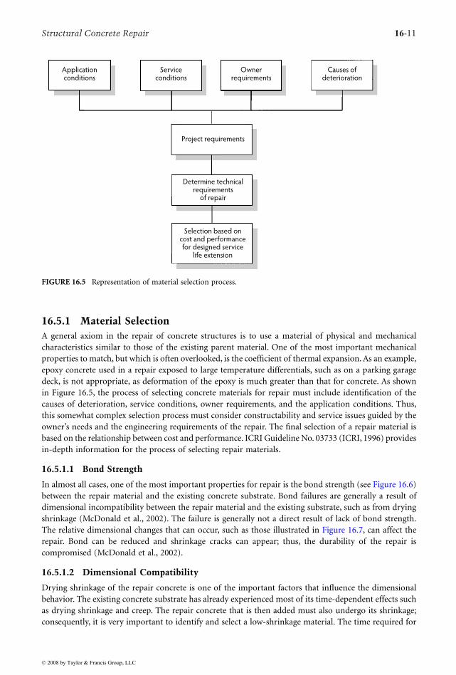
16.5.1 Material SelectionA general axiom in the repair of concrete structures is to use a material of physical and mechanicalcharacteristics similar to those of the existing parent material. One of the most important mechanicalproperties to match, but which is often overlooked, is the coefficient of thermal expansion. As an example,epoxy concrete used in a repair exposed to large temperature differentials, such as on a parking garagedeck, is not appropriate, as deformation of the epoxy is much greater than that for concrete. As shownin Figure 16.5, the process of selecting concrete materials for repair must include identification of thecauses of deterioration, service conditions, owner requirements, and the application conditions. Thus,this somewhat complex selection process must consider constructability and service issues guided by theowner’s needs and the engineering requirements of the repair. The final selection of a repair material isbased on the relationship between cost and performance. ICRI Guideline No. 03733 (ICRI, 1996) providesin-depth information for the process of selecting repair materials.
16.5.1.1 Bond Strength
In almost all cases, one of the most important properties for repair is the bond strength (see Figure 16.6)between the repair material and the existing concrete substrate. Bond failures are generally a result ofdimensional incompatibility between the repair material and the existing substrate, such as from dryingshrinkage (McDonald et al., 2002). The failure is generally not a direct result of lack of bond strength.The relative dimensional changes that can occur, such as those illustrated in Figure 16.7, can affect therepair. Bond can be reduced and shrinkage cracks can appear; thus, the durability of the repair iscompromised (McDonald et al., 2002).
16.5.1.2 Dimensional Compatibility
Drying shrinkage of the repair concrete is one of the important factors that influence the dimensionalbehavior. The existing concrete substrate has already experienced most of its time-dependent effects suchas drying shrinkage and creep. The repair concrete that is then added must also undergo its shrinkage;consequently, it is very important to identify and select a low-shrinkage material. The time required for
FIGURE 16.5 Representation of material selection process.
Ownerrequirements
Selection based oncost and performancefor designed service
life extension
Applicationconditions
Serviceconditions
Causes ofdeterioration
Project requirements
Determine technicalrequirements
of repair
© 2008 by Taylor & Francis Group, LLC

16-12 Concrete Construction Engineering Handbook
a material to achieve dimensional stability is dependent primarily on the ambient temperature andhumidity. It is important to adequately cure the repair to mitigate shrinkage cracking. It is recommendedthat the repair concrete material be limited to less than 0.05% shrinkage at 28 days as measured by ASTMC 157 (McDonald et al., 2002). Other properties of the repair material that are important in achievingdimensional compatibility include the coefficient of thermal expansion, modulus of elasticity, and creep,both compressive and tensile. In general, these properties in the repair material should reasonably matchthose of the existing concrete to achieve dimensional compatibility. By matching these properties, crackingin the repair will be mitigated. This will help ensure long-term durability of the repair.
16.5.1.3 Durability Considerations
The durability of the concrete repair is its ability to resist structural loading and environmental conditionswithout degradation and deterioration. The environmental conditions that may affect durability includeweathering, temperature changes, chemical attack, and abrasion, among others. It is essential that thecause and extent of deterioration of an existing concrete structure be identified. Based on this information,a strategy can be identified to satisfy the durability limit state of the repair.
Material properties that can affect the durability of a repair include permeability, water-vapor trans-mission, freeze–thaw resistance, scaling resistance, sulfate resistance, abrasion resistance, and alkali–silicareaction. Permeability is the rate of transmission of a liquid through the concrete. In general, the lower
FIGURE 16.6 Bond strength, an important property for the success of break repair.
FIGURE 16.7 Dimensional changes in repair material that have resulted in restrained shrinkage cracks.
Interfacial bond plane
Repair material
Existing
concrete
substrate
Restrained shrinkage cracks in repair material
Substrate
Restraint boundary
© 2008 by Taylor & Francis Group, LLC
Structural Concrete Repair 16-13
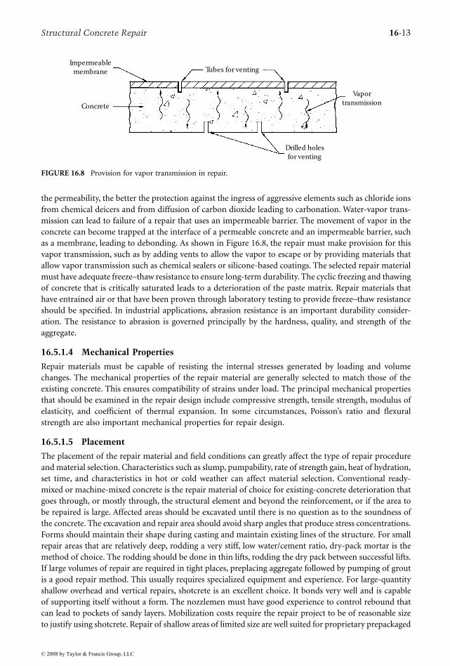
the permeability, the better the protection against the ingress of aggressive elements such as chloride ionsfrom chemical deicers and from diffusion of carbon dioxide leading to carbonation. Water-vapor trans-mission can lead to failure of a repair that uses an impermeable barrier. The movement of vapor in theconcrete can become trapped at the interface of a permeable concrete and an impermeable barrier, suchas a membrane, leading to debonding. As shown in Figure 16.8, the repair must make provision for thisvapor transmission, such as by adding vents to allow the vapor to escape or by providing materials thatallow vapor transmission such as chemical sealers or silicone-based coatings. The selected repair materialmust have adequate freeze–thaw resistance to ensure long-term durability. The cyclic freezing and thawingof concrete that is critically saturated leads to a deterioration of the paste matrix. Repair materials thathave entrained air or that have been proven through laboratory testing to provide freeze–thaw resistanceshould be specified. In industrial applications, abrasion resistance is an important durability consider-ation. The resistance to abrasion is governed principally by the hardness, quality, and strength of theaggregate.
16.5.1.4 Mechanical Properties
Repair materials must be capable of resisting the internal stresses generated by loading and volumechanges. The mechanical properties of the repair material are generally selected to match those of theexisting concrete. This ensures compatibility of strains under load. The principal mechanical propertiesthat should be examined in the repair design include compressive strength, tensile strength, modulus ofelasticity, and coefficient of thermal expansion. In some circumstances, Poisson’s ratio and flexuralstrength are also important mechanical properties for repair design.
16.5.1.5 Placement
The placement of the repair material and field conditions can greatly affect the type of repair procedureand material selection. Characteristics such as slump, pumpability, rate of strength gain, heat of hydration,set time, and characteristics in hot or cold weather can affect material selection. Conventional ready-mixed or machine-mixed concrete is the repair material of choice for existing-concrete deterioration thatgoes through, or mostly through, the structural element and beyond the reinforcement, or if the area tobe repaired is large. Affected areas should be excavated until there is no question as to the soundness ofthe concrete. The excavation and repair area should avoid sharp angles that produce stress concentrations.Forms should maintain their shape during casting and maintain existing lines of the structure. For smallrepair areas that are relatively deep, rodding a very stiff, low water/cement ratio, dry-pack mortar is themethod of choice. The rodding should be done in thin lifts, rodding the dry pack between successful lifts.If large volumes of repair are required in tight places, preplacing aggregate followed by pumping of groutis a good repair method. This usually requires specialized equipment and experience. For large-quantityshallow overhead and vertical repairs, shotcrete is an excellent choice. It bonds very well and is capableof supporting itself without a form. The nozzlemen must have good experience to control rebound thatcan lead to pockets of sandy layers. Mobilization costs require the repair project to be of reasonable sizeto justify using shotcrete. Repair of shallow areas of limited size are well suited for proprietary prepackaged
FIGURE 16.8 Provision for vapor transmission in repair.
Impermeablemembrane
Concrete
Tubes for venting
Drilled holesfor venting
Vaportransmission
© 2008 by Taylor & Francis Group, LLC
16-14 Concrete Construction Engineering Handbook
repair materials. These prepackaged materials often contain polymers to enhance the bond of the materialto the existing concrete substrate; however, it has been observed that some prepackaged repair materialshave excessive shrinkage characteristics and thus are dimensionally incompatible with concrete.
16.5.2 Preparation
In general, deteriorated concrete should be removed to sound concrete substrate. Partial-depth repairsare desirable because less demolition is required, no formwork is required for horizontal repairs, and theyare generally less costly; however, if repair is required on two sides of a slab or wall, then full-depth removalis preferable. Saw cuts around the perimeter of the repair are advisable, particularly in the case of slabsto eliminate feather edges. After deteriorated concrete is removed, the surfaces to be bonded should bethoroughly cleaned, such as by wet sandblasting, then all loose particles should be vacuumed or pressureblown from the repair area. The surface should be thoroughly wet. The repair material should be placedwhen the surface has no standing water. A bonding agent such as a cement slurry coat or epoxy is normallynot necessary but should be utilized if the manufacturer of a prepackaged material recommends their use.
16.5.3 Cleaning and Protecting Reinforcement
Prior to placing the repair material, steel reinforcement and other metal components should be cleanedof corrosion and other scale. Mechanical abrasion can be used, although sandblasting is preferable ifenvironmental conditions permit. There are various components on the market for coating the rein-forcement. These include epoxy, zinc-rich compounds, and cement-based coatings. Epoxy and some ofthe zinc-rich compounds can act as bond breakers and therefore, must be applied carefully. Recentfindings regarding epoxy have raised questions about the appropriateness of its use. It has been speculatedthat the application of epoxy on reinforcing steel in an area under repair results in accelerated corrosionin surrounding areas, sometimes referred to as the anodic ring effect.
16.5.4 Curing
All concrete repairs must be properly cured to ensure hydration of the cement and strength gain and tominimize shrinkage and cracking. Curing should follow the same good practices as for new construction.
16.5.5 Crack Repair
Whether a crack in concrete should be repaired to restore structural integrity or merely sealed is dependenton the nature of the structure and the cause of the crack and on its location and extent. If the stressesthat caused the crack have been relieved by its occurrence, the structural integrity can be restored withsome expectation of permanency. In the case of working or moving cracks, such as cracks that open andclose because of temperature changes, the only satisfactory solution is to seal them with a flexible orextensible material. ACI 224.1R (ACI Committee 224, 1998) provides comprehensive information oncrack repair. Cleaning of the crack is essential before any treatment takes place. All loose particles andforeign material must be removed. The method of cleaning is dependent on the size of the crack and thenature of the contaminants. It may include compressed air, sandblasting, or routing. Restoration of crackswithout restoration of structural integrity requires the use of materials and techniques similar to thoseused in sealing joints. Typically, the cracks are routed and a urethane sealant is applied. A bond breakershould be used on the bottom of the routed crack so bonding occurs on only two sides.
16.5.6 Corrosion Protection
Various corrosion protection strategies are being used in repair and new construction projects. Theirselection depends on the type of structural system, exposure conditions, service life, and, naturally, costs.Selected corrosion protection strategies are summarized in Table 16.3.
© 2008 by Taylor & Francis Group, LLC
Structural Concrete Repair 16-15
16.5.7 Strengthening
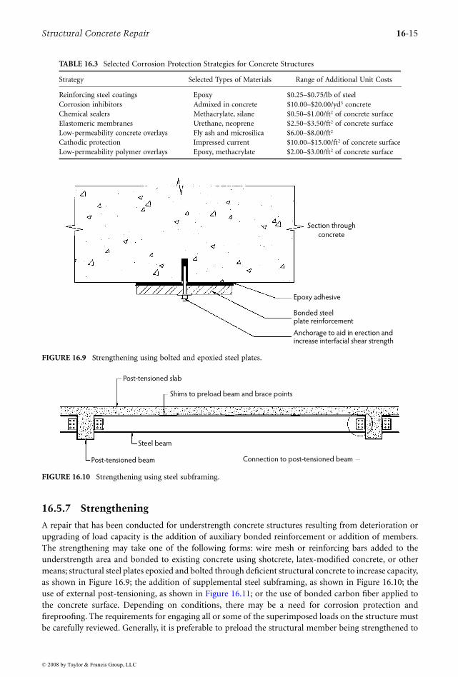
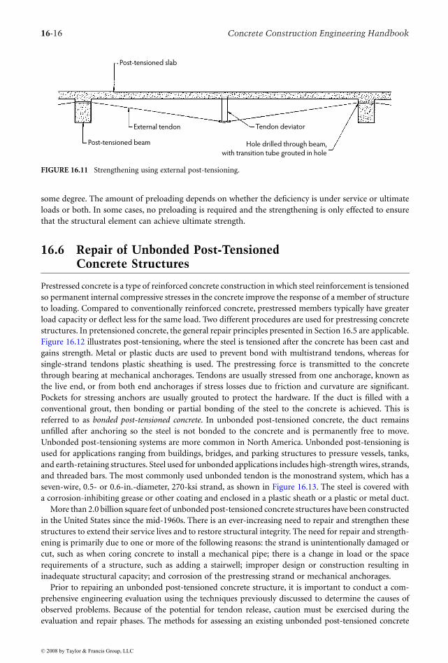
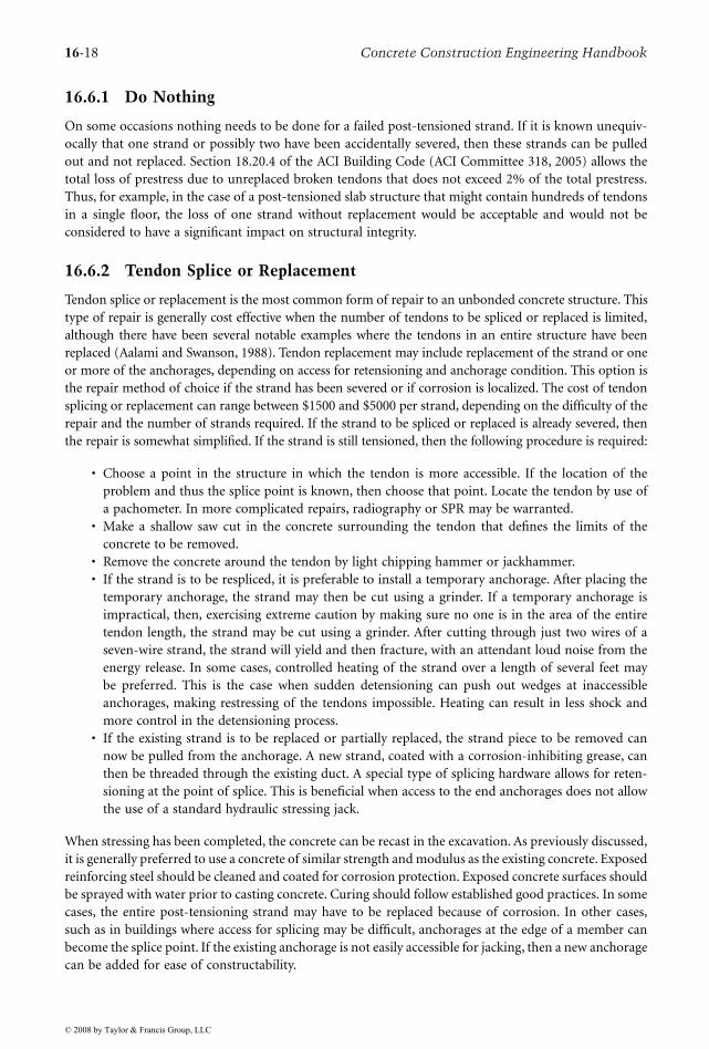
A repair that has been conducted for understrength concrete structures resulting from deterioration orupgrading of load capacity is the addition of auxiliary bonded reinforcement or addition of members.The strengthening may take one of the following forms: wire mesh or reinforcing bars added to theunderstrength area and bonded to existing concrete using shotcrete, latex-modified concrete, or othermeans; structural steel plates epoxied and bolted through deficient structural concrete to increase capacity,as shown in Figure 16.9; the addition of supplemental steel subframing, as shown in Figure 16.10; theuse of external post-tensioning, as shown in Figure 16.11; or the use of bonded carbon fiber applied tothe concrete surface. Depending on conditions, there may be a need for corrosion protection andfireproofing. The requirements for engaging all or some of the superimposed loads on the structure mustbe carefully reviewed. Generally, it is preferable to preload the structural member being strengthened to
TABLE 16.3 Selected Corrosion Protection Strategies for Concrete Structures
Strategy Selected Types of Materials Range of Additional Unit Costs
Reinforcing steel coatings Epoxy $0.25–$0.75/lb of steelCorrosion inhibitors Admixed in concrete $10.00–$20.00/yd3 concreteChemical sealers Methacrylate, silane $0.50–$1.00/ft2 of concrete surfaceElastomeric membranes Urethane, neoprene $2.50–$3.50/ft2 of concrete surfaceLow-permeability concrete overlays Fly ash and microsilica $6.00–$8.00/ft2
Cathodic protection Impressed current $10.00–$15.00/ft2 of concrete surfaceLow-permeability polymer overlays Epoxy, methacrylate $2.00–$3.00/ft2 of concrete surface
FIGURE 16.9 Strengthening using bolted and epoxied steel plates.
FIGURE 16.10 Strengthening using steel subframing.
Section through
concrete
Epoxy adhesive
Bonded steelplate reinforcement
Anchorage to aid in erection andincrease interfacial shear strength
Post-tensioned slab
Shims to preload beam and brace points
Steel beam
Post-tensioned beam Connection to post-tensioned beam
© 2008 by Taylor & Francis Group, LLC
16-16 Concrete Construction Engineering Handbook
some degree. The amount of preloading depends on whether the deficiency is under service or ultimateloads or both. In some cases, no preloading is required and the strengthening is only effected to ensurethat the structural element can achieve ultimate strength.
16.6 Repair of Unbonded Post-Tensioned Concrete Structures
Prestressed concrete is a type of reinforced concrete construction in which steel reinforcement is tensionedso permanent internal compressive stresses in the concrete improve the response of a member of structureto loading. Compared to conventionally reinforced concrete, prestressed members typically have greaterload capacity or deflect less for the same load. Two different procedures are used for prestressing concretestructures. In pretensioned concrete, the general repair principles presented in Section 16.5 are applicable.Figure 16.12 illustrates post-tensioning, where the steel is tensioned after the concrete has been cast andgains strength. Metal or plastic ducts are used to prevent bond with multistrand tendons, whereas forsingle-strand tendons plastic sheathing is used. The prestressing force is transmitted to the concretethrough bearing at mechanical anchorages. Tendons are usually stressed from one anchorage, known asthe live end, or from both end anchorages if stress losses due to friction and curvature are significant.Pockets for stressing anchors are usually grouted to protect the hardware. If the duct is filled with aconventional grout, then bonding or partial bonding of the steel to the concrete is achieved. This isreferred to as bonded post-tensioned concrete. In unbonded post-tensioned concrete, the duct remainsunfilled after anchoring so the steel is not bonded to the concrete and is permanently free to move.Unbonded post-tensioning systems are more common in North America. Unbonded post-tensioning isused for applications ranging from buildings, bridges, and parking structures to pressure vessels, tanks,and earth-retaining structures. Steel used for unbonded applications includes high-strength wires, strands,and threaded bars. The most commonly used unbonded tendon is the monostrand system, which has aseven-wire, 0.5- or 0.6-in.-diameter, 270-ksi strand, as shown in Figure 16.13. The steel is covered witha corrosion-inhibiting grease or other coating and enclosed in a plastic sheath or a plastic or metal duct.
More than 2.0 billion square feet of unbonded post-tensioned concrete structures have been constructedin the United States since the mid-1960s. There is an ever-increasing need to repair and strengthen thesestructures to extend their service lives and to restore structural integrity. The need for repair and strength-ening is primarily due to one or more of the following reasons: the strand is unintentionally damaged orcut, such as when coring concrete to install a mechanical pipe; there is a change in load or the spacerequirements of a structure, such as adding a stairwell; improper design or construction resulting ininadequate structural capacity; and corrosion of the prestressing strand or mechanical anchorages.
Prior to repairing an unbonded post-tensioned concrete structure, it is important to conduct a com-prehensive engineering evaluation using the techniques previously discussed to determine the causes ofobserved problems. Because of the potential for tendon release, caution must be exercised during theevaluation and repair phases. The methods for assessing an existing unbonded post-tensioned concrete
FIGURE 16.11 Strengthening using external post-tensioning.
Post-tensioned slab
Post-tensioned beam
External tendon Tendon deviator
Hole drilled through beam,
with transition tube grouted in hole
© 2008 by Taylor & Francis Group, LLC

Structural Concrete Repair 16-17
structure are, for the most part, the same as for a concrete structure constructed with mild steel reinforce-ment; however, the repair of existing unbonded post-tensioned structures is different in many respects.
The repair of unbonded post-tensioned concrete structures cannot be easily divided into categorieswhere a certain type of repair is best for a certain type of problem. The type of repair depends on theexpected cost of the repair, cause of the problem, the need to maintain service of the structure, whetherthe repair is to a beam, slab or other structural member, and many other factors. Moreover, once repairsbegin, the owner, engineer, and repair contractor must be able to adapt to unobserved latent defects andchanged conditions. The most important axiom in the repair of unbonded post-tensioned structures isto expect the unexpected. The general types of repair of unbonded post-tensioning are classified as (1)do nothing, (2) tendon splice or replacement, and (3) strengthening by adding bonded reinforcement,structural members, or external post-tensioning to improve or increase structural capacity. If the repairis due to a corrosion problem, it is likely that other concrete repairs will be necessary because of thedeterioration that is generally attendant with corrosion. As with all types of concrete repair, extremecaution should be exercised by all individuals during the investigation, demolition, and repair. The needfor shoring and the sequence of repair should be thoroughly thought out prior to starting any work.
FIGURE 16.12 Post-tensioned concrete.
FIGURE 16.13 Plastic sheath filled with grease containing unbonded monostrand.
Duct
1. Cast concrete member
Membershortening
Jack
Anchor
2. Tensioning of prestressing steelagainst hardened concrete
3. Anchoring of prestressing steelDuct may or may notbe filled with cementitiousgrout to achieve bondedcondition
Plastic tube
Grease
Strand
© 2008 by Taylor & Francis Group, LLC
16-18 Concrete Construction Engineering Handbook
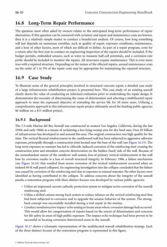
16.6.1 Do Nothing
On some occasions nothing needs to be done for a failed post-tensioned strand. If it is known unequiv-ocally that one strand or possibly two have been accidentally severed, then these strands can be pulledout and not replaced. Section 18.20.4 of the ACI Building Code (ACI Committee 318, 2005) allows thetotal loss of prestress due to unreplaced broken tendons that does not exceed 2% of the total prestress.Thus, for example, in the case of a post-tensioned slab structure that might contain hundreds of tendonsin a single floor, the loss of one strand without replacement would be acceptable and would not beconsidered to have a significant impact on structural integrity.
16.6.2 Tendon Splice or Replacement
Tendon splice or replacement is the most common form of repair to an unbonded concrete structure. Thistype of repair is generally cost effective when the number of tendons to be spliced or replaced is limited,although there have been several notable examples where the tendons in an entire structure have beenreplaced (Aalami and Swanson, 1988). Tendon replacement may include replacement of the strand or oneor more of the anchorages, depending on access for retensioning and anchorage condition. This option isthe repair method of choice if the strand has been severed or if corrosion is localized. The cost of tendonsplicing or replacement can range between $1500 and $5000 per strand, depending on the difficulty of therepair and the number of strands required. If the strand to be spliced or replaced is already severed, thenthe repair is somewhat simplified. If the strand is still tensioned, then the following procedure is required:
• Choose a point in the structure in which the tendon is more accessible. If the location of theproblem and thus the splice point is known, then choose that point. Locate the tendon by use ofa pachometer. In more complicated repairs, radiography or SPR may be warranted.
• Make a shallow saw cut in the concrete surrounding the tendon that defines the limits of theconcrete to be removed.
• Remove the concrete around the tendon by light chipping hammer or jackhammer.• If the strand is to be respliced, it is preferable to install a temporary anchorage. After placing the
temporary anchorage, the strand may then be cut using a grinder. If a temporary anchorage isimpractical, then, exercising extreme caution by making sure no one is in the area of the entiretendon length, the strand may be cut using a grinder. After cutting through just two wires of aseven-wire strand, the strand will yield and then fracture, with an attendant loud noise from theenergy release. In some cases, controlled heating of the strand over a length of several feet maybe preferred. This is the case when sudden detensioning can push out wedges at inaccessibleanchorages, making restressing of the tendons impossible. Heating can result in less shock andmore control in the detensioning process.
• If the existing strand is to be replaced or partially replaced, the strand piece to be removed cannow be pulled from the anchorage. A new strand, coated with a corrosion-inhibiting grease, canthen be threaded through the existing duct. A special type of splicing hardware allows for reten-sioning at the point of splice. This is beneficial when access to the end anchorages does not allowthe use of a standard hydraulic stressing jack.
When stressing has been completed, the concrete can be recast in the excavation. As previously discussed,it is generally preferred to use a concrete of similar strength and modulus as the existing concrete. Exposedreinforcing steel should be cleaned and coated for corrosion protection. Exposed concrete surfaces shouldbe sprayed with water prior to casting concrete. Curing should follow established good practices. In somecases, the entire post-tensioning strand may have to be replaced because of corrosion. In other cases,such as in buildings where access for splicing may be difficult, anchorages at the edge of a member canbecome the splice point. If the existing anchorage is not easily accessible for jacking, then a new anchoragecan be added for ease of constructability.
© 2008 by Taylor & Francis Group, LLC

Structural Concrete Repair 16-19
It is important to emphasize that if the strands are still tensioned and the anchorages are still engaged,do not try to release the stress by jack-hammering around the anchorage. This is very dangerous. Instead,as previously noted in the procedure for splicing, cut a slot in the concrete away from the anchoragezone. Making sure that no one is in the way of the tendon trajectory at the ends of the structure or aboveor below, the strands can be detensioned using a grinder or by heating at the control point. Again, expecta loud noise when several of the wires of the seven-wire strand have been cut. Removal of the anchoragescan begin by first placing a shallow saw cut around the boundary of the anchorage zone. The concretecan then be removed by light chipping. The anchorages and strand can then be removed.
Figure 16.14 shows an arrangement of new corrosion-protected anchorages in place. Note that newmild reinforcement for control of anchorage zone bursting stresses has been placed just in front of theanchorages. In this case, the replacement anchorages are epoxy coated, and the plastic transition trumpetsare attached integrally to the anchorages and the extruded sheathing to prevent water intrusion. Thetrumpet is filled with a corrosion-resistant grease. To expedite retensioning of the replaced tendons, ahigh-early-strength concrete may be used. In no circumstances should it contain calcium chloride as anaccelerator. Many of these high-early-strength concrete materials can gain enough strength (>4000 psi)in 24 hours to allow retensioning the next day.
16.7 Construction Issues
The disruption caused by repairs to an existing structure depends on the degree of deterioration, thetype of the structure being repaired, time of day when the construction is being done, expertise of theselected contractor, and other factors. Disruption to the owners and users of the structure is virtuallyunavoidable. Disruption, however, can be minimized with a carefully thought out and detailed schedulethat is issued by the contractor to the affected parties. Generally, by breaking the project into workableunits that are taken out of service one at a time, completed, then brought back into service is preferableto taking all of the affected areas out of service. Repairs of this nature cost more but allow for continueduse of at least a portion of the structure. Historically, the knowledge level of repair contractors was notwhat might have been expected, but today many more competent and knowledgeable contractors areavailable for conducting specialized concrete repairs. This has resulted in high-quality, cost-competitivestructural concrete repairs.
FIGURE 16.14 New anchorages and bursting steel.
© 2008 by Taylor & Francis Group, LLC
16-20 Concrete Construction Engineering Handbook
16.8 Long-Term Repair Performance
The question most often asked by owners relates to the anticipated long-term performance of repairalternatives. If this question can be answered with certainty and repair and maintenance costs are known,then it is a relatively simple matter to conduct a benefit/cost analysis. Of course, how long somethingwill last depends on numerous variables, such as quality of repair, exposure conditions, maintenance,and a host of other factors, most of which are difficult to define. As part of a repair program, costs fora return after the first year to conduct an engineering inspection of the repairs should be included. If thebudget permits, embedded sensors, such as wires to measure half-cell potentials, and a corrosion-rateprobe should be included to monitor the repairs. All structures require maintenance. This is even moretrue with a repaired structure. Depending on the nature of the effected repairs, annual maintenance costson the order of 1 to 5% of the repair costs may be appropriate for maintaining the repaired structure.
16.9 Case Study
To illustrate some of the general principles involved in structural concrete repair, a detailed case studyof a large infrastructure rehabilitation project is presented here. This case study of an existing seawallclearly shows the value of conducting an informed evaluation prior to undertaking the repair design. Itdemonstrates the necessity of determining the cause of deterioration and selecting a multifaceted repairapproach to meet the expressed objective of extending the service life for 30 more years. Utilizing acomprehensive approach in this infrastructure repair project ultimately saved the funding public agencies$6 million on a $15 million project.
16.9.1 Background
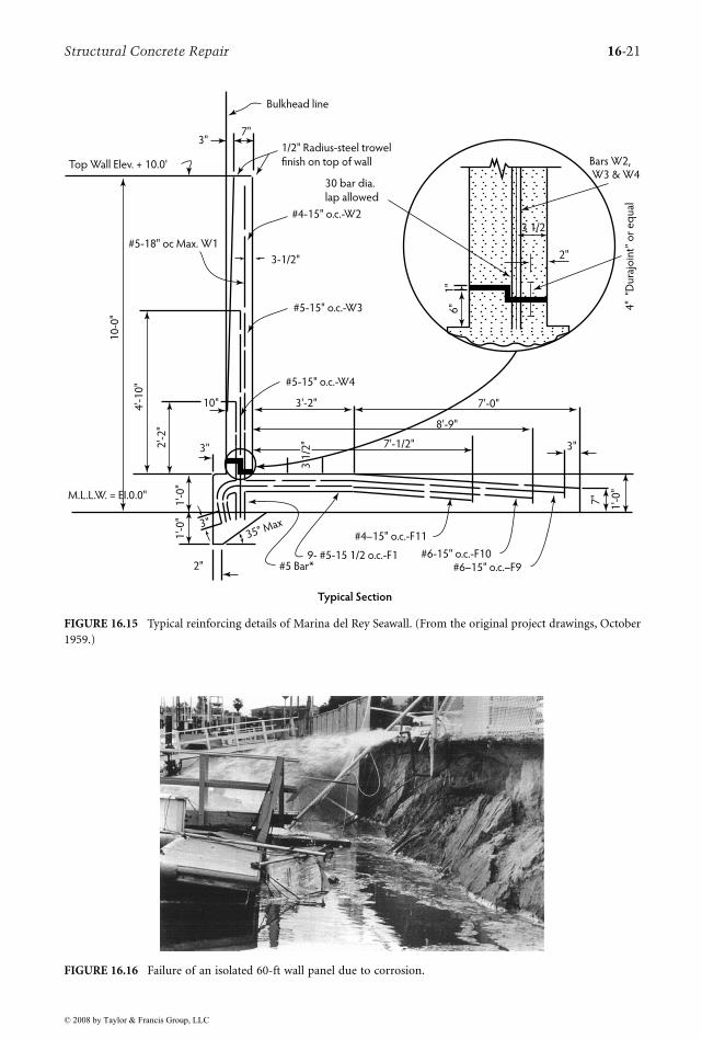
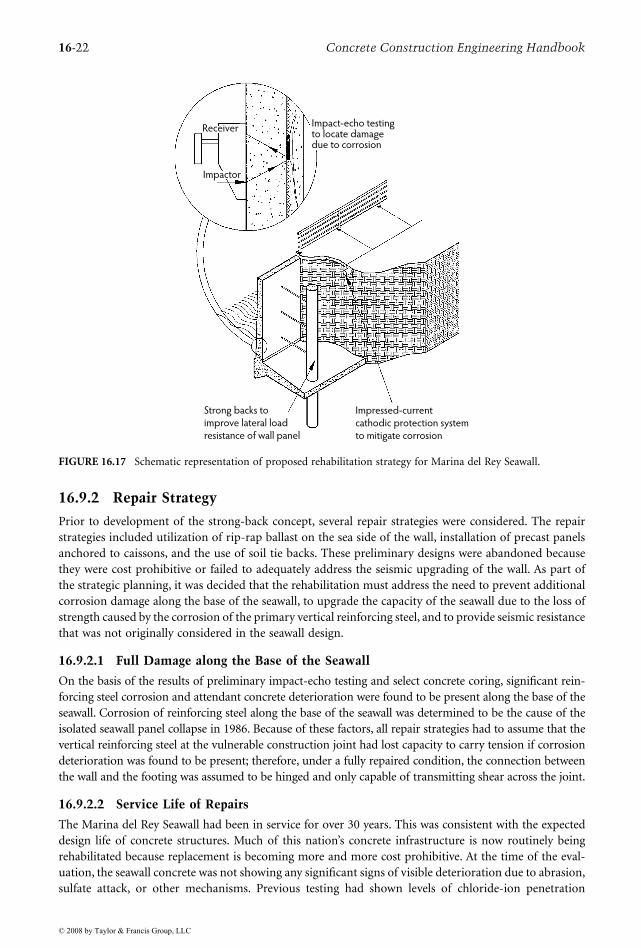
The 7.5-mile Marina del Rey Seawall was constructed in western Los Angeles, California, during the late1950s and early 1960s as a means of reclaiming a low-lying swamp area for dry-land uses. Over $5 billionof infrastructure has developed in and around this area. The original construction was high quality for thetime. The vertical flexural reinforcement in the cantilevered wall has been subjected to aggressive saltwaterexposure, principally through a construction joint located near the base of the wall (see Figure 16.15). Thelong-term exposure to seawater has led to chloride-induced corrosion of the reinforcing steel crossing theconstruction joint and attendant concrete deterioration on the hidden (land) side of the wall. Because ofthe nonredundant nature of the cantilever wall system, loss of primary vertical reinforcement at the wallbase by corrosion results in a loss of overall structural integrity. In February 1986, a failure mechanism(see Figure 16.16) that resulted from severe corrosion of the vertical reinforcement occurred when anisolated 60-ft wall panel collapsed. An engineering investigation into the collapse concluded that the failurewas caused by corrosion of the reinforcing steel due to exposure to natural seawater. No other factors wereidentified as having contributed to the collapse. To address concerns about the integrity of the seawallpanels, a restoration program with three distinct focuses was developed by various public agencies:
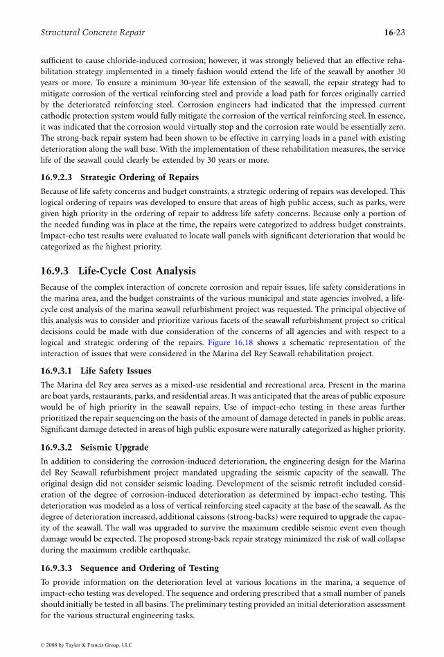
• Utilize an impressed current cathodic protection system to mitigate active corrosion of the seawallreinforcing steel.
• Utilize a drilled caisson strong-back system to reduce reliance on the vertical reinforcing steel thathad been subjected to corrosion and to upgrade the seismic behavior of the system. The strong-back concept was successfully installed during a trial repair in the marina.
• Conduct nondestructive impact-echo testing to locate areas where corrosion damage had occurred.This would allow for categorization of repairs based on the extent of delamination and concernsfor life safety in areas of high public exposure. The impact-echo technique had been proven to besuccessful in locating corrosion-deteriorated areas in the seawall.
Figure 16.17 shows a schematic representation of the multifaceted seawall rehabilitation strategy. Eachof the three distinct focuses of the restoration program is represented in this figure.
© 2008 by Taylor & Francis Group, LLC
Structural Concrete Repair 16-21
FIGURE 16.15 Typical reinforcing details of Marina del Rey Seawall. (From the original project drawings, October1959.)
FIGURE 16.16 Failure of an isolated 60-ft wall panel due to corrosion.
Top Wall Elev. + 10.0'
3"
3" 3"
7"
Bulkhead line
1/2" Radius-steel trowel
finish on top of wall
#4-15" o.c.-W2
#4–15" o.c.-F11
#6–15" o.c.–F9#6-15" o.c.-F109- #5-15 1/2 o.c.-F1
#5-15" o.c.-W3
#5-15" o.c.-W4
3'-2" 7'-0"
7'-1/2"
8'-9"
7"
1'-
0"
2'-
2"
4'-
10
"
10
-0"
M.L.L.W. = EI.0.0"
1'-
0"
1'-
0"
3"
2"
35° Max
#5 Bar*
3 1
/2"
3-1/2"
Typical Section
10"
#5-18" oc Max. W1
Bars W2, W3 & W4
4"
“D
ura
join
t” o
r e
qu
al
3 1/2
2"
30 bar dia.
lap allowed
1"
6"
© 2008 by Taylor & Francis Group, LLC
16-22 Concrete Construction Engineering Handbook
16.9.2 Repair Strategy
Prior to development of the strong-back concept, several repair strategies were considered. The repairstrategies included utilization of rip-rap ballast on the sea side of the wall, installation of precast panelsanchored to caissons, and the use of soil tie backs. These preliminary designs were abandoned becausethey were cost prohibitive or failed to adequately address the seismic upgrading of the wall. As part ofthe strategic planning, it was decided that the rehabilitation must address the need to prevent additionalcorrosion damage along the base of the seawall, to upgrade the capacity of the seawall due to the loss ofstrength caused by the corrosion of the primary vertical reinforcing steel, and to provide seismic resistancethat was not originally considered in the seawall design.
16.9.2.1 Full Damage along the Base of the Seawall
On the basis of the results of preliminary impact-echo testing and select concrete coring, significant rein-forcing steel corrosion and attendant concrete deterioration were found to be present along the base of theseawall. Corrosion of reinforcing steel along the base of the seawall was determined to be the cause of theisolated seawall panel collapse in 1986. Because of these factors, all repair strategies had to assume that thevertical reinforcing steel at the vulnerable construction joint had lost capacity to carry tension if corrosiondeterioration was found to be present; therefore, under a fully repaired condition, the connection betweenthe wall and the footing was assumed to be hinged and only capable of transmitting shear across the joint.
16.9.2.2 Service Life of Repairs
The Marina del Rey Seawall had been in service for over 30 years. This was consistent with the expecteddesign life of concrete structures. Much of this nation’s concrete infrastructure is now routinely beingrehabilitated because replacement is becoming more and more cost prohibitive. At the time of the eval-uation, the seawall concrete was not showing any significant signs of visible deterioration due to abrasion,sulfate attack, or other mechanisms. Previous testing had shown levels of chloride-ion penetration
FIGURE 16.17 Schematic representation of proposed rehabilitation strategy for Marina del Rey Seawall.
Impact-echo testingto locate damagedue to corrosion
Receiver
Impactor
Impressed-current
cathodic protection system
to mitigate corrosion
Strong backs to
improve lateral load
resistance of wall panel
© 2008 by Taylor & Francis Group, LLC
Structural Concrete Repair 16-23
sufficient to cause chloride-induced corrosion; however, it was strongly believed that an effective reha-bilitation strategy implemented in a timely fashion would extend the life of the seawall by another 30years or more. To ensure a minimum 30-year life extension of the seawall, the repair strategy had tomitigate corrosion of the vertical reinforcing steel and provide a load path for forces originally carriedby the deteriorated reinforcing steel. Corrosion engineers had indicated that the impressed currentcathodic protection system would fully mitigate the corrosion of the vertical reinforcing steel. In essence,it was indicated that the corrosion would virtually stop and the corrosion rate would be essentially zero.The strong-back repair system had been shown to be effective in carrying loads in a panel with existingdeterioration along the wall base. With the implementation of these rehabilitation measures, the servicelife of the seawall could clearly be extended by 30 years or more.
16.9.2.3 Strategic Ordering of Repairs
Because of life safety concerns and budget constraints, a strategic ordering of repairs was developed. Thislogical ordering of repairs was developed to ensure that areas of high public access, such as parks, weregiven high priority in the ordering of repair to address life safety concerns. Because only a portion ofthe needed funding was in place at the time, the repairs were categorized to address budget constraints.Impact-echo test results were evaluated to locate wall panels with significant deterioration that would becategorized as the highest priority.
16.9.3 Life-Cycle Cost Analysis
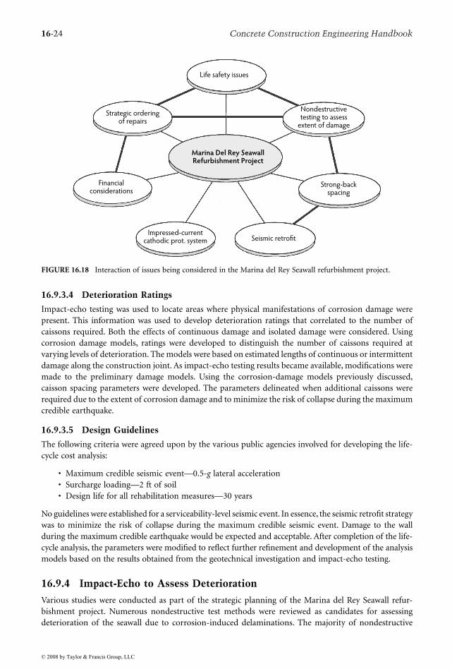
Because of the complex interaction of concrete corrosion and repair issues, life safety considerations inthe marina area, and the budget constraints of the various municipal and state agencies involved, a life-cycle cost analysis of the marina seawall refurbishment project was requested. The principal objective ofthis analysis was to consider and prioritize various facets of the seawall refurbishment project so criticaldecisions could be made with due consideration of the concerns of all agencies and with respect to alogical and strategic ordering of the repairs. Figure 16.18 shows a schematic representation of theinteraction of issues that were considered in the Marina del Rey Seawall rehabilitation project.
16.9.3.1 Life Safety Issues
The Marina del Rey area serves as a mixed-use residential and recreational area. Present in the marinaare boat yards, restaurants, parks, and residential areas. It was anticipated that the areas of public exposurewould be of high priority in the seawall repairs. Use of impact-echo testing in these areas furtherprioritized the repair sequencing on the basis of the amount of damage detected in panels in public areas.Significant damage detected in areas of high public exposure were naturally categorized as higher priority.
16.9.3.2 Seismic Upgrade
In addition to considering the corrosion-induced deterioration, the engineering design for the Marinadel Rey Seawall refurbishment project mandated upgrading the seismic capacity of the seawall. Theoriginal design did not consider seismic loading. Development of the seismic retrofit included consid-eration of the degree of corrosion-induced deterioration as determined by impact-echo testing. Thisdeterioration was modeled as a loss of vertical reinforcing steel capacity at the base of the seawall. As thedegree of deterioration increased, additional caissons (strong-backs) were required to upgrade the capac-ity of the seawall. The wall was upgraded to survive the maximum credible seismic event even thoughdamage would be expected. The proposed strong-back repair strategy minimized the risk of wall collapseduring the maximum credible earthquake.
16.9.3.3 Sequence and Ordering of Testing
To provide information on the deterioration level at various locations in the marina, a sequence ofimpact-echo testing was developed. The sequence and ordering prescribed that a small number of panelsshould initially be tested in all basins. The preliminary testing provided an initial deterioration assessmentfor the various structural engineering tasks.
© 2008 by Taylor & Francis Group, LLC
16-24 Concrete Construction Engineering Handbook
16.9.3.4 Deterioration Ratings
Impact-echo testing was used to locate areas where physical manifestations of corrosion damage werepresent. This information was used to develop deterioration ratings that correlated to the number ofcaissons required. Both the effects of continuous damage and isolated damage were considered. Usingcorrosion damage models, ratings were developed to distinguish the number of caissons required atvarying levels of deterioration. The models were based on estimated lengths of continuous or intermittentdamage along the construction joint. As impact-echo testing results became available, modifications weremade to the preliminary damage models. Using the corrosion-damage models previously discussed,caisson spacing parameters were developed. The parameters delineated when additional caissons wererequired due to the extent of corrosion damage and to minimize the risk of collapse during the maximumcredible earthquake.
16.9.3.5 Design Guidelines
The following criteria were agreed upon by the various public agencies involved for developing the life-cycle cost analysis:
• Maximum credible seismic event—0.5-g lateral acceleration• Surcharge loading—2 ft of soil• Design life for all rehabilitation measures—30 years
No guidelines were established for a serviceability-level seismic event. In essence, the seismic retrofit strategywas to minimize the risk of collapse during the maximum credible seismic event. Damage to the wallduring the maximum credible earthquake would be expected and acceptable. After completion of the life-cycle analysis, the parameters were modified to reflect further refinement and development of the analysismodels based on the results obtained from the geotechnical investigation and impact-echo testing.
16.9.4 Impact-Echo to Assess Deterioration
Various studies were conducted as part of the strategic planning of the Marina del Rey Seawall refur-bishment project. Numerous nondestructive test methods were reviewed as candidates for assessingdeterioration of the seawall due to corrosion-induced delaminations. The majority of nondestructive
FIGURE 16.18 Interaction of issues being considered in the Marina del Rey Seawall refurbishment project.
Life safety issues
Strategic orderingof repairs
Financialconsiderations
Marina Del Rey SeawallRefurbishment Project
Impressed-currentcathodic prot. system
Strong-backspacing
Seismic retrofit
Nondestructivetesting to assess
extent of damage
© 2008 by Taylor & Francis Group, LLC
Structural Concrete Repair 16-25
testing techniques for assessing reinforcing steel corrosion, such as measurement of half-cell corrosionpotentials and chloride-ion content, provide only limited, indirect information about whether or notcorrosion is occurring. These testing measures do not provide an assessment of the amount of corrosiondamage or the degree of concrete deterioration present.
Stress-wave propagation methods known as pulse-echo and pitch-catch were reviewed as candidatesfor detecting damage on the soil side of the wall in the vicinity of the construction joint. These methodshad limitations that made them impractical for use on the seawall as constructed. During the projectdevelopment, the transient stress-wave method known as impact-echo was examined as a possiblecandidate for nondestructively determining the location of corrosion-induced deterioration. This methodwas determined to be well suited for finding flaws in concrete. The reader is referred to Section 16.3.3.1for a description of the impact-echo method.
It is important to note that, although impact-echo is effective for finding flaws in concrete structures,such as the corrosion-induced delaminations on the soil side of the wall near the level of the constructionjoint at the base of the wall, it cannot assess the amount of deterioration in terms of degree of steel-reinforcement corrosion. In this case, impact-echo was used to locate the manifestation of corrosion—that is, the attendant delamination of the concrete caused by reinforcing steel corrosion—but it was notused to assess the degree of corrosion. This implies that, when using the impact-echo method, if adelamination or defect is found it is assumed that the reinforcing steel at this location is in essencecompletely corroded. There could have been some measure of steel area that was still effective, but forcondition-assessment purposes, the steel was assumed to be ineffective for developing a tension forceand thus incapable of carrying moment at the base of the wall. This was a conservative assumption inthe context of the rehabilitation design.
16.9.5 Reliability in Assessing Deterioration
16.9.5.1 Previous Trial Studies on the Seawall
It is generally beneficial in larger projects to conduct trial testing and, in some cases, repairs to provethe veracity of the methods. This approach provides confidence for all parties concerned prior tospending large sums of money. In the case of the seawall project, previous studies that assessed theefficiency of using impact-echo to detect corrosion-induced deterioration on the unobservable soilside of the seawall clearly indicated the veracity of the method. Concrete coring at select locations ofdelaminations located by the impact-echo method demonstrated the reliability of the procedure fordetecting damage.
16.9.5.2 Test Locations
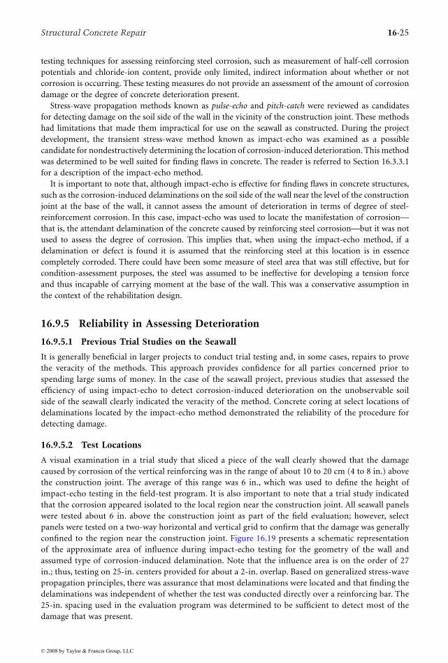
A visual examination in a trial study that sliced a piece of the wall clearly showed that the damagecaused by corrosion of the vertical reinforcing was in the range of about 10 to 20 cm (4 to 8 in.) abovethe construction joint. The average of this range was 6 in., which was used to define the height ofimpact-echo testing in the field-test program. It is also important to note that a trial study indicatedthat the corrosion appeared isolated to the local region near the construction joint. All seawall panelswere tested about 6 in. above the construction joint as part of the field evaluation; however, selectpanels were tested on a two-way horizontal and vertical grid to confirm that the damage was generallyconfined to the region near the construction joint. Figure 16.19 presents a schematic representationof the approximate area of influence during impact-echo testing for the geometry of the wall andassumed type of corrosion-induced delamination. Note that the influence area is on the order of 27in.; thus, testing on 25-in. centers provided for about a 2-in. overlap. Based on generalized stress-wavepropagation principles, there was assurance that most delaminations were located and that finding thedelaminations was independent of whether the test was conducted directly over a reinforcing bar. The25-in. spacing used in the evaluation program was determined to be sufficient to detect most of thedamage that was present.
© 2008 by Taylor & Francis Group, LLC
16-26 Concrete Construction Engineering Handbook
16.9.6 Cathodic Protection
The galvanic corrosion of reinforcing steel in concrete is an electrochemical process in which the rein-forcing steel reacts with water and oxygen to form iron-oxide products (rust). For galvanic corrosion tooccur, four elements must be present. The elements are anodes (locations where corrosion activityoccurs), cathodes (areas that are protected by the corrosion activity at anodes), a metallic path betweenthe anodes and cathodes, and an electrolyte. The metallic path is provided by the horizontal and verticalreinforcing steel mat. Moisture in the soil backfill, seawater, and moist concrete all serve as the electrolyte.The corrosion cell is driven by the differences in electrical potential that exist between the anodic andcathodic areas. Figure 16.20 shows a schematic representation of the electrochemical process of corrosionof reinforcing steel.
Cathodic protection (CP) is an electrochemical technique in which external anodes are added to theelectrochemical cell present in the seawall. The addition of external anodes to the seawall structure resultedin the shift of electrical potentials at the reinforcing steel from anodic (actively corroding) to cathodicvalues (noncorroding). Figure 16.21 shows a schematic representation of both sacrificial anode andimpressed current cathodic protection systems. Two types of cathodic protection systems were consideredfor the Marina del Rey Seawall. A galvanic or sacrificial anode system utilizes metal (typically zinc) anodesattached directly to the reinforcing steel grid. When connected to the reinforcing steel grid, the sacrificialanodes corrode instead of the reinforcing steel. Corrosion of the sacrificial anode results in electronstraveling to the reinforcing steel, which further prevents corrosion of the seawall reinforcing steel.Sacrificial anode systems are best suited to areas of low electrical resistivity or to submerged areas. Animpressed current cathodic protection system is similar to a sacrificial anode system, except that anexternal power supply is used to provide the electrical potential that drives the corrosion cell.
The seawall rehabilitation concept required that the horizontal (temperature and shrinkage) reinforc-ing steel carry the redistributed moments resulting from the caisson installation. This required protectingboth the horizontal and vertical reinforcing steel from long-term corrosion. An impressed currentcathodic protection system was determined to be better suited for long-term corrosion control. This wasbecause of the location of the seawall above the mean low water level and the measured soil resistivities.A successful application of an impressed current cathodic protection system must ensure the electricalcontinuity of all protected areas. Reinforcing steel in both the horizontal and vertical directions was testedto ensure connectivity.
After installation of an impressed current cathodic protection system, the rate of reinforcing steelcorrosion is effectively reduced to zero. This has been proven time and again in actual field applications.To mitigate corrosion, cathodic protection must have an electrolyte present. In the seawall, the seawaterbelow the water table and the moist soil acted as the electrolyte. An electrolyte allows the flow of the
FIGURE 16.19 Influence area of impact-echo test on seawall for anticipated corrosion-induced break delamination.
Probable corrosion-
induced delamination
45°
45°3-1/2"
6”
8"±
9-1/2"
Impact-echo
test location
Impact-echo
test locationSmall zone
of overlap
Zone of influence ≈ 27 in.
© 2008 by Taylor & Francis Group, LLC

Structural Concrete Repair 16-27
impressed current from the sacrificial anode to the reinforcing steel in the seawall. In areas where concretedelaminations have occurred due to corrosion, the cathodic protection system will protect the existingreinforcing steel if sufficient electrolyte is present at these locations. The cathodic protection systemcannot protect areas where an air gap is present between delaminated concrete and the reinforcing steel;however, this condition was not considered likely to be present to any significant degree.
The Marina del Rey Seawall refurbishment project was designed to provide a minimum 30-year lifeextension to the seawall. Accordingly, all facets of the rehabilitation strategy were designed for the ultimateserviceability and durability limit state to reflect a minimum 30-year life cycle. After installation of thecathodic protection system, no further reinforcing steel corrosion was expected to occur; thus, the 30-yearservice life was clearly attainable. The steel was, in essence, kept in its existing condition without furthercorrosion.
16.9.7 Structural AnalysisThis section summarizes the results from various structural analyses that were conducted on a typical60-ft wall panel. Analyses were conducted to assess the integrity of the existing wall without the strong-back system in place for various postulated damage models. Parametric analyses were then conducted fora typical seawall panel that incorporated different combinations of strong-backs (caissons) for postulateddamage models and included the loads resulting from the assumed maximum credible seismic event.
FIGURE 16.20 Schematic of electrochemical corrosion of reinforcing steel in concrete.
FIGURE 16.21 Schematic representation of cathodic protection systems.
Cathode Reaction
O2 + 2H2O + 4e– 4OH–
Reduction
O2 O2
Cathode
e– e–
Current flow
Moist concrete
acts as an electrolyte
Reinforcing steelAnode
Fe++ Fe++
Anode Reaction
Fe Fe++ + 2e–
Oxidation
Metallic conductor Metallic conductor
Electrolyte Electrolyte
Direct-current
power supply– +
Reinforcing steel Reinforcing steelSacrificial anode Anode
Sacrificial Anode Impressed Current
© 2008 by Taylor & Francis Group, LLC

16-28 Concrete Construction Engineering Handbook
16.9.7.1 Integrity of the Typical Existing Panel
Analyses were conducted to assess the integrity of a typical 60-ft wall panel in its current condition forvarious assumed damage models. The threshold damage in terms of the degree of corrosion necessaryto cause collapse of a typical wall panel was then established by examining the results of these analyses:
• Nonlinear analysis model. To assess the integrity of a typical 60-ft seawall panel, as constructedfor various assessed-damage models, a nonlinear analysis of the typical wall section was under-taken. The analytical model used a tangent stiffness formulation. Incremental loads were appliedto the structure, then the incremental displacements and forces were calculated and added tothe previous displacements and forces to obtain the new displacements and forces. The stiffnessmethod is used to calculate incremental displacements from applied loads, and incrementalforces are then computed from the displacements. The model uses a linear formulation that hasbeen modified to include various nonlinear effects. The nonlinearities include second-orderdeflection effects (P-delta), geometric nonlinearity, and material nonlinearity. Analytically, fail-ure occurs when defined material strength limits are exceeded or by the instability of thestructure. Because the seawall was originally designed principally as a cantilever retaining wall,only a typical 1-ft width of wall was required to represent its behavior under lateral load. Figure16.22 shows a schematic representation of the nonlinear model used for the wall. The reinforcingsteel was terminated (cut off) at the appropriate wall height location as indicated in Figure 16.15.The wall taper was also duly accounted for in this analysis. The base of the wall was assumed tobe fixed.
• Loading. Figure 16.23 summarizes the load conditions for which a typical seawall panel wasanalyzed under anticipated actual operating service load conditions. Note that these were not
FIGURE 16.22 Representation of the nonlinear model used for analysis of a typical seawall panel.
Typical section
Typical 1-ft width
of wall modelled
Fiber
Member Section
© 2008 by Taylor & Francis Group, LLC
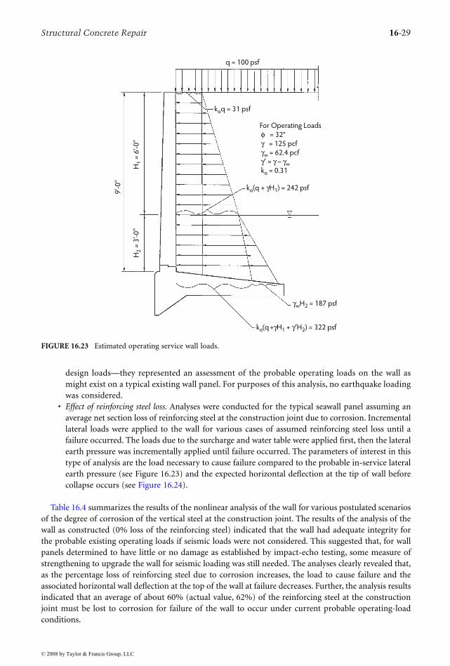
Structural Concrete Repair 16-29
design loads—they represented an assessment of the probable operating loads on the wall asmight exist on a typical existing wall panel. For purposes of this analysis, no earthquake loadingwas considered.
• Effect of reinforcing steel loss. Analyses were conducted for the typical seawall panel assuming anaverage net section loss of reinforcing steel at the construction joint due to corrosion. Incrementallateral loads were applied to the wall for various cases of assumed reinforcing steel loss until afailure occurred. The loads due to the surcharge and water table were applied first, then the lateralearth pressure was incrementally applied until failure occurred. The parameters of interest in thistype of analysis are the load necessary to cause failure compared to the probable in-service lateralearth pressure (see Figure 16.23) and the expected horizontal deflection at the tip of wall beforecollapse occurs (see Figure 16.24).
Table 16.4 summarizes the results of the nonlinear analysis of the wall for various postulated scenariosof the degree of corrosion of the vertical steel at the construction joint. The results of the analysis of thewall as constructed (0% loss of the reinforcing steel) indicated that the wall had adequate integrity forthe probable existing operating loads if seismic loads were not considered. This suggested that, for wallpanels determined to have little or no damage as established by impact-echo testing, some measure ofstrengthening to upgrade the wall for seismic loading was still needed. The analyses clearly revealed that,as the percentage loss of reinforcing steel due to corrosion increases, the load to cause failure and theassociated horizontal wall deflection at the top of the wall at failure decreases. Further, the analysis resultsindicated that an average of about 60% (actual value, 62%) of the reinforcing steel at the constructionjoint must be lost to corrosion for failure of the wall to occur under current probable operating-loadconditions.
FIGURE 16.23 Estimated operating service wall loads.
For Operating Loads
φ = 32°
γ = 125 pcf
γw = 62.4 pcf
γ′ = γ – γw
kα = 0.31
kα(q + γH1) = 242 psf
kα(q +γH1 + γ′H2) = 322 psf
kαq = 31 psf
q = 100 psf
H1 =
6'-
0''
H2 =
3'-
0''
9'-
0''
γwH2 = 187 psf
© 2008 by Taylor & Francis Group, LLC
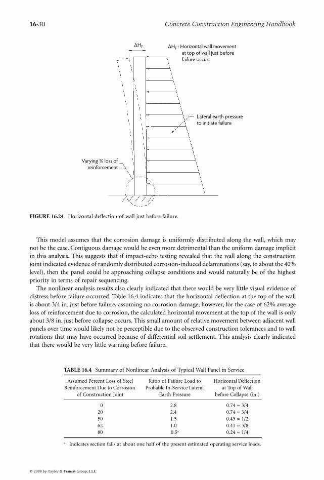
16-30 Concrete Construction Engineering Handbook
This model assumes that the corrosion damage is uniformly distributed along the wall, which maynot be the case. Contiguous damage would be even more detrimental than the uniform damage implicitin this analysis. This suggests that if impact-echo testing revealed that the wall along the constructionjoint indicated evidence of randomly distributed corrosion-induced delaminations (say, to about the 40%level), then the panel could be approaching collapse conditions and would naturally be of the highestpriority in terms of repair sequencing.
The nonlinear analysis results also clearly indicated that there would be very little visual evidence ofdistress before failure occurred. Table 16.4 indicates that the horizontal deflection at the top of the wallis about 3/4 in. just before failure, assuming no corrosion damage; however, for the case of 62% averageloss of reinforcement due to corrosion, the calculated horizontal movement at the top of the wall is onlyabout 3/8 in. just before collapse occurs. This small amount of relative movement between adjacent wallpanels over time would likely not be perceptible due to the observed construction tolerances and to wallrotations that may have occurred because of differential soil settlement. This analysis clearly indicatedthat there would be very little warning before failure.
FIGURE 16.24 Horizontal deflection of wall just before failure.
TABLE 16.4 Summary of Nonlinear Analysis of Typical Wall Panel in Service
Assumed Percent Loss of Steel Reinforcement Due to Corrosion
of Construction Joint
Ratio of Failure Load to Probable In-Service Lateral
Earth Pressure
Horizontal Deflection at Top of Wall
before Collapse (in.)
0 2.8 0.74 ≈ 3/420 2.4 0.74 ≈ 3/450 1.5 0.45 ≈ 1/262 1.0 0.41 ≈ 3/880 0.5a 0.24 ≈ 1/4
a Indicates section fails at about one half of the present estimated operating service loads.
∆HF : Horizontal wall movement
at top of wall just before
failure occurs
∆HF
Lateral earth pressure
to initiate failure
Varying % loss of
reinforcement
© 2008 by Taylor & Francis Group, LLC
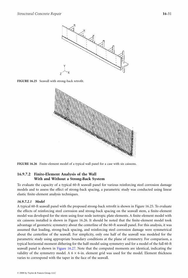
Structural Concrete Repair 16-31
16.9.7.2 Finite-Element Analysis of the Wall With and Without a Strong-Back System
To evaluate the capacity of a typical 60-ft seawall panel for various reinforcing steel corrosion damagemodels and to assess the effect of strong-back spacing, a parametric study was conducted using linearelastic finite-element analysis techniques.
16.9.7.2.1 ModelA typical 60-ft seawall panel with the proposed strong-back retrofit is shown in Figure 16.25. To evaluatethe effects of reinforcing steel corrosion and strong-back spacing on the seawall stem, a finite-elementmodel was developed for the stem using four node isotropic plate elements. A finite-element model withsix caissons installed is shown in Figure 16.26. It should be noted that the finite-element model tookadvantage of geometric symmetry about the centerline of the 60-ft seawall panel. For this analysis, it wasassumed that loading, strong-back spacing, and reinforcing steel corrosion damage were symmetricalabout the centerline of the seawall. For simplicity, only one half of the seawall was modeled for theparametric study using appropriate boundary conditions at the plane of symmetry. For comparison, atypical horizontal moment dithering for the half-model using symmetry and for a model of the full 60-ftseawall panel is shown in Figure 16.27. Note that the computed moments are identical, indicating thevalidity of the symmetry model. A 6 × 6-in. element grid was used for the model. Element thicknessvaries to correspond with the taper in the face of the seawall.
FIGURE 16.25 Seawall with strong-back retrofit.
FIGURE 16.26 Finite-element model of a typical wall panel for a case with six caissons.
Y
XZ
© 2008 by Taylor & Francis Group, LLC
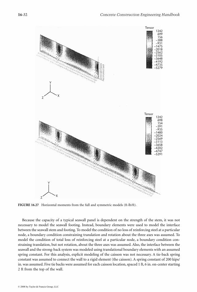
16-32 Concrete Construction Engineering Handbook
Because the capacity of a typical seawall panel is dependent on the strength of the stem, it was notnecessary to model the seawall footing. Instead, boundary elements were used to model the interfacebetween the seawall stem and footing. To model the condition of no loss of reinforcing steel at a particularnode, a boundary condition constraining translation and rotation about the three axes was assumed. Tomodel the condition of total loss of reinforcing steel at a particular node, a boundary condition con-straining translation, but not rotation, about the three axes was assumed. Also, the interface between theseawall and the strong-back system was modeled using translational boundary elements with an assumedspring constant. For this analysis, explicit modeling of the caisson was not necessary. A tie-back springconstant was assumed to connect the wall to a rigid element (the caisson). A spring constant of 200 kips/in. was assumed. Five tie backs were assumed for each caisson location, spaced 1 ft, 6 in. on-center starting2 ft from the top of the wall.
FIGURE 16.27 Horizontal moments from the full and symmetric models (ft-lb/ft).
Tensor1242
699156
–388–931
–1475–2018–2562–3105–3648–4192–4735–5279
Tensor1242
698154
–391–935
–1480–2024–2569–3113–3658–4202–4747–5291
Y
XZ
Y
XZ
© 2008 by Taylor & Francis Group, LLC
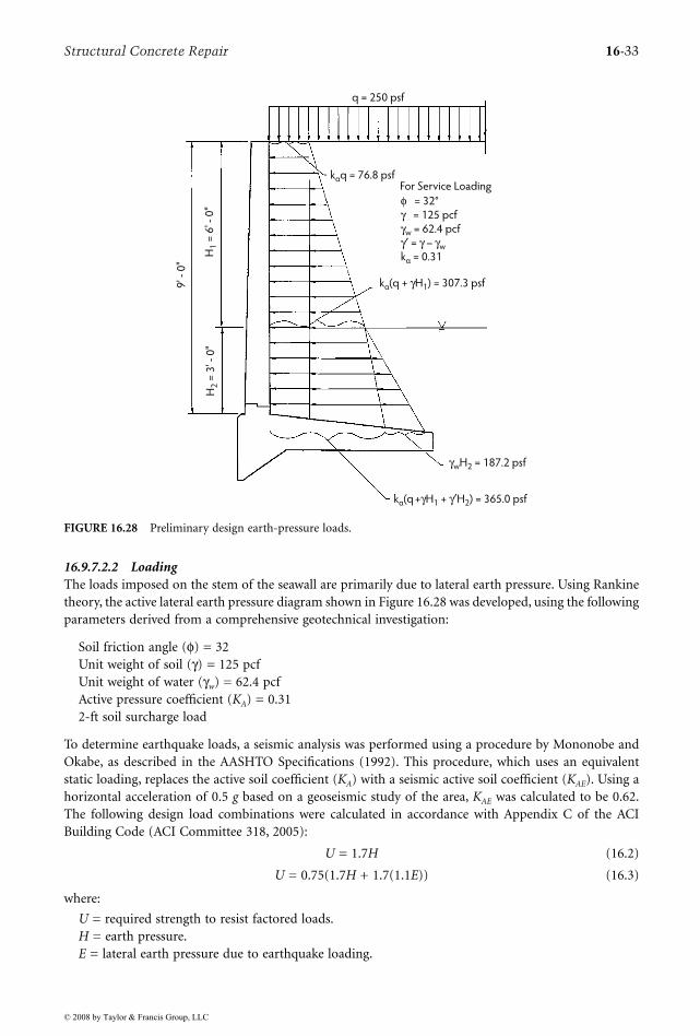
Structural Concrete Repair 16-33
16.9.7.2.2 LoadingThe loads imposed on the stem of the seawall are primarily due to lateral earth pressure. Using Rankinetheory, the active lateral earth pressure diagram shown in Figure 16.28 was developed, using the followingparameters derived from a comprehensive geotechnical investigation:
Soil friction angle (φ) = 32Unit weight of soil (γ) = 125 pcfUnit weight of water (γw) = 62.4 pcfActive pressure coefficient (KA) = 0.312-ft soil surcharge load
To determine earthquake loads, a seismic analysis was performed using a procedure by Mononobe andOkabe, as described in the AASHTO Specifications (1992). This procedure, which uses an equivalentstatic loading, replaces the active soil coefficient (KA) with a seismic active soil coefficient (KAE). Using ahorizontal acceleration of 0.5 g based on a geoseismic study of the area, KAE was calculated to be 0.62.The following design load combinations were calculated in accordance with Appendix C of the ACIBuilding Code (ACI Committee 318, 2005):
U = 1.7H (16.2)
U = 0.75(1.7H + 1.7(1.1E)) (16.3)
where:
U = required strength to resist factored loads.H = earth pressure.E = lateral earth pressure due to earthquake loading.
FIGURE 16.28 Preliminary design earth-pressure loads.
For Service Loading
φ = 32°
γ = 125 pcf
γw = 62.4 pcf
γ′ = γ – γw
kα = 0.31
kα(q + γH1) = 307.3 psf
kα(q +γH1 + γ′H2) = 365.0 psf
kαq = 76.8 psf
q = 250 psf
H1 =
6' -
0"
H2 =
3' -
0"
9' -
0"
γwH2 = 187.2 psf
© 2008 by Taylor & Francis Group, LLC

16-34 Concrete Construction Engineering Handbook
The seismic load combination in Equation 16.3 resulted in forces approximately 60% larger than theload combination in Equation 16.2, which considers only the static lateral earth pressure. Thus, the loadcombination in Equation 16.3 governed the analysis. The appropriate load combinations were used inconjunction with the lateral earth pressure diagram shown in Figure 16.28 to determine the pressureloads used in the finite-element analysis.
16.9.7.2.3 Wall CapacitiesMoment and shear capacities were calculated for the stem of the seawall in accordance with the ACIBuilding Code and are summarized in Table 16.5. These capacities were calculated using the reinforcingsteel details shown on the original plans, and f′ = 4000 psi and fy = 40,000 psi. Review of the originalconstruction records indicated a concrete strength of 3000 psi as used in the original seawall design. Theresults of compressive-strength tests conducted during the field investigation indicated an average com-pressive strength of 4400 psi for the concrete at the time of the evaluation some 35 years later. These testresults justified the use of 4000 psi as the in situ concrete compressive strength for the repair design.
16.9.7.2.4 Analysis ResultsVarious combinations of reinforcing steel corrosion damage scenarios and strong-back spacing were ana-lyzed using the finite-element model and load combinations previously discussed. A summary of the casesanalyzed is presented in Table 16.6. The results of each analysis case were examined and compared withthe moment and shear capacities listed in Table 16.5. Vertical and horizontal shears and moments wereexamined separately, similar to the ACI analysis procedures used for two-way slab design. Sample outputsof horizontal and vertical moments are shown in Figure 16.29 and Figure 16.30, respectively, for Case 8(six strong-backs, 100% corrosion of vertical reinforcing steel, and load combination (Equation 16.2).
Negative horizontal moments that occur at strong-back locations were redistributed, as allowed bySection 8.4 of the ACI Building Code. A maximum redistribution limit of 40% was also examined inlieu of the more restrictive 20% limit imposed by ACI. With the lower reinforcement ratio of thehorizontal reinforcing steel, it was believed that the wall would exhibit adequate ductility to allow thislarger redistribution limit with the caissons in place. For the final design, a detailed moment-curvatureanalysis of the wall ductility generally confirmed this assumption.
TABLE 16.5 Moment and Shear Capacities of a Typical Undamaged Wall Panel
Inches
Vertical Moment Horizontal Moment
Shear(lb/ft)
Negative(ft-lb/ft)
Positive(ft-lb/ft)
Negative(ft-lb/ft)
Positive(ft-lb/ft)
0 –12,229 6292 –3636 2534 41906 –11899 6292 –3531 2534 3230
12 –11569 6292 –3426 2534 398018 –7133 6292 –3321 2534 387024 –6928 6292 –3216 2534 376030 –6723 4058 –3111 2534 366036 –6518 4058 –3006 2534 355042 –6313 4058 –2901 2534 344048 –2442 4058 –2796 2534 333054 –2362 1642 –2691 2534 323060 –2282 1642 –2586 2534 312066 –2202 1642 –2481 2534 301072 –2122 1642 –2376 2534 290078 –2042 1642 –2271 2534 280084 –1962 1642 –2166 2534 269090 –1882 1642 –2061 2534 258096 –1802 1642 –1956 2534 2470
102 –1722 1642 –1851 2534 2370108 –1642 1642 –1746 2534 2260
© 2008 by Taylor & Francis Group, LLC
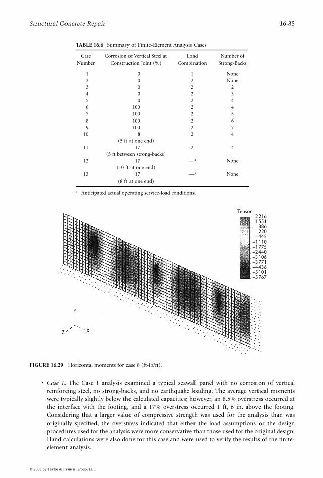
Structural Concrete Repair 16-35
• Case 1. The Case 1 analysis examined a typical seawall panel with no corrosion of verticalreinforcing steel, no strong-backs, and no earthquake loading. The average vertical momentswere typically slightly below the calculated capacities; however, an 8.5% overstress occurred atthe interface with the footing, and a 17% overstress occurred 1 ft, 6 in. above the footing.Considering that a larger value of compressive strength was used for the analysis than wasoriginally specified, the overstress indicated that either the load assumptions or the designprocedures used for the analysis were more conservative than those used for the original design.Hand calculations were also done for this case and were used to verify the results of the finite-element analysis.
TABLE 16.6 Summary of Finite-Element Analysis Cases
Case Number
Corrosion of Vertical Steel at Construction Joint (%)
Load Combination
Number of Strong-Backs
1 0 1 None2 0 2 None3 0 2 24 0 2 35 0 2 46 100 2 47 100 2 58 100 2 69 100 2 7
10 8(5 ft at one end)
2 4
11 17(5 ft between strong-backs)
2 4
12 17(10 ft at one end)
—a None
13 17(8 ft at one end)
—a None
a Anticipated actual operating service-load conditions.
FIGURE 16.29 Horizontal moments for case 8 (ft-lb/ft).
Tensor22161551
886220
–445–1110–1775–2440–3106–3771–4436–5101–5767
Y
XZ
© 2008 by Taylor & Francis Group, LLC
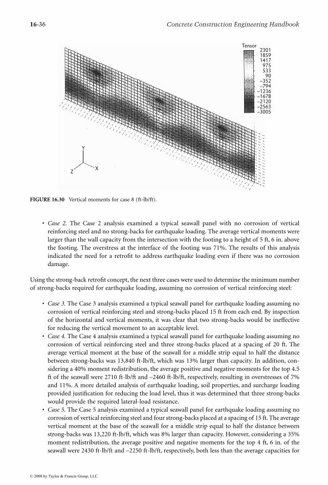
16-36 Concrete Construction Engineering Handbook
• Case 2. The Case 2 analysis examined a typical seawall panel with no corrosion of verticalreinforcing steel and no strong-backs for earthquake loading. The average vertical moments werelarger than the wall capacity from the intersection with the footing to a height of 5 ft, 6 in. abovethe footing. The overstress at the interface of the footing was 71%. The results of this analysisindicated the need for a retrofit to address earthquake loading even if there was no corrosiondamage.
Using the strong-back retrofit concept, the next three cases were used to determine the minimum numberof strong-backs required for earthquake loading, assuming no corrosion of vertical reinforcing steel:
• Case 3. The Case 3 analysis examined a typical seawall panel for earthquake loading assuming nocorrosion of vertical reinforcing steel and strong-backs placed 15 ft from each end. By inspectionof the horizontal and vertical moments, it was clear that two strong-backs would be ineffectivefor reducing the vertical movement to an acceptable level.
• Case 4. The Case 4 analysis examined a typical seawall panel for earthquake loading assuming nocorrosion of vertical reinforcing steel and three strong-backs placed at a spacing of 20 ft. Theaverage vertical moment at the base of the seawall for a middle strip equal to half the distancebetween strong-backs was 13,840 ft-lb/ft, which was 13% larger than capacity. In addition, con-sidering a 40% moment redistribution, the average positive and negative moments for the top 4.5ft of the seawall were 2710 ft-lb/ft and –2460 ft-lb/ft, respectively, resulting in overstresses of 7%and 11%. A more detailed analysis of earthquake loading, soil properties, and surcharge loadingprovided justification for reducing the load level, thus it was determined that three strong-backswould provide the required lateral-load resistance.
• Case 5. The Case 5 analysis examined a typical seawall panel for earthquake loading assuming nocorrosion of vertical reinforcing steel and four strong-backs placed at a spacing of 15 ft. The averagevertical moment at the base of the seawall for a middle strip equal to half the distance betweenstrong-backs was 13,220 ft-lb/ft, which was 8% larger than capacity. However, considering a 35%moment redistribution, the average positive and negative moments for the top 4 ft, 6 in. of theseawall were 2430 ft-lb/ft and –2250 ft-lb/ft, respectively, both less than the average capacities for
FIGURE 16.30 Vertical moments for case 8 (ft-lb/ft).
Tensor230118591417
975533
90–352–794
–1236–1678–2120–2563–3005
Y
XZ
© 2008 by Taylor & Francis Group, LLC
Structural Concrete Repair 16-37
these regions. Although the vertical moment at the base is slightly overstressed, the horizontalmoment capacity was considered adequate when considering a 35% moment redistribution. Basedon analysis of the results for Case 5, the installation of a minimum of four strong-backs at eachtypical panel would be required for the assumed earthquake loading.
The next four cases were used to determine the maximum number of strong-backs required for earth-quake loading assuming 100% corrosion of the vertical reinforcing steel:
• Case 6. The Case 6 analysis examined a typical seawall panel for earthquake loading assuming100% corrosion of the vertical reinforcing steel and four strong-backs placed with a spacing of 15ft. By inspection of the positive and negative horizontal moments, it was clear that both weresignificantly overstressed.
• Case 7. The Case 7 analysis examined a typical seawall panel for earthquake loading assuming100% corrosion of the vertical reinforcing steel and five strong-backs placed at a spacing of 12 ft.As with Case 6, inspection of the positive and negative horizontal moments made it clear thatboth were significantly overstressed.
• Case 8. The Case 8 analysis examined a typical seawall panel for earthquake loading assuming100% corrosion of the vertical reinforcing steel and six strong-backs placed at a spacing of 10ft. The average positive and negative moments for the top 4 ft, 6 in. of the seawall assuming a40% redistribution were 3500 ft-lb/ft and –2340 ft-lb/ft, respectively, resulting in overstresses of38% and 6%. Considering the level of overstress of both the horizontal positive and negativemoments, the installation of six strong-backs would not be sufficient to resist the loadingsassumed in the preliminary study. Again, it was later determined that six strong-backs was themaximum number required for a given 60-ft seawall panel when more refined soil parametersbecame available.
• Case 9. The Case 9 analysis examined a typical seawall for earthquake loading assuming 100%corrosion of the vertical reinforcing steel and seven strong-backs placed at a spacing of 8 ft, 6 in.The average positive and negative moments for the top 4 ft, 6 in. of the seawall using a 35%redistribution were 2480 ft-lb/ft and –2000 ft-lb/ft, respectively, both less than the average capac-ities for these regions.
Based on analysis of the results for Case 9, a maximum number of seven strong-backs would berequired for the assumed earthquake loading; therefore, it was determined that for the loading conditionseach seawall panel required the installation of seven strong-backs, depending on the amount of verticalreinforcing steel corrosion. This requirement was relaxed to three to six caissons on the basis of the resultsfrom the soil investigation and refinements in the seismic and surcharge loadings. Case 10 and Case 11examined the effect of a continuous strip of reinforcing steel corrosion damage on strong-back spacing:
• Case 10. The Case 10 analysis examined a typical seawall panel for earthquake loading assuming5 ft of continuous (8%) corrosion of the vertical reinforcing steel at the end of a panel and fourstrong-backs placed at a spacing of 15 ft. Based on the analysis of this case, 5 ft of continuouscorrosion of the vertical steel at the end of a panel required an additional strong-back.
• Case 11. The Case 11 analysis examined a typical seawall panel for earthquake loading assuming5 ft of continuous (8%) corrosion of the vertical reinforcing steel, centered between two strong-backs, assuming four strong-backs placed at a spacing of 15 ft. The average positive and negativemoments for the top 4 ft, 6 in. of the seawall using a 40% redistribution were 3850 ft-lb/ft and–2380 ft-lb/ft, respectively, resulting in overstresses of 52% and 7%. Considering this level ofoverstress of both the horizontal positive and negative moments, it was determined that 5 ft ofcontinuous damage between strong-backs required a strong-back spacing of less than 15 ft.
The Case 12 and Case 13 analyses examined a typical seawall panel with no strong-backs using theanticipated actual operating service load conditions to determine the amount of continuous vertical
© 2008 by Taylor & Francis Group, LLC
16-38 Concrete Construction Engineering Handbook
reinforcing steel damage at one end that would lead to a failure (“unzipping”) of the panel. In this case,failure would occur by progressive yielding of the noncorroded vertical reinforcing adjacent to thedamaged area that continued to the opposite end of the panel.
• Case 12. The Case 12 analysis examined 10 ft of continuous damage from one end. On the basisof the results of this analysis, it was determined that continuous damage of 10 ft or more wassufficient to cause a progressive failure of the seawall panel.
• Case 13. The Case 13 analysis used the same assumption as Case 12, except that continuousdamage of 8 ft from one end was examined. On the basis of the results of this analysis, it wasdetermined that continuous damage of less than 8 ft would not cause a progressive failure of theseawall panel.
16.9.8 Life Safety Implications
To address life safety concerns, a multifaceted restoration program was developed by various local andstate agencies. The plan utilized an impressed current cathodic protection system to mitigate activecorrosion of the reinforcing steel. A strong-back system was developed to upgrade the seismic behaviorof the seawall and the integrity lost by corrosion of the reinforcing steel. A minimum of three caissonswas determined to be necessary to upgrade the seismic capacity of the seawall to satisfy current building-code requirements. The number of additional caissons was directly proportional to the extent of corrosiondamage along the base of the seawall. For the case of full damage along the seawall (worst-case scenario),analysis indicated that six caissons were required to provide satisfactory capacity. To determine the extentof the corrosion damage along the base of the seawall, a program of nondestructive impact-echo testingwas conducted. Because of budget constraints of the various municipal and state agencies involved,guidelines for prioritization of the repairs were needed. These guidelines helped to ensure that life safetyconsiderations were of paramount importance with respect to the prioritization of repairs.
The budget constraints of the municipal and state agencies involved in the Marina del Rey Seawallrestoration program required a prioritization of repairs based on two criteria: (1) the extent of damagealong the base of the seawall panel, and (2) the degree of public exposure of an individual seawall panel.To simplify the categorization of public exposure, use of two categories was proposed. A public exposurecategorized as high was limited to areas where a seawall panel collapse would result in a high probabilityof personal injury. All other areas were categorized as low exposures.
Analysis indicated that a 60% loss of reinforcing steel might result in the collapse of the seawall panelat its actual operating service load levels. This was based on the assumption of uniformly distributedcorrosion damage across the base of the seawall. Analysis also indicated that contiguous damage fromthe end of a seawall panel was more severe in nature than uniform damage. For the purposes ofcategorizing the extent of damage, the adoption of a dual-criteria classification was proposed. Theclassification assigned the panels to one of three categories, as described in Table 16.7. Wall panels wereplaced into the appropriate damage category if either criteria in Table 16.7 was satisfied. The use of 40%of total wall damage was recommended as the maximum allowable to provide some additional measureof conservatism. During the impact-echo testing, panels classified in the high-damage category wereimmediately brought to the attention of the public agencies involved.
Due to the financial considerations, a phased construction schedule was proposed. To minimize publicexposure to the potential collapse of a seawall panel, repairs in areas of high public exposure with highpriority and intermediate damage levels were classified as the highest priority. Other areas were catego-rized into two additional groups based on public exposure and degree of deterioration. Table 16.8 specifiesthe repair prioritization groupings that were made.
16.9.9 Cost Savings
Structural analysis of the Marina del Rey Seawall indicated that the number of caissons required toupgrade the capacity of the seawall for seismic loads was directly related to the amount of corrosion
© 2008 by Taylor & Francis Group, LLC
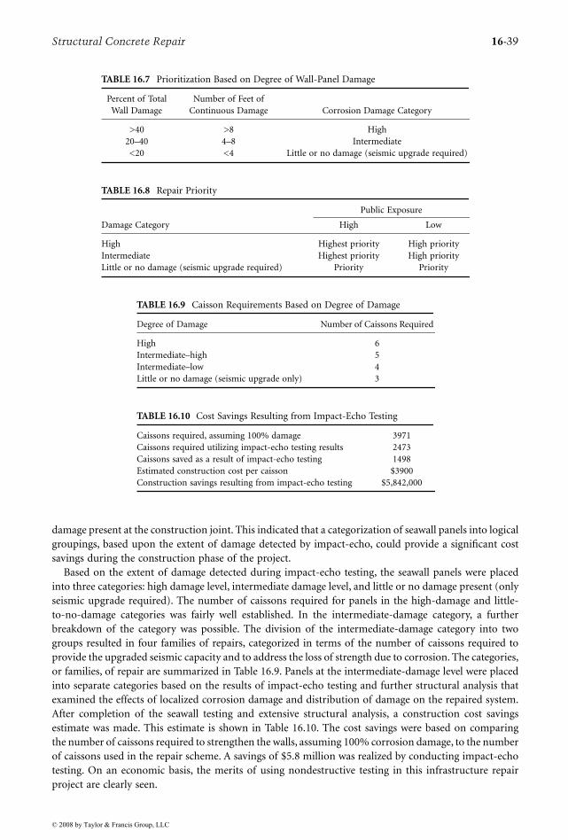
Structural Concrete Repair 16-39
damage present at the construction joint. This indicated that a categorization of seawall panels into logicalgroupings, based upon the extent of damage detected by impact-echo, could provide a significant costsavings during the construction phase of the project.
Based on the extent of damage detected during impact-echo testing, the seawall panels were placedinto three categories: high damage level, intermediate damage level, and little or no damage present (onlyseismic upgrade required). The number of caissons required for panels in the high-damage and little-to-no-damage categories was fairly well established. In the intermediate-damage category, a furtherbreakdown of the category was possible. The division of the intermediate-damage category into twogroups resulted in four families of repairs, categorized in terms of the number of caissons required toprovide the upgraded seismic capacity and to address the loss of strength due to corrosion. The categories,or families, of repair are summarized in Table 16.9. Panels at the intermediate-damage level were placedinto separate categories based on the results of impact-echo testing and further structural analysis thatexamined the effects of localized corrosion damage and distribution of damage on the repaired system.After completion of the seawall testing and extensive structural analysis, a construction cost savingsestimate was made. This estimate is shown in Table 16.10. The cost savings were based on comparingthe number of caissons required to strengthen the walls, assuming 100% corrosion damage, to the numberof caissons used in the repair scheme. A savings of $5.8 million was realized by conducting impact-echotesting. On an economic basis, the merits of using nondestructive testing in this infrastructure repairproject are clearly seen.
TABLE 16.7 Prioritization Based on Degree of Wall-Panel Damage
Percent of Total Wall Damage
Number of Feet of Continuous Damage Corrosion Damage Category
>40 >8 High20–40 4–8 Intermediate<20 <4 Little or no damage (seismic upgrade required)
TABLE 16.8 Repair Priority
Damage Category
Public Exposure
High Low
High Highest priority High priorityIntermediate Highest priority High priorityLittle or no damage (seismic upgrade required) Priority Priority
TABLE 16.9 Caisson Requirements Based on Degree of Damage
Degree of Damage Number of Caissons Required
High 6Intermediate–high 5Intermediate–low 4Little or no damage (seismic upgrade only) 3
TABLE 16.10 Cost Savings Resulting from Impact-Echo Testing
Caissons required, assuming 100% damage 3971Caissons required utilizing impact-echo testing results 2473Caissons saved as a result of impact-echo testing 1498Estimated construction cost per caisson $3900Construction savings resulting from impact-echo testing $5,842,000
© 2008 by Taylor & Francis Group, LLC

16-40 Concrete Construction Engineering Handbook
16.9.10 Conclusions
The Marina del Rey Seawall had been in service as a mixed-use residential and recreational area for over30 years, and $5 billion of infrastructure had been built around the area. To ensure its continuing servicefor at least another 30 years or more, an extensive restoration program was developed to mitigate theongoing corrosion of the seawall reinforcing steel, to upgrade the seismic capacity of the seawall, and torestore the integrity of seawall panels that had been lost due to corrosion. The following are the moresalient conclusions from the presentation of this case study:
• Analysis of the seawall indicated that, with increasing levels of reinforcing steel corrosion, theductility of the wall decreased. At an assumed 60% loss of reinforcing steel due to corrosion atthe seawall base, a failure was possible at the operating service load levels on the seawall. Thehorizontal deflection of the top of the wall prior to failure was determined to be approximately3/8 in. for the case of 60% reinforcing steel loss. This would provide little warning of pendingfailure.
• The finite-element analysis clearly indicated the need for strong-back installation to seismicallyupgrade the seawall panels; however, the number of caissons required beyond the number neces-sary for seismic resistance increased as the amount of corrosion damage increased. Between threeand six caissons were required to provide adequate lateral load resistance depending on the degreeof corrosion damage detected.
• Threshold criteria were established to prioritize the repairs. The categorization was based primarilyon life safety concerns in areas of high public exposure. Seawall panels that were determined tohave a high degree of deterioration and that were located in areas of high public exposure wereclassified as the highest priority.
• On the basis of the cost estimate for caisson installation and the estimated number of panels thatrequired only seismic-capacity upgrades, a substantial cost savings was realized with the perfor-mance of nondestructive impact-echo testing. Some $5.8 million was saved by conducting thistesting.
16.9.11 Reports, Standards, and Guidelines
16.9.11.1 American Concrete Institute (ACI) Reports
ACI 224.1R-93 Causes, Evaluation and Repair of Cracks in Concrete Structures (reapproved 1998)ACI 228.2R-98 Nondestructive Test Methods for Evaluation of Concrete in StructuresACI 364.1R-94 Guide for Evaluation of Concrete Structures Prior to Rehabilitation (reapproved 1999)
16.9.11.2 American Society for Testing and Materials (ASTM) Standards
ASTM C 39 Test Method for Compressive Strength of Cylindrical Concrete SpecimensASTM C 42 Test Method for Obtaining and Testing Drilled Cores and Sawed Beams of ConcreteASTM C 157 Test Method for Length Change of Hardened Hydraulic Cement Mortar and ConcreteASTM C 805 Test Method for Rebound Number in ConcreteASTM C 803 Test Method for Penetration Resistance of Hardened ConcreteASTM C 597 Test Method for Pulse Velocity Through ConcreteASTM C 876 Test Method for Half-Cell Potentials of Uncoated Reinforcing Steel in ConcreteASTM C 856 Standard Practice for Petrographic Examination of Hardened ConcreteASTM C 457 Test Method for Microscopical Determination of Parameters of the Air-Void System in
Hardened ConcreteASTM C 1084 Test Method for Portland Cement Content of Hardened Hydraulic-Cement ConcreteASTM C 642 Test Method for Density, Absorption, and Voids in Hardened ConcreteASTM C 496 Test Method for Splitting Tensile Strength of Cylindrical Concrete SpecimensASTM C 215 Test Method for Fundamental Transverse, Longitudinal, and Torsional Frequencies of
Concrete Specimens
© 2008 by Taylor & Francis Group, LLC
Structural Concrete Repair 16-41
ASTM C 469 Test Method for Static Modulus of Elasticity and Poisson’s Ratio of Concrete in Com-pression
ASTM C 341 Test Method for Length Change of Drilled or Sawed Specimens of Hydraulic-CementMortar and Concrete
ASTM C 1152 Test Method for Acid-Soluble Chloride in Mortar and ConcreteASTM C 1583 Test Method for Tensile Strength of Concrete Surfaces and the Bond or Tensile Strength
of Concrete Repair and Overlay Materials by Direct Tension (Pull-Off Method)ASTM C 1202 Test Method for Electrical Indication of Concrete’s Ability to Resist Chloride Ion Pen-
etrationASTM D 4748 Test Method for Determining the Thickness of Bound Pavement Layers Using Short-
Pulse RadarASTM D 4580 Practice for Measuring Delaminations in Concrete Bridge Decks by SoundingASTM D 4788 Test Method for Deflecting Delaminations in Bridge Decks Using Infrared Thermography
16.9.11.3 International Concrete Repair Institute (ICRI) Documents
Guideline No. 03730 Surface Preparation for the Repair of Deteriorated Concrete Resulting from Rein-forcing Steel Corrosion
Guideline No. 03732 Guide for Selecting and Specifying Surface Preparation for Sealers, Coatings, andPolymer Overlays
Guideline No. 03733 Guide for Selecting and Specifying Materials for Repair Of Concrete SurfacesGuideline No. 03734 Guide for Verifying Field Performance of Epoxy Injection of Concrete Cracks
16.9.11.4 Strategic Highway Research Program (SHRP) Documents
SHRP-C/FR-91-101 Handbook for the Identification of Alkali–Silica Reactivity in Highway StructuresSHRP-S-330 Condition Evaluation of Concrete Bridges Relative to Reinforcement Corrosion,
Volume 8, Procedure ManualSHRP-S-324 Condition Evaluation of Concrete Bridges Relative to Reinforcement Corrosion,
Volume 2, Method for Measuring the Corrosion Rate of Reinforcing SteelSHRP-S/FR-92-108 Condition Evaluation of Concrete Bridges Relative to Reinforcement Corrosion,
Volume 6, Method for Field Determination of Total Chloride Content
16.9.11.5 Repair, Evaluation, Maintenance, and Rehabilitation (REMR) Research Program Reports
Theses reports can be purchased from http://www.ntis.gov/.
REMR-CS-47 Performance Criteria for Concrete Repair Materials, Phase IREMR-CS-57 Performance Criteria for Concrete Repair Materials, Phase II Laboratory ResultsREMR-CS-60 Performance Criteria for Concrete Repair Materials, Phase II Field StudiesREMR-CS-61 An Evaluation of Equipment and Procedures for Tensile Bond Testing of Concrete RepairsREMR-CS-62 Performance Criteria for Concrete Repair Materials, Phase II Summary Report
References
Aalami, B.O. and Swanson, D.T. 1988. Innovative rehabilitation of a parking structure. Concrete Int. 10(2),30–35.
AASHTO. 1992. Standard Specification for Highway Bridges, 15th ed. American Association of StateHighway and Transportation Officials, Washington, D.C.
ACI. 2002. Concrete Repair Manual, 2nd ed. American Concrete Institute, Farmington Hills, MI.ACI Committee 224. 1998. Causes, Evaluation, and Repair of Cracks in Concrete Structures, ACI 224.1R-
93. American Concrete Institute, Farmington Hills, MI.
© 2008 by Taylor & Francis Group, LLC
16-42 Concrete Construction Engineering Handbook
ACI Committee 318. 2005. Building Code Requirements for Reinforced Concrete, ACI 318-05; Commentary,ACI 318R-05. American Concrete Institute, Farmington Hills, MI.
ACI Committee 318. 2008. Building Code Requirements for Structural Concrete, ACI 318-08. AmericanConcrete Institute, Farmington Hills, MI.
ASCE. 2000. Guideline for Structural Assessment of Existing Buildings, SEI/ASCE 11-99. American Societyof Civil Engineers, Reston, VA.
Emmons, P.H. 1994. Concrete Repair and Maintenance Illustrated, 295 pp. R.S. Means, Kingston, MA.Emmons, P.H., Vaysburd, A.M., and McDonald, J.E. 1994. Concrete repair in the future turn of the
century: any problems? Concrete Int., 16(3), 42–49.ICRI. 1996. Guide for Selecting and Specifying Materials for Repair of Concrete Surfaces, ICRI Technical
Guidelines No. 03733. International Concrete Repair Institute, Des Plaines, IL.MacGregor, J.G. 1976. Safety and limit states design for reinforced concrete. Can. J. Civ. Eng., 3(4),
484–513.McDonald, J.E., Vaysburd, A.M., Emmons, P.H., Poston, R.W., and Kesner, K.E. 2002. Selecting durable
repair materials: performance criteria summary. Concrete Int., 24(1), 37–44.Natesaiyer, K. and Hover, K.C. 1988. In situ identification of ASR products in concrete. Cement Concrete
Res., 18, 455–463.Natesaiyer, K. and Hover, K.C. 1989. Some field strategies of the new in situ method for identification
of alkali–silica reaction products in concrete. Cement Concrete Res., 19, 770–778.Poston, R.W. and Irshad, M. 1996a. Load tests: externally post-tensioned bridge girders, Parts I and II.
Concrete Int., 18(8), 39–43.Sansalone, M. and Carino, N.J. 1986. Impact-Echo: A Method for Flow Detection in Concrete Using Transient
Stress Waves, NBSIR 86–3452, 222 pp. National Bureau of Standards, Gaithersburg, MD.Sansalone, M. and Carino, N.J. 1988. Impact-echo method: detecting honeycombing, the depth of
surface-opening cracks, and ungrouted ducts. Concrete Int., 10(4), 38–46.Strategic Development Council. 1996. Vision 2020: A Vision for the Concrete Repair Protection and
Strengthening Industry, http://www.concretesdc.org/projects/focaltopics_current.htm.TRB. 1986. Strategic Highway Program Research Plans, final report, NCHRP Project 20-20, TRA 4-1–TRA
4-60. Transportation Research Board, Washington, D.C.Wolkomir, R. 1994. Inside the lab and out, concrete is more than it’s cracked up to be. Smithsonian,
24(10), 22–31.
© 2008 by Taylor & Francis Group, LLC
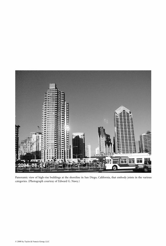
Panoramic view of high-rise buildings at the shoreline in San Diego, California, that embody joints in the variouscategories. (Photograph courtesy of Edward G. Nawy.)
© 2008 by Taylor & Francis Group, LLC