Embed Size (px)
Citation preview
16th Int Symp on Applications of Laser Techniques to Fluid Mechanics Lisbon, Portugal, 09-12 July, 2012
- 1 -
Structural Characteristics of a Heated Jet in Cross-Flow Emanating from a
Raised, Circular Stack†
Blake Everett Johnson1,3*, Gregory S. Elliott1,2, Kenneth T. Christensen1,2
1: Mechanical Science and Engineering, University of Illinois, Urbana, IL, USA 2: Aerospace Engineering, University of Illinois, Urbana, IL, USA
3: Presently: Department of Aerospace Engineering, Iowa State University, Ames, Iowa, USA *correspondent author: [email protected]
Abstract The structural characteristics of a jet heated to 425 K and emitted from a raised, circular stack into a 300 K cross-flow were studied via cross-plane sPIV measurements at multiple streamwise locations downstream of the stack exit. Similar measurements of an unheated jet at equivalent Reynolds number and similar blowing ratio provided a baseline of comparison for the heated case. Instantaneous velocity fields for the heated and unheated jets were marked by intense, small-scale vortices and only a weak indication of a counter-rotating vortex pair (CVP). Upon filtering to recover only the large-scale flow features, the imprint of the CVP was clearly discerned in the instantaneous fields. The CVP of the heat jet was stronger as well as larger and advected further into the cross flow compared to that of the unheated jet. 1. Introduction Many research studies have focused on various aspects of jets into cross-flows (JICFs) given their occurrence in an abundance of technologically-relevant applications and potential for environmental impact. Many of these applications involve non-circular nozzle cross-sections, elevated nozzles (the so-called “stack” configuration) and often strong temperature differences between the jet and cross-flow fluids. Early research on these effuent-into-cross-flow scenarios focused on chimney plumes and sought chiefly to quantify the dispersion of pollutants, whether in the form of smoke or steam from exhaust stacks into the atmosphere (Slawson and Csanady, 1967) or waste liquids into lakes and rivers (Anderson et al., 1973). Conversely, heated jets in cross-flow (HJICFs) in engineering practice may be encountered in power plants, where pressurized steam used to power turbines is vented from tall exhaust stacks, for example. Other engineering applications of JICFs include cooling and control in propulsion systems (Margason, 1993).
Natural HJICFs include volcanic eruptions and geysers, where dispersion of the jet fluid and other pollutants may have powerful impact on the terrestrial environment, even affecting global climate patterns; and deep oceanic hydrothermal vents, which have attracted the attention of biologists due to the discovery of simple and complex life forms in such extreme environments. Within the research community, strong attention has been devoted to the simple case of an unheated transverse jet emitting from a circular orifice set flush with the lower cross-flow boundary. The most prominent structure in the far-field of the jet is the counter-rotating vortex pair (CVP), which is responsible for a dynamic mixing of the jet and entrained cross-flow fluid. Much speculation has been made as to the generation of the CVP, with some studies suggesting jet boundary-layer vorticity as its source (Haven and Kurosaka, 1997) and others proposing a folding of the shear-layer vortices just above the point of injection to initiate the CVP (Kelso et al., 1996; New et al., 2003; Gutmark et al., 2008). These shear-layer vortices have been observed frequently and arise in a manner reminiscent of Kelvin−Helmholtz instabilities due to the interaction of streams of fluid with differing velocities. The shear-layer vortices have been observed to emanate from the orifice as †NAVAIR Public Release 2012-671. Distribution Statement A–“Approved for public release; distribution is unlimited.”
16th Int Symp on Applications of Laser Techniques to Fluid Mechanics Lisbon, Portugal, 09-12 July, 2012
- 2 -
full vortex rings that travel at different rates along the leading and trailing edges of the jet boundary, resulting in a deformation of the rings as they advect downstream. A complex system of wake vortices also develops in the leeward underside of the jet. These wake vortices may behave in a simple alternating pattern, as in a Von Kármán vortex street, or in a pattern of twin alternating upright vortices shed from each side of the jet with paired twins shed in a sequence alternating from either side of the jet (Kelso et al., 1996). Beyond the analysis of flow similarity and trajectory, theoretical studies have addressed the strength and motion of the CVP. Most notably, Broadwell and Breidenthal (1984) showed that the spacing b of the CVP members increases with x1/3 and that the strength of their circulation decreases with x-1/3.
Despite the common occurrence of the HJICF scenario in practice, only a few studies have studied jet flow that is injected at some temperature greater than that of the cross-flow. Ramsey and Goldstein (1971) used thermocouples and hotwire probes to study a HJICF emitting from a flush circular orifice, showing kidney bean-shaped contours of constant temperature in the far-field. The trajectory according to the locus of peak temperature trended lower than that of maximum velocity. They did not directly compare the jet behavior with an unheated case. Temperature similarity in the far-field was reported by Kamotani and Greber (1972) in the plane of symmetry for an HJICF heated to 167 K above the ambient cross-flow temperature Tjet = T∞ + 167 K; profiles of the relative temperature difference Θ ≡ T −T∞/Tjet−T∞ were shown to closely follow a Gaussian curve when normalized by the local characteristic half-height l1/2 defined by the Θ = 0.5 contour. Similar observations were reported by Persen et al. (1993) in a study that also included measurements of the temperature profile in planes at spanwise offset from the midplane. They observed a jet from a raised stack heated 35 K above the ambient and found that the peak temperature downstream tended to occur not on the midplane of the plume but rather on either side of it. In these adjacent planes, remarkable similarity was observed with downstream plume development in the upper and lower portions of the temperature profile, though this similarity broke down near the region of peak temperature. Comparable behavior was noted by Nishiyama et al. (1990) who also found that similarity in the temperature field may not exist in the lower, leeward region of the plume even though it appeared to exist in the upper, windward region.
In this study the strength of the CVP of a HJICF emanating from a raised stack is measured using stereoscopic particle-image velocimetry (sPIV). Comparisons are made with an unheated JICF of similar jet Reynolds number Reo ≡ VoD/νo (where Vo is the jet exit velocity, D = 23.8 mm is the jet exit diameter and νo is the fluid kinematic viscosity at the jet exit) Experimental parameters for the two jets are given in Table 1.
Reo To [K] Vo [m/s] U∞ [m/s] r
41000 425 50 10 4.2 43600 300 28.8 6.3 4.57
Table 1. Heated and unheated jet parameters. 2. Experiments The JICF experiments were performed in an open-loop Eiffel-style wind tunnel that provided the cross-flow environment into which the heated jet discharged. This wind tunnel provided a cross-flow through a 0.61x0.61 m2 square test section 1.2 m in length wherein the ambient temperature T∞ was approximately 300 K. Jet centerline temperature To and velocity Vo were set to 425 K and 50 m/s, respectively, yielding a blowing ratio r ≡ [(ρV2)o/( ρU2)∞]0.5 = 4.2 for the HJICF, where the subscript “o” indicates the jet centerline value. For the unheated jet Vo was set at 28.8 m/s with U∞ of 6.3 m/s for r = 4.57. These jet exit conditions yielded Reo = 41,000 and 43,600 for heated and unheated jets, respectively.
A schematic of the HJICF facility is shown in Figure 1. The jet flow was generated by a two-stage regenerative blower and passed through a 6 kW open coil heater whose power output was regulated
16th Int Symp on Applications of Laser Techniques to Fluid Mechanics Lisbon, Portugal, 09-12 July, 2012
- 3 -
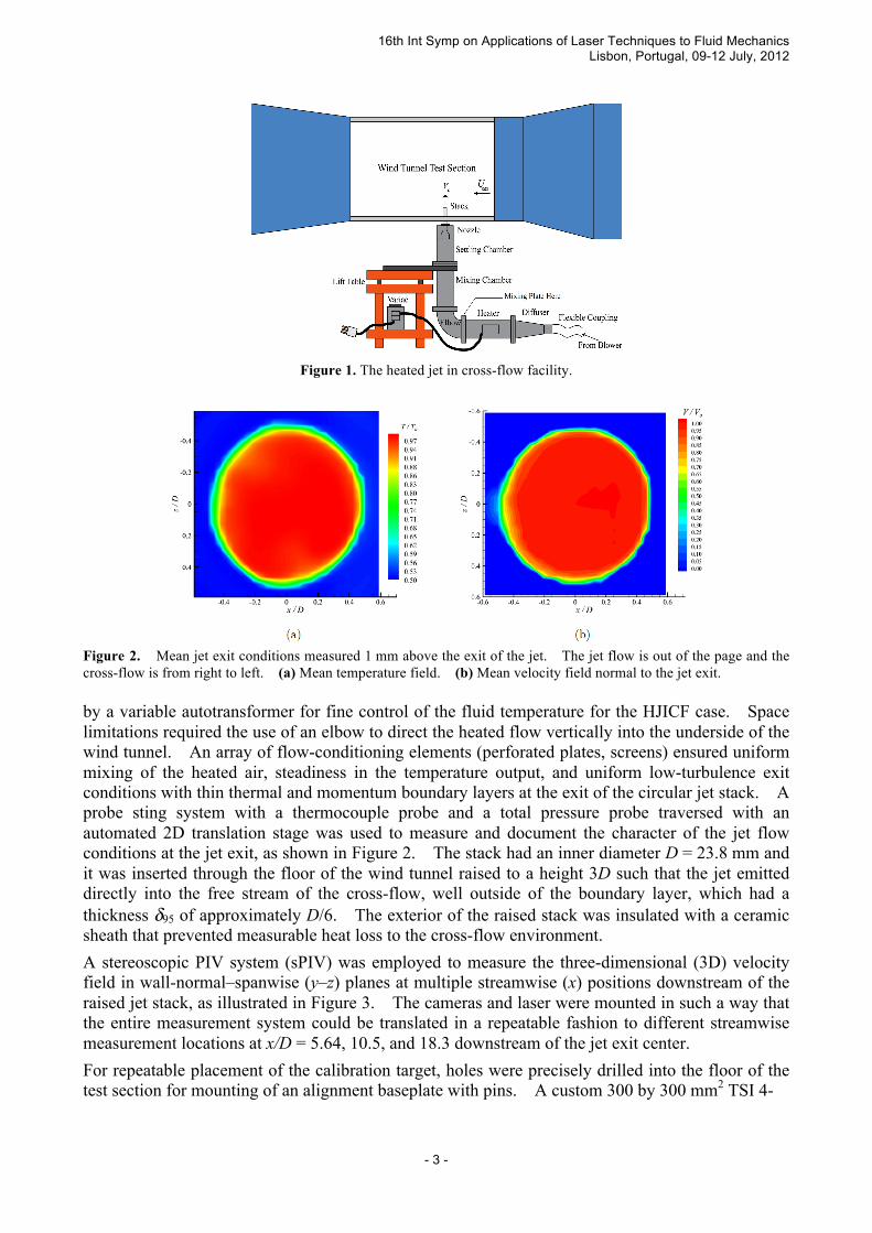
Figure 1. The heated jet in cross-flow facility.
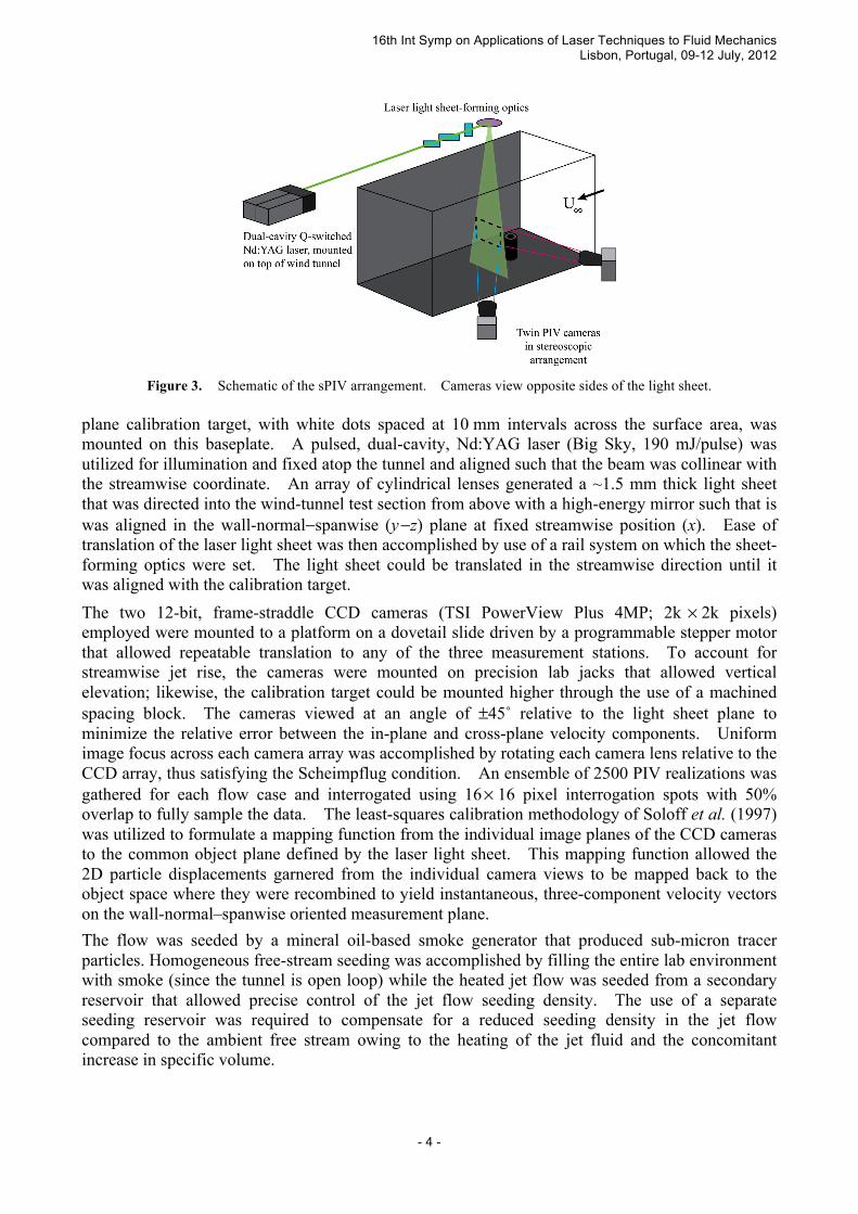
Figure 2. Mean jet exit conditions measured 1 mm above the exit of the jet. The jet flow is out of the page and the cross-flow is from right to left. (a) Mean temperature field. (b) Mean velocity field normal to the jet exit. by a variable autotransformer for fine control of the fluid temperature for the HJICF case. Space limitations required the use of an elbow to direct the heated flow vertically into the underside of the wind tunnel. An array of flow-conditioning elements (perforated plates, screens) ensured uniform mixing of the heated air, steadiness in the temperature output, and uniform low-turbulence exit conditions with thin thermal and momentum boundary layers at the exit of the circular jet stack. A probe sting system with a thermocouple probe and a total pressure probe traversed with an automated 2D translation stage was used to measure and document the character of the jet flow conditions at the jet exit, as shown in Figure 2. The stack had an inner diameter D = 23.8 mm and it was inserted through the floor of the wind tunnel raised to a height 3D such that the jet emitted directly into the free stream of the cross-flow, well outside of the boundary layer, which had a thickness δ95 of approximately D/6. The exterior of the raised stack was insulated with a ceramic sheath that prevented measurable heat loss to the cross-flow environment.
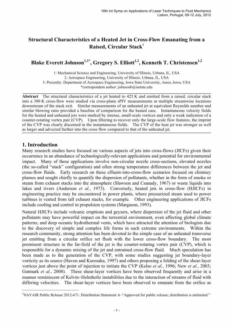
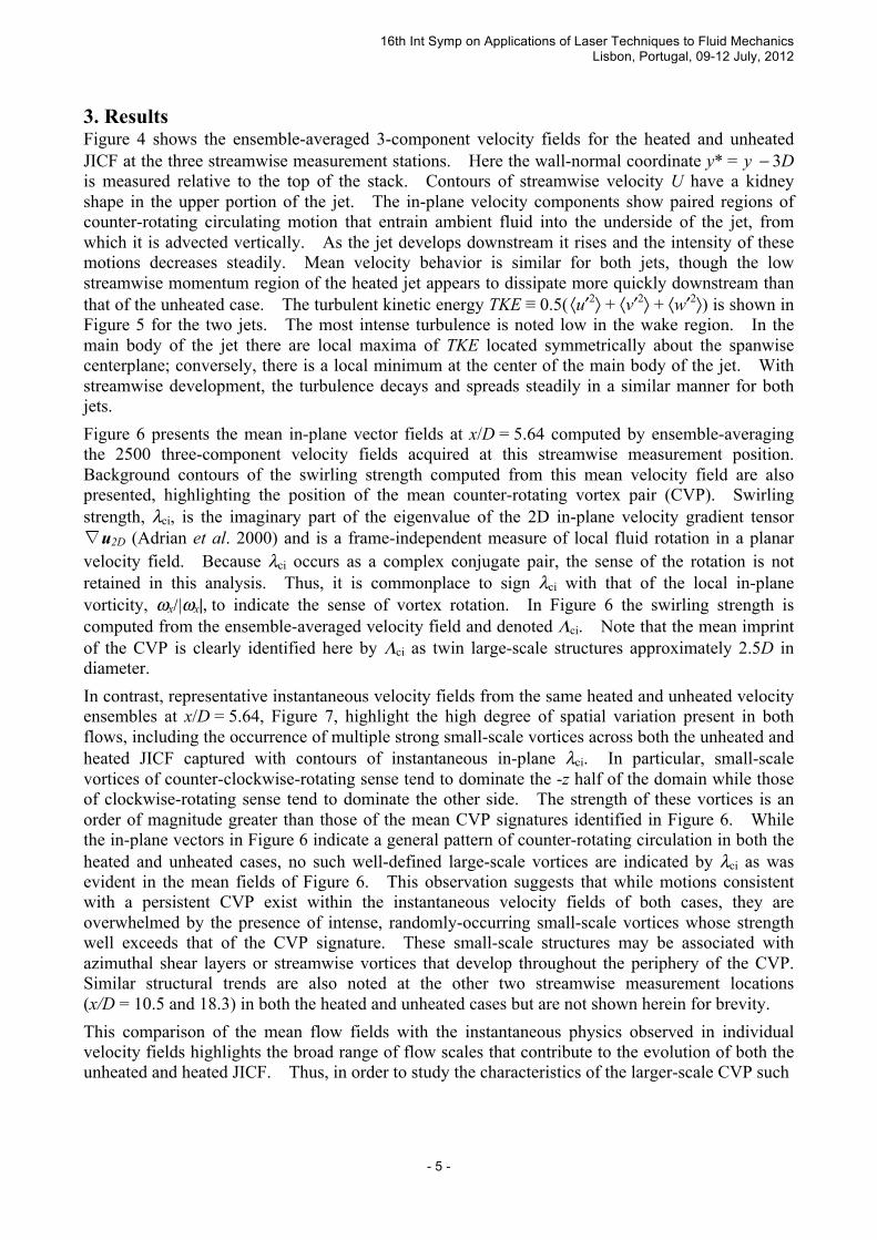
A stereoscopic PIV system (sPIV) was employed to measure the three-dimensional (3D) velocity field in wall-normal–spanwise (y–z) planes at multiple streamwise (x) positions downstream of the raised jet stack, as illustrated in Figure 3. The cameras and laser were mounted in such a way that the entire measurement system could be translated in a repeatable fashion to different streamwise measurement locations at x/D = 5.64, 10.5, and 18.3 downstream of the jet exit center.
For repeatable placement of the calibration target, holes were precisely drilled into the floor of the test section for mounting of an alignment baseplate with pins. A custom 300 by 300 mm2 TSI 4-
16th Int Symp on Applications of Laser Techniques to Fluid Mechanics Lisbon, Portugal, 09-12 July, 2012
- 4 -
Figure 3. Schematic of the sPIV arrangement. Cameras view opposite sides of the light sheet.
plane calibration target, with white dots spaced at 10 mm intervals across the surface area, was mounted on this baseplate. A pulsed, dual-cavity, Nd:YAG laser (Big Sky, 190 mJ/pulse) was utilized for illumination and fixed atop the tunnel and aligned such that the beam was collinear with the streamwise coordinate. An array of cylindrical lenses generated a ~1.5 mm thick light sheet that was directed into the wind-tunnel test section from above with a high-energy mirror such that is was aligned in the wall-normal−spanwise (y −z) plane at fixed streamwise position (x). Ease of translation of the laser light sheet was then accomplished by use of a rail system on which the sheet-forming optics were set. The light sheet could be translated in the streamwise direction until it was aligned with the calibration target.
The two 12-bit, frame-straddle CCD cameras (TSI PowerView Plus 4MP; 2k × 2k pixels) employed were mounted to a platform on a dovetail slide driven by a programmable stepper motor that allowed repeatable translation to any of the three measurement stations. To account for streamwise jet rise, the cameras were mounted on precision lab jacks that allowed vertical elevation; likewise, the calibration target could be mounted higher through the use of a machined spacing block. The cameras viewed at an angle of ±45˚ relative to the light sheet plane to minimize the relative error between the in-plane and cross-plane velocity components. Uniform image focus across each camera array was accomplished by rotating each camera lens relative to the CCD array, thus satisfying the Scheimpflug condition. An ensemble of 2500 PIV realizations was gathered for each flow case and interrogated using 16 × 16 pixel interrogation spots with 50% overlap to fully sample the data. The least-squares calibration methodology of Soloff et al. (1997) was utilized to formulate a mapping function from the individual image planes of the CCD cameras to the common object plane defined by the laser light sheet. This mapping function allowed the 2D particle displacements garnered from the individual camera views to be mapped back to the object space where they were recombined to yield instantaneous, three-component velocity vectors on the wall-normal–spanwise oriented measurement plane.
The flow was seeded by a mineral oil-based smoke generator that produced sub-micron tracer particles. Homogeneous free-stream seeding was accomplished by filling the entire lab environment with smoke (since the tunnel is open loop) while the heated jet flow was seeded from a secondary reservoir that allowed precise control of the jet flow seeding density. The use of a separate seeding reservoir was required to compensate for a reduced seeding density in the jet flow compared to the ambient free stream owing to the heating of the jet fluid and the concomitant increase in specific volume.
16th Int Symp on Applications of Laser Techniques to Fluid Mechanics Lisbon, Portugal, 09-12 July, 2012
- 5 -
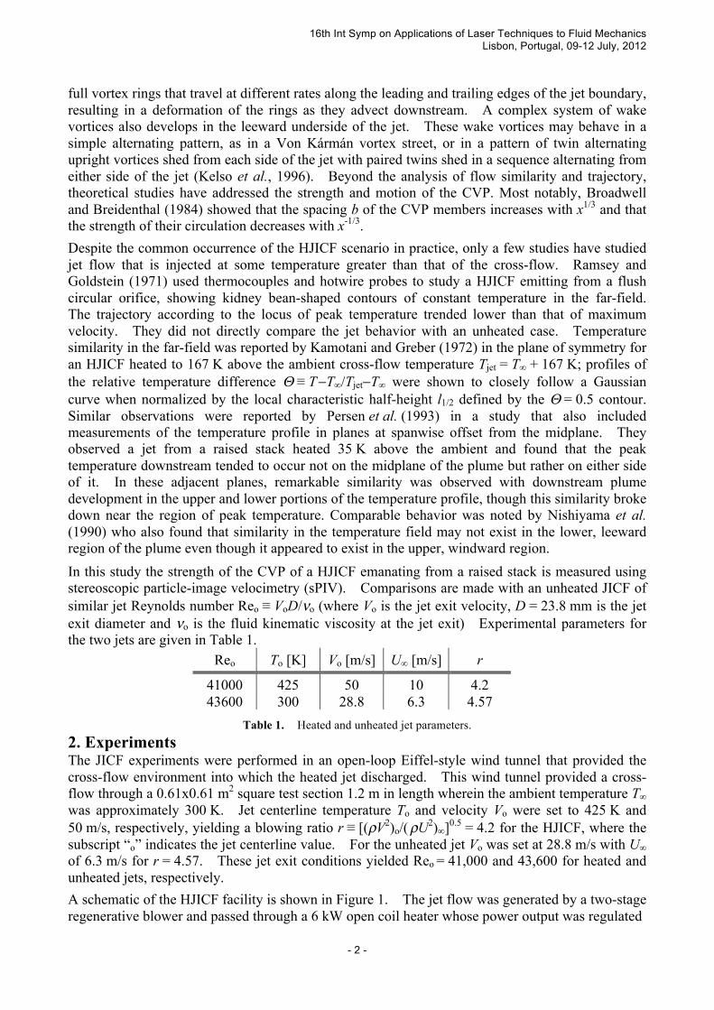
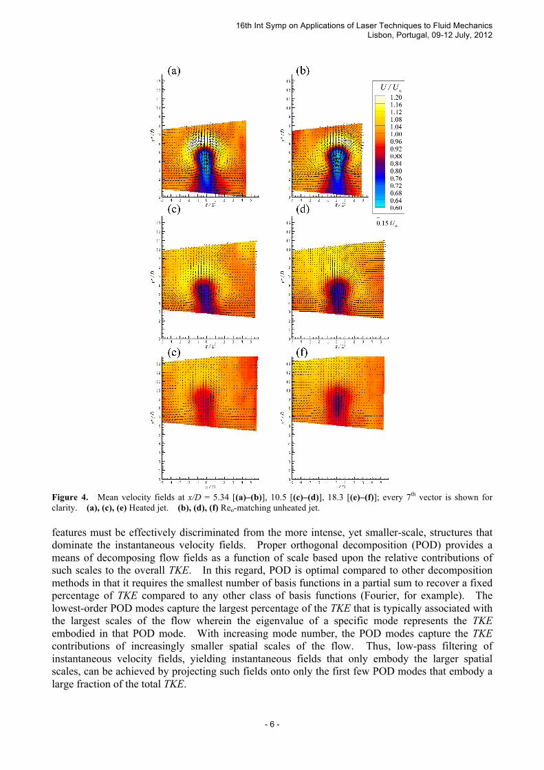
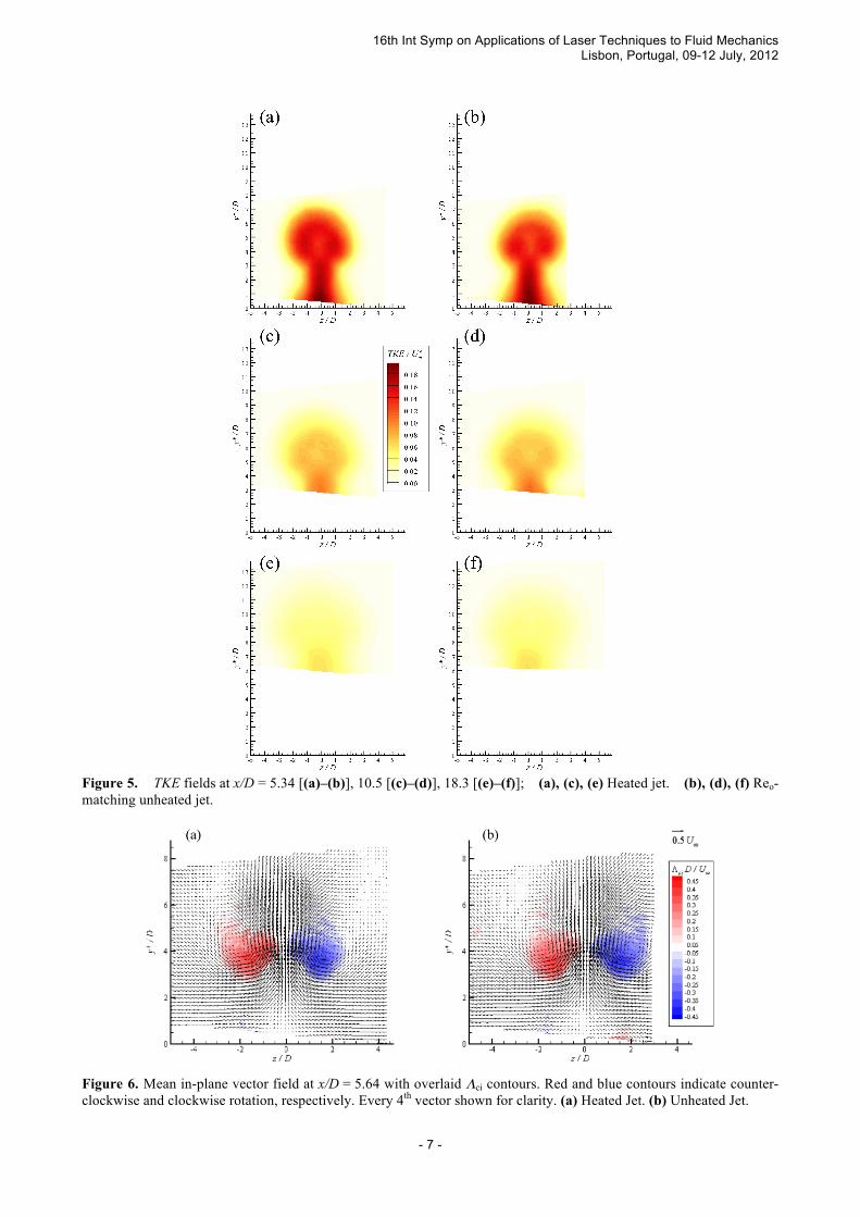
3. Results Figure 4 shows the ensemble-averaged 3-component velocity fields for the heated and unheated JICF at the three streamwise measurement stations. Here the wall-normal coordinate y* = y − 3D is measured relative to the top of the stack. Contours of streamwise velocity U have a kidney shape in the upper portion of the jet. The in-plane velocity components show paired regions of counter-rotating circulating motion that entrain ambient fluid into the underside of the jet, from which it is advected vertically. As the jet develops downstream it rises and the intensity of these motions decreases steadily. Mean velocity behavior is similar for both jets, though the low streamwise momentum region of the heated jet appears to dissipate more quickly downstream than that of the unheated case. The turbulent kinetic energy TKE ≡ 0.5( 〈u′2〉 + 〈v′2〉 + 〈w′2〉) is shown in Figure 5 for the two jets. The most intense turbulence is noted low in the wake region. In the main body of the jet there are local maxima of TKE located symmetrically about the spanwise centerplane; conversely, there is a local minimum at the center of the main body of the jet. With streamwise development, the turbulence decays and spreads steadily in a similar manner for both jets.
Figure 6 presents the mean in-plane vector fields at x/D = 5.64 computed by ensemble-averaging the 2500 three-component velocity fields acquired at this streamwise measurement position. Background contours of the swirling strength computed from this mean velocity field are also presented, highlighting the position of the mean counter-rotating vortex pair (CVP). Swirling strength, λci, is the imaginary part of the eigenvalue of the 2D in-plane velocity gradient tensor ∇u2D (Adrian et al. 2000) and is a frame-independent measure of local fluid rotation in a planar velocity field. Because λci occurs as a complex conjugate pair, the sense of the rotation is not retained in this analysis. Thus, it is commonplace to sign λci with that of the local in-plane vorticity, ωx/|ωx|, to indicate the sense of vortex rotation. In Figure 6 the swirling strength is computed from the ensemble-averaged velocity field and denoted Λci. Note that the mean imprint of the CVP is clearly identified here by Λci as twin large-scale structures approximately 2.5D in diameter.
In contrast, representative instantaneous velocity fields from the same heated and unheated velocity ensembles at x/D = 5.64, Figure 7, highlight the high degree of spatial variation present in both flows, including the occurrence of multiple strong small-scale vortices across both the unheated and heated JICF captured with contours of instantaneous in-plane λci. In particular, small-scale vortices of counter-clockwise-rotating sense tend to dominate the -z half of the domain while those of clockwise-rotating sense tend to dominate the other side. The strength of these vortices is an order of magnitude greater than those of the mean CVP signatures identified in Figure 6. While the in-plane vectors in Figure 6 indicate a general pattern of counter-rotating circulation in both the heated and unheated cases, no such well-defined large-scale vortices are indicated by λci as was evident in the mean fields of Figure 6. This observation suggests that while motions consistent with a persistent CVP exist within the instantaneous velocity fields of both cases, they are overwhelmed by the presence of intense, randomly-occurring small-scale vortices whose strength well exceeds that of the CVP signature. These small-scale structures may be associated with azimuthal shear layers or streamwise vortices that develop throughout the periphery of the CVP. Similar structural trends are also noted at the other two streamwise measurement locations (x/D = 10.5 and 18.3) in both the heated and unheated cases but are not shown herein for brevity.
This comparison of the mean flow fields with the instantaneous physics observed in individual velocity fields highlights the broad range of flow scales that contribute to the evolution of both the unheated and heated JICF. Thus, in order to study the characteristics of the larger-scale CVP such
16th Int Symp on Applications of Laser Techniques to Fluid Mechanics Lisbon, Portugal, 09-12 July, 2012
- 6 -
Figure 4. Mean velocity fields at x/D = 5.34 [(a)–(b)], 10.5 [(c)–(d)], 18.3 [(e)–(f)]; every 7th vector is shown for clarity. (a), (c), (e) Heated jet. (b), (d), (f) Reo-matching unheated jet. features must be effectively discriminated from the more intense, yet smaller-scale, structures that dominate the instantaneous velocity fields. Proper orthogonal decomposition (POD) provides a means of decomposing flow fields as a function of scale based upon the relative contributions of such scales to the overall TKE. In this regard, POD is optimal compared to other decomposition methods in that it requires the smallest number of basis functions in a partial sum to recover a fixed percentage of TKE compared to any other class of basis functions (Fourier, for example). The lowest-order POD modes capture the largest percentage of the TKE that is typically associated with the largest scales of the flow wherein the eigenvalue of a specific mode represents the TKE embodied in that POD mode. With increasing mode number, the POD modes capture the TKE contributions of increasingly smaller spatial scales of the flow. Thus, low-pass filtering of instantaneous velocity fields, yielding instantaneous fields that only embody the larger spatial scales, can be achieved by projecting such fields onto only the first few POD modes that embody a large fraction of the total TKE.
16th Int Symp on Applications of Laser Techniques to Fluid Mechanics Lisbon, Portugal, 09-12 July, 2012
- 7 -
Figure 5. TKE fields at x/D = 5.34 [(a)–(b)], 10.5 [(c)–(d)], 18.3 [(e)–(f)]; (a), (c), (e) Heated jet. (b), (d), (f) Reo-matching unheated jet.
Figure 6. Mean in-plane vector field at x/D = 5.64 with overlaid Λci contours. Red and blue contours indicate counter-clockwise and clockwise rotation, respectively. Every 4th vector shown for clarity. (a) Heated Jet. (b) Unheated Jet.
16th Int Symp on Applications of Laser Techniques to Fluid Mechanics Lisbon, Portugal, 09-12 July, 2012
- 8 -
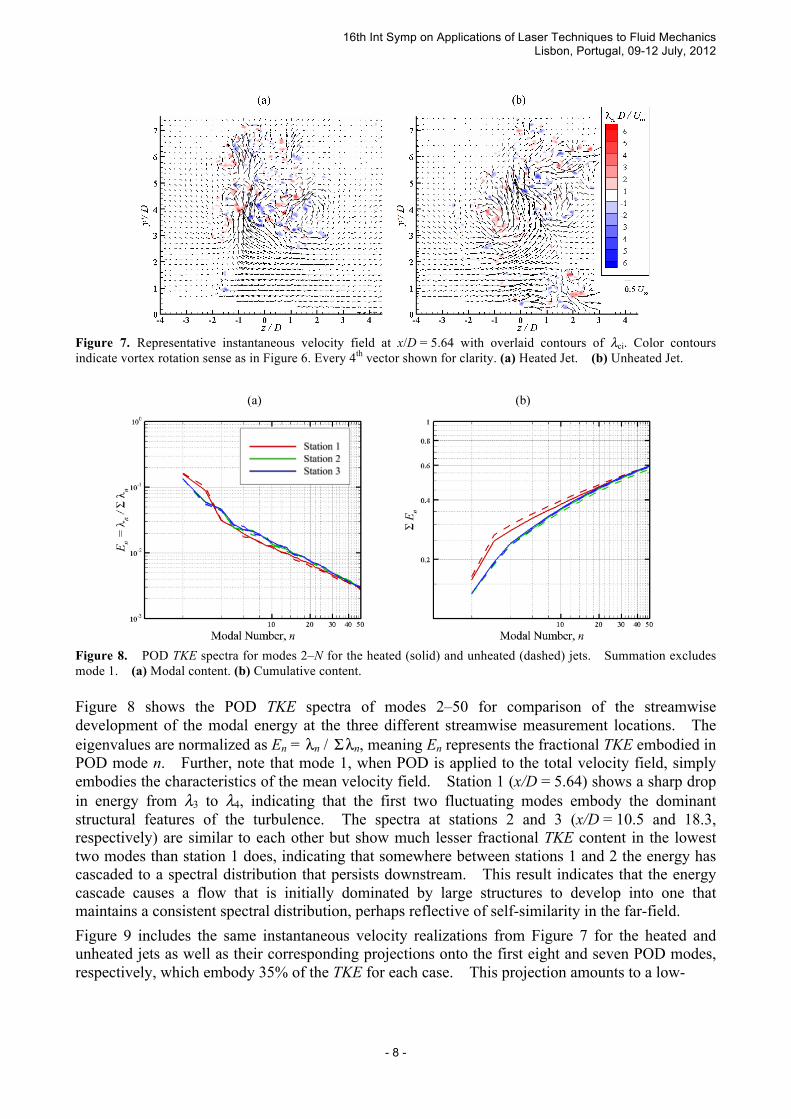
Figure 7. Representative instantaneous velocity field at x/D = 5.64 with overlaid contours of λci. Color contours indicate vortex rotation sense as in Figure 6. Every 4th vector shown for clarity. (a) Heated Jet. (b) Unheated Jet.
Figure 8. POD TKE spectra for modes 2–N for the heated (solid) and unheated (dashed) jets. Summation excludes mode 1. (a) Modal content. (b) Cumulative content. Figure 8 shows the POD TKE spectra of modes 2–50 for comparison of the streamwise development of the modal energy at the three different streamwise measurement locations. The eigenvalues are normalized as En = λn / Σ λn, meaning En represents the fractional TKE embodied in POD mode n. Further, note that mode 1, when POD is applied to the total velocity field, simply embodies the characteristics of the mean velocity field. Station 1 (x/D = 5.64) shows a sharp drop in energy from λ3 to λ4, indicating that the first two fluctuating modes embody the dominant structural features of the turbulence. The spectra at stations 2 and 3 (x/D = 10.5 and 18.3, respectively) are similar to each other but show much lesser fractional TKE content in the lowest two modes than station 1 does, indicating that somewhere between stations 1 and 2 the energy has cascaded to a spectral distribution that persists downstream. This result indicates that the energy cascade causes a flow that is initially dominated by large structures to develop into one that maintains a consistent spectral distribution, perhaps reflective of self-similarity in the far-field.
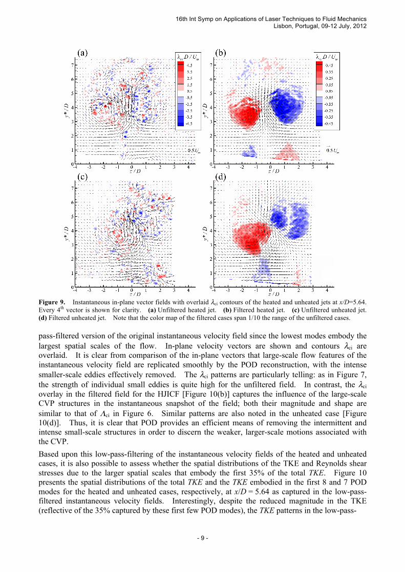
Figure 9 includes the same instantaneous velocity realizations from Figure 7 for the heated and unheated jets as well as their corresponding projections onto the first eight and seven POD modes, respectively, which embody 35% of the TKE for each case. This projection amounts to a low-
16th Int Symp on Applications of Laser Techniques to Fluid Mechanics Lisbon, Portugal, 09-12 July, 2012
- 9 -
Figure 9. Instantaneous in-plane vector fields with overlaid λci contours of the heated and unheated jets at x/D=5.64. Every 4th vector is shown for clarity. (a) Unfiltered heated jet. (b) Filtered heated jet. (c) Unfiltered unheated jet. (d) Filtered unheated jet. Note that the color map of the filtered cases span 1/10 the range of the unfiltered cases. pass-filtered version of the original instantaneous velocity field since the lowest modes embody the largest spatial scales of the flow. In-plane velocity vectors are shown and contours λci are overlaid. It is clear from comparison of the in-plane vectors that large-scale flow features of the instantaneous velocity field are replicated smoothly by the POD reconstruction, with the intense smaller-scale eddies effectively removed. The λci patterns are particularly telling: as in Figure 7, the strength of individual small eddies is quite high for the unfiltered field. In contrast, the λci overlay in the filtered field for the HJICF [Figure 10(b)] captures the influence of the large-scale CVP structures in the instantaneous snapshot of the field; both their magnitude and shape are similar to that of Λci in Figure 6. Similar patterns are also noted in the unheated case [Figure 10(d)]. Thus, it is clear that POD provides an efficient means of removing the intermittent and intense small-scale structures in order to discern the weaker, larger-scale motions associated with the CVP.
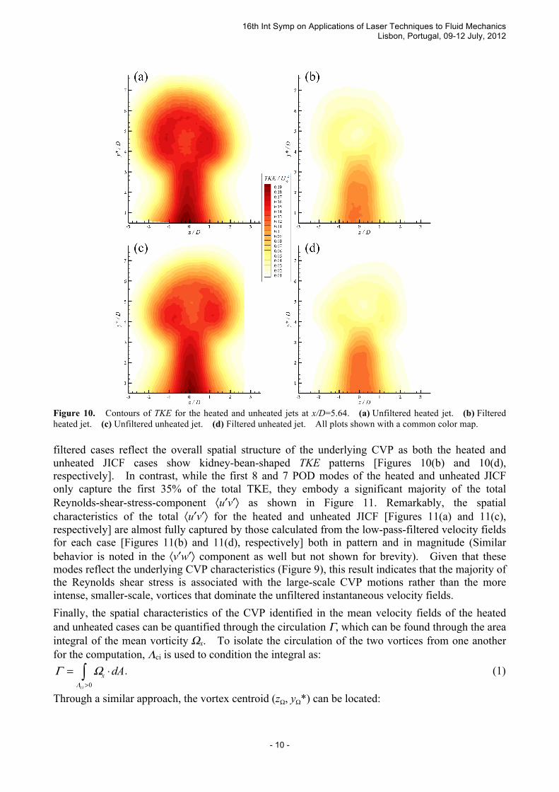
Based upon this low-pass-filtering of the instantaneous velocity fields of the heated and unheated cases, it is also possible to assess whether the spatial distributions of the TKE and Reynolds shear stresses due to the larger spatial scales that embody the first 35% of the total TKE. Figure 10 presents the spatial distributions of the total TKE and the TKE embodied in the first 8 and 7 POD modes for the heated and unheated cases, respectively, at x/D = 5.64 as captured in the low-pass-filtered instantaneous velocity fields. Interestingly, despite the reduced magnitude in the TKE (reflective of the 35% captured by these first few POD modes), the TKE patterns in the low-pass-
16th Int Symp on Applications of Laser Techniques to Fluid Mechanics Lisbon, Portugal, 09-12 July, 2012
- 10 -
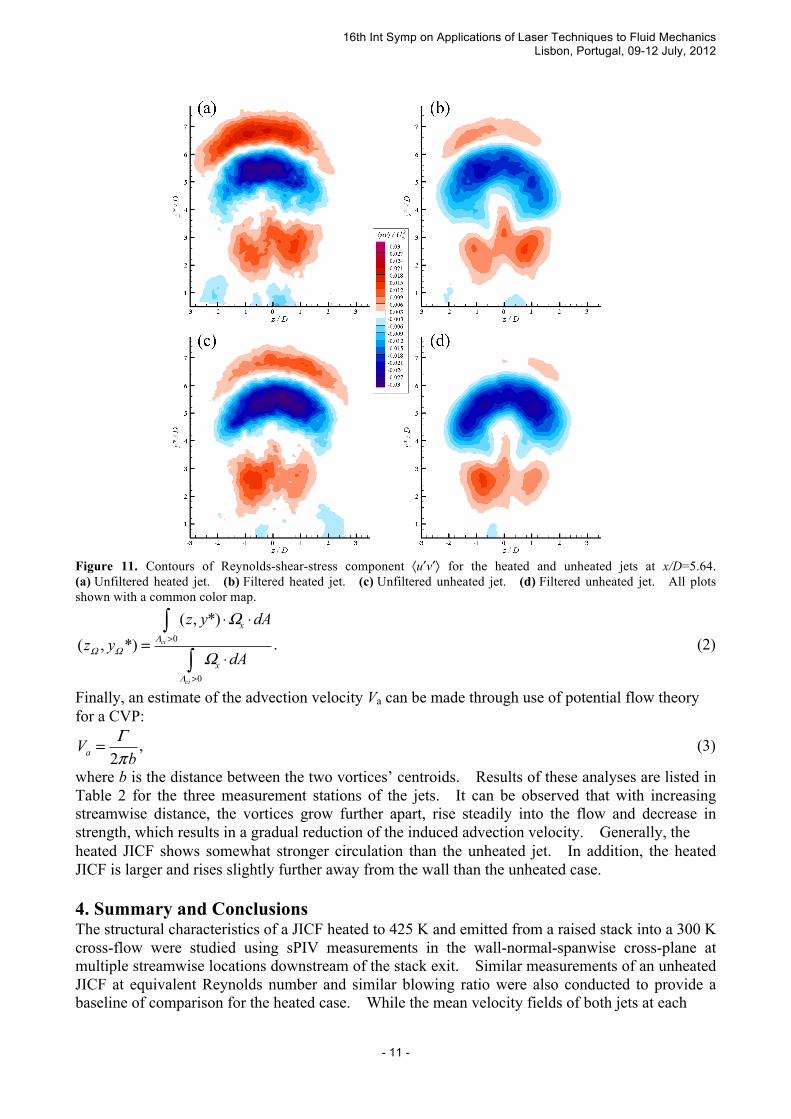
Figure 10. Contours of TKE for the heated and unheated jets at x/D=5.64. (a) Unfiltered heated jet. (b) Filtered heated jet. (c) Unfiltered unheated jet. (d) Filtered unheated jet. All plots shown with a common color map. filtered cases reflect the overall spatial structure of the underlying CVP as both the heated and unheated JICF cases show kidney-bean-shaped TKE patterns [Figures 10(b) and 10(d), respectively]. In contrast, while the first 8 and 7 POD modes of the heated and unheated JICF only capture the first 35% of the total TKE, they embody a significant majority of the total Reynolds-shear-stress-component 〈u′v′〉 as shown in Figure 11. Remarkably, the spatial characteristics of the total 〈u′v′〉 for the heated and unheated JICF [Figures 11(a) and 11(c), respectively] are almost fully captured by those calculated from the low-pass-filtered velocity fields for each case [Figures 11(b) and 11(d), respectively] both in pattern and in magnitude (Similar behavior is noted in the 〈v′w′〉 component as well but not shown for brevity). Given that these modes reflect the underlying CVP characteristics (Figure 9), this result indicates that the majority of the Reynolds shear stress is associated with the large-scale CVP motions rather than the more intense, smaller-scale, vortices that dominate the unfiltered instantaneous velocity fields.
Finally, the spatial characteristics of the CVP identified in the mean velocity fields of the heated and unheated cases can be quantified through the circulation Γ, which can be found through the area integral of the mean vorticity Ωx. To isolate the circulation of the two vortices from one another for the computation, Λci is used to condition the integral as:
0ci
x dAΛ
Γ Ω>
= ⋅∫ . (1)
Through a similar approach, the vortex centroid (zΩ, yΩ*) can be located:
16th Int Symp on Applications of Laser Techniques to Fluid Mechanics Lisbon, Portugal, 09-12 July, 2012
- 11 -
Figure 11. Contours of Reynolds-shear-stress component 〈u′v′〉 for the heated and unheated jets at x/D=5.64. (a) Unfiltered heated jet. (b) Filtered heated jet. (c) Unfiltered unheated jet. (d) Filtered unheated jet. All plots shown with a common color map.
0
0
( , *)( , *) ci
ci
x
x
z y dAz y
dAΛ
Ω Ω
Λ
Ω
Ω>
>
⋅ ⋅=
⋅
∫
∫. (2)
Finally, an estimate of the advection velocity Va can be made through use of potential flow theory for a CVP:
2aV bΓπ
= , (3)
where b is the distance between the two vortices’ centroids. Results of these analyses are listed in Table 2 for the three measurement stations of the jets. It can be observed that with increasing streamwise distance, the vortices grow further apart, rise steadily into the flow and decrease in strength, which results in a gradual reduction of the induced advection velocity. Generally, the heated JICF shows somewhat stronger circulation than the unheated jet. In addition, the heated JICF is larger and rises slightly further away from the wall than the unheated case. 4. Summary and Conclusions The structural characteristics of a JICF heated to 425 K and emitted from a raised stack into a 300 K cross-flow were studied using sPIV measurements in the wall-normal-spanwise cross-plane at multiple streamwise locations downstream of the stack exit. Similar measurements of an unheated JICF at equivalent Reynolds number and similar blowing ratio were also conducted to provide a baseline of comparison for the heated case. While the mean velocity fields of both jets at each
16th Int Symp on Applications of Laser Techniques to Fluid Mechanics Lisbon, Portugal, 09-12 July, 2012
- 12 -
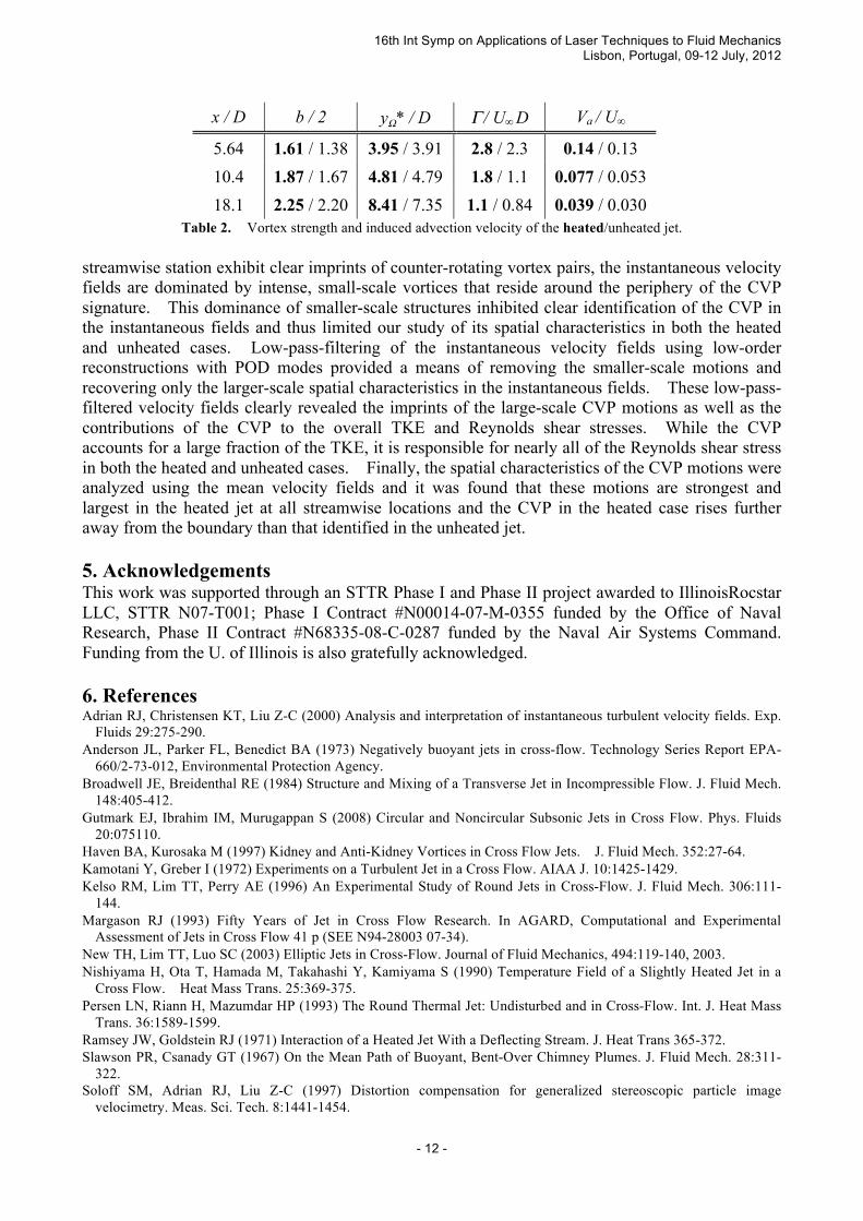
x / D b / 2 yΩ* / D Γ / U∞ D Va / U∞
5.64 1.61 / 1.38 3.95 / 3.91 2.8 / 2.3 0.14 / 0.13 10.4 1.87 / 1.67 4.81 / 4.79 1.8 / 1.1 0.077 / 0.053 18.1 2.25 / 2.20 8.41 / 7.35 1.1 / 0.84 0.039 / 0.030
Table 2. Vortex strength and induced advection velocity of the heated/unheated jet. streamwise station exhibit clear imprints of counter-rotating vortex pairs, the instantaneous velocity fields are dominated by intense, small-scale vortices that reside around the periphery of the CVP signature. This dominance of smaller-scale structures inhibited clear identification of the CVP in the instantaneous fields and thus limited our study of its spatial characteristics in both the heated and unheated cases. Low-pass-filtering of the instantaneous velocity fields using low-order reconstructions with POD modes provided a means of removing the smaller-scale motions and recovering only the larger-scale spatial characteristics in the instantaneous fields. These low-pass-filtered velocity fields clearly revealed the imprints of the large-scale CVP motions as well as the contributions of the CVP to the overall TKE and Reynolds shear stresses. While the CVP accounts for a large fraction of the TKE, it is responsible for nearly all of the Reynolds shear stress in both the heated and unheated cases. Finally, the spatial characteristics of the CVP motions were analyzed using the mean velocity fields and it was found that these motions are strongest and largest in the heated jet at all streamwise locations and the CVP in the heated case rises further away from the boundary than that identified in the unheated jet. 5. Acknowledgements This work was supported through an STTR Phase I and Phase II project awarded to IllinoisRocstar LLC, STTR N07-T001; Phase I Contract #N00014-07-M-0355 funded by the Office of Naval Research, Phase II Contract #N68335-08-C-0287 funded by the Naval Air Systems Command. Funding from the U. of Illinois is also gratefully acknowledged. 6. References Adrian RJ, Christensen KT, Liu Z-C (2000) Analysis and interpretation of instantaneous turbulent velocity fields. Exp.
Fluids 29:275-290. Anderson JL, Parker FL, Benedict BA (1973) Negatively buoyant jets in cross-flow. Technology Series Report EPA-
660/2-73-012, Environmental Protection Agency. Broadwell JE, Breidenthal RE (1984) Structure and Mixing of a Transverse Jet in Incompressible Flow. J. Fluid Mech.
148:405-412. Gutmark EJ, Ibrahim IM, Murugappan S (2008) Circular and Noncircular Subsonic Jets in Cross Flow. Phys. Fluids
20:075110. Haven BA, Kurosaka M (1997) Kidney and Anti-Kidney Vortices in Cross Flow Jets. J. Fluid Mech. 352:27-64. Kamotani Y, Greber I (1972) Experiments on a Turbulent Jet in a Cross Flow. AIAA J. 10:1425-1429. Kelso RM, Lim TT, Perry AE (1996) An Experimental Study of Round Jets in Cross-Flow. J. Fluid Mech. 306:111-
144. Margason RJ (1993) Fifty Years of Jet in Cross Flow Research. In AGARD, Computational and Experimental
Assessment of Jets in Cross Flow 41 p (SEE N94-28003 07-34). New TH, Lim TT, Luo SC (2003) Elliptic Jets in Cross-Flow. Journal of Fluid Mechanics, 494:119-140, 2003. Nishiyama H, Ota T, Hamada M, Takahashi Y, Kamiyama S (1990) Temperature Field of a Slightly Heated Jet in a
Cross Flow. Heat Mass Trans. 25:369-375. Persen LN, Riann H, Mazumdar HP (1993) The Round Thermal Jet: Undisturbed and in Cross-Flow. Int. J. Heat Mass
Trans. 36:1589-1599. Ramsey JW, Goldstein RJ (1971) Interaction of a Heated Jet With a Deflecting Stream. J. Heat Trans 365-372. Slawson PR, Csanady GT (1967) On the Mean Path of Buoyant, Bent-Over Chimney Plumes. J. Fluid Mech. 28:311-
322. Soloff SM, Adrian RJ, Liu Z-C (1997) Distortion compensation for generalized stereoscopic particle image
velocimetry. Meas. Sci. Tech. 8:1441-1454.