Embed Size (px)
Citation preview
STRUCTURAL BIREFRINGENCE IN AMORPHOUSSOLIDS
B SIR C. V. RAMAN(From the Raman Research Institute, Bangalore)
Received April 18, 1950
1. INTRODUCTION
THE birefringence exhibited by optically isotropic solids when deformed bystress is familiar knowledge and forms the theme of the subject of photo-elasticity. There exists, however, a second kind of birefringence which mayalso be exhibited by amorphous solids and which differs both in its originsand in its observable characters from the photo-elastic effect. To distinguishit from the latter phenomenon, it has been designated as structural birefrin-gence (Raman, 1950). The name is intended to convey the idea that suchbirefringence owes its origin to anisotropy of structure existing even whenthe material is free from stress. Such anisotropy is, of course, not a normalproperty of the material as in the case of crystals, but is "accidental" in thesense that it is a consequence of special circumstances existing during theformation of the solid. The recognition of such birefringence as a distinctphenomenon is compelled by a study of the facts observed with vitreoussilica and described in the paper cited. Structural birefringence in the caseof this substance manifests itself as streaks or sheets of luminosity—inex-plicable on the basis of photo-elastic theory—which are clearly the result offlow in the material while in a plastic state before its final solidification.
The present paper describes similar studies made with other materialsand especially with the inorganic glasses. The results show unequivocallythat structural birefringence is also exhibited by such glasses, either by itselfor in conjunction with the photo-elastic effect. As is well known, the pro-cess known as " annealing " is an essential part of the technique of glassmanufacture. Its purpose is to remove the internal stresses set up in thefabricated material by differential rates of cooling of its parts, and the testapplied to determine whether this has been accomplished is the disappear-ance of birefringence. Except, however, in the case of high-grade opticalglass where special techniques are employed to obtain a perfectly homo-geneous and isotropic product, the process of annealing never actually succeeds
Al 207
208 C. V. Raman
in removing all observable birefringence. Indeed, the commoner commercialvarieties of glass exhibit, when critically examined, an easily noticeablebirefringence. It is with this phenomenon that we are concerned in thepresent paper.
As already noted in the paper on vitreous silica, the detection and studyof a feeble birefringence needs the use of a light source of adequate intensity.The most satisfactory method is to place the object under examination betweentwo crossed polaroid sheets, and send a beam of sunlight through it. Forobservation or photography of a large area of the object at one time, it willbe necessary to diffuse the incident light beam by a sheet of ground glass.As polaroid sheets are available up to twelve inches square in area, quitelarge objects can be examined in this way. It is necessary that the surfacesof the object through which the light enters and emerges are flat andparallel. This requirement may be avoided by immersing the object in aflat-sided cell containing a liquid of suitable refractive index. But thisnaturally restricts the size of the objects which can be examined.
2. THE BIREFRINGENCE OF PLATE GLASS
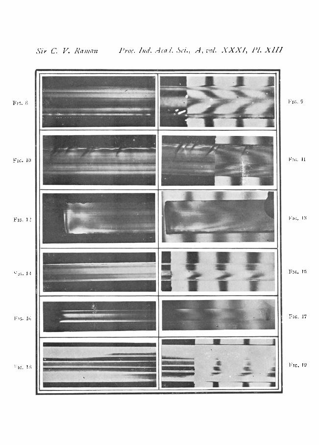
Common glass is produced commercially on a large scale in the formof sheets or plates of any desired thickness. The process of the manu-facture and the annealing of the product are both so highly perfected thata sheet of quarter-inch plate glass when held normally between crossedpolaroids usually shows no noticeable restoration of light. One might betempted to infer from such an observation that the material is opticallyisotropic. Actually however, this is not the case, as becomes apparent whenthe plate is set and viewed edgewise between crossed polaroids, the lighttraversing the material in a direction parallel to its surfaces. A strongrestoration of light is then noticed; this is a maximum when the plate isinclined at an angle of 45° to the principal planes of the polariser andanalyser but, as is to be expected, vanishes when the plate is set parallel toeither of these planes. The origin of the birefringence becomes evidentwhen the edge of the plate is viewed through a magnifying lens in the circum-stances stated. It is then seen that the entire thickness is made up of a greatmany laminar parallel to the surfaces of the plate overlying each other (seePlate XIII). To see the laminae clearly, it is necessary that they should beviewed in a direction accurately parallel to the surfaces of the plate; further,as already remarked, the edges through which the light enters and emergesshould be flat and parallel. (Alternatively, the observations may be madewith the plate immersed in a flat-sided cell containing xylene). The factthat the individual lamine are birefringent and in varying degrees is evident
Siruclural Birefringence in Amorphous Solids 209
from the varying intensity of the restoration of light that they produce. Thesame may also be very elegantly exhibited by superimposing a quartz wedge onthe edge of the plate; the straight fringes due to the wedge run at right anglesto the plate and appear above and below it, while the fringes due to thecombination of the wedge and the plate appear in the central strip. Thecourse of the latter fringes then displays the birefringence of the individuallamin,T very clearly (see Plate XIII).
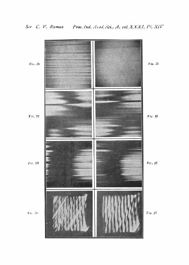
The foregoing descriptions refer to the phenomena exhibited by a stripof plate glass at a sufficient distance from its free edges. At and near thesefree edges, however, we observe a restoration of light which is a distinctphenomenon, as is shown by its being most conspicuous when the strip isheld in such a position (parallel to the principal plane of either the polariseror the analyser) in which the structural birefringence vanishes; it is evidentlya photo-elastic birefringence produced by the stresses set up in the vicinityof the edges of the strip when it is cut. If the strip be inclined so as to restorethe visibility of the structural birefringence, we notice a superposition of thetwo effects in the vicinity of the edges. Such superposition and the specialfeatures arising from it are particularly conspicuous when the plate underobservation is thick, and its length is also not much greater than its thickness.A characteristic effect noticed is that a lamina which appears as a brightstreak on one side of the plate changes over to a dark streak on the otherside as it crosses a dark band of the photo-elastic pattern, and vice versa.Several examples of this effect are to be seen in the figures reproduced inPlate XIV.
It should be mentioned here that if the edges of a thick plate of glassare smoothed and polished, its laminated structure may be observed evenwithout the aid of polarised light, by merely viewing the plate in a directionaccurately parallel to its surfaces. The individual lamine are then clearlyvisible, but they disappear if the plate be slightly tilted. If a narrow illumi-nated slit is observed through the edge of the plate, the laminated structuredives rise to various interesting optical effects ascribable to reflection anddiffraction. These vary rapidly when the direction of the light rays traversingthe plate is altered with reference to the plane of the laminations. To de-scribe or discuss these effects in any detail would take us far beyond the scopeof the present paper.
It seems fairly obvious that the laminated anisotropic structure of plateglass revealed by its optical behaviour is a consequence of the processemployed in its manufacture. The molten glass emerges from the containerin the furnace and passes between the forming rollers while it is still in a
210 C. V. Raman
plastic condition and becomes a sheet which moves on continuously untilit finally sets and becomes solid. It is scarcely to be supposed that a sheetof glass formed under these dynamic conditions would possess the isotropicstructure which is the ideal state of an amorphous solid. It appears muchmore probable that the movement of the layers of the material with respectto each other would result in the final product having a laminated structure,as is actually observed. The thickness of the lamine would presumablybe determined by the plasticity of the material and the speed of its passagethrough the rollers, as well as by their distance apart.
3. THE BIREFRINGENCE OF MOULDED GLASS
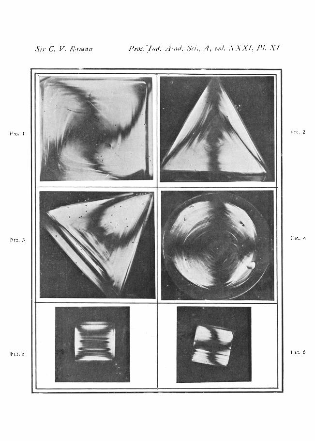
The process employed for the mass production of objects of glass havinga desired form is to use moulds. The glass is poured into the mould whilein the fluid state and removed from it when it has solidified. Examinationin polarised light of glass formed in this manner shows that the birefringencepattern which it exhibits bears a readily recognisable relationship to thegeometric shape of the object. For instance, a circular disk of glass whenviewed normally between crossed polaroids shows a dark cross which remainsfixed when the disk is rotated in its own plane, the arms of the cross lying inthe principal planes of the polariser and the analyser; the disk also exhibitsa strong birefringence when held at an angle of 45° to these planes andviewed edgewise. A cube of moulded glass exhibits cubic symmetry in itsbirefringence, the pattern observed being the same whichever be the pairof faces through which it is viewed: the black cross seen is parallel tothe edges of the cube in one symmetrical setting and to the face-diameters inanother symmetrical setting, while in intermediate positions, the dark bandseen takes the form of a swastika, the arms of which start at the face-centresand end at the face-corners. An equilateral prism of glass viewed throughits end-faces shows trigonal symmetry in its optical behaviour; thebirefringence pattern varies with the setting of the prism but repeats itself atregular intervals when the prism is rotated as required by such symmetry.Spheres and spheroids of moulded glass likewise exhibit the symmetry oftheir respective forms in their behaviour in respect of birefringence.
The foregoing statements, however, require to be qualified in animportant respect. In every case, the geometric patterns implied by thesedescriptions are modified by the superimposition of a " structural birefring-ence " pattern. This consists of bright streaks traversing the glass block,their form and distribution bearing a recognizable relation to the shape ofthe block and being strongly suggestive of the shape of the flow lines ofa viscous liquid enclosed within the walls of a mould of the concerned
Structural Birefringence in Amorphous Solids 211
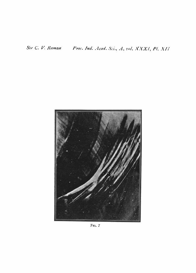
geometric shape (see Plate XI). The structural birefringence in common glasshas thus evidently a similar origin to that observed in the case of vitreoussilica. The similarity of behaviour is even more vividly indicated by thephotograph reproduced as Plate XII, which shows one of the flat walls ofa large glass trough as viewed through a crossed pair of 6" polaroids placedon either side of it.
The photographs reproduced in Plates XI, XII and XIII accompanyingthis paper were obtained by Mr. J. Padmanabban, whose excellent assistancein the investigation 1 have much pleasure in acknowledging. Plate XIV isreproduced from material obtained during an unpublished research byMr. Bawa Kanwal Singh, made at the author's suggestion.
SUMMARY
The result reported in an earlier investigation with vitreous silica is nowshown to be true also for other amorphous solids, including especially in-organic glasses; besides the well-known photo-elastic effect, another kindof birefringence may be observed differing from the former both in itsorigins and in its observable characters. This " structural birefringence "arises from anisotropy of structure present in the solid by reason of the circum-stances of its formation. It is conspicuously seen with plate glass whoseoptical behaviour shows it to have a highly laminated structure, while inmoulded glass, it exhibits itself as luminous streaks or sheets of variouslycurved forms.
Numerous photographs illustrate the paper.
REFERENCE
Raman, C. V. .. Proc. Ind. Acad. Sci. 1950, 31A, 141.
DESCRIPTION OF THE FIGURES
PLATE XI. Birefringence patterns seen between crossed polaroids
FIG. 1. Cube of canary-yellow glass.Figs. 2 & 3. Equilateral prism of glass in two different settings.FIG. 4. Sphere of canary-yellow glass.FIGS. 5 & 6. Cube of glass cut from thick plate in two different sett,ngs.
PLATE XII
Fto. 7. Part of one face of a large glass trough, seen through six-inch polariod sheets,crossed, set on either side çí it,
212 C. V. Raman
PLATE XIII. Plates viewed edgewise, between crossed polaroids
FIG. 8. Quarter-inch thick glass plate, three inches wide.FIG. 9. Same as Fig. 8 but with the quartz wedge superposed.FIG. 10. Quarter-inch glass plate, 11" wide.FIG. 11. Same as Fig. 10 with quartz wedge superposed.FIGS. 12 and 13 ; Same as Figs. 8 and 9, but showing free edge.FIG. 14. One-eighth inch glass plate two inches wide.FIG. 15. Same as Fig. 14 with quartz wedge superposed.FIG. 16. One-sixteenth inch glass plate, 2" wide.FIG. 17. Same as Fig. 16 with quartz wedge superposed.FIG. 18. Quarter-inch plastic sheet, 34" depth.FIG. 19. Same as Fig. 18 with quartz wedge superposed.
PLATE XIV. Photographs of glass block cut from thick plate
FIG. 20. Showing the laminated structure of the block viewed in its plane.FIG. 21. Same as Fig. 20, but with the block tilted slightly.FIGS. 22-25. Glass block seen between crossed polaroids, in various settings, showing
laminations.FIGS. 26 & 27. Glass block with Babinet compensator fringes superposed obliquely, showing
effect of the laminations.
511 C. V. /I?VZ/? J,'o. Iii(/. -I id. A, vol. XXXI. P1. XI
FG 1
1' 2
Fi. 3
1 Jc 4
Fl -, . 5 JG 6
Sir C. V. Raman Pro. Ind. Acad. SW., A, vo/. X XX I, Pl. X II
FIG. 7
Sir C.. V. Raman .Pi'oc. hid. Aa.i'. Sc,., A, vol. XXXI, El. Xl!!
FiG. 9
FIG. 9
FIG. 19
FIG, Ii
Fit. 1
FIG. II
FG. 14
FIG. 15
FIG. i() Fxc. 17
19 FIG. 19
Sir C. V. Raman Proc. I d.. 4'a Sci., A, vol. X X X I, P/. FYI h'
20
FIG. 21
F. 22
Frc• 23
r,^:. 24
Frc;. 25
Fic, 2, Frc. 27


![The Yield-Strain in Shear Banding Amorphous Solids · arXiv:1208.3333v2 [cond-mat.soft] 6 Nov 2012 The Yield-Strain in Shear Banding Amorphous Solids Ratul Dasgupta, H. George E](https://img.pdfslide.us/doc/110x75/5f1086537e708231d4498972/the-yield-strain-in-shear-banding-amorphous-solids-arxiv12083333v2-cond-matsoft.jpg)