Embed Size (px)
Citation preview
BIM
e – Submission Guideline
Structural
While BCA tries to highlight the major points of submission requirements, BCA cannot take into account all the
special cases in other regulatory agencies as well as the changing technology. Updated versions will continue to be
issued to address and incorporate on-going feedback in an open, collaborative process. All readers of this guide are
encouraged to submit feedback to BCA CORENET.
No part of these materials shall be copied, reproduced or published in any form by any means whatsoever electronic
or mechanical including photocopy or by way of any information storage or retrieval system nor should the material
be disclosed to other parties without the expressed written consent and authorization of Building and Construction
Authority.
Information and content set forth in this document are subjected to changes without notice, but will be released as
updates in subsequent version. Readers, who wish to adopt this document as a guide for their own purpose, are
strongly advised to exercise discretionary judgment as neither BCA nor the respective agencies stated in this
document will stand liable to any consequences arising from your adoption.
Building and Construction Authority
5 Maxwell Road #16-00 Tower Block
MND Complex Singapore 069110
www.bca.gov.sg
Revision # Revision Date Summary of Changes Remarks
1.0 October 2010 Issue to Pilot Participants
2.0 April 2011 Revision History incorporated
Updated Table of Contents
Revised as per comments & suggestions of Pilot Users
For official BIM eSubmission
2.1 April 2011 Formatting Changes & Minor Revisions
Description of steps to create content has been
removed and added to Annex 1a and Annex 1b
Copyright @ 2011 Building and Construction Authority
Doc Name: BIM e - Submission Guideline Structural
Current Version: 2.1
Release Date: 15 Apr 2011
If you have any comments, suggestions or clarifications, please write to:
CORENET Team
Building and Construction Authority
5 Maxwell Road
#12-00 Tower Block MND Complex
Singapore 069110
Centre for Construction IT
1F, Block A, ZEB Building
BCA Academy
200 Braddell Rd
Singapore 579700
Contents
1. General Information & Requirements ························································· 4
1.1. BIM e - Submission Packages ···························································· 4
1.2. File Format and Size ········································································ 4
1.3. Project Model Scale ········································································· 5
1.4. Site Layout ····················································································· 5
1.5. Project North Orientation ··································································· 5
1.6. Project Elevation Datum ···································································· 6
1.7. Standardized File Naming ·································································· 7
1.8. Standardised View Naming ································································ 7
1.8.a. View Naming ······································································· 8
1.8.b. Sheet Naming ····································································· 9
1.9. Last Saved Views ············································································ 9
1.10. Addition and Alteration Projects ························································· 10
1.11. Project Resubmission ······································································ 10
1.12. Project Drawings Basic Composition ··················································· 11
1.13. BIM Modeling Workflow ···································································· 12
1.14. Structural BIM e - Submission Checklist ··············································· 13
1. General Information & Requirements
Building Information Modeling (BIM) is a process of generating and managing building information during the
lifecycle of a building/facility. Typically, it involves the use of three-dimensional (3D) building modeling software
to produce a Building Information Model (also abbreviated as BIM), which encompasses building geometry,
spatial relationships, geographic information, quantities and properties of building components.
This document outlines the specifications required to prepare the building information model in BCA BIM e -
Submission format. BCA has worked with the various software vendors to develop “templates” that will help to
manage project information to meet BIM e - Submission format.
1.1. BIM e - Submission Packages
For BIM e - Submission, Qualified Person (QP) is required to compile all drawing views/sheets of a project
into two (2) separate DWF/PDF files for submission.
a) FileName1.pdf/.dwf
This file includes general notes, floor plans, elevations, sections, schedules, and details compiled
in sheets with title block. This file is for approval.
b) FileName2_REF.pdf/dwf
This file includes architectural drawings (floor plans, elevations, sections, etc.), structural 3D
model, structural site plan and supplementary views. This file is for reference only.
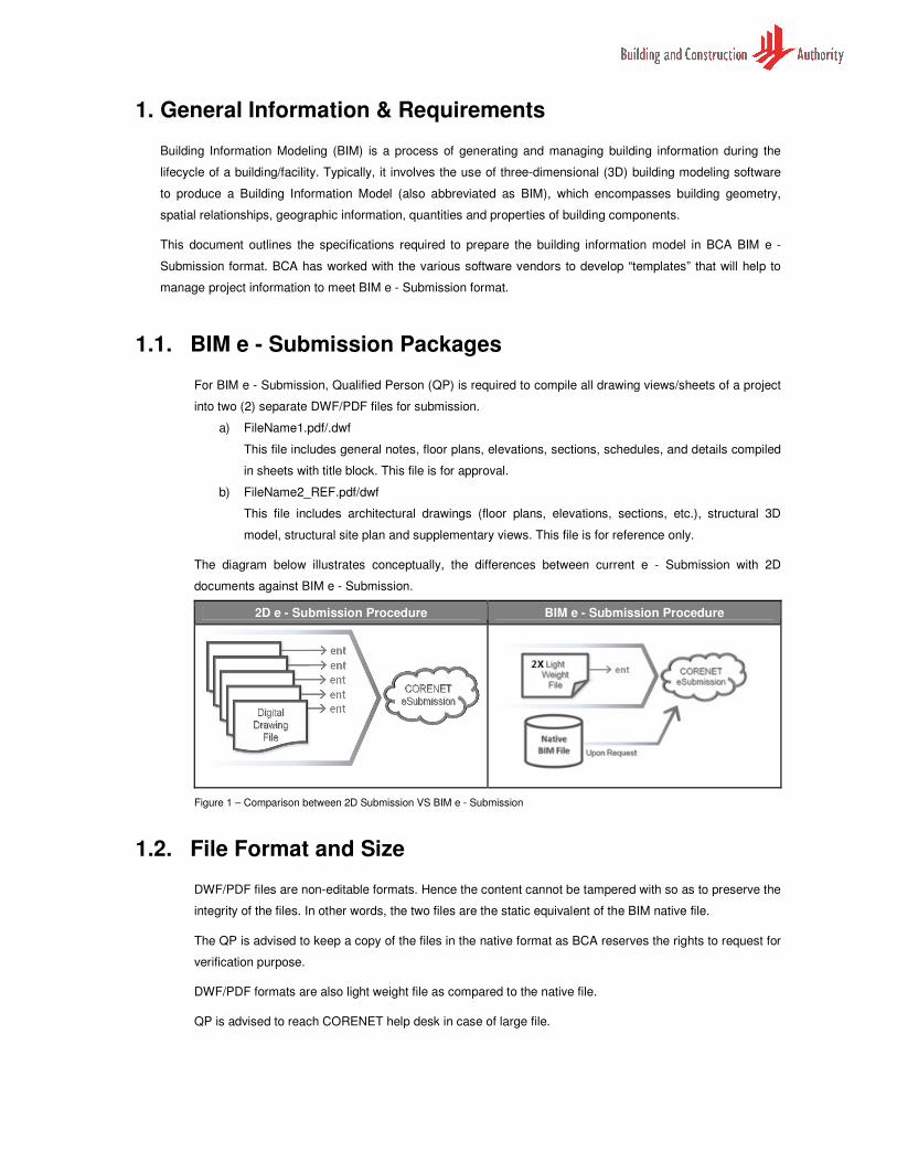
The diagram below illustrates conceptually, the differences between current e - Submission with 2D
documents against BIM e - Submission.
2D e - Submission Procedure BIM e - Submission Procedure
Figure 1 – Comparison between 2D Submission VS BIM e - Submission
1.2. File Format and Size
DWF/PDF files are non-editable formats. Hence the content cannot be tampered with so as to preserve the
integrity of the files. In other words, the two files are the static equivalent of the BIM native file.
The QP is advised to keep a copy of the files in the native format as BCA reserves the rights to request for
verification purpose.
DWF/PDF formats are also light weight file as compared to the native file.
QP is advised to reach CORENET help desk in case of large file.
1.3. Project Model Scale
When modeling a building/structure in the BIM software1, QP is required to create the BIM model in 1:1
scale. QP is also required to use a consistent unit of measurement within the entire BIM model.
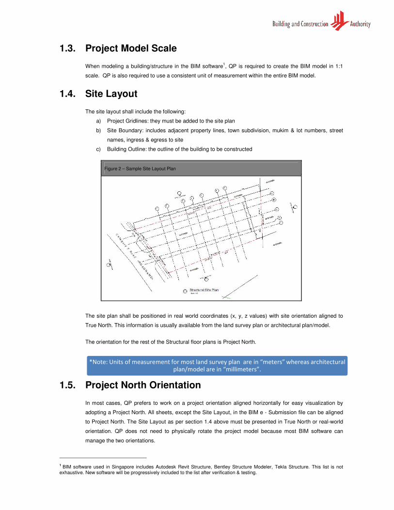
1.4. Site Layout
The site layout shall include the following:
a) Project Gridlines: they must be added to the site plan
b) Site Boundary: includes adjacent property lines, town subdivision, mukim & lot numbers, street
names, ingress & egress to site
c) Building Outline: the outline of the building to be constructed
The site plan shall be positioned in real world coordinates (x, y, z values) with site orientation aligned to
True North. This information is usually available from the land survey plan or architectural plan/model.
The orientation for the rest of the Structural floor plans is Project North.
1.5. Project North Orientation
In most cases, QP prefers to work on a project orientation aligned horizontally for easy visualization by
adopting a Project North. All sheets, except the Site Layout, in the BIM e - Submission file can be aligned
to Project North. The Site Layout as per section 1.4 above must be presented in True North or real-world
orientation. QP does not need to physically rotate the project model because most BIM software can
manage the two orientations.
1 BIM software used in Singapore includes Autodesk Revit Structure, Bentley Structure Modeler, Tekla Structure. This list is not
exhaustive. New software will be progressively included to the list after verification & testing.
*Note: Units of measurement for most land survey plan are in “meters” whereas architectural plan/model are in “millimeters”.
Figure 2 – Sample Site Layout Plan
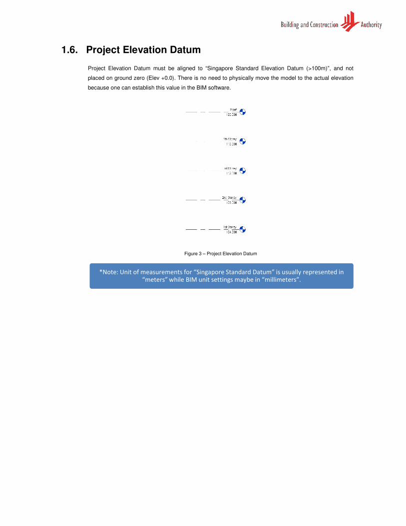
1.6. Project Elevation Datum
Project Elevation Datum must be aligned to “Singapore Standard Elevation Datum (>100m)”, and not
placed on ground zero (Elev +0.0). There is no need to physically move the model to the actual elevation
because one can establish this value in the BIM software.
Figure 3 – Project Elevation Datum
*Note: Unit of measurements for “Singapore Standard Datum” is usually represented in “meters” while BIM unit settings maybe in “millimeters”.
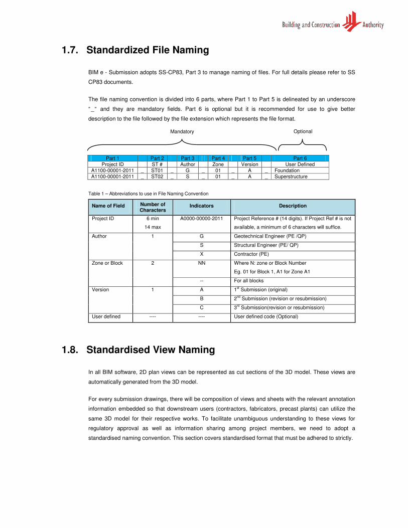
1.7. Standardized File Naming
BIM e - Submission adopts SS-CP83, Part 3 to manage naming of files. For full details please refer to SS
CP83 documents.
The file naming convention is divided into 6 parts, where Part 1 to Part 5 is delineated by an underscore
“_“ and they are mandatory fields. Part 6 is optional but it is recommended for use to give better
description to the file followed by the file extension which represents the file format.
Table 1 – Abbreviations to use in File Naming Convention
Name of Field Number of Characters
Indicators Description
Project ID 6 min
14 max
A0000-00000-2011 Project Reference # (14 digits). If Project Ref # is not
available, a minimum of 6 characters will suffice.
Author 1 G Geotechnical Engineer (PE /QP)
S Structural Engineer (PE/ QP)
X Contractor (PE)
Zone or Block 2 NN Where N: zone or Block Number
Eg. 01 for Block 1, A1 for Zone A1
-- For all blocks
Version 1 A 1st Submission (original)
B 2nd
Submission (revision or resubmission)
C 3rd
Submission(revision or resubmission)
User defined ---- ---- User defined code (Optional)
1.8. Standardised View Naming
In all BIM software, 2D plan views can be represented as cut sections of the 3D model. These views are
automatically generated from the 3D model.
For every submission drawings, there will be composition of views and sheets with the relevant annotation
information embedded so that downstream users (contractors, fabricators, precast plants) can utilize the
same 3D model for their respective works. To facilitate unambiguous understanding to these views for
regulatory approval as well as information sharing among project members, we need to adopt a
standardised naming convention. This section covers standardised format that must be adhered to strictly.
Part 1 Part 2 Part 3 Part 4 Part 5 Part 6
Project ID ST # Author Zone Version User Defined
A1100-00001-2011 _ ST01 _ G _ 01 _ A _ Foundation
A1100-00001-2011 _ ST02 _ S _ 01 _ A _ Superstructure
Mandatory Optional
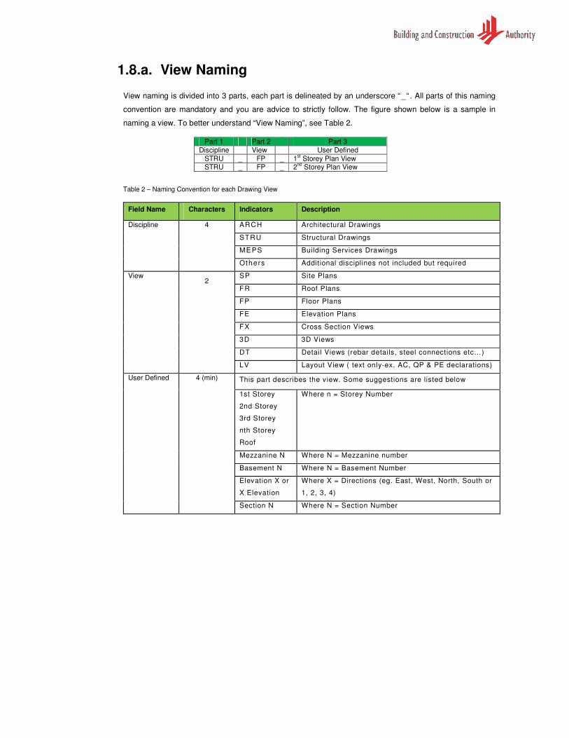
1.8.a. View Naming
View naming is divided into 3 parts, each part is delineated by an underscore “_“ . All parts of this naming
convention are mandatory and you are advice to strictly follow. The figure shown below is a sample in
naming a view. To better understand “View Naming”, see Table 2.
Table 2 – Naming Convention for each Drawing View
Field Name Characters Indicators Description
Discipline 4 ARCH Architectural Drawings
STRU Structural Drawings
MEPS Building Services Drawings
Others Additional disciplines not included but required
View 2
SP Site Plans
FR Roof Plans
FP Floor Plans
FE Elevation Plans
FX Cross Section Views
3D 3D Views
DT Detail Views (rebar details, steel connections etc…)
LV Layout View ( text only-ex. AC, QP & PE declarations)
User Defined 4 (min) This part describes the view. Some suggestions are listed below
1st Storey
2nd Storey
3rd Storey
nth Storey
Roof
Where n = Storey Number
Mezzanine N Where N = Mezzanine number
Basement N Where N = Basement Number
Elevation X or
X Elevation
Where X = Directions (eg. East, West, North, South or
1, 2, 3, 4)
Section N Where N = Section Number
Part 1 Part 2 Part 3
Discipline View User Defined
STRU _ FP _ 1st Storey Plan View
STRU _ FP _ 2nd
Storey Plan View
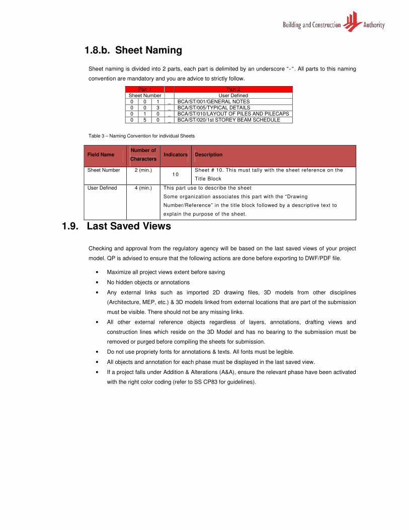
1.8.b. Sheet Naming
Sheet naming is divided into 2 parts, each part is delimited by an underscore “ - “ . All parts to this naming
convention are mandatory and you are advice to strictly follow.
Table 3 – Naming Convention for individual Sheets
Field Name Number of
Characters Indicators Description
Sheet Number 2 (min.) 10
Sheet # 10. This must tally with the sheet reference on the
Title Block
User Defined 4 (min.) This part use to describe the sheet
Some organization associates this part with the “Drawing
Number/Reference” in the title block followed by a descriptive text to
explain the purpose of the sheet.
1.9. Last Saved Views
Checking and approval from the regulatory agency will be based on the last saved views of your project
model. QP is advised to ensure that the following actions are done before exporting to DWF/PDF file.
• Maximize all project views extent before saving
• No hidden objects or annotations
• Any external links such as imported 2D drawing files, 3D models from other disciplines
(Architecture, MEP, etc.) & 3D models linked from external locations that are part of the submission
must be visible. There should not be any missing links.
• All other external reference objects regardless of layers, annotations, drafting views and
construction lines which reside on the 3D Model and has no bearing to the submission must be
removed or purged before compiling the sheets for submission.
• Do not use propriety fonts for annotations & texts. All fonts must be legible.
• All objects and annotation for each phase must be displayed in the last saved view.
• If a project falls under Addition & Alterations (A&A), ensure the relevant phase have been activated
with the right color coding (refer to SS CP83 for guidelines).
Part 1 Part 2
Sheet Number User Defined
0 0 1 _ BCA/ST/001/GENERAL NOTES
0 0 3 _ BCA/ST/005/TYPICAL DETAILS
0 1 0 _ BCA/ST/010/LAYOUT OF PILES AND PILECAPS
0 5 0 _ BCA/ST/020/1st STOREY BEAM SCHEDULE
1.10. Addition and Alteration Projects
Working on A&A projects, it is required to demarcate your 3D model in accordance to SS CP83 Part 5 by
applying color identifier (see Table 1) to all objects. In most BIM software there is no need manually
change the color of these objects; it can be configured virtually through Phase Settings or View
Configuration.
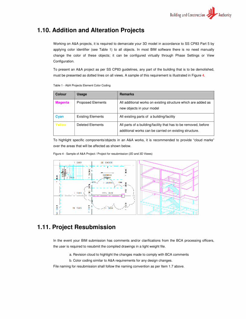
To present an A&A project as per SS CP83 guidelines, any part of the building that is to be demolished,
must be presented as dotted lines on all views. A sample of this requirement is illustrated in Figure 4.
Table 1 - A&A Projects Element Color Coding
Colour Usage Remarks
Magenta Proposed Elements All additional works on existing structure which are added as
new objects in your model
Cyan Existing Elements All existing parts of a building/facility
Yellow Deleted Elements All parts of a building/facility that has to be removed, before
additional works can be carried on existing structure.
To highlight specific components/objects in an A&A works, it is recommended to provide “cloud marks”
over the areas that will be affected as shown below.
Figure 4 - Sample of A&A Project / Project for resubmission (2D and 3D Views)
1.11. Project Resubmission
In the event your BIM submission has comments and/or clarifications from the BCA processing officers,
the user is required to resubmit the compiled drawings in a light weight file.
a. Revision cloud to highlight the changes made to comply with BCA comments
b. Color coding similar to A&A requirements for any design changes.
File naming for resubmission shall follow the naming convention as per Item 1.7 above.
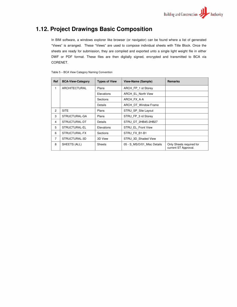
1.12. Project Drawings Basic Composition
In BIM software, a windows explorer like browser (or navigator) can be found where a list of generated
“Views” is arranged. These “Views” are used to compose individual sheets with Title Block. Once the
sheets are ready for submission, they are compiled and exported unto a single light weight file in either
DWF or PDF format. These files are then digitally signed, encrypted and transmitted to BCA via
CORENET.
Table 5 – BCA View Category Naming Convention
Ref BCA-View-Category Types of View View-Name (Sample) Remarks
1 ARCHITECTURAL Plans ARCH_FP_1 st Storey
Elevations ARCH_EL_North View
Sections ARCH_FX_A-A
Details ARCH_DT_Window Frame
2 SITE Plans STRU_SP_Site Layout
3 STRUCTURAL-GA Plans STRU_FP_3 rd Storey
4 STRUCTURAL-DT Details STRU_DT_2HB45-2HB27
5 STRUCTURAL-EL Elevations STRU_EL_Front View
6 STRUCTURAL-FX Sections STRU_FX_B1-B1
7 STRUCTURAL-3D 3D View STRU_3D_Shaded View
8 SHEETS (ALL) Sheets 05 - S_MS/D/01_Misc Details Only Sheets required for current ST Approval.

1.13. BIM Modeling Workflow
This section suggests a modeling workflow within your BIM software. Details may vary from one BIM
platform to another. Please consult you software vendor or IT support.
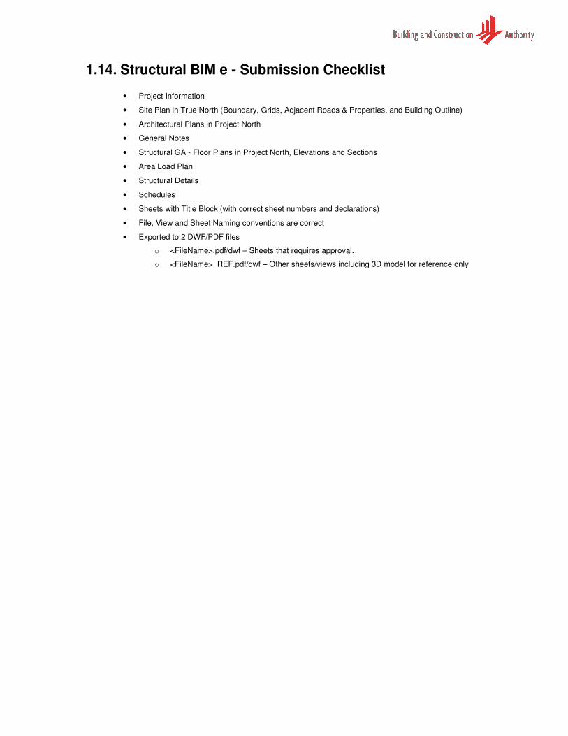
1.14. Structural BIM e - Submission Checklist
• Project Information
• Site Plan in True North (Boundary, Grids, Adjacent Roads & Properties, and Building Outline)
• Architectural Plans in Project North
• General Notes
• Structural GA - Floor Plans in Project North, Elevations and Sections
• Area Load Plan
• Structural Details
• Schedules
• Sheets with Title Block (with correct sheet numbers and declarations)
• File, View and Sheet Naming conventions are correct
• Exported to 2 DWF/PDF files
o <FileName>.pdf/dwf – Sheets that requires approval.
o <FileName>_REF.pdf/dwf – Other sheets/views including 3D model for reference only
Glossary of Acronyms and Terms
The following is a list acronyms and terms used within this document. Take note that some of terms are of local
context and may not have the same connotation when used elsewhere.
No. Acronym / Term Definitions
1 A&A Addition and Alteration
2 AMSL Above Mean Sea Level
3 BIM Building Information Model
4 CAD Computer Aided Drafting
5 CSC Certificate of Statutory Completion
6 DWF File format known as “Design Web Format” that is light-weight and non-editable. Refer to www.autodesk.com for more information
7 IFC Industry Foundation Class. Refer www.iai-singapore.org for more information
8 GFA Gross Floor Area
9 Legend A list of various building components and annotations used in a project
10 QP Qualified Persons / Practitioner. Usually a Professional Engineer (PE)
11 RVT File format created by Revit from Autodesk. Refer to www.autodesk.com for more information
12 SS CP Singapore Standard Code of Practice
13 Sheet The composition area of a CAD drawing environment. Individual sheets are created using the created views from the 3D model and placed inside a Title Block
14 Schedule A tabulated display of information
15 TOP Temporary Occupation Permit
16 View Orientation of the project model from the angle of a viewer, for instance “Floor plan view”, “Elevation view and Sectional view” as well as “3D view”.
17 PDF File format which is light-weight and non-editable, developed by Adobe. Refer to www.adobe.com for more information
18 DGN File format created by Microstation from Bentley. Refer to www.bentley.com for more information
19 DWG File format created by AutoCAD from Autodesk. Refer to www.autodesk.com for more information
20 GA General Assembly. Refer to Floor Plans, Elevations, Section Views etc……
Acknowledgement
A collaborative effort among a panel of knowledgeable Industry Consultants & QPs, Software Vendors and
Processing Officers, has contributed significantly to the successful development of this document. They are:
Regulatory Agency
Building and Construction Authority
� Building Engineering Division
� Special Functions Division, Civil Defence Shelter Engineering Department
Participating Organizations & Software Vendors
� LSW Consulting Engineers Pte Ltd
� ARUP Singapore Pte Ltd
� BECA Carter Hollings & Ferner (SEA) Pte Ltd
� Autodesk Asia Pte Ltd
� Tekla (S) Pte Ltd
� Bentley Systems Pte Ltd.
Notes
As most software gets updated on a regular basis, please contact your software vendor for assistance, if you
encounter difficulties relating to the software products.
Annexes
In conjunction with BIM software developers, BCA has developed a recommend process and template training guide.
� Annex1a – Recommended Process – Revit 2010
� Annex1b – Template Training Guide – Revit 2010
� Further Annex will be added for the respective BIM tools


![GUIDELINE ON SUBMISSION OF DOCUMENTATION … · working document qas/10.373. [draft, 2010-08-10] restricted 1 2 3 4 5 guideline on submission of documentation for a 6 multisource](https://img.pdfslide.us/doc/110x75/5b1580007f8b9a1a398cc225/guideline-on-submission-of-documentation-working-document-qas10373-draft.jpg)