Embed Size (px)
Citation preview

THESIS FOR THE DEGREE OF DOCOTR OF PHILOSOPHY
Structural Behaviour of Deteriorated Concrete Structures
KAMYAB ZANDI HANJARI
Department of Civil and Environmental Engineering Division of Structural Engineering
Concrete Structures CHALMERS UNIVERSITY OF TECHNOLOGY
Gothenburg, Sweden, 2010

Structural Behaviour of Deteriorated Concrete Structures KAMYAB ZANDI HANJARI ISBN 978-91-7385-461-0
© KAMYAB ZANDI HANJARI, 2010
Doktorsavhandlingar vid Chalmers tekniska högskola Ny serie Nr 3142 ISSN 0346-718X Department of Structural Engineering and Mechanics Division of Structural Engineering Concrete Structures Chalmers University of Technology SE-412 96 Gothenburg Sweden Telephone: + 46 (0)31-772 1000 Cover: Results from test and numerical analysis of the eccentric pull-out tests. The main bars were subjected to corrosion and then the corner bar was pulled out. The black parts of the main bars were subjected to corrosion; the red colour indicates cracked concrete. For more information, see page 51 and Paper VII. Chalmers Reproservice Gothenburg, Sweden, 2010


I
Structural Behaviour of Deteriorated Concrete Structures KAMYAB ZANDI HANJARI Department of Civil and Environmental Engineering Division of Structural Engineering, Concrete Structures Chalmers University of Technology
ABSTRACT
A growing concern for better assessment of existing concrete structures has revealed a need for improved understanding of the structural effects of deterioration. The two most common causes of deterioration in concrete structures are freezing of the concrete and corrosion of the reinforcement. The aim of this study is to deepen the understanding of the structural effects of deterioration with special attention to the bond between deformed bars and concrete.
The effects of freezing on the material properties of concrete and the bond behaviour of bars were investigated through experiments. A significant influence of frost damage was observed on the stress-strain response of concrete in compression, tensile stress-crack opening relation, and bond-slip behaviour. Based on this, a set of methods was introduced to predict the mechanical behaviour of reinforced concrete structures with a measured amount of frost damage. The methodology was applied to frost-damaged beams using non-linear finite element analysis at the structural level. The results indicated that the changes in failure mode and the effect on failure load caused by internal frost damage can be predicted by modelling at the structural level.
Corrosion of reinforcement leads to volume expansion of the steel, which can cause cover cracking and spalling; this weakens the bond of the reinforcement. The bond-slip model given in Model Code 1990 was extended to include corroded reinforcement. Analysis of corroded beams using the methodology gave results which are on the safe side. However, for large corrosion penetrations that lead to extensive cover cracking, more detailed modelling of the surrounding concrete and stirrups is required. Under such conditions, when wide cracks develop, the favourable effect of rust flowing through the cracks becomes significant; this decreases the splitting stress around the bar. A previously developed corrosion model was extended to include this phenomenon. The volume flow of rust through a crack was assumed to depend on the splitting stress and the crack width. The splitting stress was evaluated from the strain in the rust, and the crack width was computed from the nodal displacements across the crack. The extended model resulted in more corrosion cracks with smaller crack openings, which better corresponds to the measurements on specimens tested.
Eccentric pull-out tests were carried out to study the influence of cover cracking and stirrups on the bond of corroded bars. The extended corrosion model was used in detailed three-dimensional analyses of the tests. The tests and analyses showed an important effect of the cover cracking in terms of loss of confinement and the flow of rust through the cracks. They also indicated that the bond behaviour and the failure were strongly governed by the position of the anchored bar, i.e. corner or middle positions, and the level of the corrosion attack. Stirrups played an important role after cover cracking, as they then became the primary source of confinement. Furthermore, corrosion of stirrups led to a more extensive cover cracking for a relatively low level of corrosion attack. The knowledge gained in this study contributes to better understanding of the effects of deterioration on structures, and can be used primarily for assessment of the load-carrying capacity of existing structures.
Keywords: concrete, frost, corrosion, stirrup, bond, FE analysis, pull-out test.

II

III
Nedbrutna betongkonstruktioners mekaniska verkningssätt KAMYAB ZANDI HANJARI Institutionen för bygg- och miljöteknik Konstruktionsteknik, Betongbyggnad Chalmers tekniska högskola
SAMMANFATTNING
För att bättre kunna utvärdera befintliga betongkonstruktioner behövs en ökad förståelse av nedbrytningens konstruktionstekniska effekter. De två vanligaste orsakerna till nedbrytning i betongkonstruktioner är frostskadad betong och korrosion av armeringen. Avsikten med detta arbete är att fördjupa förståelsen för nedbrytningens effekt på de konstruktionstekniska egenskaperna, med särskilt fokus på vidhäftningen mellan kamstänger och betong.
Frostskadors effekt på betongs materialegenskaper och på vidhäftning undersöktes experimentellt. Frostskador visades ha stor inverkan på betongens spännings- töjningsrespons i tryck, på responsen i form av spänning och spricköppning i drag, och på sambandet mellan vidhäftningsspänning och glidning. Utifrån dessa resultat utarbetades en metodik för att kunna förutsäga det mekaniska verkningssättet av armerade betongkonstruktioner med en uppmätt frostskada. Metodiken användes på frostskadade balkar i ickelinjära finita elementanalyser. Resultaten visade att förändringar i brottmod och maxlast som orsakats av frostskador kunde förutsägas.
Korrosion av armering leder till volymökning av stålet, vilket kan orsaka uppsprickning och spjälkning av täckskiktet. Därigenom försvagas vidhäftningen mellan armering och betong. En vidhäftningsmodell från “Model Code 1990” vidareutvecklades för att inkludera korroderad armering. Analyser av balkar med korroderad armering gav resultat som var på säkra sidan. För stora korrosionsangrepp krävdes dock mer detaljerad modellering. När stora sprickor utvecklas, kan rost flöda ut genom sprickorna. Detta är en gynnsam effekt då det minskar spjälkspänningarna. En tidigare utvecklad korrosionsmodell vidareutvecklades till att inkludera detta fenomen. Volymsflödet av rost genom en spricka antogs bero på spjälkspänningen och sprickvidden. Spjälkspänningen beräknades från rostens töjning och sprickvidden från noddeformationer tvärs sprickan. Den vidareutvecklade modellen gav resultat med fler men mindre sprickor, vilket stämmer med mätningar som utförts.
Excentriska utdragsförsök utfördes för att kunna studera inverkan av byglar och spruckna täckskikt på korroderade stängers vidhäftning. Den vidareutvecklade korrosionsmodellen användes i detaljerade tredimensionella analyser av försöken. Försöken och analyserna visade en betydande effekt av spruckna täckskikt i form av förlorad omslutningsförmåga och rostflöde genom sprickorna. De visade även att vidhäftningen påverkades mycket av den förankrade stångens position, det vill säga om det var en hörnstång eller en mittstång, och av graden av korrosionsangrepp. Byglar var viktiga efter att täckskiktet spruckit, eftersom de då blev primär orsak till omslutning. Vidare resulterade korrosion av byglar i omfattande uppsprickning av täckskiktet redan för ganska små korrosionsangrepp. Kunskapen som erhållits i detta arbete bidrar till en bättre förståelse av nedbrytningseffekter på konstruktioner, och kan främst användas vid utvärdering av befintliga betongkonstruktioners bärförmåga.
Nyckelord: betong, frost, korrosion, byglar, vidhäftning, finit elementanalys, utdragsförsök.

CHALMERS, Civil and Environmental Engineering IV
Contents ABSTRACT I
SAMMANFATTNING III
CONTENTS IV
PREFACE VI
NOTATION XII
1 INTRODUCTION 1
1.1 Background 1
1.2 Aim, scope and limitations 2
1.3 Original features 3
1.4 Outline of the thesis 4
2 FROST-DAMAGED CONCRETE STRUCTURES 5
2.1 Background 5
2.2 Mechanism of frost damage 5
2.3 Effects of frost on the material properties of concrete 6
2.4 Effects of frost on bond behaviour 9
2.5 Mechanical behaviour of frost-damaged concrete structures 10
2.6 Modelling the effects of frost on the structural level 12 2.6.1 Plane-stress analysis 12 2.6.2 Beam-element analysis 13
3 OVERVIEW OF CORRODED REINFORCED CONCRETE STRUCTURES 15
3.1 Background 15
3.2 Uniform and pitting corrosion 16
3.3 Properties of corroded steel bars 17
3.4 Bond between corroded reinforcement and concrete 18
3.5 Mechanical behaviour of corroded reinforced concrete structures 20
3.6 Modelling the effects of corrosion on the structural level 22 3.6.1 Plane-stress analysis 23 3.6.2 Hand calculations 24
4 THREE-DIMENSIONAL MODELLING OF CORROSION 27
4.1 Background 27
4.2 The bond model 28
4.3 The corrosion model 29
4.4 Further development of the corrosion model 30
CHALMERS, Civil and Environmental Engineering V
5 CRACKING AND BOND DETERIORATION DUE TO CORROSION 37
5.1 Background 36
5.2 Effects of corroded stirrups 38
5.3 Modelling of corrosion leading to cover spalling 41
5.4 Eccentric pull-out tests 44
5.5 Three-dimensional modelling of eccentric pull-out tests 48
6 CONCLUSIONS 53
6.1 General conclusions 53
6.2 Suggestions for future research 55
7 REFERENCES 57

CHALMERS, Civil and Environmental Engineering VI
Preface The work presented in this thesis was carried out from April 2006 to December 2010 at the Department of Civil and Environmental Engineering, Division of Structural Engineering, Concrete Structures, Chalmers University of Technology. The study was made possible by the financial support of the former Swedish Road Administration and Swedish Rail Administration, now both the Swedish Transport Administration. Part of the experimental work was done in collaboration with SP (Technical Research Institute of Sweden), and a part was conducted at Politecnico di Milano.
It was a great privilege to do research at Chalmers under the supervision of Associate Professor Karin Lundgren, Assistant Professor Mario Plos, Professor Kent Gylltoft, and Per Kettil, Ph.D., Skanska Sverige AB. I am most grateful to Karin Lundgren, whose experience and knowledge of my topic were invaluable. She always trusted me when I said “I can”, even when I sounded uncertain. I could see that she enjoyed watching me become a researcher during these years, which I will never forget. I am very thankful to Mario Plos for being always willing to give comments and discuss the work. He always read drafts with great interest and had brilliant comments. He made a major effort when I was searching for naturally corroded specimens. Special thanks go to Kent Gylltoft, who was also my examiner, for his valuable discussions, comments and encouragement throughout the work, and for building a creative research environment at the division. Thanks also go to Per Kettil, who was involved in an early stage of the thesis work, for being very caring and patient.
Assistant Professor Dario Coronelli, at Politecnico di Milano, had a great impact on my work and his contributions were very valuable. Tough work does not scare him away; it inspires him day and night. His knowledge, his insistence on hard work, and his friendly personality made the collaboration flourish. Professor Gambarova, despite his many engagements, commented on the experiments; he truly is the “Leonardo da Vinci” of his department. I am grateful to both of them for hosting me in Milan as well as financing the experimental work.
Peter Utgenannt, Ph.D., SP/CBI, deserves my gratitude for offering his valuable experience when planning the experiments dealing with frost and for conducting a major part of the testing at SP. I also would like to thank Jonas Magnusson, Ph.D., NCC, who took a great interest in my work and commented on the test set-up and results very thoroughly. I appreciate the members of the reference group meetings, Björn Engström from Chalmers; Robert Ronnebrant, Ebbe Rosell, Valle Janssen, and Mudaher H. Mushin from the Swedish Transport Administration; and Mette Sloth, Poul Linneberg and Marianne Tange Hasholt from COWI, Denmark, for stimulating discussions and for taking an interest of my work. I would like to extend my thanks to laboratory technicians Lars Wahlström at Chalmers, Gert-Olof Johansson at SP, and Marco Lamperti Tornaghi at Politecnico di Milano. Furthermore, I am grateful to all of my colleagues and friends for being supportive during this time. Special thanks go to Yvonne Juliusson and Lisbeth Trygg for their kind support. I am thankful to Lora Sharp McQueen for language editing this thesis very thoroughly.
Finally, my wife Adele, who constantly embraces me with an ocean of care, is supportive, adoring and thoughtful. She eagerly listens, questions and comments. She is deep and complex. She wants to be the best, while she already is. She continuously redefines as POSSIBLE what once was impossible.
K. Zandi Hanjari, Gothenburg, November, 2010

CHALMERS, Civil and Environmental Engineering VII

CHALMERS, Civil and Environmental Engineering VIII
LIST OF PUBLICATIONS
This thesis is based on the work contained in the following papers, referred to by Roman numerals in the text. The articles dealing with frost-damaged concrete are listed first, followed by the ones dealing with corroded reinforcement.
I. Zandi Hanjari, K., Utgenannt, P. and Lundgren, K. (2009). Experimental study of the material and bond properties of frost-damaged concrete, Accepted for publication in Cement and Concrete Research.
II. Zandi Hanjari, K., Kettil, P. and Lundgren, K. (2010). Modeling the structural behavior of frost-damaged reinforced concrete structures, submitted to Structure and Infrastructure Engineering.
III. Lundgren, K., Kettil, P., Zandi Hanjari, K., Schlune, H. and San Roman,
A. S. (2009). Analytical model for the bond-slip behaviour of corroded ribbed reinforcement, Accepted for publication in Structure and Infrastructure Engineering.
IV. Zandi Hanjari, K., Kettil, P. and Lundgren, K. (2008). Analysis of the
mechanical behavior of corroded reinforced concrete structures, submitted to ACI Structural Journal.
V. Coronelli, D., Zandi Hanjari, K. and Lundgren, K. (2010). Severely
corroded reinforced concrete with cover cracking, submitted to Materials and Structures.
VI. Zandi Hanjari, K., Coronelli, D. and Lundgren, K. (2010). Bond capacity
of severely corroded bars with corroded stirrups, submitted to Magazine of Concrete Research.
VII. Zandi Hanjari, K., Lundgren, K., Plos, M. and Coronelli, D. (2010). Three-
dimensional modeling of corroded reinforcement in concrete, submitted to Structure and Infrastructure Engineering.

CHALMERS, Civil and Environmental Engineering IX
AUTHOR’S CONTRIBUTION TO JOINTLY PUBLISHED PAPERS
The contributions of the author of this doctoral thesis to the appended papers are described here.
I. Responsible for the planning and writing of the paper. Shared responsibility in the planning and conducting the experiments. Carried out the inverse analyses.
II. Participated in the planning and writing of the paper. Responsible for the development of the methodology. Carried out the FE analyses.
III. Participated in the discussion of the methodology. Contributed comments on the results and paper.
IV. Responsible for the main part of the planning and writing of the paper.
Participated in the development of the methodology. Carried out the FE analyses.
V. Participated in the planning and writing of the paper.
Participated in the planning and conducting the experiments. Carried out the FE analyses.
VI. Responsible for the planning and writing of the paper. Shared responsibility in the planning and conducting the experiments. Carried out the FE analyses.
VII. Responsible for the planning and writing of the paper. Responsible for the development of the model. Implemented the model in a FE code. Carried out the FE analyses.

CHALMERS, Civil and Environmental Engineering X
OTHER PUBLICATIONS RELATED TO THE THESIS
Licentiate Thesis
Zandi Hanjari, K. (2008). Load-Carrying Capacity of Damaged Concrete Structures. Licentiate Thesis No. 2008:06, Department of Civil and Environmental Engineering, Chalmers University of Technology, Göteborg, Sweden, 98 pp.
Conference Papers
Coronelli, D., Zandi Hanjari, K., Lundgren, K. and Rossi, E. (2010). Severely corroded reinforced concrete with cover spalling: Part 1. Crack initiation, crack propagation and cover delamination. Joint Fib-RILEM Workshop on Modelling of Corrosion Concrete Structures, 22–23 Nov., Madrid, Spain.
Zandi Hanjari, K., Lundgren, K. and Coronelli, D. (2010). Severely corroded reinforced concrete with cover spalling: Part 2. Anchorage capacity. Joint Fib-RILEM Workshop on Modelling of Corrosion Concrete Structures, 22–23 Nov., Madrid, Spain.
Zandi Hanjari, K., Utgenannt, P. and Lundgren, K. (2009). Frost-damaged concrete: Part 1. Material properties. The 4th International Conference on Construction Materials: Performance, Innovations and Structural Implications, 24–26 Aug., Nagoya, Japan, pp. 753–760.
Zandi Hanjari, K., Utgenannt, P. and Lundgren, K. (2009). Frost-damaged concrete: Part 2. Bond properties. The 4th International Conference on Construction Materials: Performance, Innovations and Structural Implications, 24–26 Aug., Nagoya, Japan, pp. 761–766.
Zandi Hanjari, K., Lundgren, K., Kettil, P. and Plos, M. (2008). Structural behavior of corroded reinforced concrete structures. The Fourth International Conference on Bridge Maintenance, Safety, Management, Health Monitoring and Informatics, 13–17 July, Seoul, South Korea, pp. 481.
Zandi Hanjari, K., Lundgren, K., Plos, M., Kettil, P. and Gylltoft, K. (2008). Evaluation of load-carrying capacity of damaged reinforced concrete structures. The Proceedings of the Nordic Concrete Research & Development, 8–11 June, Bålstad, Sweden, pp. 60.
Zandi Hanjari, K., Lundgren, K., Kettil, P., Gylltoft, K. and Plos, M. (2008). Performance evaluation of damaged concrete bridges. The 3rd International Bridge Conference, 27–29 May, Tehran, Iran.
Lundgren, K., Soto San Roman, A., Schlune, H., Zandi Hanjari, K. and Kettil, P. (2007). Effects on bond of reinforcement corrosion. The Proceedings of the International RILEM Workshop on Integral Service Life Modeling of Concrete Structures, 5–6 Nov., Guimarães, Portugal, pp. 231–238.
Zandi Hanjari, K., Kettil, P. and Lundgren, K. (2007). Mechanical behaviour of Frost-damaged reinforced concrete structures. The Proceedings of the 6th International Conference on Fracture Mechanics of Concrete and Concrete Structures, 17–22 June, Catania, Italy, pp. 1761–1766.

CHALMERS, Civil and Environmental Engineering XI
Reports
Zandi Hanjari, K. and Coronelli, D. (2010). Anchorage Capacity of Corroded Reinforcement: Eccentric Pull-out Tests. Report No. 2010-06. Department of Civil and Environmental Engineering, Chalmers University of Technology, Göteborg, Sweden, Dipartimento di Ingegneria Strutturale, Politecnico di Milano, Milan, Italy.
Zandi Hanjari, K. (2008). Material and Bond Properties of Frost-Damaged Concrete. Report No. 2008:10. Department of Civil and Environmental Engineering, Chalmers University of Technology, Göteborg, Sweden.

CHALMERS, Civil and Environmental Engineering XII
Notation
Roman upper case letters
Area
crA Section area of the crack
pitA Section area of pitting corrosion
11D Stiffness in the elastic stiffness matrix in the radial direction
22D Stiffness in the elastic stiffness matrix in the longitudinal direction
33D Stiffness in the elastic stiffness matrix in the tangential direction
Dynamic modulus of elasticity for frost-damaged concrete
F Load
1F Yield line describing friction
2F Yield line describing the upper limit at a pull-out failure I Impressed current in artificial corrosion
corK Stiffness of rust in the radial direction
P Depth of pitting corrosion
V Volume flow of rust
Roman lower case letters
b Width of pitting corrosion c Stress in the inclined compressive struts; or concrete cover d Superscript: (related to) frost damaged concrete e Element size
ccf Compressive strength of concrete
crackedcf , Compressive strength of concrete cracked by corrosion
Compressive strength of frost-damaged concrete
Tensile strength of concrete d
ctf Tensile strength of frost-damaged concrete
i Subscript: time increment number k Model parameter in the one-dimensional bond-slip relation p Exponent describing the granular behaviour of rust r Radius of bar s Slip t Corrosion time u Relative displacements across the interface
nu Relative normal displacement at the interface
nbondu Normal deformation in the bond layer
ncoru Normal deformation in the corrosion layer
ru Relative displacements in the direction around the bar
A
dDE
dccf
ctf

CHALMERS, Civil and Environmental Engineering XIII
tu Slip
tcoru Slip in the corrosion layer v Velocity of rust particles
crww, Crack opening
x Corrosion penetration y Free increase of the bar radius in the original corrosion model
exty Free increase of the bar radius in the extended corrosion model
Greek letters
t Time increment V Volume flow of rust in a time increment
Deformation Strain of concrete
c Strain at peak compressive stress in concrete
cc Compressive strain in concrete
Strain at peak compressive stress in concrete cracked by corrosion
cor Total strain in rust
ct Tensile strain in concrete
Angles in calculation of the pitting corrosion area Angle of a shear crack
Coefficient of friction
Compressive stress in concrete
Tensile stress in concrete
n Normal splitting stress
r Stress in the direction around the bar
t Bond stress
Bond stress
rs Volume rust/volume steel
Remaining diameter of a uniformly corroded bar
0 Original diameter of a bar
crackedc,
21,
cc
ct


CHALMERS, Civil and Environmental Engineering 1
1 Introduction 1.1 Background Nowadays, concrete is one of the most commonly used structural materials. Many 20th century concrete structures may already be deteriorated. It is therefore important to focus on the assessment of existing structures, since an optimized maintenance and repair method involves the capability to predict the structural behaviour and remaining service life of deteriorating structures. On-site investigation of concrete structures may be necessary for a wide variety of reasons usually associated with the assessment of specification compliance, maintenance requirements or structural adequacy. Moreover, there have been substantial changes in the traffic flow and loading of roads so that many bridges are bearing loads for which they were not designed. The characteristics of concrete and the types of steel used for reinforcement or prestressing have also changed, as well as design methods and site construction procedures.
When deterioration is detected during inspections, it is documented. For severely deteriorated structures, parameters which influence the structural behaviour must be determined, for example by measuring material properties and making drawings of places where splitting of the covers has occurred. Based on these types of information, models are needed to study the behaviour of the deteriorated structure, and also to predict the load-carrying capacity; this applies whether or not the structure has been repaired. However, such models are scarce. Consequently, there is a growing need for better understanding of the effects of deterioration in order to enable the development of models which can be used to study the structural behaviour of deteriorated structures.
The most severe types of deterioration in concrete structures are associated with the volume expansion of reinforcing bars and of concrete, namely reinforcement corrosion and frost-damaged concrete, respectively. Frost damage in concrete is caused by: (a) the difference in thermal expansion of ice and concrete, leading to superficial damage known as surface scaling; and (b) the volume expansion of freezing water in the concrete pore system, resulting in a severe type of damage known as internal frost damage, see Chatterji (1999). Both types of frost damage may influence the bond behaviour of an anchored bar, see Fagerlund et al. (1994). Surface scaling results in spalling of the concrete cover, which means that less confinement is available to the bar, see Fagerlund et al. (2001). Internal frost damage affects the bond behaviour of a bar by causing several micro and macrocracks and changing the compressive and tensile strength of concrete, see Fagerlund (2004) and Petersen et al. (2007).
The corrosion process transforms steel into rust, causing: (a) reduced area and ductility change of the reinforcement bars, and (b) volume expansion generating splitting stresses in the concrete, which may crack the concrete cover and affect the bond between reinforcement and concrete. This has been studied by many researchers; for a state-of-art see fib (2000). For larger corrosion penetrations, the splitting stresses may lead to cover spalling which alters the resisting mechanism in the cross section; stirrups then become the primary source of confinement.
The interaction between reinforcement and the surrounding concrete is fundamental in reinforced concrete structures. It is important for the load-carrying capacity and

CHALMERS, Civil and Environmental Engineering 2
ductility in the ultimate state, as well as for the stiffness and distribution of cracks in the service state.
In the assessment of deteriorated structures, hand calculations and numerical analyses can be used to calculate the load-carrying capacity of a deteriorated structure. For example, hand calculations may be sufficient for assessing the bending capacity, while the ductility can be better described by using a numerical model. Furthermore, numerical modelling can be carried out at different levels. A whole structure can be modelled using simplified linear or non-linear structural analysis with beam elements, shell elements or both, and embedded reinforcement that corresponds to full interaction. Simple modelling and reduced analysis time are the two advantages of such an analysis. This allows the model to be easily changed and to handle more alternatives. The effects of damage can be included by assigning decreased stiffness and strength values to damaged regions and by comparing load effects, i.e. moments and shear forces, with the capacities of damaged cross-sections. This level of analysis is referred to as “beam-element analysis” in this thesis. Examples of hand calculations and beam-element analysis are described in Sections 3.6.2 and 2.6.2, respectively.
More complex failure modes, such as shear and anchorage, require more detailed modelling of the bond-slip behaviour and shear reinforcement. At this level of modelling, non-linear analysis using two-dimensional solid (continuum) elements, e.g. plane stress elements, can be carried out. The main reinforcement is modelled with truss elements and the interaction between the main bar and concrete is described by a one-dimensional bond-slip relation. The effects of damage can be included by modifying the concrete cross-section, the response of the materials in tension and compression, and the bond-slip relation. This level of analysis is referred to as “plane-stress analysis” in this thesis and two examples of such an analysis are presented in Sections 2.6.1 and 3.6.1.
In structural non-linear analysis at a detailed level, concrete and reinforcement are modelled with three-dimensional solid elements. The interaction between reinforcement and concrete can also be simulated in more detail with surface interface elements. Although detailed structural analyses are numerically expensive, they allow for a better description of the behaviour at both the material and structural levels. This type of detailed structural analysis is referred to as “three-dimensional analysis” in this thesis; examples of such analyses are given in Chapter 5.
1.2 Aim, scope and limitations This study aims to improve the understanding of the structural behaviour of deteriorated concrete structures with special attention to the bond between deformed bars and concrete. The research presented here deals with the two most common causes of deterioration due to environmental impacts, which are corrosion of reinforcement and freezing of concrete. However, the study is not extended to evaluate the combined effects of corrosion and frost on structures. Moreover, time dependent effects, creep and shrinkage, were not included in the analyses presented in this thesis.
Laboratory experiments and non-linear finite element analyses were combined to study the structural effect of frost damage. These were complemented with tests described in the literature and a set of methods was introduced to predict the mechanical behaviour of reinforced concrete structures with a measured amount of
CHALMERS, Civil and Environmental Engineering 3
frost damage at a given time. The development of frost deterioration over time was not included. The part of the proposed methodology dealing with surface scaling due to frost could not be validated with previous experiments, as no study could be found in which the structural effect of surface scaling has been experimentally investigated.
The effects of corrosion on the structural behaviour of reinforced concrete structures were studied in depth. First, a set of methods was devised to analyze the mechanical behaviour of a structure with an observed amount of uniform and pitting corrosion at a given time; the development of corrosion damage over time was not included. Next, an extensive experimental program and detailed structural analyses were carried out to study the bond of a corroded bar. Both tests and analyses were focused on high corrosion penetrations leading to extensive cover cracking and also including the effect of corroded stirrups. The study was limited to the anchorage of a bar at an end region; i.e. it was not extended to cut-off and splice regions.
Moreover, accelerated methods were used for corroding the specimens. The extended corrosion model was also calibrated with respect to test specimens corroded with similar methods. Therefore, the results should be treated with caution when they are applied to naturally corroded structures. The results and knowledge gained through this research will be useful to assess existing structures, and for professionals such as researchers and practising engineers.
1.3 Original features The effects of frost on material properties of concrete and bond behaviour of deformed bars were investigated through experiments. There is very little information concerning the softening behaviour of frost-damaged concrete in the literature; moreover, the limited available knowledge is not experimentally validated. The bi-linear tensile stress-crack opening relation estimated through inverse analysis of wedge splitting test results is believed to be the only available estimation made from experiments.
The principle of the methodology proposed for frost-damaged concrete is that the effect of frost can be modelled by adapting material and bond properties and by modifying geometry. Although suggestions for adjusting the material and bond properties of frost-damaged concrete have already been given by other researchers, their application to concrete beams in ultimate state has not been done before.
The effect of reinforcement corrosion on the bond mechanism is studied in detail through experiments and analyses. A simple analytical model to predict the bond-slip behaviour for corroded bars is proposed; this is used as input for structural analysis to assess existing structures. A previously developed corrosion model on a more detailed level was extended to include the favourable effect of rust flowing through a crack. The fundamentals of the development are based on mass transportation, assuming that the volume flow of rust depends on the splitting stress around the corroding bar and the crack width. This method of describing the phenomenon has not, to the author’s knowledge, been taken into account before.
The eccentric pull-out tests carried out to study the combined influence of large corrosion penetrations and corroded stirrups are believed to be unique; no tests have been found in the literature that show the effect of corroding stirrups on cover cracking.

CHALMERS, Civil and Environmental Engineering 4
The effect of shear reinforcement has usually been included in finite element analyses with simplifying assumptions; for example, full interaction between stirrups and concrete has commonly been assumed. Furthermore, the effect of the corrosion of stirrups on cover cracking has been overlooked in numerical analysis. Detailed non-linear finite element analysis of test specimens with three-dimensional modelling of corroded stirrups is another feature of this work.
1.4 Outline of the thesis The thesis consists of seven papers and an introductory part which gives a comprehensive background to the subjects treated in the papers. In Chapter 1 the aim, scope and limitations of the work together with a description of the original features are given. Chapter 2 and Papers I and II present a general background on the mechanisms of frost damage. Material and bond properties of frost-damaged concrete and the effect of frost on the load-carrying capacity of concrete structures are discussed. A methodology to calculate the load-carrying capacity of frost-damaged concrete structures is introduced based on experiments carried out by the author and other researchers. The methodology is applied to estimate the residual load-carrying capacity of frost-damaged beams reported in the literature and, finally, the results are compared with experimental results given in Paper.II.
In Chapter 3 and Papers III and IV, the material properties of corroded reinforcement, from a literature study, are collected and studied. The bond behaviour of corroded reinforced concrete structures is investigated, and an analytical one-dimensional model for the bond-slip response of corroded reinforcement is proposed in Paper III. A methodology to analyze the mechanical behaviour and the remaining load-carrying capacity of corroded reinforced concrete structures is suggested. The proposed approach is used to analyse beams, using both analytical methods and non-linear finite element analysis, after which the results are compared with experiments given in Paper IV.
Chapter 4 and Paper VII deal with three-dimensional modelling of corrosion in finite element analysis. First, two previously developed bond and corrosion models are briefly discussed. Next, the principles of further development of the corrosion model to account for the effect of rust flowing through a crack are described.
Chapter 5 and Papers V, VI and VII describe the eccentric pull-out tests carried out to study the influence of large corrosion penetrations and corroded stirrups. The influence of corrosion that leads to extensive cover cracking, together with the crack pattern and crack width from numerical analysis, is presented in Paper V. The influence of corrosion on the bond behaviour of an anchored bar, together with the results of numerical analysis using the original and the extended corrosion models, are given in Papers VI and VII. The conclusions and suggestions for future research are given in Chapter 6.

CHALMERS, Civil and Environmental Engineering 5
2 Frost-damaged Concrete Structures 2.1 Background Environmental impacts affect the serviceability and the load-carrying capacity of concrete structures. Many researchers have been concerned with the various types of environmental impacts, such as corrosion of reinforcement, alkali-silica reaction, and sulphate attack, but relatively little attention has been given to the problem of assessing the mechanical behaviour of frost-damaged concrete structures. Some studies have investigated the mechanisms of frost deterioration, see Beaudoin and MacInnis (1974), Chatterji (1999), and Valenza and Scherer (2006), while others have numerically modelled the effects of freezing and thawing on porous solids at a material level, see Zuber and Marchand (2000), and Kruschwitz and Bluhm (2005). Another group of experimental studies focused on the influence of frost on the material properties of concrete, see Fagerlund (2004), Hasan et al. (2004), Shang and Song (2006), and Hasan et al. (2008), and on the steel-concrete bond, see Shih et al. (1988), Fagerlund et al. (1994), and Petersen and Lohaus (2004). A few studies have been devoted to the structural response of frost-damaged concrete structures, including panels and slabs, see Mohamed et al. (2000), and Tang and Petersson (2004), and beams, see Hassanzadeh and Fagerlund (2006), and Petersen et al. (2007). However, most of the previous numerical and analytical studies have focused on the mechanical behaviour of frost-damaged structures in the service limit state.
The material properties of concrete are influenced by frost deterioration. Consequently, frost damage may alter the structural response. Hassanzadeh and Fagerlund (2006), who carried out bending tests on beams subjected to freezing and thawing cycles, observed that when concrete is severely damaged by frost, there may be a stiffness reduction in the serviceability limit state, and a dramatic reduction of the load-carrying capacity, including a change of failure mode, in the ultimate limit state. The structural response of frost-damaged beams in terms of moment-curvature relation was also experimentally and numerically investigated by Petersen et al. (2007); the freezing-and-thawing-induced change in tension stiffening was discussed. It was found that the distribution of the internal damage may not be constant over a concrete section, and that this may influence the behaviour of a damaged section to a rather large extent.
This chapter explains a methodology to analyze the mechanical behaviour, e.g. strength and stiffness, of reinforced concrete structures affected by frost damage. The methodology is based on experiments carried out by the author, see Paper I and Zandi Hanjari (2008b), and other researchers. The work is restricted to the estimation of the mechanical behaviour for a structure with a measured amount of damage at a given time; hence, the development of frost-damage over time is not included. The proposed methodology was formulated and applied to concrete beams affected by internal frost damage, using non-linear finite element analyses, Paper II.
2.2 Mechanism of frost damage Frost damage in concrete is caused by the difference in thermal expansion of ice and concrete and by the volume expansion of freezing water in the concrete pore system, see Valenza and Scherer (2006). The former mechanism is involved when the concrete structure is subjected to cold climates in the presence of saline water. The

CHALMERS, Civil and Environmental Engineering 6
stress arises from the difference in thermal expansion of ice and concrete, which leaves the ice in tension as the temperature drops; a crack in brine ice penetrates into the substrate and causes the superficial damage known as surface scaling. This damage usually results in spalling of the concrete surface, while the remaining concrete is mostly unaffected, see Wiberg (1993), Gudmundsson and O. Wallevik (1999), and Fagerlund (2004).
If the volume expansion of freezing water cannot be accommodated in the pore system; it will be restrained by the surrounding concrete. Tensile stresses are thereby initiated and micro and macrocracks take place in the concrete body, which leads to the type of severe damage known as internal frost damage. This mechanism affects both compressive and tensile strength, elastic modulus and the fracture energy of the concrete, as well as the bond strength between the reinforcement and surrounding concrete in damaged regions, see Powers (1945), Shih et al. (1988), and Fagerlund et al. (2001).
There exist several other mechanisms to explain frost phenomena in concrete, such as “Freezing of a closed container”, “Hydraulic pressure”, “Microscopic and macroscopic ice lens growth” among others; for a detailed discussion see Fagerlund et al. (2001). Although none of the mechanisms were proved to explain the phenomena involved completely, each contributes to some aspects of frost damage in concrete. Thorough discussion on the various mechanisms of frost is not within the scope of this thesis. However, it should be mentioned that some cycles of freezing and thawing are required before frost damage occurs in concrete; this is a common statement in all the mechanisms mentioned above. Moreover, the level and distribution of damage in a concrete section are determined by the degree of saturation of concrete. Hence, frost damage depends not only on environmental conditions, such as freezing and thawing cycles and relative humidity; it is also influenced by the internal structure of concrete, e.g. porosity.
Concrete made with a low water-cement ratio and a proper air-void system is relatively resistant to frost damage, see ACI (2007). However, the damage may be accelerated by exposure to moisture or by the use of deicing salt. Too little entrained air does not protect concrete against frost damage, and too much air reduces the concrete strength. Specifications on the content of air for different exposure conditions are given in codes, see ACI (2007), and EuroCode2 (2004).
2.3 Effects of frost on the material properties of concrete The primary step in the assessment of an existing structure subjected to freeze-thaw cycles is to quantify the level of damage. Frost damage can be quantified in terms of the number of freeze-thaw cycles, a change in the relative dynamic modulus of elasticity or a change in material properties such as compressive strength. As explained before, it is the degree of saturation of concrete that influences the level of frost damage. Hence, the damage depends on both the internal structure of concrete and the number of freeze-thaw cycles. There are several research publications in which the frost damage has been quantified by the number of freeze-thaw cycles, see Shih et al. (1988), Gong et al. (2005), and Ji et al. (2008). On the other hand, frost damage changes the internal structure of concrete, for example by, initiating micro and macrocracks. Any change in the internal structure of concrete affects its material properties and lengthens the travel time of an ultrasonic wave passing through it. For

CHALMERS, Civil and Environmental Engineering 7
this reason, changes in the compressive strength of concrete and in the relative dynamic modulus of elasticity were used as the indicators of damage in this study, as well as in some other research work, see Hasan et al. (2004), Petersen et al. (2007), and Sun et al. (1999). A correlation between the two damage indicators is shown in Figure 1.
Compressive strength, fccd (MPa)
0 20 40 60 80
Dyn
amic
mod
ulus
of
elas
tici
ty,
ED
d (G
Pa)
0
20
40
60
80Suzuki et al. (2007)Paper IFagerlund et al. (1994)Shang et al. (2006)Regression
cd
cc
dD
bf
aE
)(1
3.3 4.30 8.52 cba
Figure 1. Correlation between the compressive strength and the dynamic modulus of elasticity for frost-damaged concrete, (Paper II).
For undamaged concrete, relations between compressive strength and tensile strength are well-established, see CEB-FIP (1993), ACI (2007), and EuroCode2 (2004), and widely used. To find a similar relation for frost-damaged concrete, test results for the tensile strength of undamaged and frost-damaged concrete were adapted and plotted versus the corresponding compressive strength; the results was then compared with relations for undamaged concrete, Figure 2(a). The tensile strength of the damaged concrete is markedly lower than if it had been estimated from the relations for undamaged concrete. By curve fitting, although the scatter is large, the following relation for the damaged concrete was suggested in Paper II:
2.1 )(027.0 dccct ff (1)
where fctd is the tensile strength of the damaged concrete, and fcc
d is the measured compressive strength of the damaged concrete in MPa for a standard 150 × 300 mm cylinder.
The proposed relationship was compared with experimental work carried out by other researchers, see Hassanzadeh and Fagerlund (2006), and Shang and Song (2006), and with the experiments presented in Paper I; see Figure 2(b). It should be noted that the proposed relation is independent of environmental conditions and only takes into account a measured amount of damage, i.e. compressive strength of the damaged concrete, at a given time.
The cracks caused by the internal frost damage influence the response of the concrete in compression, see Suzuki and Ohtsu (2004). The damaged concrete exhibits a considerably lower initial elastic modulus, a relatively larger strain at the peak stress and a more ductile response in the post-peak behaviour when compared with the undamaged concrete, see Shang and Song (2006), and Hasan et al. (2008). In the

CHALMERS, Civil and Environmental Engineering 8
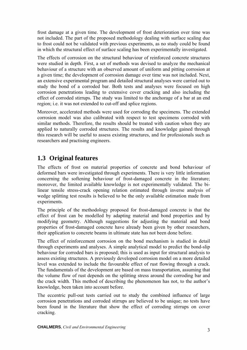
experimental study presented in Paper I, concrete cylinders with two levels of frost damage corresponding to approximately 25% and 50% reduction in compressive strength were tested in compression; see Figure 3(a). It was observed that the ascending branch of the stress-strain relation is affected by a change of the stiffness. This is believed to be caused by the randomly oriented cracks in the concrete due to the damage before the specimens were subjected to loading. Consequently, the loading started with a low stiffness before the cracks had closed, after which the loading continued on a stiffer concrete, see Ueda et al. (2009). However, the stiffness never fully recovered and a permanent stiffness loss was observed, Paper I.
Compressive strength, fccd (MPa)
0 10 20 30 40 50 60
Ten
sile
str
engt
h, f ct
d (M
Pa)
0
2
4
6EuroCode 2CEB-FIP Model Code 1990Undamaged (Fagerlund et al. 1994)Damaged (Fagerlund et al. 1994)Regression
2.1)(027.0 dcc
dct ff
(a)
Compressive strength, fccd (MPa)
0 10 20 30 40 50 60
Ten
sile
str
engt
h, f ct
d (M
Pa)
0
2
4
6CEB-FIP Model Code 1990Undamaged (Hassanzadeh and Fagerlund, 2006)Damaged (Hassanzadeh and Fagerlund, 2006)Undamaged (Shang and Song, 2006)Damaged (Shang and Song, 2006)Undamaged (Paper I)Damaged (Paper I)Regression
2.1)(027.0 dcc
dct ff
(b)
Figure 2. Compressive strength versus tensile strength of frost-damaged concrete from (a) Fagerlund et al. (1994) and (b) three other experimental investigations, (Paper II).
The tensile strength of the frost-damaged concrete was investigated using wedge splitting tests by the author, see Paper I, and splitting tensile tests by other researchers, see Fagerlund et al. (1994), and Shang and Song (2006). A slightly larger effect of

CHALMERS, Civil and Environmental Engineering 9
frost damage on the tensile strength than on the compressive strength has been reported; this can also be seen in Figure 2. However, there is very little information about the softening behaviour of the frost-damaged concrete in tension. This is particularly important because of the direct application of such a relation in numerical analyses. In Paper I, a bi-linear relation, between tensile stress, σct, and crack opening, w, of the frost-damaged concrete, was estimated by using inverse analysis of wedge splitting test results; see Figure 3(b). The tests were performed on cylinder specimens of 100 × 100 mm damaged at two levels equivalent to 25% and 50% reduction in compressive strength. It was found that the fracture energy and the critical crack opening, corresponding to zero tensile stress, was significantly increased by the evolution of damage. A relatively large increase in fracture energy, from 130 Nm/m2 up to approximately 170 Nm/m2, was also reported by Hassanzadeh and Fagerlund (2006). This can be explained by the observations made with the optical measurement system on a wedge splitting test, see Paper I. It was seen that more than one dominant crack and several finer cracks were initiated and propagated for frost-damaged concrete. Therefore, higher energy needed to be dissipated to fully fracture a wedge splitting specimen. To the best knowledge of the author, the bi-linear σct-w relation, given in Paper I, is the only data available in the literature which can be used for non-linear finite element analysis of frost-damaged concrete.
2.4 Effects of frost on bond behaviour Since freezing of concrete affects its strength by internal frost damage and the integrity of the concrete cover by surface scaling, it is expected that the bond properties of concrete are also influenced. Haddad and Numayr (2007) observed that freezing and thawing action caused a significant reduction in bond strength that can be as high as 55%, as well as an increase in free end slip at failure. Fagerlund et al. (1994) suggested lower and upper bound values for the reduction of the bond strength equal to 30% and 70%. The effect of frost damage on bond properties under monotonic and cyclic loading was investigated by Shih et al. (1988). They observed that under monotonic and cyclic loading the bond strength decreased as the number of freezing cycles increased. A linear relationship between the bond strength and the frost-damage, quantified with a relative dynamic elastic modulus, has been suggested by Petersen et al. (2007) and Ji et al. (2008). It was found that when the concrete cover is affected by only a small amount of damage, there is a reduction of the slip values at the maximum bond stress. For more severe frost-damage, an increase in the slip values at the maximum bond stress was observed, see Petersen et al. (2007).
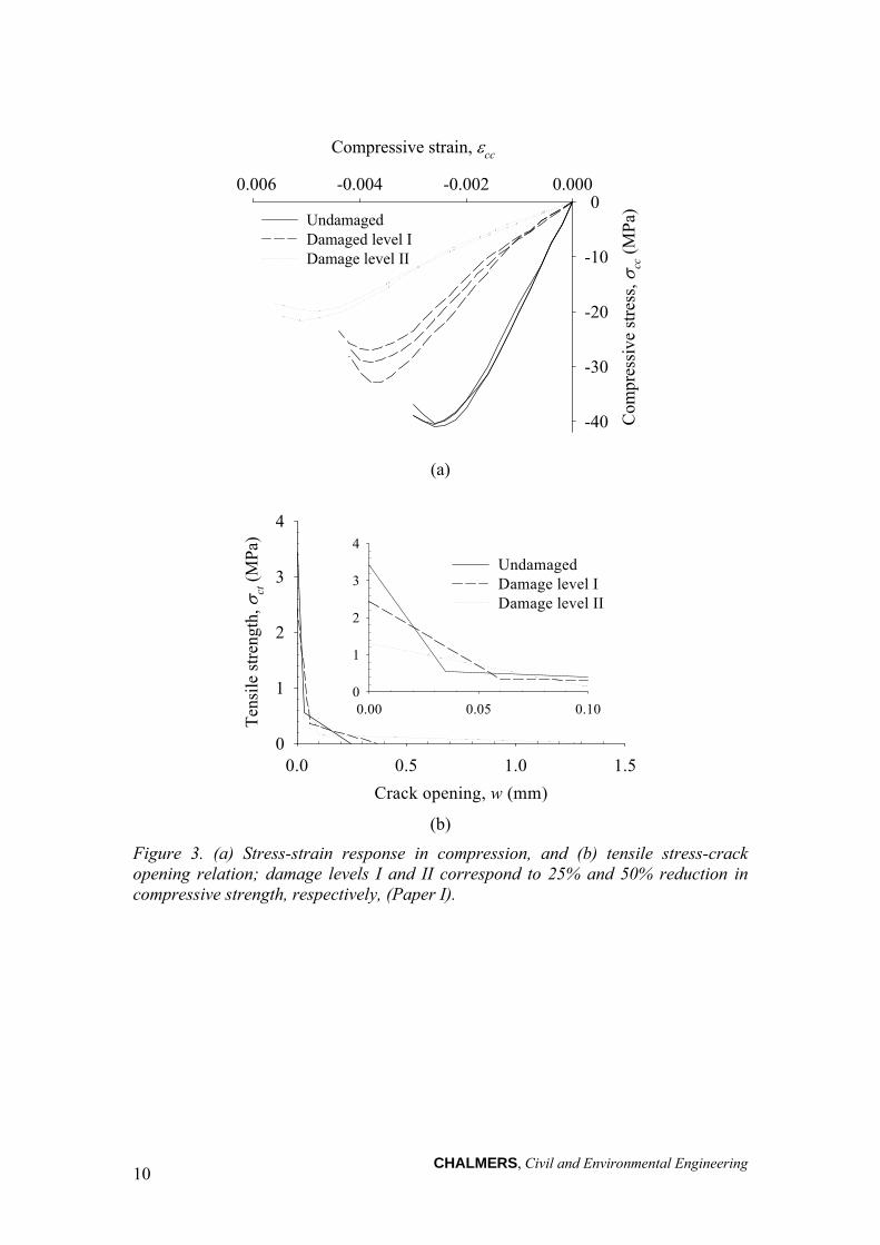
The bond-slip response for two levels of frost damage corresponding to 25% and 50% reduction in compressive strength was investigated with pull-out tests on cylinders, see Figure 4. The damage levels were also characterized by the relative dynamic modulus of elasticity, see Paper I. All tests resulted in pull-out failure at steel stresses below the yield strength, and the failure mode was characterized by shear sliding along the gross perimeter of the rebar. It was observed that the bond capacity was reduced by 14% and 50% for the two levels of damage shown in Figure 4. The stiffness of the ascending branch of the bond-slip response decreased and the slip at the maximum force slightly increased with frost damage, for details see Paper I.
CHALMERS, Civil and Environmental Engineering 10
Compressive strain, cc
0.006 -0.004 -0.002 0.000
Com
pres
sive
str
ess,
cc
(M
Pa)
-40
-30
-20
-10
0UndamagedDamaged level IDamage level II
(a)
Crack opening, w (mm)
0.0 0.5 1.0 1.5
Ten
sile
str
engt
h,
ct (
MP
a)
0
1
2
3
4
0.00 0.05 0.100
1
2
3
4
UndamagedDamage level IDamage level II
(b)
Figure 3. (a) Stress-strain response in compression, and (b) tensile stress-crack opening relation; damage levels I and II correspond to 25% and 50% reduction in compressive strength, respectively, (Paper I).
CHALMERS, Civil and Environmental Engineering 11
0
5
10
15
20
0
20
40
60
510
1520
Bon
d st
ress
(M
Pa)
Compressiv
e stre
ngth (MPa)
Slip (mm)
UndamagedDamage level IDamage level II
Figure 4. Bond-slip response for frost-damaged concrete; damage levels I and II correspond to 25% and 50% reduction in compressive strength, respectively.
2.5 Mechanical behaviour of frost-damaged concrete structures
Depending on the type of damage, internal frost or surface scaling, the load-carrying capacity of a damaged structure is reduced in two ways. Surface scaling causes loss of concrete area, influencing the concrete cover and cross-section; however, the remaining material is assumed to be unaffected, see Wiberg (1993). Hence, anchorage, moment and shear capacities will be reduced. Internal frost damage reduces concrete compressive and tensile strengths, elastic modulus and bond capacity, see Paper I, Fagerlund et al. (2001), Petersen et al. (2007), and Penttala (2002). The change in material and bond properties of frost-damaged concrete will influence the moment, shear and anchorage capacities of a damaged structure. However, these properties are influenced to varying degrees; usually, the shear capacity will be reduced more than the bending capacity. The principal effects of frost damage on the load-carrying capacity of concrete structures are illustrated in Figure 5.
Experimental results reported in Paper I and in the literature, see Fagerlund et al. (1994), Suzuki et al. (2007), and Petersen (2003), showed that the elastic modulus of concrete is significantly reduced by frost. In the serviceability limit state, this influences stiffness and deflection of the structure. For frost-damaged concrete columns, as for beams in flexure, surface scaling changes the concrete cover and, thereby, the concrete cross-section and the slenderness ratio. The possible buckling of damaged columns can be checked by a new slenderness ratio which may mean that a short column is classified as a slender column. The effect of internal frost damage on concrete columns can similarly be taken into account by adapting the material properties and geometry of concrete to recalculate the residual load-carrying capacity, see Fagerlund et al. (2001).

CHALMERS, Civil and Environmental Engineering 12
Figure 5. Principal effects of frost damage on load-carrying capacity, stiffness and force redistribution of a concrete element.
2.6 Modelling the effects of frost on the structural level In Paper II, a methodology to quantify damage caused by the freezing of reinforced concrete structures, in terms of the mechanical behaviour and load-carrying capacity of damaged structures, was introduced. Based on the previous research and the tests presented in Paper I, suggestions were made how to account for the changes in material and bond properties of frost-damaged concrete. The proposed methodology was used to model the behaviour of concrete beams affected by internal frost damage, see Hassanzadeh and Fagerlund (2006). The numerical modelling, presented in Paper II, was done using plane-stress analysis. In the following, a short description of these analyses, together with an example of beam-element analysis carried out on the same beams, is presented.
2.6.1 Plane-stress analysis
Frost-damaged beams tested by Hassanzadeh and Fagerlund (2006) were modelled using four-node quadrilateral plane stress solid elements for the concrete, Figure 6.
Frost
Internal damage Surface scaling
Elastic modulus
Compressive strength
Load-carrying capacity
Anchorage capacity
Shear capacity
Moment capacity
Concrete cross-section
Stiffness and force redistribution
Tensile strength

CHALMERS, Civil and Environmental Engineering 13
X
Y
Z
The concrete was modelled with a constitutive model based on non-linear fracture mechanics using a smeared rotating crack approach, see DIANA (2009). The crack band width was assumed to be equal to the element size; this was later verified to be a good approximation of the localization zone in the analyses. In the analysis of the reference beams, the tensile response of concrete was taken into account according to the model by Hordijk (1991). For the frost-damaged beams, the bi-linear tensile stress-crack opening relation, given in Paper II, for damaged concrete with a 50% reduction in compressive strength was used. This was an acceptable assumption, as the reported compressive strength of the damaged beams indicated approximately 53% reduction compared with that of the reference beams, see Hassanzadeh and Fagerlund (2006). For the behaviour of concrete in compression, the stress-strain curve according to Thorenfeldt et al. (1987) was used for the reference beams. The same relation was adapted according to the proposed methodology in Paper II and used in the analysis of the damaged beams.
The longitudinal reinforcement was modelled by two-node truss elements. Interaction between the reinforcement and the concrete was modelled with a bond-slip relation. Interface elements, describing the bond-slip behaviour in terms of a relation between the tractions and the relative displacements, were used across the reinforcement and the concrete interface. The analytical bond-slip relation for confined concrete under the “good bond conditions” given in CEB-FIP (1993) was assumed for the reference beams. The same relation was adapted according to the proposed modifications in Paper II and used to analyse the damaged beams. The stirrups were embedded in the concrete elements, corresponding to a perfect bond between the stirrups and concrete.
Figure 6. Overall view of the finite element mesh used for plane-stress analysis of a beam affected by frost damage, (Paper II).
2.6.2 Beam-element analysis
The same frost-damaged beams were modelled using beam-element analysis. The concrete was modelled by beam elements and the longitudinal reinforcement was modelled as embedded reinforcement, see Figure 7. The same material properties for concrete and reinforcements as in the plane-stress analysis were used in these analyses. The beam elements used can model only a constant shear stiffness; they do not describe shear failure in concrete beams. Therefore, stirrups were not included in these analyses.
Longitudinal reinforcement with bond-slip
Embedded stirrups
4-node quadrilateral plane stress
50 mm
50 m
m

CHALMERS, Civil and Environmental Engineering 14
X
Y
Z
Figure 7. Overall view of the finite element mesh used for beam-element analysis of a beam affected by frost damage.
The results from plane-stress and beam-element analyses of one type of reference and damaged beams are presented in Figure 8. The beam had tightly spaced stirrups and was moderately reinforced in the tension zone, meaning that the reference beam was expected to fail in bending due to either yielding of reinforcement or crushing of concrete. Both types of analyses showed that the reference beam reached yielding of the tensile reinforcement and failed shortly after due to concrete crushing in the compression zone, which led to a progressive loss of ductility. This agrees with the observations from the experiment. However, the shear effect which results in reduced stiffness could not be described with the beam-element analysis. This explains the underestimation of the deformation at the peak load.
Due to extensive deterioration of concrete, the failure of the damaged beam in the experiment was caused only by crushing of concrete in the compression zone. The stiffness reduction of the frost-damaged beam was relatively well estimated by both analyses. The load and deformation at failure in the plane-stress analysis were in better agreement with the experiment than those of the beam-element analysis. The capacity and deformation of the damaged beam were overestimated by beam-element analysis. Generally, the simplified assumptions usually made in beam-element analysis, such as embedded reinforcement and disregarding the effect of stirrups, lead to less accurate modelling the effects of frost damage at the structural level.
Deformation at midspan, (mm)
0 10 20 30 40 50
Loa
d, F
(kN
)
0
100
200
300
ExperimentPlane-stress analysisBeam-element analysis
Figure 8. Load-deformation for the frost-damaged beam from the plane-stress analysis and the beam-element analysis.
Longitudinal reinforcementwith full interaction
3-node beamelement
283 mm
500 m
m
250 mm

CHALMERS, Civil and Environmental Engineering 15
3 Overview of Corroded Reinforced Concrete Structures
3.1 Background Corrosion of steel reinforcement is one of the most common causes of deterioration in reinforced concrete structures. It affects the safety of a concrete structure. Many existing structures show significant corrosion damage, mainly because they were not durable enough or appropriate maintenance measures had not been taken. Among other environmental impacts, carbonation-induced and chloride-induced corrosion of the reinforcement causes most of the failures in concrete structures. Chloride-induced corrosion is more important for structures exposed to a chloride-containing environment, such as bridges treated with deicing salt in winter, marine concrete structures exposed to sea-water and concrete composed of salt contaminated aggregates. During recent years, much research on the durability aspects of reinforced concrete has been carried out, and lifetime design and assessment based on probabilistic approaches have been developed, see Duracrete (2000).
The corrosion process transforms steel reinforcement into rust, leading to (a) area reduction and ductility change of the reinforcement bars, and (b) volume expansion that generates splitting stresses in the concrete, which may crack and spall the concrete cover; this can affect the bond between reinforcement and concrete. The ductility of a corroded bar depends on exposure environments, i.e. carbonation or chlorides. Practical models to estimate the residual ductility of corroded reinforcement have been suggested in the literature, see Cairns et al. (2005) and Du et al. (2005a).
The effect of corrosion on the bond of corroded bars has been studied by many researchers; for a state-of-the-art see fib (2000). For an overview, including many of the recent references, see Lundgren (2007) and Sæther (2010). Some researchers, e.g. Lee et al. (2002) and Bhargava et al. (2008), have proposed relations for bond capacity versus corrosion level, based on experiments. Others, such as Coronelli (2002) and Wang and Liu (2006), have proposed analytical models for calculating the bond strength. Berra et al. (2003) and Lundgren (2005a) have used detailed finite element modelling to investigate the bond mechanism for corroded bars in concrete. However, this type of detailed three-dimensional modelling of the region around all of the reinforcement bars is impractical for the analysis of complete structures. Therefore, it would be valuable to have a simple bond-slip relation for corroded reinforcement, which can be used for structural analysis in assessment of existing structures; this is the focus of the current chapter. More detail structural analyses and discussions are given in Chapters 4 and 5.
A simple model that provides one-dimensional bond-slip relations for corroded reinforcement was reported in Paper III. Thereafter, a methodology to analyze the mechanical behaviour and the remaining load-carrying capacity of corroded reinforced concrete structures was introduced in Paper IV. The methodology takes into account the effects of both uniform and pitting corrosion, as a change of the material and bond properties, as well as the geometry of the concrete, in order to evaluate the load-carrying capacity of corroded structures. The temporal and spatial variability of uniform and pitting corrosion is not included. The methodology can be used for prediction of the mechanical behaviour of a structure with a measured amount of uniform and pitting corrosion at a given time.

CHALMERS, Civil and Environmental Engineering 16
3.2 Uniform and pitting corrosion A high alkalinity concrete environment, with a pH above 12, forms a passive layer around the reinforcement, which significantly protects the bar from corrosion attack. The corrosion is not initiated as long as the passive layer is sustained. Two processes, carbonation of concrete and chloride attack, may destroy the protection layer. Depending on the type of deterioration process, corrosion of reinforcement may take different forms, ranging from a very widespread to a very local damage, known as uniform and pitting corrosion, respectively; see Böhni (2005) and Broomfield (2003).
When there is uniform or pitting corrosion of a steel bar, the effective reinforcement area is either evenly or locally reduced. The reduction of reinforcement area, or diameter, is most accurately obtained by direct measurements. For a corroded structure with cover spalling, the remaining bar diameter can be measured on the exposed bars after removal of the rust layer. For less corroded structures where the cover has not yet spalled off, small parts of the cover could be removed at non-critical locations, and afterwards repaired. An alternative to direct measurement is to estimate the corrosion penetration based on corrosion rate and time of corrosion initiation, see Luping and Utgenannt (2007) and Meria et al. (2007). Then the reduction of the effective reinforcement diameter due to uniform corrosion is calculated:
x20
(2)
where is the remaining effective diameter of the reinforcement, 0 is the original diameter, and x is the corrosion penetration.
The residual cross-sectional area of locally corroded reinforcement was first estimated with the experimentally verified assumption that the maximum penetration of pitting corrosion is about four to eight times the average corrosion penetration of uniform corrosion, see Gonzalez et al. (1996). Measurements on lightly corroded reinforcement by Cairns et al. (2005) showed that the breadth of pits averaged slightly less than twice the depth, which confirms the assumption of circular cross-section of pits. Based on this assumption, the cross-section loss at a pit increases approximately in proportion to the square of its depth. In this thesis and Paper IV, a pit configuration proposed by Val and Melchers (1997) was used to calculate the residual area of locally corroded reinforcement, Figure 9.
In an experimental investigation carried out by Zhang (2008), the initiation and propagation phases of steel corrosion in a chloride environment were studied. The experimental measurements indicated that pitting corrosion cracks precede uniform corrosion cracks. At the crack initiation stage and the first stage of crack propagation, localized corrosion due to chloride ingression was the predominant corrosion pattern, and the pitting corrosion was the main factor that influenced the cracking process. With the propagation of corrosion cracks, uniform corrosion rapidly developed and gradually became predominant in the second stage of crack propagation.

CHALMERS, Civil and Environmental Engineering 17
pif
pifAA
pifAA
Apit
4
24
2
2
21
2
21
22
11 225.0
pbA
22
22 5.0p
bpA
2
12
p
pb
b
2sin 1
p
b
22sin 2
Figure 9. Pit configuration according to Val and Melchers (1997).
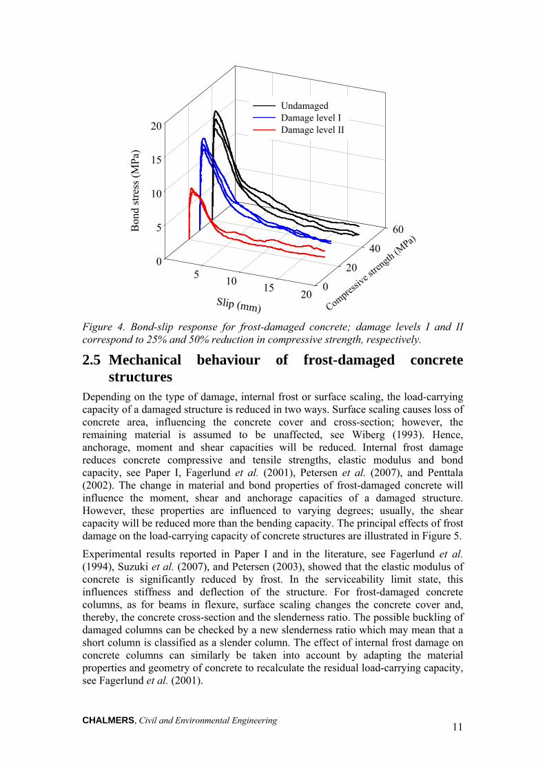
3.3 Properties of corroded steel bars Several studies have investigated the effects of uniform corrosion on the mechanical properties of reinforcement. It has been shown that the yield and ultimate strength ratio and the elastic modulus of steel reinforcement are not significantly affected by corrosion; consequently, the corresponding values for uncorroded reinforcement are still reliable for corroded reinforcement, see Du et al. (2005a and 2005b). The level of reinforcement corrosion does not influence the tensile strength of reinforcement, calculated according to the actual area of cross-section, see Almusallam (2001), Cairns et al. (2005) and Du et al. (2005b). However, the ultimate strain is significantly reduced by uniform corrosion, see Figure 10. Although measured reductions in the ultimate strain and elongation of smaller diameter reinforcements were generally greater than those of larger bar diameter, the observed differences were not more than 5%. Hence, the reduction of the ductility of corroded reinforcement is primarily a function of the amount of corrosion, rather than the bar type and diameter, see Du et al. (2005a).
In a reinforcement bar affected by pitting corrosion, the notch effect induces large and localized strain in the bar. Since the part of the bar affected by pitting corrosion is short, approximately twice the bar diameter, the average strain of the whole bar is less than the local strain at the pit, see Stewart and Al-Harthy (2008). Hence, the bar fails at an average strain lower than the ultimate strain of the uncorroded bar, and the ductility of the entire bar is impaired, see Coronelli and Gambarova (2004) and Du et al. (2005a). Very brittle behaviour is expected when 50% of the cross-section of the reinforcement is locally corroded, Palsson and Mirza (2002). The ultimate strain of locally corroded reinforcement is reduced much more significantly than the yield
b
Ø
p θ2
θ1
CHALMERS, Civil and Environmental Engineering 18
and ultimate strengths calculated according to the original bar area, see Darmawan and Stewart (2007).
(a)
(b)
Figure 10. (a) Variation of ultimate tensile strength, based on the actual bar diameter, for selected degrees of uniform corrosion of a 6 mm diameter steel bar, from Almusallam (2001); (b) Load-elongation curves for a 6 mm diameter steel bar for some degrees of uniform corrosion, from Almusallam (2001).
3.4 Bond between corroded reinforcement and concrete The bond between reinforcement bars and concrete is influenced by several parameters, such as concrete cover, transverse reinforcement, concrete strength, lateral pressure, and the yielding and spacing of the reinforcement bars, see fib (2000). Low bond stresses are resisted mainly by chemical adhesion. Additional bond stresses lead to a failure of the chemical adhesion and cause transverse cracks that radiate from the tip of the ribs, Figure 11. For high loads, the cracks spread radially and the bond stresses extend outwards into the concrete. The stress can be divided into longitudinal bond stress and normal splitting stress. The splitting stresses are resisted by ring stresses in the concrete around the bar, see Figure 12.
0 10 20 30 40 50 60 70 0
100
200
300
400
500
600
Degree of corrosion, percent loss in
Ult
imat
e st
reng
th o
f b
ar [
MP
a]
80
700
800
900
12.6 % 1.5 %
13.9 % 17.8 %
32 % 48 %
75 %
5
10
15
20
2 4 6 8 10 12 14 16 18 20 22
1 %
0
0 %
Elongation [mm]
Loa
d [
kN
]

CHALMERS, Civil and Environmental Engineering 19
Longitudinal splitting crack
Adhesion and friction
Transverse crack
Support of the ribs
N
Figure 11. Cracking caused by bond, modified by Magnusson (2000) from Vandewalle (1992).
The interaction between the reinforcement and the concrete is governed by the splitting stresses and by the friction between the reinforcement and the concrete. Corrosion causes volume expansion leading to splitting stresses that act on the surrounding concrete, thereby reducing the bond properties. The bond strength of corroded bars has been experimentally studied by several researchers; see Al-Sulaimani et al. (1990), Cabrera and Ghoddoussi (1992), Auyeung et al. (2000) and Rodriguez et al. (1995a). For a review of pull-out tests on corroded steel bars, see Sæther (2009a). The main parameters affecting the relative bond strength of corroded steel bars were found to be corrosion penetration, bar position, confinement (concrete cover and transverse reinforcement) and the impressed current density, see Sæther et al. (2007). In the overview presented by Lundgren (2007), the existence of transverse reinforcement and confinement due to the concrete and boundaries were considered to have the greatest influence on the bond. Various models exist to account for the bond behaviour of corroded reinforcement, see Rodriguez et al. (1994), Bhargava et al. (2007) and Chernin et al. (2010). The friction between the reinforcement and the concrete is also influenced by corrosion. In the model by Lundgren (2005b), the volume increase of the corrosion product around a corroded bar has been modelled. Furthermore, it was assumed that corrosion affects the friction between the steel and the concrete.
Splitting crack
Figure 12. Tensile ring stresses in the anchorage zone, from Tepfers (1973).

CHALMERS, Civil and Environmental Engineering 20
An analytical one-dimensional model for the bond-slip response of corroded reinforcement was introduced in Paper III. The proposed model is an extension of the one-dimensional bond-slip model given in CEB-FIP (1993) to include corroded deformed reinforcement. This model is applicable to structural analyses to determine the load-carrying capacity of corroded structures. The formulation of the bond-slip relation is described as a plasticity model; this is equivalent to using a “master curve” and adjusting the slip level, s, to the amount of corrosion, x; see Figure 13. The model was implemented in a computer program, and the results were compared with a 3D model and experimental results. Furthermore, the effect of corrosion on the anchorage length was examined, and comparisons with test results as well as more detailed analyses were made; see Paper III.
Figure 13. The proposed plasticity model is equivalent to using a “master curve” and adjusting the slip level to the amount of corrosion, from Schlune (2006).
3.5 Mechanical behaviour of corroded reinforced concrete structures
The mechanical behaviour of reinforced concrete structures, in terms of load-carrying capacity, as well as stiffness and force redistribution, is affected by the corrosion of reinforcement, see Figure 14. Both uniform and pitting corrosion reduce the reinforcement bar area and ductility, which causes volume expansion. Reduction of the reinforcement bar area leads to decreased shear and moment capacities as well as decreased stiffness of the structure. A change in rebar ductility directly influences the stiffness of the structure, the possibility for force and moment redistribution, and limits the load-carrying capacity of a statically indeterminate structure.
Moreover, volume expansion of reinforcement bars may cause the surrounding concrete to crack and spall off, which decreases the concrete cross-section and concrete cover. On the compressive side of a concrete element, spalling of the cover decreases the internal lever arm, which in turn decreases the bending moment. Furthermore, reduced confinement influences the interaction between the reinforcement and the concrete, which affects the anchorage capacity.
Cracked concrete surrounding corroded reinforcements and stirrups influences the anchorage and shear capacity of a beam. If the concrete in this region has been cracked by corrosion, it has reached its maximum tensile strength. Thus, any further tensile stress induced by mechanical loading contributes to opening larger cracks. Cracked concrete not only affects actual shear and anchorage capacities, but also reduces the load-carrying capacity of a structure in the long-term by giving less
�
skx
Corroded
Uncorroded(master curve)
Uncorroded(shifted curve)

CHALMERS, Civil and Environmental Engineering 21
protection to reinforcement and allowing an aggressive environment direct access to the reinforcement. Moreover, the cracks, depending on their direction, may also change the stiffness, and thereby altering the force distribution in the structure.
In similarity to the effect of surface scaling on a concrete column, described in Section 2.5, the concrete cross-section and slenderness ratio of a concrete column may be changed by corrosion as a result of cover spalling. Therefore, slenderness should be checked for any corroded cross-section, to prevent buckling of a concrete column. This has been studied by some researchers; see Rodriguez et al. (1995b).
Figure 14. Effects of corrosion on load-carrying capacity, stiffness and force redistribution of a concrete element.
Corrosion
Uniform corrosion Pitting corrosion
Rebar ductility
Rebar area Concrete cross-section and cover
Load-carrying capacity
Anchorage capacity
Shear capacity
Moment capacity
Concrete cracking
Volume expansion
Stiffness and force redistribution

CHALMERS, Civil and Environmental Engineering 22
3.6 Modelling the effects of corrosion on the structural level A methodology to analyze the mechanical behaviour and remaining load-carrying capacity of corroded reinforced concrete structures is proposed in Paper IV. The methodology is based on the assumption that the usual method of structural analysis for concrete structures should be applied also to corroded reinforced concrete structures.
As illustrated in Figure 15, it is assumed that the effect of corrosion can be modelled as a change in the geometry and material properties of the concrete, reinforcement and their interface through the following steps.
(1) If corrosion caused the concrete to spall off, the effect on both the concrete cross-section and the cover loss can be taken into account by modifying the geometry used in the analysis. In compression regions where corrosion leads to cracking of concrete, lower strength and stiffness than for the virgin concrete should be assigned to cracked concrete. The behaviour of concrete around corroded stirrups can be simulated by adapting lower tensile strength. The method of adjusting compressive and tensile strength of cracked concrete was suggested in Paper IV.
(2) Reduction of the effective reinforcement area by both uniform and pitting corrosion is the most obvious effect to take into account. The actual area of a uniformly corroded bar can be calculated by assuming that corrosion has penetrated evenly around the bar. However, pitting corrosion affects the reinforcement locally; therefore, measurement or estimation of the pitting configuration is needed to be able to calculate the residual bar area. Finally, the ductility of corroded reinforcement can be calculated using practical models in which the residual ductility is confined to empirical correlations with area loss of the corroded reinforcement.
(3) Corrosion affects the interaction of reinforcement and concrete. Therefore, the bond-slip relationship should be modified accordingly. The modification could be done according to the method proposed in Paper III. This procedure can be applied to models at structural level where the bond-slip between the concrete and reinforcement is modelled by one-dimensional bond-slip relation, for example in plane-stress analysis. For simpler structural analysis models, such as beam-element analysis, where the bond-slip is not directly accounted for in the model, it is proposed that the procedure described in Paper III can be applied to calculate anchorage length. Either the capacity of the reinforcement is then adjusted in the anchorage region, or the anchorage is checked manually.
A relatively similar methodology has been proposed by Sæther (2009b); the two approaches differ in the choices of material models for concrete and reinforcement as well as the bond-slip relation. Moreover, the change in ductility of the reinforcement due to corrosion has not been taken into account.
The methodology presented here was used to study the behaviour of four-point bending tests of corroded beams with a hinge arrangement in the middle tested by Coronelli (1998), and four-point bending tests by Rodriguez et al. (1997). The beams were studied with numerical analyses at the structural level, and hand calculations. Details on the application of the methodology and the results were presented in Paper IV. In the following, a short description of the numerical analyses and hand

CHALMERS, Civil and Environmental Engineering 23
calculations carried out on beams 112 and 113 tested by Rodriguez et al. (1997) is given.
Figure 15. Schematic illustration of the methodology applied on a typical FE mesh of a beam, (Paper IV).
3.6.1 Plane-stress analysis
Two beams tested by Rodriguez et al. (1997) were studied with plane-stress analysis, uncorroded beam 112 and corroded beam 113, see Figure 16. Both beams were under-reinforced and failed in bending due to yielding of reinforcement, see Figure 16. Plane stress solid elements were chosen for the concrete together with a constitutive model based on non-linear fracture mechanics using a smeared rotating crack model, see DIANA (2006). The crack band width was assumed to be equal to the element size; this was later verified to be a good approximation of the localization zone in the analyses. The longitudinal tensile reinforcement was modelled with truss elements; the slip between the main reinforcement and the concrete was included by interface elements, describing the bond-slip behaviour. For corroded beams, the modified bond-slip relation, as explained in Paper III, was employed. The stirrups and compressive reinforcement were embedded in concrete elements by assuming perfect bond between the reinforcement and concrete. The effects of uniform and pitting corrosion were taken into account by modification of the reinforcement area and ductility for tensile and compressive reinforcement as well as stirrups. The FE results were compared with experimental results from Rodriguez et al. (1997).
fc Virgin concrete
Cracked concrete
εco εc,cracked
fc,cracked
CL
Øcorroded
Ø
p θ2
θ1
x 0
2
4
6
8
10
12
14
16
-0.005 -0.003 -0.001 0.001 0.003 0.005 0.007 0.009
Slip [m]
Bo
nd
str
ess
[MP
a]
UncorrodedMoved uncorroded430 μm corroded
ε
Cracked concrete
fct
Virgin concrete
fcc
σcc
σct
εct
εc εcc
b
Ø0

CHALMERS, Civil and Environmental Engineering 24
The uncorroded beams 112 failed in bending due to yielding of tensile reinforcement in the FE analysis and the experiment. The capacity and the failure mode observed in the analysis of corroded beam 113 agreed well with experiment. From the experimental load-displacement curve of this beam, it can be imagined that one tensile reinforcement bar failed in bending first, perhaps due to higher level of corrosion, and the capacity of the beam was reduced to almost half; then the other reinforcement failed. However, in the FE analysis both tensile reinforcements were assumed to reach the yield capacity at the same time. It is concluded that the load-carrying capacity and failure mode of both beams were estimated reasonably well by application of the proposed methodology.
(a)
(b)
Figure 16. (a) Two-dimensional model of the corroded beam 113 and the crack pattern from the plane-stress analysis, and (b) load-displacement of corroded beams tested by Rodriguez et al. (1997), (Paper IV).
3.6.2 Hand calculations
The proposed methodology was intended to be general in the sense that it can be used for different levels of approximation, including full non-linear analyses with three-dimensional solid models, intermediate analyses with shell and frame models, and the
2 Ø 10 Ø 6
2 Ø 8
1150 mm150 mm
200 mm
170 mm
31 mm
200 mmCL
45 mm
30 mm
0
5
10
15
20
25
30
35
40
45
50
0 10 20 30 40 50 60 70
Mid span deflection [mm]
Lo
ad
[kN
]
EXP - Beam 112FEA - Beam 112EXP - Beam 113FEA - Beam 113
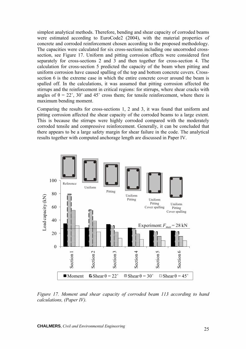
CHALMERS, Civil and Environmental Engineering 25
simplest analytical methods. Therefore, bending and shear capacity of corroded beams were estimated according to EuroCode2 (2004), with the material properties of concrete and corroded reinforcement chosen according to the proposed methodology. The capacities were calculated for six cross-sections including one uncorroded cross-section, see Figure 17. Uniform and pitting corrosion effects were considered first separately for cross-sections 2 and 3 and then together for cross-section 4. The calculation for cross-section 5 predicted the capacity of the beam when pitting and uniform corrosion have caused spalling of the top and bottom concrete covers. Cross-section 6 is the extreme case in which the entire concrete cover around the beam is spalled off. In the calculations, it was assumed that pitting corrosion affected the stirrups and the reinforcement in critical regions: for stirrups, where shear cracks with angles of θ = 22˚, 30˚ and 45˚ cross them; for tensile reinforcement, where there is maximum bending moment.
Comparing the results for cross-sections 1, 2 and 3, it was found that uniform and pitting corrosion affected the shear capacity of the corroded beams to a large extent. This is because the stirrups were highly corroded compared with the moderately corroded tensile and compressive reinforcement. Generally, it can be concluded that there appears to be a large safety margin for shear failure in the code. The analytical results together with computed anchorage length are discussed in Paper IV.
Figure 17. Moment and shear capacity of corroded beam 113 according to hand calculations, (Paper IV).
0
20
40
60
80
100
Sect
ion
1
Sect
ion
2
Sect
ion
3
Sect
ion
4
Sect
ion
5
Sect
ion
6
Loa
d ca
paci
ty (k
N)
Moment Shear θ = 22˚ Shear θ = 30˚ Shear θ = 45˚
Experiment: Fmax = 28 kN
UniformReference
UniformPitting
Pitting
UniformPitting
Cover spalling
UniformPitting
Cover spalling

CHALMERS, Civil and Environmental Engineering 26

CHALMERS, Civil and Environmental Engineering 27
4 Three-dimensional Modelling of Corrosion 4.1 Background Today, structural analyses with beam or shell elements are the most common approach to modelling reinforced concrete structures with the finite element method. In such models the interaction between reinforcement bars and surrounding concrete is usually simplified by assuming full interaction. In more detailed analysis of structural components, two-dimensional solid (continuum) elements are used. The interaction between the reinforcement and concrete can be modelled with a bond-slip relation. In both modelling approaches, the primary effect of corrosion, i.e. area reduction and ductility change of the reinforcement bars, can be taken into account. However, the volume expansion of the corrosion products that generate splitting stresses in the concrete cannot be directly accounted for. The method introduced in Section 3.4 gives an estimation of the bond-slip relation for corroded reinforcement. A disadvantage of using a predefined bond-slip relation as input for analysis is that several conditions must be known in advance, e.g. whether corrosion will lead to spalling of the concrete, or how the corrosion of stirrups may influence the results. Therefore, more detailed modelling of the surrounding concrete and stirrups is required when large corrosion penetrations lead to extensive cover cracking and spalling, and when stirrups are subjected to corrosion.
Three-dimensional finite element modelling has proved to be capable of describing the behaviour of reinforced concrete in a comprehensive way, provided that appropriate constitutive models are adapted. Furthermore, the effect of corrosion on the reinforcement, on the surrounding concrete and on their interaction can be simulated more realistically. Although detailed structural analyses are numerically expensive, they allow for a more accurate description of the corrosion damage at the material and structural levels. Volume expansion of corrosion products, that leads to cover cracking and spalling, significantly influences the confinement conditions and consequently the steel/concrete bond. These effects have been taken into account in bond and corrosion models previously developed by Lundgren (2005a, 2005b). In the bond model, the splitting stresses of the bond action were included; the bond stress depended not only on the slip, but also on the radial deformation between the reinforcement bar and the concrete. Thus, the loss of bond at splitting failure or at yielding of reinforcement could be simulated. The bond model was combined with the corrosion model in which the volume expansion of the corrosion products was simulated. The models, used in three-dimensional modelling of corroded concrete specimens, showed good correspondence with test results for low level corrosion, see Lundgren (2005b), Papers V and VI. However, for high corrosion penetrations, as in Papers V and VI, the corrosion damage obtained in the analysis was considerably greater than that in the tests. The inconsistency observed between numerical analyses and tests for high corrosion penetrations can be explained by the tendency of the corrosion products to penetrate into cracks and to reach the external surface of the cover, see Berra et al. (2003). This may significantly reduce the pressure around the corroded bars, and consequently may reduce the damage to the surrounding concrete. Slow corrosion rates provide sufficient time so that rust penetration may effectively take place. This has been seen in real structures exposed to natural corrosive environments. In Paper VII, the corrosion model was extended to include this phenomenon. The theoretical framework of the bond and corrosion models, as well as
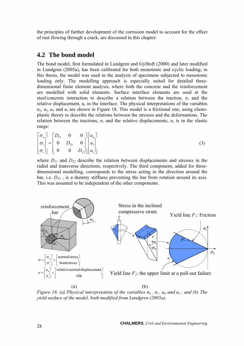
CHALMERS, Civil and Environmental Engineering 28
the principles of further development of the corrosion model to account for the effect of rust flowing through a crack, are discussed in this chapter.
4.2 The bond model The bond model, first formulated in Lundgren and Gylltoft (2000) and later modified in Lundgren (2005a), has been calibrated for both monotonic and cyclic loading; in this thesis, the model was used in the analysis of specimens subjected to monotonic loading only. The modelling approach is especially suited for detailed three-dimensional finite element analysis, where both the concrete and the reinforcement are modelled with solid elements. Surface interface elements are used at the steel/concrete interaction to describe a relation between the traction, σ, and the relative displacement, u, in the interface. The physical interpretations of the variables σn, σt, un and ut are shown in Figure 18. This model is a frictional one, using elasto-plastic theory to describe the relations between the stresses and the deformations. The relation between the tractions, σ, and the relative displacements, u, is in the elastic range:
r
t
n
r
t
n
u
u
u
D
D
D
00
00
00
33
22
11
(3)
where D11 and D22 describe the relation between displacements and stresses in the radial and transverse directions, respectively. The third component, added for three-dimensional modelling, corresponds to the stress acting in the direction around the bar, i.e. D33 , is a dummy stiffness preventing the bar from rotation around its axis. This was assumed to be independent of the other components.
σt
Stress in the inclined compressive struts
μ
-c
Yield line F1: Friction
σn
σt
-σn
c
Yield line F2: the upper limit at a pull-out failure
(a) (b) Figure 18. (a) Physical interpretation of the variables σn , σt , un and ut ; and (b) The yield surface of the model, both modified from Lundgren (2005a).
reinforcement bar
ut σn
σt
un
slip
ntdisplaceme normal relative
stress bond
stress normal
t
n
t
n
u
uu

CHALMERS, Civil and Environmental Engineering 29
The yield lines of the model are described by two yield functions: one explains the friction, F1, assuming that the adhesion is negligible, while the other, F2, describes the upper limit at a pull-out failure determined, from the stress in the inclined compressive struts, which results from the bond action:
0 nt1F ; (4)
0222 nnt cF (5)
More details concerning yield lines, flow rules, and hardening laws have been given in Lundgren (2005a). The model, used in simulation of several pull-out tests, gave results which were in good agreement with the experiments.
4.3 The corrosion model The corrosion model was developed in Lundgren (2002) and further calibrated with several tests in Lundgren (2005b). The effect of corrosion has been modelled as the volume increase of the corrosion products when compared with the virgin steel. The volume of the rust relative to the uncorroded steel, υrs, and the corrosion penetration, x, as a function of the time were used to calculate the free increase of the bar radius, r, i.e. the increase in radius including the corrosion products when the normal stresses were zero. Then the corrosion was modelled by taking time steps. The physical interpretation of the variables in the corrosion model is shown in Figure 19. The free increase of the radius was calculated from:
)2()1( 22 xrxrry rs (6)
The real increase of the radius, uncor, is smaller due to the confinement from the surrounding concrete. This results in a total strain in the rust, εcor:
yx
yuncorcor
(7)
From the normal strain in the rust, corresponding stresses normal to the bars surface were determined. Few studies have been made to describe the mechanical behaviour of rust, see Molina et al. (1993) and Petre-Lazar and Gérard (2000). Experimental results in corrosion cracking tests have been combined with finite element analyses; it has been concluded that rust behaves as a granular material, i.e. its stiffness increases with the stress level, see Lundgren (2005b). This was later verified to be a good estimation of rust behaviour, see Ouglova et al. (2006). In the corrosion model, it was assumed that the mechanical behaviour of the rust at loading could be described as
pcorcorn K (8)
where Kcor represents the stiffness of the corrosion products in the radial direction, εcor is the strain in the rust, and p is an exponent to describe the granular behaviour.

CHALMERS, Civil and Environmental Engineering 30
Initial cross-section
RustCorrosion penetration: x
Volume rust / volume steel: υrs
Free increase of the radius: y
Real increase of the radius: uncor x+y
x
uncor
Uncorroded steel
r
y
Figure 19. Physical interpretations of the variables in the corrosion model, modified from Lundgren (2005b).
It should be noted that the reduction of the bar cross-section due to corrosion is not considered by the corrosion model. This should be done by adapting the yield and ultimate strengths, as well as the Young’s modulus of the steel bar accordingly.
The corrosion model and the bond model can be viewed as two separate layers around a reinforcement bar. However, they are integrated in one interface element to reduce the number of nodes required to model a structure. Due to equilibrium between the two layers, the traction, σ, is the same in the bond and in the corrosion layers. The deformations are related as:
nbondncorn uuu (9)
nbondt uu , 0cortu (10)
where the index cor means the corrosion layer, and the index bond means the bond layer. The equations (9) and (10) are solved within the interface element together with the condition for equilibrium using an iterative procedure.
4.4 Further development of the corrosion model The eccentric pull-out tests, given in Papers V and VI, showed that when the first corrosion crack took place, corrosion products started to flow through cracks and reached the outer surface of the concrete. For large corrosion penetrations, when several new cracks initiated and widened, the flow of rust became significant. This decreased the splitting stress around the bar and consequently reduced the damage to the surrounding concrete. The flow of rust not only depended on the number of cracks and crack width but also varied in time. During the time in which the specimens were subjected to corrosion, the flow of corrosion products took place continuously.
In this thesis, a detailed study of the phenomenon involved in the flow of corrosion product through cracks was not a goal. The main concern was to draw attention to the observations made in laboratory tests and to show the consequence of this type of effect by using numerical analysis. Therefore, several simplified assumptions were made on physiochemical properties of rust and the crack through which rust flows. For instance, the physical state of corrosion products may strongly depend on the oxide composition and the relative humidity in the crack. Moreover, the geometry of the crack in which rust flows may also influence the phenomenon. As there is a lack of such information in the literature, it was assumed that rust behaves as a plug

CHALMERS, Civil and Environmental Engineering 31
material. More details concerning this phenomenon and the assumptions are clearly stated in Paper VII.
The previously developed corrosion model, Lundgren (2005b), was extended to include the rust flow effects. The extended model and results from analyses where it is used are presented here; details concerning assumptions and the derivation of equations together with more results are given in Paper VII. It was assumed that the volume flow of rust depends on the corrosion time interval, crack width and the normal stress in the rust layer. The corrosion time and corrosion rate were given as input to the model. Corrosion penetration, x, was determined theoretically based on Faraday’s law according to:
)(85.5 Itx (11)
where x is corrosion penetration in µm; t is corrosion time in year; and I is impressed current in µA/cm2. The crack width, wcr, was computed from the nodal displacements across the crack. The section area of the crack, through which rust flows, was calculated as:
ewA crcr . (12)
where Acr is the section area of the crack, wcr is the crack width and e is the element size along the crack; see Figure 20. The splitting stress, as in the earlier version of the corrosion model, was evaluated from the strain in the rust using equation (8). The total volume flow of rust, V, through a crack is calculated as the summation of the volume flow of rust in time steps (increments), ΔVi, as
k
iiVV
1
(13)
where index i is the time increment number. The volume flow of rust through a crack, within a time increment, Δti , was expressed by:
iicriii
inicrii tAt
VV
AvV
1,
1
1,1,1 )(2
1
(14)
where v is the velocity of the rust flow; σn is the splitting stress according to equation (8); and ρ is the density of rust. With respect to the volume flow of rust, the free increase of radius of the corroded bar was given from geometry by:
e
Vxrxrry rsext
)2)(1( 22
(15)
where yext is the free increase of the radius due to the remaining rust around the corroded bar, r is the original bar radius and υrs is the volume of the rust relative to the uncorroded steel. Thereafter, the strain in the rust, εcor, is calculated similar to that in the original model using equation (7). The deformation in the interface layer, divided between the bond layer and the corrosion layer, is computed by solving equations (9) and (10) together with the condition for equilibrium using an iterative procedure. Details concerning assumptions and derivation of equations are given in Paper VII.

CHALMERS, Civil and Environmental Engineering 32
(a) (b)
Figure 20. (a) Physical interpretations of the variables in the extended corrosion model; and (b) section area of the crack through which rust flows, (Paper VII).
The original and extended corrosion models were used to analyse a small part of the eccentric pull-out specimens, see Figure 21; the tests are described in Section 5.4. The geometry studied had a dimension of 120 × 120 × 10 mm and included an eccentric bar of 20 mm in diameter. Both the concrete and reinforcement were modelled with three-dimensional pentahedron solid elements with an approximate side length of 10 mm. For the concrete in compression and tension, the models given by Thorenfeldt et al. (1991) and Hordijk (1987) were adopted, respectively. Three corrosion rates of 1, 100 and 500 µA/cm2 were used in the analyses with the extended corrosion model. Details about the analyses are given in Paper VII.
The analysis using the original model could only be carried out to a corrosion weight loss of 2.6 %. This level of corrosion corresponded to extensive cover cracking. For any larger corrosion penetration, severe damage of concrete resulted in numerical instability in the analysis. The numerical instability can be seen as an indication of loss of confinement from the surrounding concrete, eventually leading to cover spalling. However, the analyses with the extended model could be continued with larger corrosion penetrations. In these analyses, numerical instability did not occur until there were corrosion weight losses of 7.5%, 5.6% and 4.7%, when the corrosion rates were 1, 100 and 500 µA/cm2, respectively. This indicates that when wide cracks developed, the favourable effect of rust flowing through cracks became significant; this considerably decreased the splitting stress and, consequently, the damage to the surrounding concrete.
The results from both the original and extended corrosion models, in terms of free increase of corrosion products versus corrosion penetration, are compared in Figure 22 (a). It should be noted that, for the original model, the same results are obtained regardless of the corrosion rate; i.e. a given corrosion level caused the same free increase of rust regardless of the time. On the other hand, the corrosion rate does influence the results for the extended model. It was observed that both models gave similar results before initiation of the first crack which took place at about 1.0% corrosion weight loss. For larger corrosion penetrations, the free increase of rust in the analyses with the extended model was smaller than with the original model. This difference in the free increase of rust in the corrosion models increased rapidly for larger corrosion penetrations. This was expected because the volume flow of rust depends on both time and corrosion penetration. The comparison of the crack width,
r
x
y
wcr
yext
e
c
c
2r
crackedelement
Ad2
d1
d3
d4
aaaaaaaaaaaaaaaaaaaaaaaaaaaaaaaaaaaaaaaaaaaaaaaaaaaaaaaaaaaaaaaaaaaaaaaaaaaaaaaaaaaaaaaaaaaaaaaaaaaaaaaaaaaaaaaaaaaaaaaaaaaaaaaaaaaaaaaaaaaaaaa
aaaaaaaaaaaaaaaaaaaaaaaaaaaaaaaaaaaaaaaaaaaaaaaaaaaaaaaaaaaaaaaaaaaaaaaaaaaaaaaaaaaaaaaaaaaaaaaaaaaaaaaaaaaaaaaaaaaaaaaaaaaaaaaaaaaaaaaaaaaaaaaaaaaaaaaaaaaaaaaaaaaaaaaa
A1
A2
� � 2/)()( 4321 ddddwcr ����
ewAAA crcr ���� 21
e
y-y ex
t

CHALMERS, Civil and Environmental Engineering 33
Figure 22 (b), and crack pattern, Figure 23, shows that the extended model exhibited more corrosion cracks with smaller crack openings. It was also found that the corrosion rate significantly influenced the results. In the analysis with a low corrosion rate of 1 µA/cm2, the crack widths became large that all of the rust produced after about 3% corrosion weight loss flowed through the cracks and did not lead to further increase of splitting stress around the bar.
Figure 21. Geometry and FE model of a small part of the eccentric pull-out specimens, (Paper VII).
The effect of rust flow may also partially explain the spurious deterioration observed in specimens subjected to a high rate of corrosion, see Saifullah and Clark (1994), and Yuan et al. (2007). The time to reach a given corrosion level is considerably shortened for a high corrosion rate; thus, the flow of rust through cracks does not effectively take place. This is an important phenomenon which may significantly affect the experiments and numerical analyses dealing with high corrosion attacks. The extended model is described and discussed in more detail in Paper VII. The model was also used in the analysis of the eccentric pull-out tests; the results are given in Section 5.5 and Paper VII.
10 mm
10 mm
10 mm
120
30 mm 20 mm 70 mm

CHALMERS, Civil and Environmental Engineering 34
Corrosion weight loss (%)
0 1 2 3 4 5
Fre
e in
crea
se o
f th
e ra
dius
, y (m
)
0
50
100
150
Original modelExtended model
I = 500 A/cm2
I = 100 A/cm2
I = 1 A/cm2
(a)
Corrosion weight loss (%)
0 1 2 3 4 5
Cra
ck w
idth
, wcr
(m
m)
0.0
0.1
0.2
0.3
Original modelExtended model
I = 500 A/cm2
I = 100 A/cm2
I = 1 A/cm2
(b)
Figure 22. Numerical results in terms of (a) free increase of corrosion products and (b) crack width, versus corrosion penetration, (Paper VII).

CHALMERS, Civil and Environmental Engineering 35
Ori
gina
l cor
rosi
on m
odel
weight loss 1.0% weight loss 1.6% weight loss 2.6%
Ext
ende
d co
rros
ion
mod
el
weight loss 1.0% weight loss 1.6% weight loss 5.6%
Figure 23. Crack pattern in terms of the maximum tensile strains from numerical analyses with the original corrosion models, and from the extended corrosion models, at a corrosion rate of 100 µA/cm2, (Paper VII).
0.1E-20.9E-30.8E-30.7E-30.6E-30.5E-30.4E-30.3E-30.2E-30.1E-30
0.1E-20.9E-30.8E-30.7E-30.6E-30.5E-30.4E-30.3E-30.2E-30.1E-30

CHALMERS, Civil and Environmental Engineering 36

CHALMERS, Civil and Environmental Engineering 37
5 Cracking and Bond Deterioration due to Corrosion
5.1 Background Many existing concrete structures, for example bridges, piers and parking garages, show significant corrosion; in the presence of high levels of corrosion it is not uncommon that cover cracking, spalling and delamination have occurred, Figure 24. The consequent reduction of bond strength can well be a major problem for the performance of structures in the service and ultimate states, see Val (2007), Zhang (2008), Vidal et al. (2007), Tachibana et al. (1990), Coronelli and Gambarova (2004), Rodriguez et al. (1995a), and Rodriguez et al. (1995b). The study of concrete cracking due to corrosion during the service life is necessary to assess the durability of the structure over time. In particular, crack width can be an indicator of structural distress, see Vidal et al. (2004). In the ultimate limit state, the loss of bond of the main reinforcement in anchorage regions affects the shear strength and anchorage capacity of beams, see Regan and Kennedy Reid (2009), Higgins and Farrow III (2006), Rodriguez et al. (1995b), and Regan and Kennedy Reid (2004).
The effect of corrosion attacks on bond strength has been studied by several researchers, see Almusallam et al. (1996), Cabrera and Ghoddoussi (1992), Clark and Saifullah (1993), Saifullah and Clark (1994), Lee et al. (2002), and fib (2000). Earlier research by the author has identified some of the uncertainties in the information available today, see Zandi Hanjari (2008a). Previous research on the corrosion cracking and bond of corroded reinforcement has been mainly concerned with the corrosion of the main reinforcement of specimens without transverse steel, see Liu (1996), Liu and Weyers (1998), Molina et al. (1993), and Andrade et al. (1993). Very few researchers have studied and compared the corrosion induced cracking of test specimens with and without stirrups, see Alonso et al. (1998). To the knowledge of the author, the effect of corroded stirrups on bond strength has not previously been tested with pull-out tests. A rather common approach in modelling the effect of the corroded stirrups is to take into account the loss of the cross-sectional area; this does not account for the volume expansion of rust around the corroded stirrups, which may lead to cover cracking. Field investigations and laboratory tests have shown that cover delamination is more probable in areas with corroded stirrups, particularly when the stirrups are closely spaced, see Higgins and Farrow III (2006).
Another uncertainty in the available information is the remaining anchorage capacity in structures with severely corroded reinforcement, especially where extensive cracking has taken place or the cover has spalled off. This has been investigated in a few studies. Regan and Kennedy Reid (2009) have studied a similar situation by testing beams, cast without concrete cover, in which bars were either flush with the concrete surface or exposed to mid-barrel. A reduction of the bond strength up to 90% was observed for the bars exposed to mid-barrel; however, the volume expansion of rust and the effect of corroded stirrups were not taken into account, see Regan and Kennedy Reid (2009). Tests, carried out on highly corroded beams with over 20% bar weight loss, have shown that relatively high residual load-carrying capacity was reached when corroded beams failed in bending, see Azad et al. (2007), and Zhang (2008). However, the impact of severe corrosion on the anchorage capacity of deformed bars has not been widely studied.

CHALMERS, Civil and Environmental Engineering 38
Figure 24. Delamination and corrosion of main bars and stirrups, Skurubron, Sweden (photo by Magnus Lindqvist).
In this chapter and Papers V, VI and VII, the two uncertainties outlined above are addressed. The effect of corroded stirrups and severe corrosion leading to extensive cover cracking and spalling was investigated through the study of test results found in the literature and numerical analysis. Thereafter, eccentric pull-out tests were conducted to study the influence of large corrosion penetrations and corroded stirrups on cracking and bond deterioration; these are described in Papers V and VI. The original and extended corrosion models described in Chapter 4 were used in analyses of the eccentric pull-out tests, and the results are compared with experiments in Papers V, VI and VII.
5.2 Effects of corroded stirrups In an experimental program carried out by Higgins and Farrow III (2006), the shear capacity of beams with corroded stirrups was studied. An electrochemical method was used to produce corrosion in stirrups; corrosion of the flexural reinforcement was prevented. Extensive cracking, partial delamination and staining, were observed for sectional losses of stirrups of 12%, 20% and 40%. These authors showed that when stirrups were subjected to corrosion, spacing of the stirrups governed the extent of damage to the concrete cover. In regions with tightly spaced stirrups, the cover cracks from neighbouring stirrups interacted and caused larger areas of spalling and delamination. When stirrups were widely spaced, the damage to the concrete cover was more localized. It has also been shown that the capacity of the beams was reduced by up to 50% when the stirrups were highly corroded.
The effect of corrosion in stirrups was studied through numerical analyses. A thin section of a beam, similar to that tested by Cabrera and Ghoddoussi (1992), was chosen for the study, Figure 25. It should be noted that the aim was not to study the global behaviour of the beam; the main concern was to investigate the influence of corroded stirrups on the bond behaviour. The stirrup was modelled with three-dimensional solid elements, which enabled modelling of the corrosion of stirrups in the analyses. The analyses were carried out with both corroded and uncorroded stirrup for comparison; the main bar at the bottom of the cross-section was corroded in all

CHALMERS, Civil and Environmental Engineering 39
analyses except in the reference analysis. To compare different modelling alternatives, the stirrups were also simulated as embedded reinforcement (without corrosion). The three types of analyses and the boundary conditions are shown in Figure 26. All of the cases were studied using non-linear finite element analysis in the FE program Diana. The analyses were carried out in two phases. In the first phase, corrosion attack was applied in time steps as expansion of the corrosion products using the original corrosion model, see Section 4.3. In the second phase, the bottom bar was pulled out using imposed displacement. An incremental static analysis was made using a Newton-Raphson iterative scheme to solve the non-linear equilibrium equations.
Figure 25. Section of the beam studied; dimensions are in mm.
(a) embedded stirrup (b) 3D uncorroded stirrup (c) 3D corroded stirrup (d) Figure 26. Three types of analysis with: (a) embedded stirrup; (b) 3D uncorroded stirrup; and (c) 3D corroded stirrup. Boundary conditions and the direction of the imposed deformation on the main bar are also shown in (c) and (d). The black parts of the bars and stirrup were subjected to corrosion.
The studied section had a thickness of 20 mm. Due to symmetry, half of the cross-section was modelled with an approximate element size of 5 mm. The boundary
160
125
12
10
8
25
20
10
12
CHALMERS, Civil and Environmental Engineering 40
conditions at the symmetry line, the bottom main bar, and the side of the section are shown in Figure 26 (c). The Euler-Bernoulli beam assumption, i.e. plane sections remain plane and normal to the axis of the beam, were applied on both cross-sectional planes of the beam. Eight-node solid elements were used for the concrete and longitudinal reinforcements. The same types of elements were used to model the stirrup when it was simulated in three-dimensions. It should be noted that interaction between the stirrup and the main bar was not geometrically modelled in detail; in the model the direct interaction between the bars was avoided by using a small distance between them occupied by concrete elements. The interaction between the 3D bars and concrete was modelled with surface interface elements. For concrete, a constitutive model based on non-linear fracture mechanics, with a smeared rotating crack model based on total strain, was applied, see DIANA (2009). The crack band width was assumed to be equal to the element size; this was later verified to be a good approximation of the localization zone in the analyses. For the concrete in compression and tension, the models by Thorenfeldt et al. (1987) and Hordijk (1991) were adopted, respectively. The reinforcing steel was modelled according to an isotropic plastic model with the Von Mises yield criterion.
The longitudinal bar on the bottom was subjected to corrosion; the bar on the top was not corroded, Figure 26. In the analysis with 3D corroded stirrups, the bottom leg of the stirrup was subjected to corrosion, while the vertical leg was corroded halfway up to the concrete cross-section. These choices were made in order to study a situation which is commonly seen in real structures, i.e. corrosion attack from one direction. A uniform corrosion was imposed, i.e. all of the bar’s circumference was subjected to the same corrosion penetration. In each analysis, the same corrosion penetration was imposed on the main bar and stirrup.
The results, in terms of average bond stress versus free-end slip, are compared for uncorroded (reference) and corroded sections with 5, 10, 20 and 30 µm corrosion penetrations, Figure 27. The analysis of reference section was carried out when the stirrup was modelled with three-dimensional elements as well as with embedded reinforcement. Both analyses gave very similar results; in Figure 27, the result for reference section is presented from analysis with 3D stirrups. The analyses could not be carried out for larger corrosion penetrations, as the corrosion damage resulted in extensive cracking, which made the analysis numerically unstable. Such a situation, in which several corrosion cracks penetrated the concrete cover and reached the surface, may correspond to cover spalling; this is further discussed in the following section. The results from the analyses with embedded stirrup and a 3D uncorroded stirrup differed slightly. This was partially due to the bending stiffness of the 3D stirrup; embedded reinforcement had stiffness along the bar only. Moreover, slip between the stirrup and concrete was allowed in the analysis with a 3D stirrup, while embedded reinforcement corresponded to full interaction between the stirrup bar and the concrete; this is another reason for the difference observed in the results.
All three types of analyses showed rather similar bond strength for low corrosion penetrations, i.e. a slight increase in bond strength before corrosion cracking. The difference in the results became larger with increased corrosion level. The analysis with an embedded stirrup showed the highest bond strength, while the one with a 3D corroded stirrup showed the lowest bond strength. The first crack took place in the analysis with 3D corroded stirrups at about 25 µm corrosion penetration; thereafter, the bond strength suddenly decreased, Figure 27 (d). Neither of the other two analyses showed any corrosion cracking before 55 µm corrosion penetration. Therefore, it was

CHALMERS, Civil and Environmental Engineering 41
concluded that the corrosion of stirrups made cover cracking take place earlier and caused a considerably larger reduction in bond strength. Moreover, detailed modelling of stirrups was required to include the effects of corroded stirrups in a realistic way. However, such analyses are computationally expensive and may not be possible in the modelling of large scale tests such as beams.
Free-end slip (mm)
0.00 0.05 0.10 0.15 0.20
Ave
rage
bon
d st
ress
(M
Pa)
0
3
6
9
12ReferenceEmbedded stirrup3D non-corroded stirrup3D corroded stirrup
(a) 5 µm corrosion penetration (b) 10 µm corrosion penetration
Free-end slip (mm)
0.00 0.05 0.10 0.15 0.20
Ave
rage
bon
d st
ress
(M
Pa)
0
3
6
9
12ReferenceEmbedded stirrup3D non-corroded stirrup3D corroded stirrup
(c) 20 µm corrosion penetration (d) 30 µm corrosion penetration
Figure 27. Average bond stress versus free-end slip for (a) - (d) 5 - 30 µm corrosion penetrations, respectively.
5.3 Modelling of corrosion leading to cover spalling The analyses of the section with corroded stirrup described in Section 5.2 had problems with numerical instability for large corrosion penetrations. Numerical problems appeared when corrosion cracks penetrated the concrete cover and extended to the surface; this may resemble a cover spalling situation. Thus, wide corrosion cracks caused numerical instability. To avoid large crack opening, two-node spring elements were placed on the bottom and side covers, see Figure 28 (a). A physical interpretation of this measure is to prevent the cracked cover from falling off; in reality, the corrosion cracking along the bar varies, and uncracked parts contribute to prevent the cracked parts from falling off. A low stiffness of 1 GPa was chosen for the
Free-end slip (mm)
0.00 0.05 0.10 0.15 0.20A
vera
ge b
ond
stre
ss (
MP
a)
0
3
6
9
12ReferenceEmbedded stirrup3D non-corroded stirrup3D corroded stirrup
Free-end slip (mm)
0.00 0.05 0.10 0.15 0.20
Ave
rage
bon
d st
ress
(M
Pa)
0
3
6
9
12ReferenceEmbedded stirrup3D non-corroded stirrup3D corroded stirrup

CHALMERS, Civil and Environmental Engineering 42
spring elements; this is about 30 times less than the elastic modulus of a normal strength concrete. The analyses given in Section 5.2 were carried out again with spring elements included in the FE model. The influence of this on the results was negligible; the effect on the bond strength was less than 0.5% and no change in the crack pattern was observed. However, spring elements prevented the cracks from becoming wide; thus, the analysis could be conducted for larger corrosion penetrations.
The average bond stress versus free-end slip from the analysis in which the stirrups were simulated with three-dimensional elements is shown in Figure 29. Significant bond deterioration was observed for 100 µm corrosion penetration; this corresponded to about 60% reduction in bond strength. In this analysis, the stirrup yielded at the angle of the corner when the bar was pulled out. This was because of large stresses in the stirrup across the crack and cross-section loss of stirrup due to high corrosion. Yielding of the stirrup did not occur in any other of the analysis.
The cracks from the analyses with 100 µm corrosion penetration, Figure 28 (b, c and d), showed distinctly different patterns. The analysis with embedded stirrups showed bottom cover spalling between the main bars. However, the analysis with 3D uncorroded stirrups showed complete corner cover spalling. Corrosion of the stirrup led to a full delamination plane across the bottom cover. Two of the crack patterns (c and d) are frequently seen in real structures. Observations made in the laboratory test by Higgins and Farrow III (2006) confirm that when tightly spaced stirrups are corroding, a delamination plane is more likely to take place.

CHALMERS, Civil and Environmental Engineering 43
(a) FE mesh with spring elements (b) analysis with an embedded stirrup
(c) analysis with a 3D uncorroded stirrup (d) analysis with a 3D corroded stirrup
Figure 28. (a) FE mesh with spring elements; and (b, c and d) crack patterns in terms of the maximum tensile strains from numerical analyses of sections with 100 µm corrosion penetration.

CHALMERS, Civil and Environmental Engineering 44
Free-end slip (mm)
0.00 0.02 0.04 0.06 0.08
Ave
rage
bon
d st
ress
(M
Pa)
0
3
6
9
5 m10 m
20 m
30 m
40 m
100 m
Figure 29. Average bond stress versus free-end slip from the analyses with a 3D corroded stirrup for different corrosion penetrations.
5.4 Eccentric pull-out tests A research program comprising both the study of corrosion cracking and bond strength deterioration was undertaken. The aim was to better understand the effects of large corrosion attacks and of corroding stirrups on cracking and bond strength in anchorage regions. Details about the tests are given in the appended Papers V and VI as well as a test report, see Zandi Hanjari and Coronelli (2010). Paper V deals with corrosion-induced cracking and Paper VI presents results on bond strength deterioration. Some aspects of the experimental program and some of the results are summarized.
The eccentric pull-out specimens had the shape of a beam-end after inclined shear cracking, see Figure 30. The behaviour of the eccentric pull-out tests shares some similarities and dissimilarities with a beam-end region. For example, similar to a beam-end region, the inclined strut is carried on both the anchored bar and the support region. However, in the test specimens, the main bars were not in contact with the concrete over the support. The effect of support pressure and the anchorage of the bar over the support are therefore not the same as they are at the end of a beam.

CHALMERS, Civil and Environmental Engineering 45
(a) beam-end (b) specimen type A (c) specimen types B and C
Figure 30. Schematic illustration of: (a) beam-end region; (b) specimen type A; and (c) specimen types B and C, (Papers V and VI).
The influences of the location of the anchored bar, i.e. middle or corner placement; the presence or absence of transverse reinforcement; the corrosion level of longitudinal reinforcement and the corrosion of transverse reinforcement were studied. The specimens were of three types in relation to the reinforcement arrangement and corrosion: specimens without stirrups, where the main bars were corroded (type A); specimens with stirrups where the main bars were corroded and the stirrups were protected by insulating tape (type B); and specimens with stirrups where the main bars and stirrups were corroded (type C). All of the specimens were subjected to accelerated corrosion, with an average current density of 100 µA/cm2, for three time spans that caused a rebar weight loss up to approximately 20% in the main bars and 35% in the stirrups. All of the specimens showed longitudinal cracks along the main bars for relatively low corrosion levels. The corrosion level at first cracking was about 0.6% - 1.0% corrosion weight loss; the cracks widened with increased corrosion levels. Crack patterns formed depended on the presence or absence of stirrups and whether the stirrups were corroded, see Figure 31.

CHALMERS, Civil and Environmental Engineering 46
Crack nr. 1 2 3 4 5 6 7 8 9 10
Width (mm) 1.4 1.0 1.0 0.9 0.5 0.5 0.2 0.4 0.6 0.4
(a) specimen type A
Crack nr. 1 2 3 4 5 6 7 8 9 10 11 12
Width (mm) 0.50 0.30 0.35 0.20 0.4 0.5 0.9 0.4 0.4 0.3 0.4 0.4
(b) specimen type B
Crack nr. 1 2 3 4 5 6 7 8 9 10 11 12 13
Width (mm) 0.15 0.20 0.10 0.30 0.20 0.15 0.15 0.05 0.10 0.3 0.25 0.25 0.1
(b) specimen type C
Figure 31. Typical examples of crack patterns and crack widths at the corrosion level of 2 - 10% bar weight loss, (Paper V). The black colour indicates rust stains.

CHALMERS, Civil and Environmental Engineering 47
An overview of the pull-out test results in comparison with the reduction in residual bond strength for corroded reinforcement, given by CEB-FIP Model Code 2010 is shown in Figure 32. The bond strengths of the eccentric pull-out specimens were normalized once with respect to that of the reference specimens (a) and (b), and with respect to that of the middle bar in reference specimens (c) and (d); this was done separately for the specimens with and without stirrups. In general, the average bond strength of specimens with stirrups was less influenced by corrosion than that of the specimens without stirrups. This shows the importance of the confinement provided by stirrups after cover cracking. The largest bond deterioration was seen in the type A specimens on the corner bars; this was because of the absence of stirrups and a smaller portion of surrounding concrete available to a corner bar compared with that of a middle bar. The least bond deterioration was measured in type B specimens on the corner bars. This is believed to be caused by the effective interaction between the stirrups and the main bars at the angle of the corner. It can be concluded that, for large corrosion penetrations that cause extensive cover cracking, stirrups play an important role in terms of being the main source of confinement. Moreover, the deterioration trend proposed by CEB-FIP Model Code 2010, when compared with the test results, remained on the safe side.
Corrosion weight loss (%)
0 5 10 15 20
Nor
mal
ized
bon
d st
reng
th
0
25
50
75
100
Corner barMiddle bar
Corrosion weight loss (%)
0 5 10 15 20
Nor
mal
ized
bon
d st
reng
th
0
25
50
75
100
Corner barMiddle bar
(a) specimens without stirrups (b) specimens with stirrups
Corrosion weight loss (%)
0 5 10 15 20
Nor
mal
ized
bon
d st
reng
th
0
25
50
75
100
Model Code 2010: upper limitModel Code 2010: lower limitCorner barMiddle bar
Corrosion weight loss (%)
0 5 10 15 20
Nor
mal
ized
bon
d st
reng
th
0
25
50
75
100
Model Code 2010: upper limitModel Code 2010: lower limitCorner barMiddle bar
(c) specimens without stirrups (d) specimens with stirrups
Figure 32. Overview of the test results in terms of bond strength, (a) and (b) normalized with respect to that of the reference specimens; (c) and (d) normalized with respect to that of the middle bar in the reference specimens, versus corrosion attack, (Paper VI).

CHALMERS, Civil and Environmental Engineering 48
5.5 Three-dimensional modelling of eccentric pull-out tests The behaviour of the eccentric pull-out specimens in corrosion phase and pull-out tests was studied through three-dimensional non-linear finite element analyses. The numerical results are given in Papers V and VI using the original corrosion model and in Paper VII using the extended corrosion model.
The modelling technique and material models were similar to those explained in Section 5.2. Analyses with the extended corrosion model were conducted at a corrosion rate of 100 µA/cm2, which is similar to that in the experiments.
The numerical analyses with the original corrosion model showed good correspondence with the tests results, which confirmed the failure modes and crack pattern obtained in the tests. The analyses also gave reasonably good results in terms of bond stress versus slip for the specimens with small corrosion attacks of up to about 1%. A small difference between tests and analyses concerns the slip for the uncorroded specimens; the analyses resulted in weaker behaviour with slightly larger slip values for the ascending branch than the test results. This behaviour can be seen also in earlier analyses with the bond model used, see Lundgren (2005a) and (2005b). The main reason for this difference is that, when the bond model was calibrated, the primary focus was the ultimate limit state, with anchorage failure. The bond model needs to be better calibrated for small slip values.
Moreover, it should be noted that, in the analysis with the original corrosion model, for corrosion attacks larger than about 1%, the deterioration obtained was considerably greater than that in the tests. Therefore, the analyses of large corrosion penetrations could not be made, as the damage level resulted in extensive cover cracking which caused the analysis to become numerically unstable. The maximum corrosion levels achieved in the analyses were 1.4, 1.7 and 0.3% for specimens of types A, B and C, respectively. The second phase of the analyses simulating the pull-out tests was conducted with these corrosion attacks. The difference in the corrosion levels that caused extensive cover cracking and termination of the analysis, for the three types of specimens, was related to the amount of confinement, i.e. the presence or absence of stirrups and whether or not they were corroded.
In the analyses with the extended corrosion model, for which the effect of rust flowing through cracks was included, the extensive cover cracking was reached at significantly larger corrosion penetrations compared with that in the analyses with the original corrosion model. Corrosion-induced crack patterns in terms of the maximum tensile strains from numerical analysis with the original and extended corrosion models are compared in Figure 33. In general, the crack pattern has changed slightly when the effect of rust flowing through the cracks was included, i.e. more cracks of smaller width were seen in the analyses with the extended corrosion model. This corresponds better to the measurements on the specimens.
The results from numerical analysis with the extended corrosion model, in terms of average bond stress versus free-end slip as well as crack patterns, are presented in Figures 34 and 35. The behaviour of the specimens without stirrups, type A, was relatively well predicted, both in the corner bar test and the middle bar test. The agreement was less good when the specimens had stirrups and especially when the stirrups were corroded. Generally, less bond capacity for the corroded bars was obtained in the analysis than that measured in the experiments. This is further discussed in Paper VII.

CHALMERS, Civil and Environmental Engineering 49
It should be noted that time-dependent effects, creep and shrinkage, were not included in the analyses. These effects may increase the deflection of a structure under service loads during corrosion stage. Phased analyses of service life cycle with the time-dependent effects, carried out by Sæther (2010), showed a significant increase in the deflection of beams during corrosion stage. This has also been shown through beam tests subjected to a low rate corrosion process during service life, see Zhang (2008). In the tests presented in this thesis, time-dependent effects were of less importance as artificial corrosion process significantly shortened the corrosion time. Moreover, the specimens were not subjected to any external load prior to mechanical testing.
Type A Type B Type C
Ori
gina
l cor
rosi
on m
odel
1.4% corrosion
(no stirrups)
1.7% corrosion
(main bars only)
0.3% corrosion weight loss
(main bars and stirrups)
Ext
ende
d co
rros
ion
mod
el
8.7% corrosion corner bar
7.9% corrosion middle bar
(no stirrups)
15.7% corrosion corner bar
14.0% corrosion middle bar
(main bars only)
15.5% corrosion corner bar
7.0% corrosion middle bar
17.0% corrosion all the stirrups
Figure 33. Corrosion-induced crack patterns in terms of the maximum tensile strains from numerical analyses of the eccentric pull-out specimens. The weight loss of the reinforcement is indicated below each figure, (Paper VII).
0.1E-20.9E-30.8E-30.7E-30.6E-30.5E-30.4E-30.3E-30.2E-30.1E-30
0.1E-20.9E-30.8E-30.7E-30.6E-30.5E-30.4E-30.3E-30.2E-30.1E-30

CHALMERS, Civil and Environmental Engineering 50
Free-end slip, s (mm)
0 1 2 3
Ave
rage
bon
d st
ress
, b
(MP
a)
0
2
4
6
8
10
Test: referenceTest: left barTest: right barFEA: referenceFEA: left barFEA: right bar
[%]
6.47.98.7
Free-end slip, s (mm)
0 1 2 3
Ave
rage
bon
d st
ress
, b
(MP
a)
0
2
4
6
8
10
Test: referenceTest: middle barFEA: referenceFEA: middle bar in the left sectionFEA: middle bar in the right section
[%]
3.99.06.5
(a) type A - corner bar (b) type A - middle bar
(c) type B - corner bar (d) type B - middle bar
(e) type C - corner bar (f) type C - middle bar
Figure 34. Average bond stress versus free-end slip from numerical analyses and experiments. Pull-out was done for the corrosion level indicated in the small figures. The figure legend given for (a) is valid for (c) and (e), and the figure legend given for (b) is valid for (d) and (f), (Paper VII).
Free-end slip, s (mm)
0 1 2 3
Ave
rage
bon
d st
ress
, b
(MP
a)
0
2
4
6
8
10
15.7 14.0 9.2
[%]
Free-end slip, s (mm)
0 1 2 3
Ave
rage
bon
d st
ress
, b
(MP
a)
0
2
4
6
8
10
0.72.10.0
[%]
Free-end slip, s (mm)
0 1 2 3
Ave
rage
bon
d st
ress
, b
(MP
a)
0
2
4
6
8
10
[%]
17.017.0
17.017.0
15.5 7.0 9.8
Free-end slip, s (mm)
0 1 2 3
Ave
rage
bon
d st
ress
, b
(MP
a)
0
2
4
6
8
10
[%]33.9
26.624.0
13.2 7.0 16.7 11.1

CHALMERS, Civil and Environmental Engineering 51
0.1E-20.9E-30.8E-30.7E-30.6E-30.5E-30.4E-30.3E-30.2E-30.1E-30
0.1E-20.9E-30.8E-30.7E-30.6E-30.5E-30.4E-30.3E-30.2E-30.1E-30
Type A Type B
Ref
eren
ce s
peci
men
s su
bjec
ted
to p
ull-
out
Reference Reference
Cor
rode
d sp
ecim
ens
subj
ecte
d to
pul
l-ou
t
8.7% corrosion corner bar
7.9% corrosion middle bar
15.7% corrosion corner bar
14.0% corrosion middle bar
Figure 35. Crack patterns, in terms of the maximum tensile strains, of specimens subjected to pull-out. The weight loss of the reinforcement is indicated below each figure. The black parts of the main bars were subjected to corrosion.

CHALMERS, Civil and Environmental Engineering 52

CHALMERS, Civil and Environmental Engineering 53
6 Conclusions 6.1 General conclusions The aim of this work is to improve the understanding of the structural behaviour of deteriorated concrete structures with special attention to the bond between deformed bars and concrete. The research program comprised the study of the two most common causes of deterioration in concrete structures, i.e. freezing of concrete and corrosion of reinforcement. In the research approach, laboratory experiments and non-linear finite element simulations were combined to study the structural effect of the deterioration. The most important conclusions drawn from the work carried out on each type of deterioration are summarized in this chapter.
The effects of freezing on the material properties of concrete and the bond behaviour of reinforcement bars in concrete were investigated through experiments. Inverse analyses were used to determine the stress-crack opening (σct-w) relation for frost-damaged concrete. Based on these experiments and other tests found in the literature, a set of methods was introduced to predict the mechanical behaviour of reinforced concrete structures with a measured amount of frost damage. The methodology was intended to be general in the sense that it can be used for different levels of approximation, ranging from full non-linear analyses with three-dimensional solid models to the simplest analytical methods. This methodology was applied to frost-damaged beams using non-linear finite element analysis at the structural level. The main conclusions of this work are listed here.
Frost-damage changes the internal structure of concrete by initiating micro and macrocracks; this was demonstrated through microscopic technique and analysis of thin sections. Such a change in the internal structure of concrete affects its compressive strength; it also lengthens the travel time of an ultrasonic wave passing through the damaged concrete. For this reason, changes in the compressive strength of concrete and in the relative dynamic modulus of elasticity were found to be suitable indicators of frost damage.
Frost-damaged concrete under compression exhibits a considerably lower initial elastic modulus, a relatively larger strain at the peak stress and a more ductile response in the post-peak behaviour, when compared with undamaged concrete. This leads to a significant change in the stress-strain response. The analyses carried out on frost-damaged beams showed a great influence of such a change in stress-strain response when predicting the failure modes and failure loads.
In the study of the behaviour of frost-damaged concrete in tension, it was found that the fracture energy and critical crack opening, corresponding to zero tensile stress, were significantly increased by the evolution of frost damage. The suggested bi-linear σct-w relation, estimated by using inverse analysis carried out on wedge splitting test results, can be used as input in finite element analysis of frost-damaged concrete.
The tests carried out in this thesis as well as other research works showed a major influence of frost on the bond strength. The bond stress-slip relation proposed by CEB-FIB Model Code 90 was extended to incorporate frost effects. It should be noted that very few studies have investigated the bond behaviour of frost-damaged concrete through pull-out tests. Bond tests

CHALMERS, Civil and Environmental Engineering 54
evaluating a variety of anchorage situations, such as middle or corner anchored bar, are needed. Therefore, the available models should be updated accordingly.
The knowledge gained through material and bond tests was implemented in a methodology which can be used in the assessment of frost-damaged structures. Application of the methodology in the analysis of frost-damage beams indicated that the changes in failure mode and, to a significant extent, the effect on failure load caused by internal frost damage can be predicted by using the proposed methodology. However, an uncertainty was the extension and distribution of the damaged region over the cross-section, which affected the prediction of the failure load and deformation.
The effects of corrosion damage on the structural behaviour of reinforced concrete structures were studied more in detail. First, the bond-slip model given in Model Code 1990 was extended to include corroded reinforcement, and a method was devised to analyze the mechanical behaviour of a structure with an observed amount of uniform and pitting corrosion at a given time. The method was applied to analysis of corroded beams using non-linear finite element simulation at the structural level. The effects of large corrosion penetrations and of corroded stirrups were found to be important uncertainties in the available knowledge, as well as in the proposed method. Next, an extensive experimental program and detailed three-dimensional structural analyses were conducted to study the bond of a corroded bar. The tests and analyses were focused on both large corrosion attacks leading to extensive cover cracking and the effect of corroded stirrups. A previously developed corrosion model was extended to include the effects of rust flowing through cracks. The extended model was applied in the detailed three-dimensional structural analyses of the eccentric pull-out tests. The most important conclusions of this work are listed here.
The analytical bond-slip relation of corroded reinforcement, the maximum bond stress, and the anchorage length needed to withstand the yield force obtained from the suggested model all show a qualitatively reasonable response when compared with the experiments; i.e. the results are consistent with the physical behaviour. It should be noted, however, that for large corrosion penetrations and without any, or with only a small amount of, transverse reinforcement, the calculated anchorage length might not be on the safe side. Thus, if the concrete cover has spalled off completely, it may not be safe to use the model to estimate the required anchorage lengths.
The main uncertainties in the analysis of corroded reinforced beams were: (a) the bond properties when extensive cover cracking or spalling has taken place, and when stirrups have been subjected to corrosion; (b) the ductility of corroded reinforcement; and (c) the temporal and spatial variability of pitting corrosion. It was found that taking into account only pitting corrosion or uniform corrosion may lead to overestimation of the residual load-carrying capacity of a structure. For better estimation, both of the corrosion effects have to be taken into account.
The experimental program aimed to evaluate the bond strength when corrosion had already caused extensive cover cracking and spalling; this condition is encountered in highly corroded real structures. Complete cover spalling did not occur in the tests, though a partial propagation of the phenomenon was observed. When crack patterns were monitored and documented, it was found

CHALMERS, Civil and Environmental Engineering 55
that the specimens with corroded stirrups showed more cracks and large quantities of rust flowing out of the cracks.
Bond strength measured in the eccentric pull-out tests showed the significant influence of the stirrups, position of the bar tested and corrosion level. Less bond capacity was observed for a bar positioned in a corner; this became even more important in the absence of stirrups. Moreover, a rather complex failure mode was observed in specimens with stirrups. This was a result of the effective interaction between stirrups and main bars at the angle of the corner. The specimens with corroded stirrups showed more extensive cracking, but comparatively little bond deterioration. It was concluded that significant bond deterioration starts only when the level of stirrup corrosion is very high.
The three-dimensional FE analysis of test specimens, with the original corrosion model, showed good correspondence with the test results, which confirmed the corrosion-induced crack pattern, first cracking caused by the corrosion, and failure modes in the pull-out test. The analyses also gave reasonably good results in terms of bond stress versus slip for the specimens with small corrosion attacks, up to about 1%. For larger corrosion attacks, the deterioration obtained in the analysis was considerably more than that in the tests. This is believed to be caused by the tendency of the corrosion products to penetrate into the cracks and reach the external surface of the cover. This significantly decreases the pressure around the corroded bars; consequently it reduces the damage to the surrounding concrete. The original corrosion model used in the numerical analysis did not include this phenomenon.
The original corrosion model was extended to include the phenomenon, that rust flows through the cracks, in a simple and realistic way. Application of the extended corrosion model in the analysis of the eccentric pull-out tests showed a qualitatively reasonable response when compared with experiments, i.e. the model resulted in more corrosion cracks with smaller crack openings, which better corresponded to the measurements on specimens tested.
6.2 Suggestions for future research Previous research on frost-damaged concrete is concerned primarily with the causes and mechanisms of frost deterioration, but relatively little attention has been given to the problem of assessing the load-carrying capacity of frost-damaged concrete structures. Moreover, very few studies were found to investigate the material and bond properties of frost-damaged concrete, in comparison with numerous studies focused on other causes of deterioration, such as corrosion. Further experimental investigations on the effect of frost at the material level, such as compression and tension tests, as well as at the structural level, such as pull-out and beam tests are needed.
Based on the literature study, it was found that the ductility of corroded reinforcement can be calculated using practical models in which the residual ductility is confined to empirical correlations of area loss of the corroded reinforcement. However, the reported correlation factor varies widely. Thus, more research is needed to investigate how the ductility is affected by a variety of aggressive conditions. The temporal and spatial variability of uniform and pitting corrosion also needs to be further investigated.

CHALMERS, Civil and Environmental Engineering 56
Little experimental data is available for the bond behaviour of severely corroded reinforcement with cover spalling. Moreover, the majority of experimental results report the bond properties of reinforcement which was corroded artificially with accelerating methods. Therefore, further experimental investigations of the bond properties of corroded reinforcement exposed to a natural aggressive environment is suggested, especially for structures with severe corrosion.
The anchorage length calculated by the model proposed for the bond-slip relation of corroded reinforcement is uncertain for large corrosion penetrations. The main reason for this is that in the model proposed, the bond capacity of corroded reinforcement can never be lower than the residual bond stress defined in CEB-FIP (1993). Further development of the model based on bond tests with high corrosion levels is required.
Moreover, the extended corrosion model, which takes into account the effect of rust flowing through cracks, needs to be further developed. First, a detailed study of the phenomenon including the physiochemical properties of rust, the crack through which rust flows, and the flow mechanism involved, is suggested. Next, it is proposed to set up tests in which the volume of flowing rust and its dependence on crack width, corrosion rate, elapsed time, and rust composition, for example, can be measured. Such experimental data would be very useful for further verification and calibration of the model.
With the advanced FE program packages, superior post and pre-processors and powerful computers available today, it is believed that three-dimensional non-linear finite element analysis can be used more often in simulations of test specimens. Three-dimensional detailed analyses give comprehensive insights to the problem, provided appropriate models are adapted. Although development of such models has always been a mainstream in research and development, much more research is still needed.
The present study was limited to the evaluation of the load-carrying capacity of a structure with a measured amount of damage at a given time. The development of damage over time is a subject that needs much more research. Above all, the combined effects of corrosion and frost need to be studied.

CHALMERS, Civil and Environmental Engineering 57
7 References American Concrete Institute ACI (2007). Manual of Concrete Practice, American Concrete Institute, Detroit, Michigan.
Al-Sulaimani, G. J., Kaleemullah, M., Basunbul, I. A. and Rasheeduzzafar (1990). Influence of corrosion and cracking on bond behavior and strength of reinforced concrete members. ACI Structural Journal, Vol. 87, No. 2, pp. 220–231.
Almusallam, A. A. (2001). Effect of degree of corrosion on the properties of reinforcing steel bars. Construction and Building Materials, Vol. 15, No 8, 361–368.
Almusallam, A. A., AlGahtani, A. S., Aziz, A. R., Dakhil, F. H. and Rasheeduzzafar (1996). Effect of reinforcement corrosion on flexural behavior of concrete slabs. Journal of Materials in Civil Engineering, Vol. 8, No 3, pp. 123–127.
Alonso, C., Andrade, C., Rodriguez, J. and Diez, J. M. (1998). Factors controlling cracking of concrete affected by reinforcement corrosion. Materials and Structures/Materiaux et Constructions. Vol. 31, No. 211, pp. 435–441.
Andrade, C., Alonso, C., and Molina, F. J. (1993). Cover cracking as a function of bar corrosion.1. Experimental test. Materials and Structures, Vol. 26, No. 162, pp. 453–464.
Auyeung, Y., Balaguru, P. and Chung, L. (2000). Bond behavior of corroded reinforcement bars. ACI Materials Journal, Vol. 97, No. 2, pp. 214–220.
Azad, A. K., Ahmad, S. and Azher, S. A. (2007). Residual strength of corrosion-damaged reinforced concrete beams. ACI Materials Journal, Vol. 104, No. 1, pp. 40–47.
Beaudoin, J. J. and MacInnis, C. (1974). The mechanism of frost damage in hardened cement paste. Cement and Concrete Research, Vol. 4, No. 2, pp. 139–147.
Berra, M., Castellani, A., Coronelli, D., Zanni, S. and Zhang, G. (2003). Steel-concrete bond deterioration due to corrosion: Finite-element analysis for different confinement levels. Magazine of Concrete Research, Vol. 55, No. 3, pp. 237–247.
Bhargava, K., Ghosh, A. K., Mori, Y. and Ramanujam, S. (2007). Models for corrosion-induced bond strength degradation in reinforced concrete. ACI Materials Journal, Vol. 104, No. 6, pp. 594–603.
Bhargava, K., Ghosh, A. K., Mori, Y. and Ramanujam, S. (2008). Suggested empirical models for corrosion-induced bond degradation in reinforced concrete. Journal of Structural Engineering, Vol. 134, No. 2, pp. 221–230.
Broomfield, J. P. (2003). Corrosion of Steel in Concrete, London, England, Taylor & Francis (Chalmers e-Library), 240 pp.
Böhni, H. (2005). Corrosion in Reinforced Concrete Structures, Cambridge, England, Woodhead Publishing Limited, 248 pp.
Cabrera, J. G. and Ghoddoussi, P. (1992). The effect of reinforcement corrosion on the strength of the steel/concrete "bond". Proceedings of the International Conference: Bond in Concrete. Riga, Latvia, 10-11–10-24.
Cairns, J., Plizzari, G. A., Du, Y., Law, D. W. and Franzoni, C. (2005). Mechanical properties of corrosion-damaged reinforcement. ACI Materials Journal, Vol. 102, No. 4, pp. 256–264.

CHALMERS, Civil and Environmental Engineering 58
CEB (1993). CEB-FIP Model Code 1990, Bulletin d'Information 213/214, Lausanne, Switzerland.
CEB (2010). CEB-FIP Model Code 2010 - First complete draft. Bulletin 55, Volume 1, Lausanne, Switzerland.
Chatterji, S. (1999). Aspects of the freezing process in a porous material-water system: Part 1. Freezing and the properties of water and ice. Cement and Concrete Research, Vol. 29, No. 4, pp. 627–630.
Chernin, L., Val, D. V. and Cairns, J. (2010). A new numerical model of the corroded steel-concrete interface. Magazine of Concrete Research, Vol. 62, No. 6, pp. 415–425.
Clark, L. A. and Saifullah, M. (1993). Effect of corrosion on reinforcement bond strength. Proceeding of the 5th International Conference on Structural Faults and Repairs, Edinburgh, pp. 113–119.
Coronelli, D. (1998). Bar Corrosion in Steel-concrete Bond: Material and Structural Effects in R/C. Doctoral thesis, Structural Engineering Department, Politecnico di Milano, Italy, 201 pp.
Coronelli, D. (2002). Corrosion cracking and bond strength modeling for corroded bars in reinforced concrete. ACI Structural Journal, Vol. 99, No. 3, pp. 267–276.
Coronelli, D. and Gambarova, P. (2004). Structural assessment of corroded reinforced concrete beams: Modeling guidelines. Journal of Structural Engineering, Vol. 130, No. 8, pp. 1214–1224.
Darmawan, M. S. and Stewart, M. G. (2007). Effect of pitting corrosion on capacity of prestressing wires. Magazine of Concrete Research, Vol. 59, No. 2, pp. 131–139.
DIANA (2006). DIANA Finite Element Analysis, User's Manual, release 9.1. TNO Building and Construction Research, Delft, Netherlands.
DIANA (2009). DIANA Finite Element Analysis, User's Manual, release 9.3. TNO Building and Construction Research, Delft, Netherlands.
Du, Y. G., Clark, L. A. and Chan, A. H. C. (2005a). Effect of corrosion on ductility of reinforcing bars. Magazine of Concrete Research, Vol. 57, No. 7, pp. 407–419.
Du, Y. G., Clark, L. A. and Chan, A. H. C. (2005b). Residual capacity of corroded reinforcing bars. Magazine of Concrete Research, Vol. 57, No. 3, pp. 135–147.
Duracrete (2000). General Guidelines for Durability Design and Redesign. Probabilistic Performance Based Durability Design of Concrete Structures. Document BE95-1347/R15, The European Union, Brite EuRam III.
EN1992-1-1 (2004). Eurocode 2: Design of Concrete Structures - Part 1: General rules and rules for buildings, CEN European Committee for Standardization, Brussels, 225 pp.
Fagerlund, G. (2004). A Service Life Model for Internal Frost Damage in Concrete. Report No. TVBM - 3119, Division of Building Materials, Lund University, Lund, Sweden.
Fagerlund, G., Janz, M. and Johannesson, B. (1994). Effect of frost damage on the bond between reinforcement and concrete, A contribution to the BRITE/EURAM project BREU-CT92-0591, The Residual Service Life of Concrete Structures, Division of Building Materials, Lund Institute of Technology, Lund, Sweden.

CHALMERS, Civil and Environmental Engineering 59
Fagerlund, G., Somerville, G. and Jeppson, J. (2001). Manual for Assessing Concrete Structures Affected by Frost, EC Innovation Project IN30902I, CONTECVET: A validated user’s manual for assessing the residual service life of concrete structures, Division of Building Materials, Lund Institute of Technology, Lund, Sweden.
International Federation for Structural Concrete (fib) Bulletin 10 (2000). Bond of Reinforcement in Concrete, State-of-art report, Fédération internationale du béton, prepared by Task Group Bond Models, Lausanne, 2000.
Gong, J. X., He, S. Q. and Guo, Y. X. (2005). Influence of freezing and thawing cycles on bond characteristics of steel bar and concrete in salt environment. Dalian Ligong Daxue Xuebao/Journal of Dalian University of Technology, Vol. 45, No. 3, pp. 405–409.
Gonzalez, J. A., Feliu, S., Rodriguez, P., Ramirez, E., Alonso, C. and Andrade, C. (1996). Some questions on the corrosion of steel in concrete - Part I: When, how and how much steel corrodes. Materials and Structures, Vol. 29, No. 185, pp. 40–46.
Gudmundsson, G. and Wallevik, O. (1999). Concrete in an aggressive environment. International RILEM Workshop on Frost Damage in Concrete, Proceeding 25, pp. 87–102.
Haddad, R. H. and Numayr, K. S. (2007). Effect of alkali-silica reaction and freezing and thawing action on concrete-steel bond. Construction and Building Materials, Vol. 21, No. 2, pp. 428–435
Hasan, M., Okuyama, H., Sato, Y. and Ueda, T. (2004). Stress-strain model of concrete damaged by freezing and thawing cycles. Journal of Advanced Concrete Technology, Vol. 2, No. 1, pp. 89–99.
Hasan, M., Ueda, T. and Sato, Y. (2008). Stress-strain relationship of frost-damaged concrete subjected to fatigue loading. Journal of Materials in Civil Engineering, Vol. 20, No. 1, pp. 37–45.
Hassanzadeh, M. and Fagerlund, G. (2006). Residual strength of the frost-damaged reinforced concrete beams. The Proceedings of the III European Conference on Computational Mechanics Solids, Structures and Coupled Problems in Engineering, Lisbon, Portugal.
Higgins, C. and Farrow III, W. C. (2006). Tests of reinforced concrete beams with corrosion-damaged stirrups. ACI Structural Journal, Vol. 103, No. 1, pp. 133–141.
Hordijk, D. A. (1991). Local Approach to Fatigue of Concrete. Doctoral thesis, Delft University of Technology, Delft, Netherlands.
Ji, X., Song, Y. and Liu, Y. (2008). Effect of freeze-thaw cycles on bond strength between steel bars and concrete. Journal Wuhan University of Technology, Materials Science Edition, Vol. 23, No. 4, pp. 584–588.
Kruschwitz, J. and Bluhm, J. (2005). Modeling of ice formation in porous solids with regard to the description of frost damage. Computational Materials Science, Vol. 32, pp. 407–417.
Lee, H.-S., Noguchi, T. and Tomosawa, F. (2002). Evaluation of the bond properties between concrete and reinforcement as a function of the degree of reinforcement corrosion. Cement and Concrete Research, Vol. 32, No. 8, pp. 1313–1318.

CHALMERS, Civil and Environmental Engineering 60
Liu, Y. (1996). Modeling the Time-to-corrosion Cracking of the Cover Concrete in Chloride Contaminated Reinforced Concrete Structures. Doctoral thesis, Department of Civil Engineering, Virginia Polytechnic Institute and State University, Blacksburg, Virginia, 116 pp.
Liu, Y. and Weyers, R. E. (1998). Modeling the time-to-corrosion cracking in chloride contaminated reinforced concrete structures. ACI Materials Journal, Vol. 95, No. 6, pp. 675–681.
Lundgren, K. (2005a). Bond between ribbed bars and concrete. Part 1: Modified model. Magazine of Concrete Research, Vol. 57, No. 7, pp. 371–382.
Lundgren, K. (2005b). Bond between ribbed bars and concrete. Part 2: The effect of corrosion. Magazine of Concrete Research, Vol. 57, No. 7, pp. 383–395.
Lundgren, K. (2007). Effect of corrosion on the bond between steel and concrete: An overview. Magazine of Concrete Research, Vol. 59, No. 6, pp. 447–461.
Lundgren, K. (2002). Modelling the effect of corrosion on bond in reinforced concrete. Magazine of Concrete Research, Vol. 54, No. 3, pp. 165–173.
Lundgren, K. and Gylltoft, K. (2000). A model for the bond between concrete and reinforcement. Magazine of Concrete Research, Vol. 52, No. 1, pp. 53–63.
Luping, T. and Utgenannt, P. (2007). Verification of a rapid technique for corrosion measurement using reinforced concrete slabs after long-term field exposure, International Conference on Concrete Platform, Belfast, pp. 229–238.
Magnusson, J. (2000). Bond and Anchorage of Ribbed Bars in High-Strength Concrete. Doctoral thesis, Division of Concrete Structures, Chalmers University of Technology, Göteborg, Sweden, 299 pp.
Meria, G. R., Andrade, C., Alonso, C. and Borba Jr., J. C. (2007). Chloride penetration into concrete structures in marine atmosphere zone – Influence of environmental characteristics. International RILEM workshop on Integral Service Life Modeling of Concrete Structures, Guimaraes, Portugal.
Mohamed, O. A., Rens, K. L. and Stalnaker, J. J. (2000). Factors affecting resistance of concrete to freezing and thawing damage, Journal of Materials in Civil Engineering, Vol. 12, No. 1, pp. 28–32
Molina, F. J., Alonso, C. and Andrade, C. (1993). Cover cracking as a function of rebar corrosion. 2. Numerical model. Materials and Structures, Vol. 26, No. 163, pp. 532–548.
Ouglova, A., Berthaud, Y., François, M. and Foct, F. (2006). Mechanical properties of an iron oxide formed by corrosion in reinforced concrete structures. Corrosion Science, Vol. 48, No. 12, pp. 3988–4000.
Palsson, R. and Mirza, M. S. (2002). Mechanical response of corroded steel reinforcement of abandoned concrete bridge. ACI Structural Journal, Vol. 99, No. 2, pp. 157–162.
Penttala, V., Al-Neshawy, F. (2002). Stress and strain state of concrete during freezing and thawing cycles. Cement and Concrete Research, Vol. 32, No. 9, pp. 1407–1420.

CHALMERS, Civil and Environmental Engineering 61
Petersen, L. (2003): Einfluss Baustofflicher Schädigungsprozesse auf das Tragverhalten von Stahlbetonbauteilen. Doctoral thesis, Berichte aus dem Institut für Baustoffe, Universität Hannover, Germany.
Petersen, L. and Lohaus, L. (2004). Influence of chemical and physical loads on deteriorational design studies – concrete properties, bond and bending behavior. Proceeding of 2nd International Conference of Lifetime Oriented Design Concepts, Bochum, Germany.
Petersen, L., Lohaus, L. and Polak, M. A. (2007). Influence of freezing-and-thawing damage on behavior of reinforced concrete elements. ACI Materials Journal, Vol. 104, No. 4, pp. 369–378.
Petre-Lazar, I. and Gérard, B. (2000). Mechanical behaviour of corrosion products formed at the steel - concrete interface. Testing and modelling. Proceedings of EM2000, Fourteenth Engineering Mechanics Conference, Austin, Texas, USA.
Powers, T. C. (1945). A working hypothesis for further studies of frost resistance of concrete. Journal of the American Concrete Institute, Vol. 16, No. 4, pp. 245–271.
Regan, P. E. and Kennedy-Reid, I. (2009). Assessment of concrete structures affected by delamination: 1 - Effect of bond loss. Studies and Research - Annual Review of Structural Concrete, Vol. 29, pp. 245–275.
Regan, P. E. and Reid, I. L. K. (2004). Shear strength of RC beams with defective stirrup anchorages. Magazine of Concrete Research, Vol. 56, No. 3, pp. 159–166.
Rodriguez, J., Ortega, L. M. and Casal, J. (1994). Corrosion of reinforcing bars and service life of reinforced concrete structures: Corrosion and bond deterioration. International Conference on Bond Across Borders, Odense, Denmark, Vol. 2, pp. 315–326.
Rodriguez, J., Ortega, L. M. and Casal, J. (1997). Load carrying capacity of concrete structures with corroded reinforcement. Construction and Building Materials, Vol. 11, No. 4, pp. 239–248.
Rodriguez, J., Ortega, L. M. and Casal, J. (1995a). The Residual Service Life of Reinforced Concrete Structures: Relation between corrosion and load bearing capacity of concrete beams. Report BRITE/EURAM PROJECT BREU CT92 0591.
Rodriguez, J., Ortega, L. M. and Casal, J. (1995b). The Residual Service Life of Reinforced Concrete Structures: Relation between Corrosion and Load Bearing Capacity of Concrete Columns. Report BRITE/EURAM PROJECT BREU CT92 0591.
Sæther, I. (2009a). Bond deterioration of corroded steel bars in concrete. Structure and Infrastructure Engineering, First published on: 29 July 2009 (iFirst), DOI: 10.1080/15732470802674836.
Sæther, I. (2009b). Finite element simulation of reinforced concrete beams attacked by corrosion. Nordic Concrete Research, Vol. 39, pp. 15–32.
Sæther, I., Antonsen, A. and Vennesland, Ø. (2007). Effect of impressed anodic current density applied to accelerated corrosion laboratory results. International RILEM Workshop on Integral Service Life Modeling of Concrete Structures, Guimaraes, Portugal, pp. 307–314.

CHALMERS, Civil and Environmental Engineering 62
Sæther, I., Kanstad, T., Øverli, J. A. and Bergström, M. (2010). Phased time-dependent FE analysis of reinforced concrete beams. Magazine of Concrete Research, Vol. 62, No. 8, pp. 543–556.
Sæther, I. (2010). Structural Behaviour of Deteriorated and Retrofitted Concrete Structures. Doctoral thesis, Department of Structural Engineering, Norwegian University of Science and Technology, Trondheim, Norway, 218 pp.
Saifullah, M. and Clark, L. A. (1994). Effect of corrosion rate on the bond strength of corroded reinforcement. Proceedings of International Conference: Corrosion and Corrosion Protection of Steel in Concrete. University of Sheffield, UK, pp. 591–602.
Schlune, H. (2006): Bond of Corroded Reinforcement: Analytical Description of the Bond-slip Response. Master thesis, No. 2006:107, Department of Civil and Environmental Engineering, Chalmers University of Technology, Göteborg, Sweden, 73 pp.
Shang, H. S. and Song, Y. P. (2006). Experimental study of strength and deformation of plain concrete under biaxial compression after freezing and thawing cycles. Cement and Concrete Research, Vol. 36, No. 10, pp. 1857–1864.
Shih, T. S., Lee, G. C. and Chang, K. C. (1988). Effect of freezing cycles on bond strength of concrete. Journal of Structural Engineering, Vol. 114, No. 3, pp. 717–726.
Stewart, M. G. and Al-Harthy, A. (2008). Pitting corrosion and structural reliability of corroding RC structures: Experimental data and probabilistic analysis. Reliability Engineering and System Safety, Vol. 93, No. 3, pp. 373–382.
Sun, W., Zhang, Y. M., Yan, H. D. and Mu, R. (1999). Damage and damage resistance of high strength concrete under the action of load and freeze-thaw cycles. Cement and Concrete Research, Vol. 29, No. 9, pp. 1519–1523.
Suzuki, T. and Ohtsu, M. (2004). Quantitative damage evaluation of structural concrete by a compression test based on AE rate process analysis. Construction and Building Materials, Vol. 18, No. 3, pp. 197–202.
Suzuki, T., Ohtsu, M. and Shigeishi, M. (2007). Relative damage evaluation of concrete in a road bridge by AE rate-process analysis. Materials and Structures, Vol. 40, No. 2, pp. 221–227.
Tachibana, Y., Maeda, K. I., Kajikawa, Y. and Kawamura, M. (1990). Mechanical behavior of RC beams damaged by corrosion of reinforcement. Proceedings of the 3rd International Symposium on Corrosion of Reinforcement in Concrete Construction, UK, pp.178–187.
Tang, L. and Petersson, P. E. (2004). Slab test: Freeze/thaw resistance of concrete – Internal deterioration. Materials and Structures, Vol. 37, No. 274, pp. 754–759.
Tepfers, R. (1973): A Theory of Bond Applied to Overlapped Tensile Reinforcement Splices for Deformed Bars. Doctoral thesis, Division of Concrete Structures, Chalmers University of Technology, Göteborg, Sweden.
Thorenfeldt, E., Tomaszewicz, A. and Jensen, J. J. (1987). Mechanical properties of high-strength concrete and applications in design. Conference on Utilization of High-Strength Concrete. Stavanger, Norway.

CHALMERS, Civil and Environmental Engineering 63
Ueda, T., Hasan, M., Nagai, K., Sato, Y. and Wang, L. (2009). Mesoscale simulation of influence of frost damage on mechanical properties of concrete. Journal of Materials in Civil Engineering, Vol. 21 No. 6, pp. 244–252.
Val, D. V. (2007). Deterioration of strength of RC beams due to corrosion and its influence on beam reliability. Journal of Structural Engineering, Vol. 133, No. 9, pp. 1297–1306.
Val, D. V. and Melchers, R. E. (1997). Reliability of deteriorating RC slab bridges. Journal of Structural Engineering, Vol. 123, No. 12, pp. 1638–1644.
Valenza, J. J. and Scherer, G. W. (2006). Mechanism for salt scaling. Journal of the American Ceramic Society, Vol. 89, No. 4, pp. 1161–1179.
Vandewalle, L. (1992). Theoretical prediction of the ultimate bond strength between a reinforcement bar and concrete. Proceedings of the International Conference: Bond in Concrete. Riga, Latvia, pp. 1-1–1-8
Vidal, T., Castel, A. and François, R. (2004). Analyzing crack width to predict corrosion in reinforced concrete. Cement and Concrete Research, Vol. 34, No. 1, pp. 165–174.
Vidal, T., Castel, A. and François, R. (2007). Corrosion process and structural performance of a 17 year old reinforced concrete beam stored in chloride environment. Cement and Concrete Research, Vol. 37, No. 11, pp. 1551–1561.
Wang, X. and Liu, X. (2006). Bond strength modeling for corroded reinforcements. Construction and Building Materials, Vol. 20, No. 3, pp. 177–186.
Wiberg, U. (1993). Material Characterization and Defect Detection in Concrete by Quantitative Ultrasonics, Doctoral thesis, Institutionen för Byggkonstruktion, Kungl Tekniska Högskolan, Stockholm, 1993, 152 pp.
Yuan, Y., Ji, Y. and Shah, S. P. (2007). Comparison of two accelerated corrosion techniques for concrete structures. ACI Structural Journal, Vol. 104, No. 3, pp. 344–347.
Zandi Hanjari, K. (2008a). Load-Carrying Capacity of Damaged Concrete Structures. Licentiate thesis, Department of Civil and Environmental Engineering, Chalmers University of Technology, Göteborg, Sweden, 98 pp.
Zandi Hanjari, K. (2008b). Material and Bond Properties of Frost-Damaged Concrete. Report No. 2008:10, Department of Civil and Environmental Engineering, Chalmers University of Technology, Göteborg, Sweden.
Zandi Hanjari, K. and Coronelli, D. (2010). Anchorage Capacity of Corroded Reinforcement: Pull-out Tests on Beam-end Specimens. Report No. 2010-06, Department of Civil and Environmental Engineering, Chalmers University of Technology, Göteborg, Sweden, Dipartimento di Ingegneria Strutturale, Politecnico di Milano, Milan, Italy.
Zhang, R. (2008): Analysis of Both Initiation and Propagation Phases of Corrosion in Reinforced Concrete Structures and Their Influence on Service Life. Doctoral thesis, Laboratoire Matériaux et Durabilité des Constructions, Universite de Toulouse, Toulouse, France, 190 pp.

CHALMERS, Civil and Environmental Engineering 64
Zuber, B. and Marchand, J. (2000). Modeling the deterioration of hydrated cement systems exposed to frost action – Part 1: Description of the mathematical model. Cement and Concrete Research, Vol. 30, No. 12, pp. 1929–§1939.


![Analysis of concrete structures deteriorated by alkali ... · Analysis of concrete structures deteriorated by alkali-aggregate ... The Brazilian standard NBR 15577-1 [2], defines](https://img.pdfslide.us/doc/110x75/5c25435409d3f2e82a8b7ad7/analysis-of-concrete-structures-deteriorated-by-alkali-analysis-of-concrete.jpg)