Embed Size (px)
Citation preview

Cite this paper as: Ruiz-Teran AM, Aparicio AC, 2008, Structural behaviour and design criteria of under-deck cable-stayed bridges and combined cable-stayed bridges. Part 2: Multispan bridges, Canadian Journal of Civil Engineering, Vol:35, ISSN:0315-1468, Pages:951-962 [doi:
10.1139/L08-034]
- 1 -
Structural behaviour and design criteria of
Under-deck cable-stayed bridges and Combined cable-stayed bridges.
Multi-span bridges.
A. M. Ruiz-Teran a,1
, A. C. Aparicio b
a Assistant Professor. Department of Civil Engineering and Building. University of Castilla-
La Mancha, Spain.
Academic Visitor at Imperial College London, U.K.
Av. Camilo José Cela s/n 13071. Ciudad Real. Spain
b Professor. Department of Construction Engineering. Technical University of Catalonia.
C. Jordi Girona 1-3. 08034. Barcelona. Spain.
Word count:
Title and address ....................................................................................................................... 71
Abstract and keywords ........................................................................................................... 141
Sections 1-6 .......................................................................................................................... 6271
References .............................................................................................................................. 256
Figures (8x250) ................................................................................................................... 2000
Tables (5x250) ...................................................................................................................... 1250
Total ..................................................................................................................................... 9989
1 Corresponding author: Tel: +34 926295300 (ext. 3277) Fax: +34 926295391
E-mail address: [email protected] or [email protected]

Cite this paper as: Ruiz-Teran AM, Aparicio AC, 2008, Structural behaviour and design criteria of under-deck cable-stayed bridges and combined cable-stayed bridges. Part 2: Multispan bridges, Canadian Journal of Civil Engineering, Vol:35, ISSN:0315-1468, Pages:951-962 [doi:
10.1139/L08-034]
- 2 -
Abstract
This paper deals with the application of under-deck cable-staying systems and combined
cable-staying systems to prestressed concrete road bridges with multiple spans of medium
length. Schemes using under-deck cable-staying systems are not suitable for continuous
bridges, since they are not efficient under traffic live load and only allow for the
compensation of permanent load. However, combined cable-staying systems are very efficient
for continuous bridges and enable the design of very slender decks (1/100 of span) where the
amount of materials used is halved in comparison with conventional schemes without stay
cables. In this paper, the substantial advantages provided by combined cable-staying systems
for continuous bridges (such as high structural efficiency, varied construction possibilities,
both economic and aesthetical benefits, and landscape integration) are set out. Finally, design
criteria are included.
Key words:
under-deck cable-staying; combined cable-staying; cable-stayed bridges; prestressed concrete;
bridges

Cite this paper as: Ruiz-Teran AM, Aparicio AC, 2008, Structural behaviour and design criteria of under-deck cable-stayed bridges and combined cable-stayed bridges. Part 2: Multispan bridges, Canadian Journal of Civil Engineering, Vol:35, ISSN:0315-1468, Pages:951-962 [doi:
10.1139/L08-034]
- 3 -
1. Introduction
Over the last thirty years, more than twenty bridges have been built using under-deck cable-
staying systems (cable-stayed bridges with the stay cables located below the deck) and
combined cable-staying systems (cable-stayed bridges with the stay cables located both
above and below the deck). Some of them are multi-span continuous bridges. For at least nine
continuous bridges, these new types of cable-staying systems were designed in order to solve
a specific problem in a certain span, such as the elimination of a particular pier or the
placement of a span with a larger length. However, only on very few occasions, such as in
three proposals —made by Schlaich and Menn in the 1980s— and in two built structures —
Osormort viaduct (Figure 1) and Montabaur footbridge—, these new types of cable-staying
systems have been used as a structural scheme for all the spans of a viaduct (Ruiz-Teran
2005; Ruiz-Teran and Aparicio 2007a).
After having established the substantial advantages offered by these cable-staying layouts
applied to single-span bridges (structural efficiency, enhanced construction possibilities, and
both aesthetic and economic benefits) (Ruiz Teran and Aparicio 2007c), in this paper the
suitability of these bridge types for application to multi-span bridges is examined. The
structural behaviour of these bridges is analyzed by means of a carefully chosen limited
selection of the extensive bridge collection designed and studied by the authors in a previous
research project. Lastly, a set of design criteria for multi-span bridges with under-deck cable-
staying systems and combined cable-staying systems is established. Although many of the
conclusions drawn in this paper are of a general nature, the study focuses on the application of
under-deck cable-staying and combined cable-staying to prestressed concrete road bridges
with medium-spans (80 metres).
2. Multi-span bridges with under-deck cable-staying systems

Cite this paper as: Ruiz-Teran AM, Aparicio AC, 2008, Structural behaviour and design criteria of under-deck cable-stayed bridges and combined cable-stayed bridges. Part 2: Multispan bridges, Canadian Journal of Civil Engineering, Vol:35, ISSN:0315-1468, Pages:951-962 [doi:
10.1139/L08-034]
- 4 -
In under-deck cable-stayed bridges the stay cables have a polygonal layout under the intrados
of the deck. They are self-anchored in sections of the deck which are supported over the piers
or over the abutments and they are deflected by struts which, working under compression,
introduce the upward deviation forces of the stay cables into the deck.
2.1. Continuous under-deck cable-stayed bridges with 2 struts
2.1.1 Detailed description of one selected bridge of this morphology
The selected bridge has 80-metre spans (Figure 2). The deck is a prestressed concrete box
with a depth of 1.60 metres, giving a depth/span ratio of 1/50. The morphology of the cable-
staying system was established using the same design criteria as recommended for single-span
bridges (Ruiz-Teran and Aparicio 2007c), however the slenderness attained in the deck is less
than that obtained for single-span bridges (1/50 against 1/80). In any event, the deck is still
much more slender than conventional bridges without cable-staying (1/25). The under-deck
cable-staying system, made up of 191 strands, each with a cross-sectional area of 140 mm2
and an ultimate stress of 1860 MPa, is self-anchored in the deck and deviated by two struts.
The struts support the deck at third-span sections by means of pins and are oriented along the
bisector of the angle formed by the stay cables. The under-deck cable-staying system has an
eccentricity at mid-span equal to 1/10 of the span. The characteristic strength of the concrete
in the deck is 40 MPa.
2.1.2. Response to Permanent state
During permanent state, three actions exist: the dead load (self-weight of the structural
elements: g1=191.85 kN/m), the superimposed dead load (self-weigh of the non structural
elements: g2=43.10 kN/m) and the prestressing. The stay cables are prestressed to compensate
100% of the permanent loads (g1+g2), so that the vertical component of the load introduced by
the struts into the deck is equal to the reaction in a continuous beam with supports in the

Cite this paper as: Ruiz-Teran AM, Aparicio AC, 2008, Structural behaviour and design criteria of under-deck cable-stayed bridges and combined cable-stayed bridges. Part 2: Multispan bridges, Canadian Journal of Civil Engineering, Vol:35, ISSN:0315-1468, Pages:951-962 [doi:
10.1139/L08-034]
- 5 -
sections where the deck lays over the struts. Thanks to the prestressing and the suitable layout
of the struts, the span is subdivided and the bending of the deck is reduced to the local
bending between struts (Figure 3). The ‘efficiency of the under-deck cable-staying system’,
(Ruiz-Teran and Aparicio 2007b, 2007c) under a uniform load g1+g2, which is the portion of
the external isostatic moment resisted by the cable-staying system, is very low (=0.28, Table
1) in comparison with the efficiency achieved in single-span bridges with under-deck cable-
staying systems designed using the same criteria (=0.89) (Ruiz-Teran and Aparicio 2007c).
In permanent state, the stay cables are stressed to 20.88 MN; 31% is due to the response to
permanent load (g1+g2) and the remaining 69% is due to prestressing. Given the low
efficiency of the under-deck cable-staying system, prestressing has the largest contribution in
permanent state. The losses in the stay cables (11%) due to time-dependent effects (shrinkage
and creep of the concrete and relaxation of the internal prestressing) are significantly higher
than that (2%) found in single-span bridges with under-deck cable-staying systems (Ruiz-
Teran and Aparicio 2007c). This fact is due to the larger flexural stiffness of this deck, as a
result of the continuity and the larger deck depth (1/50 as against 1/80).
2.1.3. Static response to traffic live load
The bending moment envelopes of the deck due to traffic live loads (q=52.8 kN/m and Q=600
kN in the Spanish Code (IAP 1998)) have been obtained (Figure 4). An eccentricity factor
equal to 2 has been used in order to take into consideration the non uniform transverse
distribution of the longitudinal bending moments due to the 600-kN vehicle. The eccentricity
factor, also called distribution coefficient (Cusens and Parma, 1975), is the ratio between the
maximum and the mean longitudinal bending moment per unit of transversal width due to a
point load. The value of 2 is conservative and has been established on the basis of a detailed
model of the bridge.

Cite this paper as: Ruiz-Teran AM, Aparicio AC, 2008, Structural behaviour and design criteria of under-deck cable-stayed bridges and combined cable-stayed bridges. Part 2: Multispan bridges, Canadian Journal of Civil Engineering, Vol:35, ISSN:0315-1468, Pages:951-962 [doi:
10.1139/L08-034]
- 6 -
The bending moments due to traffic live load are halved in comparison with those found in
conventional bridges without stay cables — a smaller reduction than the reduction to one fifth
obtained for single-span bridges (Ruiz-Teran and Aparicio 2007c). In this case, the greatest
bending moments occur in the support sections over piers, where the cable-staying system has
no eccentricity and bending of the deck is, therefore, the only structural response available at
that section.
2.1.4. Dynamic response to traffic live load
The dynamic response of the structure under two 400 kN vehicles crossing the bridge at
speeds of 60 km/h —which is the dynamic test recommended in Spain (Fomento 1999) —
has been analysed by means of a step-by-step time integration (with increments of 0.001
seconds). A damping factor equal to 2% has been adopted—similar values have been
measured in Glacis Bridge (Schlaich and Werwigk 2001) and Takehana Bridge (Nakagawa et
al. 2001), both of which are under-deck cable-stayed bridges. The maximum vertical
acceleration registered is equal to only 0.06 m/s2.
2.1.5. Verification of Service Limit States (SLS)
Internal prestressing in the deck made up of 400 strands, each of 140 mm2, and stressed to
1450 MPa, satisfies the required limit states for concrete structures (EHE 1999; Eurocode-2-
1-1 2004): the decompression SLS under the quasi-permanent action combination (permanent
actions + 20% live load); the controlled cracking SLS under the frequent action combination
(permanent actions + 50% live load); and the stress limitation SLS under the rare action
combination (permanent actions + 100% live load). The internal prestressing has a layout that
is similar to that of a beam with supports at the sections where the deck lays over the struts.
The vibration SLS is satisfied amply, since maximum accelerations are only 13% of the
allowed maximum (0.45 m/s2). Vertical accelerations are limited to
05.0 f , where f0 is the

Cite this paper as: Ruiz-Teran AM, Aparicio AC, 2008, Structural behaviour and design criteria of under-deck cable-stayed bridges and combined cable-stayed bridges. Part 2: Multispan bridges, Canadian Journal of Civil Engineering, Vol:35, ISSN:0315-1468, Pages:951-962 [doi:
10.1139/L08-034]
- 7 -
main frequency of vibration of the structure (BS 5400-2 1978; Eurocode 2-2 2001).
2.1.6. Verification of Ultimate Limit States (ULS)
The fatigue ULS determines the cross-sectional area of the stay cables. External prestressing
anchorages allow frequent variations in tension of 80 MPa and maximum tensile stresses of
65% of the tensile strength. Stress variations due to frequent live load are 80 MPa and the
maximum stress reaches 51% of the tensile strength of the stay cables. The tension ULS in the
stay cables is verified amply.
The bending ULS is just satisfied at the support sections over the piers. The deck depth is
restricted by this limit state and, therefore, it cannot be reduced in this section with the aim of
both increasing the efficiency of the cable-staying system and reducing the bending moments
in the deck due to traffic live load. The use of a variable-depth deck, reducing the depth
towards the mid-span section, would increase the efficiency of the cable-staying system but
would also increase the value of the hogging bending moments in the support sections due to
traffic live load, and consequently this scheme has not been considered. The shear ULS is met
amply.
2.2. Study of the influence of the number of struts and the continuity grade between
spans
Table 2 shows the main features of four multi-span bridges with 80-metre spans. Three of
them are continuous bridges: one conventional bridge without stay cables and two under-deck
cable-stayed bridges with one and two struts. The fourth, that is not continuous, is an under-
deck cable-stayed bridge with independent spans, similar to those designed for single-span
bridges (Ruiz-Teran and Aparicio 2007c). In continuous bridges with under-deck cable-stayed
systems, the larger the number of struts, the larger span subdivision, and the smaller bending
moments of the deck in permanent state. However, it is important to stress that the losses in

Cite this paper as: Ruiz-Teran AM, Aparicio AC, 2008, Structural behaviour and design criteria of under-deck cable-stayed bridges and combined cable-stayed bridges. Part 2: Multispan bridges, Canadian Journal of Civil Engineering, Vol:35, ISSN:0315-1468, Pages:951-962 [doi:
10.1139/L08-034]
- 8 -
the stay cables due to time-dependent effects and, consequently, the redistribution of internal
forces are quite significant because of the high stiffness of the deck. Likewise, the larger the
number of struts, the smaller the bending moments in the deck due to traffic live load and the
higher the efficiency. However, it is important to stress that the efficiencies of these systems
in continuous bridges are quite minor (around 30%) and, therefore, most of the external
isostatic moment due to live load is resisted through the flexural response (of the deck) and
not through the axial response (of the cable-staying system). Because of the magnitude of the
depths (that are limited by the bending ULS at the support sections) as well as the continuity
of the deck, the cable-staying system efficiencies are low regardless of the number of struts
used. Consequently, in continuous bridges, under-deck cable-staying systems allow
permanent load to be partially compensated but are not efficient under traffic live load.
In order to make cable-staying systems efficient under live load, only two alternatives are
available: (1) either breaking the continuity between spans at the support sections over piers,
by designing independent span decks, in which very high efficiency is obtained (Table 2); or
(2) maintaining continuity between spans and designing other, more efficient, cable-staying
layouts. If the former alternative is chosen, semi-continuous layouts that mitigate the
transition between spans, ensuring the road-users’ comfort, should be designed. If the latter
alternative is chosen, the only way to design more efficient cable-staying systems is to
increase the total eccentricity using combined cable-staying systems. Eccentricities in under-
deck cable-staying systems are limited (around 1/10 of the span) by aesthetic considerations
(Ruiz-Teran and Aparicio 2007b), whereas total eccentricities in combined cable-staying
systems are close to the sum of the eccentricities at the support section and at the midspan
section (Ruiz-Teran and Aparicio 2007c). Thus, combined cable-staying systems will allow
relatively large eccentricities to be maintained while keeping within admissible ranges from
an aesthetic point of view as well as increasing the total eccentricity of the cable-staying

Cite this paper as: Ruiz-Teran AM, Aparicio AC, 2008, Structural behaviour and design criteria of under-deck cable-stayed bridges and combined cable-stayed bridges. Part 2: Multispan bridges, Canadian Journal of Civil Engineering, Vol:35, ISSN:0315-1468, Pages:951-962 [doi:
10.1139/L08-034]
- 9 -
systems.
3. Multi-span bridges with combined cable-staying systems
In this section, the question of whether or not combined cable-staying systems (Figure 5) have
larger efficiencies under traffic live load is examined.
3.1. Efficiency of combined cable-staying systems in multi-span continuous bridges
Combined cable-staying systems for multi-span continuous bridges must be efficient under
traffic live load even when the load is acting on alternate spans. This is a classic issue in
conventional cable-stayed bridges, in which the efficiency is ensured by controlling the
horizontal movements of the tower heads through various means (Gimsing 1997; Walter
1999; Manterola and Rodado 2000), such as: (1) giving the towers a large flexural stiffness;
(2) making the towers triangular by splitting each pylon into two inclined legs; (3) making use
of stay cables that brace each tower head from the support section of the deck on the adjacent
towers; or (4) making use of horizontal stay cables that brace all the tower heads. These are
the standard schemes for cable-stayed bridges with long spans, but in the case of combined
cable-stayed bridges in the range of medium spans (80 metres) this set of alternatives must be
reconsidered. Given the smaller dimensions of the structure, the most economic and
aesthetical approach is to act on the pylons, making use of either of the first two alternatives
mentioned above.
In this study, the second option was chosen (Figure 5) —splitting the pylons into two inclined
legs fixed on the deck, which is in turn supported on the piers— in order to make the study
independent of the pier stiffness. Choosing the first option would have led to similar structural
behaviour and a slightly increased deck span.
3.2. Continuous combined cable-stayed bridges with two struts

Cite this paper as: Ruiz-Teran AM, Aparicio AC, 2008, Structural behaviour and design criteria of under-deck cable-stayed bridges and combined cable-stayed bridges. Part 2: Multispan bridges, Canadian Journal of Civil Engineering, Vol:35, ISSN:0315-1468, Pages:951-962 [doi:
10.1139/L08-034]
- 10 -
3.2.1 Description of one selected bridge of this morphology
Once again, the bridge has 80-metre spans, with support sections at 72-metre centres (Figure
5a). The deck is a voided prestressed concrete slab (fck: 55 MPa) with a depth of 0.70 metres
(depth/span ratio: 1/103) (Figure 6). The combined cable-staying system, made up of 122
strands, each of 140 mm2 (fu = 1860 MPa), is anchored to the pylons, goes through the deck
inside guide pipes (there is no connection between the stay cables and the deck in the section
where both cross) and is deviated under the deck by means of two struts. The struts support
the deck at third-span sections by means of pins and are oriented along the bisector of the
angle formed by the stay cables. The combined cable-staying system has a maximum
eccentricity of 8 metres.
3.2.2. Response to Permanent state
During permanent state, the dead load (g1=151.12 kN/m), the superimposed dead load
(g2=43.10 kN/m) and the prestressing (compensating 100% of the permanent load) are acting
over the structure (Figure 7). In this case, the efficiency of the under-deck cable-staying
system is very high (=0.78), tripling the efficiency of a continuous under-deck cable-stayed
bridge (=0.28) and approaching the values obtained in single-span bridges (=0.89) (Ruiz-
Teran and Aparicio 2007c). Consequently, a substantial fraction of the external isostatic
moment is resisted by means of the axial response (Table 3). The increase in the efficiency of
the combined cable-staying system is due to the fact that the cable-staying system has double
its eccentricity (the cable-staying system is eccentric at both midspan and support sections). In
the permanent state, the stay cable is stressed to 8.98 MN; 86% is due to the response to dead
load (g1+g2) and the remaining 14% is due to the prestressing. Given the high efficiency of
the combined cable-staying system, the response to permanent load has the largest
contribution at the permanent state. The stress losses in the stay cables due to time-dependent

Cite this paper as: Ruiz-Teran AM, Aparicio AC, 2008, Structural behaviour and design criteria of under-deck cable-stayed bridges and combined cable-stayed bridges. Part 2: Multispan bridges, Canadian Journal of Civil Engineering, Vol:35, ISSN:0315-1468, Pages:951-962 [doi:
10.1139/L08-034]
- 11 -
effects are less than 1%, a similar value to those obtained in single-span bridges for the same
reasons described by Ruiz-Teran and Aparicio (2007c).
3.2.3. Static response to traffic live load
Figure 8 shows the bending moment envelopes of the deck due to traffic live loads (q=52.8
kN/m and Q=600 kN). Bending moments due to traffic live load are reduced to one quarter of
those for conventional bridges without stay cables, double the reduction achieved with under-
deck cable-staying systems. It is worthy emphasising the very substantial reduction in the
hogging bending moments in the support sections over piers by making the cable-staying
systems eccentric in these sections.
3.2.4. Dynamic response to traffic live load
The reduction of the flexural response under traffic live load, in comparison with the under-
deck cable-stayed bridge, has allowed the depth of the deck to be halved. Vertical
accelerations in the deck are very sensitive to depth variations and, consequently, the
maximum vertical accelerations rise to 0.52 m/s2.
3.2.5. Verification of SLSs
The internal prestressing in the deck, consisting of 214 strands, each of 140 mm2 stressed to
1450 MPa, amply satisfies the decompression, controlled cracking and stress limitation SLSs.
The internal prestressing, once again, has a layout that is similar to that of a beam with
supports at the sections where the deck lays over the struts.
The vibration SLS is just satisfied and the maximum vertical accelerations equal the
maximum allowed. The design of an efficient cable-staying layout has allowed a significant
reduction of the depth that is ultimately governed by the vibration SLS.
3.2.6. Verification of ULSs

Cite this paper as: Ruiz-Teran AM, Aparicio AC, 2008, Structural behaviour and design criteria of under-deck cable-stayed bridges and combined cable-stayed bridges. Part 2: Multispan bridges, Canadian Journal of Civil Engineering, Vol:35, ISSN:0315-1468, Pages:951-962 [doi:
10.1139/L08-034]
- 12 -
Once again, the fatigue SLS determines the cross-sectional area of the stay cables, whereas
the tension ULS is met amply. External prestressing anchorages are disposed. The stress
variations due to frequent live load are equal to 80 MPa, while the maximum stress reaches
37% of the tensile strength of the stay cables.
The bending ULS is just satisfied in the support section over piers and, therefore, the deck
depth is also limited by this ULS. The shear ULS is met amply.
3.3. Comparative study of multi-span bridges with different combined cable-staying
layouts
After having proved the significant structural efficiency of combined cable-staying systems
for continuous bridges, the objective of this section is now to find the optimal configuration.
Three alternative combined cable-staying systems, with 2 struts, are considered (Figure 5): a)
the stay cables have no connection with the deck in the sections where they cross from the
extrados to the intrados of the deck — they pass inside guide pipes at the points where they go
through the deck cross-section — and, therefore, a span subdivision of 1/3 is achieved in
permanent state; b) the stay cables are anchored to the deck in the section where they cross
through it and, therefore, a span subdivision of 1/5 is achieved in permanent state; and c) the
intradosed stay cables (below the deck) and the extradosed stay cables (above the deck) are
anchored in different sections and the span subdivision of 1/5 is also achieved in permanent
state. In these three cases, the same cross-section for the deck has been used (Figure 6). Table
4 gathers the main features of these three bridges as well as the under-deck cable-stayed
bridge described in Section 2.1.
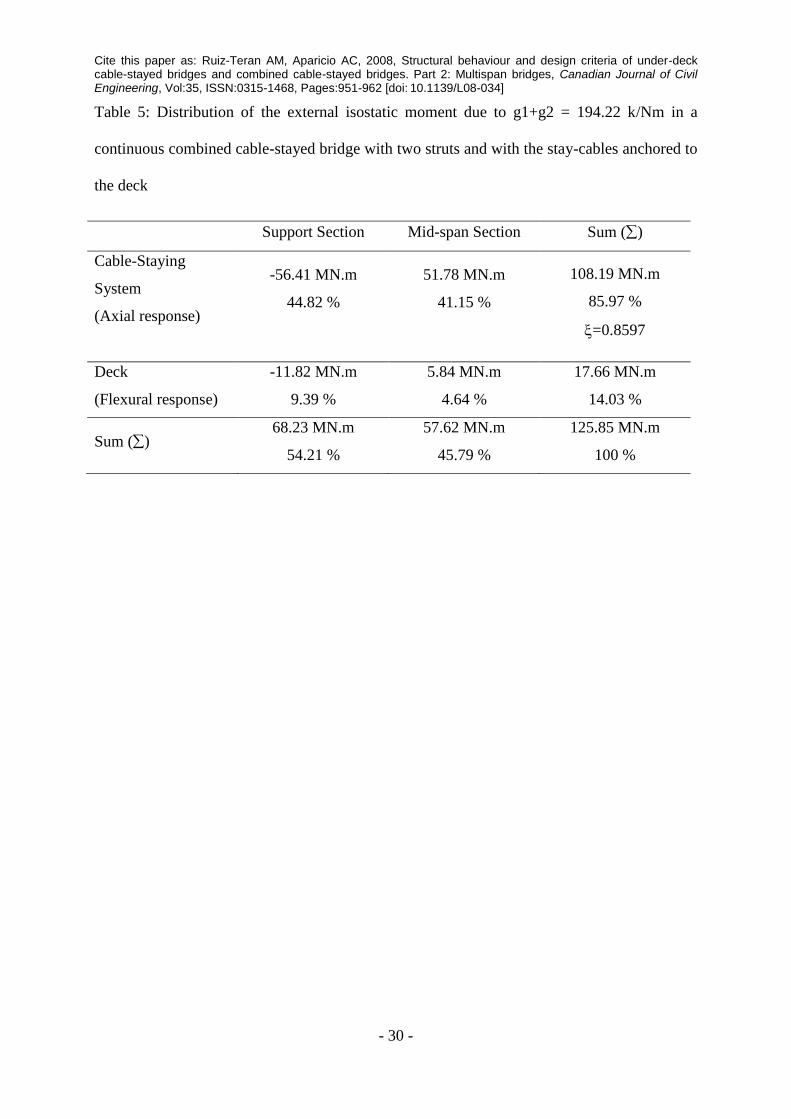
Comparing the preceding cases a) and b) in Table 4, it is shown that anchoring the stay-cables
to the deck in continuous bridges produce several advantages: (1) a greater span subdivision
in permanent state (1/5 against 1/3); (2) a higher efficiency of the cable-staying system (0.86

Cite this paper as: Ruiz-Teran AM, Aparicio AC, 2008, Structural behaviour and design criteria of under-deck cable-stayed bridges and combined cable-stayed bridges. Part 2: Multispan bridges, Canadian Journal of Civil Engineering, Vol:35, ISSN:0315-1468, Pages:951-962 [doi:
10.1139/L08-034]
- 13 -
against 0.78); (3) smaller hogging bending moments due to traffic live load; (4) a reduction in
the amount of internal prestressing by half; (5) a reduction in the total amount of active steel
by 25%; and (6) a lower concrete characteristic strength (35 against 55 MPa). The key point
that produces all these advantages is the increase in the response of the extradosed stay cables
when they are anchored to the deck. Comparing Tables 3 and 5, that justify the efficiencies in
cases a) and b) respectively, it is seen how the component provided by the extradosed stay
cables at the support section over piers is doubled, significantly increasing the efficiency of
the cable-staying system. Therefore, scheme b), using stay cables anchored to the deck, is
very appropriate from both structural and economical points of view. Comparing it with a
conventional bridge (without stay cables), the deck depth is reduced to 25%, the self-weight
and the concrete amount to 60%, and the total amount of active steel to 40%. In addition,
these reductions are achieved using conventional anchorages of external prestressing and
concrete with a conventional strength. The greatest drawback of this scheme is that all the
stay cables (intradosed and extradosed stay cables) must be anchored in the same section, this
constitutes an extra intricacy in both design and construction stages. In order to avoid this
disadvantage, case c) has been considered, using the same cross section for the deck (Figure
6). However, there is one limit state that is not satisfied, the vibration SLS, since the
maximum vertical accelerations in the deck rise beyond the limit following an increase of
over 40%. In order to satisfy this SLS, it is necessary to increase the depth of the deck, but
this leads to both reducing the efficiency of the cable-staying system and increasing the cost
in materials.
4. Comparative analysis of under-deck cable-staying systems and combined cable-
staying systems for multi-span continuous bridges
Under-deck cable-staying systems allow permanent load to be compensated by means of the
stay cable prestressing, giving rise to the span subdivision in permanent state. However, these

Cite this paper as: Ruiz-Teran AM, Aparicio AC, 2008, Structural behaviour and design criteria of under-deck cable-stayed bridges and combined cable-stayed bridges. Part 2: Multispan bridges, Canadian Journal of Civil Engineering, Vol:35, ISSN:0315-1468, Pages:951-962 [doi:
10.1139/L08-034]
- 14 -
cable-staying layouts are not efficient under traffic live load as long as their eccentricities are
suitable from an aesthetic point of view. The contribution of the cable-staying system to
resisting external hogging bending moments due to traffic live load at the critical support
section over piers is very small and, consequently, the bending ULS at these sections
determines the depth of the deck. In comparison with conventional bridges without stay
cables, the depth of the deck is reduced by half and the self-weight by 25%, but the total
amount of active steel is similar and a greater concrete characteristic strength is required. The
cost in materials of these schemes is very similar to that of conventional bridges and
additional structural elements (struts) must be employed.
On the other hand, combined cable-staying systems with the stay-cables anchored to the deck
allow the span subdivision in permanent state (even after accounting for time-dependent
effects) and have a high efficiency under traffic live load. The reduction in the self-weight of
the deck leads us to consider the possible increase of the span range of construction by means
of self-launching gantries. Furthermore, the reduction in the amounts of all the materials of
the deck leads us to think about these structural types as competitive schemes even from an
economical point of view. For instance, the cost of materials of the deck of a combined cable-
stayed bridge with 80-metre spans is similar to that of a conventional bridge (without stay
cables) with 40-metre spans. This statement is based on a simple economic analysis in which
the main deck components (such as concrete, formwork, internal prestressing, stay cables, and
passive reinforcement) have been assessed using the current prices in the Spanish market.
Additionally, in comparison with the conventional bridge, although the total construction
budget of the combined cable-stayed bridge would include some extra elements, such as
pylons and struts, many others would be removed, such as half of the piers and their
respective foundations. Therefore, this is a suitable scheme for viaducts crossing wide valleys
since, beside of being appropriate from various (structural, constructive, economical and
Cite this paper as: Ruiz-Teran AM, Aparicio AC, 2008, Structural behaviour and design criteria of under-deck cable-stayed bridges and combined cable-stayed bridges. Part 2: Multispan bridges, Canadian Journal of Civil Engineering, Vol:35, ISSN:0315-1468, Pages:951-962 [doi:
10.1139/L08-034]
- 15 -
architectural) points of view, it can be justified by taking into account considerations related
to landscape integration (the ‘barrier effect’ is reduced by eliminating half the piers).
5. Continuous combined cable-stayed bridges with two and three spans
The application of unconventional cable-staying systems to bridges with two and three spans
has also been studied. As for multi-span continuous bridges, in bridges with two or three
spans, under-deck cable-staying schemes are not efficient under traffic live load as long as
their eccentricities are appropriate from an aesthetic point of view. Therefore, two-span
bridges and three-span bridges with combined cable-staying systems were designed, using
similar amounts of materials to those used in multi-span continuous bridges.
6. Design criteria
The analysis of the results and conclusions of the parametric study that has been conducted
has allowed us propose the design guidelines set out below.
6.1. Morphology
1) Structural elements. Decks of under-deck cable-stayed bridges require struts and under-
deck stay cables. Decks of combined cable-stayed bridges require struts, combined stay
cables, pylons, and, in the particular case of the end spans, back stay cables and anchorage
counterweights.
2) Types of cable-staying systems. There are three possible layouts for multi-span bridges
with unconventional cable-staying systems: (1) continuous bridges with combined cable-
staying systems, (2) semi-continuous bridges with under-deck cable-staying systems, with
independent spans joined by means of continuity slabs to ensure road-users’ comfort, and (3)
continuous bridges with under-deck cable-staying systems. In the first two schemes the cable-
staying system is very efficient under traffic live load, making it possible to design very
Cite this paper as: Ruiz-Teran AM, Aparicio AC, 2008, Structural behaviour and design criteria of under-deck cable-stayed bridges and combined cable-stayed bridges. Part 2: Multispan bridges, Canadian Journal of Civil Engineering, Vol:35, ISSN:0315-1468, Pages:951-962 [doi:
10.1139/L08-034]
- 16 -
slender and economical structures. In the third scheme, the cable-staying system is very
inefficient under traffic live load —if the eccentricity of the cable-staying system is limited by
aesthetic considerations—, and even the span subdivision achieved after prestressing the stay
cables does not remain indefinitely due to time-dependent effects, making this scheme not
particularly attractive from structural and economical points of view. For the design of under-
deck cable-stayed bridges with independent spans, the design criteria for single-span bridges
with under-deck cable-staying systems will be applicable (Ruiz-Teran and Aparicio 2007c).
For the design of continuous bridges with unconventional cable-staying systems, the
following criteria set out below will be applicable.
3) Layout of cable-staying systems. In the case of multi-span continuous bridges with
combined cable-staying systems, the layouts must be designed in order to ensure the
efficiency of the cable-staying systems even if traffic live load acts on alternate spans. The
standard schemes for classic cable-stayed bridges with multiple spans, that control the
movement of the tower heads, are valid although two of them are the most appropriate: (1) the
use of towers with large flexural stiffness and (2) splitting of the pylon into two inclined legs
doubling the supports of the deck over the piers.
4) Connection of the stay cables to the deck. In combined cable-stayed bridges it is possible
to choose between two different connections at the section where the stay cables cross
through the deck: (1) stay cables anchored to the deck or (2) stay cables not connected to the
deck, but rather passing through guide pipes where they go through the deck cross-section.
When the stay cables are anchored to the deck, a greater span subdivision is achieved, along
with a larger efficiency of the cable-staying system and a reduction of the amount of materials
used for the deck. However, the need to anchor all the extradosed and intradosed stay cables
in the same section introduces an extra intricacy in both design and construction stages. In
continuous bridges with under-deck cable-staying systems, the stay cables will be self-

Cite this paper as: Ruiz-Teran AM, Aparicio AC, 2008, Structural behaviour and design criteria of under-deck cable-stayed bridges and combined cable-stayed bridges. Part 2: Multispan bridges, Canadian Journal of Civil Engineering, Vol:35, ISSN:0315-1468, Pages:951-962 [doi:
10.1139/L08-034]
- 17 -
anchored in the support sections of the deck over piers and abutments.
5) Span Subdivision. Location of the connection points of the cable-staying system to the
deck. Span subdivision is achieved thanks to the prestressing of the stay cables, compensating
100% of the permanent load (dead load and superimposed dead load). When the span is
subdivided, the bending of the deck in permanent state is reduced to the local bending
between the sections of the deck which are connected to the cable-staying system (the
sections where the deck lays over the struts and the sections where the stay cables are
anchored to the deck) and the supports sections of the deck over piers. These sections must be
uniformly distributed over the length of the deck.
6) Depth of the deck. In order to make the cable-staying system more efficient under live
load, the smallest depth that satisfies both the bending ULS and the vibration SLS will be
specified. For continuous bridges with 80-metre spans, the depth/span ratio can be equal to
1/100 if a combined cable-staying system is disposed and 1/50 in the case of an under-deck
cable-staying system.
7) Connection between the deck and the struts. The struts should be connected to the deck by
means of pins in order to avoid the introduction of concentrated bending moments into the
slender decks and struts as well as to strengthen the axial response. Diaphragms should be
employed in these sections. For stressing the intradosed stay cables, temporary props are used
to immobilise the struts during the stressing process.
8) Orientation of the struts. The struts are placed along the bisector of the angle formed by
the stay cables in order to ensure that the stress is constant all along the stay cable, allowing
the optimum design of the stay cables.
9) Eccentricity of the cable-staying systems. Eccentricities at mid-span sections and support
sections on the order of 1/10 of the span are appropriate for these types of structures.

Cite this paper as: Ruiz-Teran AM, Aparicio AC, 2008, Structural behaviour and design criteria of under-deck cable-stayed bridges and combined cable-stayed bridges. Part 2: Multispan bridges, Canadian Journal of Civil Engineering, Vol:35, ISSN:0315-1468, Pages:951-962 [doi:
10.1139/L08-034]
- 18 -
Although larger eccentricities increase structural efficiency, they are unsuitable from an
aesthetic point of view (Ruiz-Teran and Aparicio 2007b). The eccentricity used should be a
compromise between structural and aesthetic considerations.
10) Layout of the cable-staying systems. Once both the points where the deck lays over the
struts and the eccentricity of the cable-staying system at critical sections have been
established, the layout of the stay cables is determined by means of three conditions: (1)
eccentricity at the critical sections must be as established; (2) all the struts are placed along
the bisector of the angle formed by the stay cables; and (3) the vertical component of the
deviation forces introduced through the struts into the deck must be uniform, in order to
compensate the permanent load, which is also uniform.
11) Layout of the internal prestressing. The layout will be similar to that of a bridge with
supports at the points where the cable-staying system is connected to the deck (the sections
where the deck lays over the struts and the sections where stay cables are anchored to the
deck), in addition to the supports of the deck over piers.
12) Sections of the deck. Voided slabs are appropriate, since the efficiency of the cable-
staying system increases with the reduction of the radius of gyration of the deck (Ruiz-Teran
and Aparicio 2007b). The space between voids will be established by the placement of the
internal prestressing and by construction requirements, but not by the verification of the shear
ULS which will be amply satisfied.
6.2. Limit states that govern the dimensions of the different structural elements
1) Cross-section of the stay cables. The cross-section of the stay cables is determined by the
ULS of fatigue that is linked to the anchorage technology used: stay-cable anchorages
(max0.45fpu and max200 MPa) or conventional external-prestressing anchorages
(max0.65fpu and max80 MPa). This limit state requires a double verification: (1) the

Cite this paper as: Ruiz-Teran AM, Aparicio AC, 2008, Structural behaviour and design criteria of under-deck cable-stayed bridges and combined cable-stayed bridges. Part 2: Multispan bridges, Canadian Journal of Civil Engineering, Vol:35, ISSN:0315-1468, Pages:951-962 [doi:
10.1139/L08-034]
- 19 -
maximum stress must be less than max and (2) the variation in stress due to frequent live load
must be less than max. Stress changes due to rotation of the anchorages of the stay cables as
well as the wind effects should be considered if they are not negligible. If the cable-staying
systems have a high efficiency, as in the case of continuous combined cable-stayed bridges,
the critical verification is that associated with the variation in stress. If the cable-staying
systems have a low efficiency, as in the case of continuous with under-deck cable-stayed
bridges, the critical verification is that related to the maximum stress.
2) Depth of the deck. For medium spans (80 metres), the depth of the deck in continuous
combined cable-stayed bridges is governed by the vibration SLS, whereas in continuous
under-deck cable-stayed bridges it is governed by the bending ULS.
3) Characteristic strength of the concrete of the deck. It is advisable to use the minimum
strength that both ensures the verification of the stress limitation SLS and the durability of the
structure.
4) Amount of internal prestressing. In contrast with conventional bridges, the amount of
prestressing is conditioned by the controlled cracking SLS and even by the bending ULS.
Attempting to satisfy these limit states through the increase of the passive reinforcement
(using only the internal prestressing required to satisfy the decompression SLS) gives rise to
sections that are so highly reinforced that they are not very recommendable from both
construction and durability points of view.
5) Amount of internal reinforcement. Because of the large reduction of the flexural response
of the deck and in order to avoid a brittle failure, it is necessary to verify the bending ULS
taking into consideration the hogging and sagging cracking bending moments if they are
larger than the design bending moments.
7. Conclusions

Cite this paper as: Ruiz-Teran AM, Aparicio AC, 2008, Structural behaviour and design criteria of under-deck cable-stayed bridges and combined cable-stayed bridges. Part 2: Multispan bridges, Canadian Journal of Civil Engineering, Vol:35, ISSN:0315-1468, Pages:951-962 [doi:
10.1139/L08-034]
- 20 -
A complete and systematic parametric study of multi-span continuous bridges with two
innovative structural types (under-deck cable-stayed bridges and combined cable-stayed
bridges) has been undertaken. Their structural response has been analysed and a set of design
criteria has been established (Section 6). Although many of the conclusions are of a generic
nature, the study focuses on road bridges with medium spans (80 m) and prestressed concrete
decks. In view of the structural behaviour, Conclusions must be split in three different
sections:
7.1. Multi-span continuous bridges with under-deck cable-staying systems
1) For this type of bridge, the axial response is not clearly enhanced, since cable-staying
systems without eccentricities at the support sections are not appropriate for continuous
bridges. The span subdivision attained after stressing the stay cables is partially lost due
to time-dependent effects. In addition, the efficiencies of these cable-staying systems
under traffic live load are very low as long as the eccentricities of the stay cables are
admissible from an aesthetical point of view.
2) The depth of the deck can be smaller than that in conventional schemes without stay
cables, but savings are not significant due to the type of materials required (concrete with
a higher characteristic strength, and external prestressing anchorages with higher fatigue
strength).
3) Consequently, the use of under-deck cable-staying systems for continuous bridges is not
justified from both structural and economical points of view.
7.2. Semi-continuous decks with under-deck cable-staying systems
1) Under-deck cable-staying systems applied to multi-span bridges have high efficiencies
only if semi-continuous schemes with independent spans are designed. Design criteria for
single-span bridges (Ruiz-Teran and Aparicio 2007c) are applicable to these bridges and

Cite this paper as: Ruiz-Teran AM, Aparicio AC, 2008, Structural behaviour and design criteria of under-deck cable-stayed bridges and combined cable-stayed bridges. Part 2: Multispan bridges, Canadian Journal of Civil Engineering, Vol:35, ISSN:0315-1468, Pages:951-962 [doi:
10.1139/L08-034]
- 21 -
road users’ comfort is ensured by means of flexible continuity slabs between adjacent
decks.
2) In comparison with conventional schemes without stay cables, a 30% reduction in the
amount of the materials used in the decks is achieved.
3) These types of bridges can be justified from structural, economical and aesthetical points
of view.
7.3. Multi-span continuous bridges with combined cable-staying systems
1) In permanent state, the span subdivision is achieved through the prestressing of the stay
cables (compensating 100% of dead load and superimposed dead load), the placement of
intermediate struts and the possible anchorage of the stay cables to the deck. The axial
response (tension of the stay cables and compression of the deck, the struts and the
pylons) is enhanced whereas the flexural response is reduced to the local bending of the
deck between the support sections, over the struts and the piers, as well as the possible
anchorage sections of stay cables to the deck. The span subdivision is not affected by
time-dependent effects, since the stress losses in the stay cables are very small (2%).
2) Under the traffic live load, the axial response is also enhanced in relation to the flexural
response. The larger total eccentricity (the sum of the eccentricities at the support and
mid-span sections) of these combined cable-staying systems provides a higher efficiency
(80%) that can even be increased further by anchoring the stay cables to the deck (90%).
This high efficiency leads to the ULS of fatigue being the critical limit state for
determining the cross-sectional area of the stay cables.
3) The strengthening of the axial response makes it possible to design extremely slender
bridges that make an efficient structural use of the materials disposed. Combine cable-
staying systems applied to multi-span continuous bridges with spans of medium length

Cite this paper as: Ruiz-Teran AM, Aparicio AC, 2008, Structural behaviour and design criteria of under-deck cable-stayed bridges and combined cable-stayed bridges. Part 2: Multispan bridges, Canadian Journal of Civil Engineering, Vol:35, ISSN:0315-1468, Pages:951-962 [doi:
10.1139/L08-034]
- 22 -
(80 m) allow the design of much smaller deck depths (1/100 of the span). In comparison
with conventional continuous schemes without stay cables, the deck depth is reduced to
25%, the amount of concrete to 60%, and the total amount of active steel (internal
prestressing and stays cable) to 40%. These reductions are attained using conventional
concrete (35 MPa) and conventional anchorages for external prestressing
4) The substantial reduction in the depth of the deck also involves a significant increase in
the vertical accelerations associated with the dynamic response of the structure to traffic
live load. In bridges with spans of medium length, the depth of the deck may be governed
by the vibration SLS.
5) These are innovative schemes that can extend the applicable range of conventional
construction methods, such as the construction of viaducts by means of both self-
launching gantries and longitudinal precast elements.
6) These schemes can be expected to be very competitive and even more economical than
conventional schemes due to the substantial reduction in both the amounts of materials
used for the decks and the design actions over other structural elements (such as
bearings, abutments, piers and foundations).
7) These schemes can be very suitable for wide valleys. The ‘barrier effect’ of the piers can
be reduced, enhancing the landscape integration, without an increase in cost.
8) The fact that the stay cables are partially located above the deck, framing and bounding
the space of passage over the structure, can mean an extra value, from an aesthetic point
of view. This effect is achieved with smaller towers than that in cable-stayed bridges,
again contributing to the landscape integration.
9) Provide the presence of sufficient vertical clearance, these original and innovative
schemes (as far as the authors’ knowledge, no one has yet built any continuous road
Cite this paper as: Ruiz-Teran AM, Aparicio AC, 2008, Structural behaviour and design criteria of under-deck cable-stayed bridges and combined cable-stayed bridges. Part 2: Multispan bridges, Canadian Journal of Civil Engineering, Vol:35, ISSN:0315-1468, Pages:951-962 [doi:
10.1139/L08-034]
- 23 -
bridges of this type) are the most suitable and competitive schemes for bridges with
multiple spans of medium length, due to their structural efficiency, enhanced
construction methods, both economical and aesthetical considerations, as well as
landscape integration possibilities.

Cite this paper as: Ruiz-Teran AM, Aparicio AC, 2008, Structural behaviour and design criteria of under-deck cable-stayed bridges and combined cable-stayed bridges. Part 2: Multispan bridges, Canadian Journal of Civil Engineering, Vol:35, ISSN:0315-1468, Pages:951-962 [doi:
10.1139/L08-034]
- 24 -
References
BS 5400-2 1978. Steel, concrete and composite bridges. Part 2. Specification for loads.
Cusens, A.R., and Pama, R.P. 1975. Bridge deck analysis. John Wiley and Sons, London.
EHE 1999. Structural Concrete Code. Ministerio de Fomento, Spain (In Spanish)
Eurocode 2-1-1 2004. Design of Concrete Structures. Part 1-1. EN 1992-1-1.
Eurocode 2-2 2001. Eurocode 2. Design of concrete structures. Part 2. Concrete bridges. EN
1992-2
Gimsing, N.J. 1997. Cable supported bridges. Concept and design. Wiley.
Fomento 1999. Guideline for the development of load tests in road bridges. Ministerio de
Fomento, Spain. (In Spanish)
Holgate, A. 1997. The art of structural engineering. The work of Jörg Schlaich and his team.
Edition Alex Menges, Stuttgart.
IAP 1998. Actions Code for road bridges design. Ministerio de Fomento, Spain. (In Spanish)
Manterola, J., and Rodado, J. 2000. Continuous Cable Stayed Bridges. Hormigón y Acero,
217: 3-35 (In English and Spanish).
Ruiz-Teran A.M. 2005. Unconventional cable-stayed bridges. Structural behaviour and design
criteria. Doctoral Thesis. Supervised by A.C. Aparicio. University of Cantabria, Spain (in
Spanish).
Ruiz-Teran, A.M., and Aparicio, A.C. 2007a. Two new types of bridges: under-deck cable-
stayed bridges and combined cable-stayed bridges. The state of the art. Canadian Journal of
Civil Engineering, 34(8): 1003-1015
Ruiz-Teran, A.M., and Aparicio, A.C. 2007b. Parameters governing the response of under-

Cite this paper as: Ruiz-Teran AM, Aparicio AC, 2008, Structural behaviour and design criteria of under-deck cable-stayed bridges and combined cable-stayed bridges. Part 2: Multispan bridges, Canadian Journal of Civil Engineering, Vol:35, ISSN:0315-1468, Pages:951-962 [doi:
10.1139/L08-034]
- 25 -
deck cable-stayed bridges. Canadian Journal of Civil Engineering, 34(8):1016-1024
Ruiz-Teran, A.M., and Aparicio, A.C. 2007c. Structural behaviour and design criteria of
under-deck cable-stayed bridges and combined cable-stayed bridges. Single span bridges.
Canadian Journal of Civil Engineering (accepted for publication)
Walter, R. 1999. Cable Stayed Bridges. Thomas Telford.

Cite this paper as: Ruiz-Teran AM, Aparicio AC, 2008, Structural behaviour and design criteria of under-deck cable-stayed bridges and combined cable-stayed bridges. Part 2: Multispan bridges, Canadian Journal of Civil Engineering, Vol:35, ISSN:0315-1468, Pages:951-962 [doi:
10.1139/L08-034]
- 26 -
Table 1: Distribution of the external isostatic moment due to g1+g2 = 234.95 kN/m in a
continuous under-deck cable-stayed bridge with 2 struts
Support Section Mid-span Section Sum ()
Cable-Staying
System
(Axial response)
0 MN.m
0 %
51.80 MN.m
27.56 %
51.80 MN.m
27.56 %
=0.2756
Deck
(Flexural response)
-90.77 MN.m
48.29 %
45.39 MN.m
24.15 %
136.16 MN.m
72.44 %
Sum () -90.77 MN.m
48.29 %
97.19 MN.m
51.71 %
187.96 MN.m
100 %

Cite this paper as: Ruiz-Teran AM, Aparicio AC, 2008, Structural behaviour and design criteria of under-deck cable-stayed bridges and combined cable-stayed bridges. Part 2: Multispan bridges, Canadian Journal of Civil Engineering, Vol:35, ISSN:0315-1468, Pages:951-962 [doi:
10.1139/L08-034]
- 27 -
Table 2: Comparison of Under-Deck Cable-Stayed Bridges
Continuous schemes
at the support section over piers
Discontinuous
scheme
Without
stay cables 1 strut 2 struts 2 struts
Depth / Span 1/25 1/50 1/50 1/80
Section type box girder box girder box girder voided slab
Self-weight (kN/m) 259 192 192 188
Total amount of
active steel a
0.68 0.70 0.63 0.48
Amount of internal
prestressing in the
decka
0.68 0.49 0.42 0.20
Stay cable amount a 0 0.21 0.21 0.28
fck (MPa) 35 50 40 40
Bending moments in permanent state
Without time-dependent effects
Maximum (MN.m) 80.57 15.66 6.97 10.99
Minimum (MN.m) -161.15 -31.32 -13.93 -16.45
With time-dependent effects
Maximum (MN.m) 80.57 15.69 13.36 13.50
Minimum (MN.m) -161.15 -40.12 -26.71 -11.99
Bending moments due to traffic live
load
Maximum (MN.m) 44.55 20.70 22.49 16.61
Minimum (MN.m) -46.07 -32.73 -27.65 -8.66
Efficiency of the cable-staying system ()
0.25 0.28 0.89
Acceleration due to heavy vehicles (m/s2)
0.03 0.07 0.06 0.41
a Amounts of active steel given in kg/m
2 / span (m)

Cite this paper as: Ruiz-Teran AM, Aparicio AC, 2008, Structural behaviour and design criteria of under-deck cable-stayed bridges and combined cable-stayed bridges. Part 2: Multispan bridges, Canadian Journal of Civil Engineering, Vol:35, ISSN:0315-1468, Pages:951-962 [doi:
10.1139/L08-034]
- 28 -
Table 3: Distribution of external isostatic moment due to g1+g2 = 194.22 kN/m in a
continuous combined cable-stayed bridge with 2 struts
Support Section Mid-span Section Sum ()
Cable-Staying
System
(Axial response)
-36.21 MN.m
28.77 %
61.92 MN.m
49.20 %
98.13 MN.m
77.97 %
=0.7797
Deck
(Flexural response)
-17.63 MN.m
14.01 %
10.09 MN.m
8.02 %
27.72 MN.m
22.03 %
Sum () -53.84 MN.m
42.78 %
72.01 MN.m
57.22 %
125.85 MN.m
100 %

Cite this paper as: Ruiz-Teran AM, Aparicio AC, 2008, Structural behaviour and design criteria of under-deck cable-stayed bridges and combined cable-stayed bridges. Part 2: Multispan bridges, Canadian Journal of Civil Engineering, Vol:35, ISSN:0315-1468, Pages:951-962 [doi:
10.1139/L08-034]
- 29 -
Table 4: Comparison of under-over-deck cable-stayed bridges
Under-deck
cable-stayed
bridge
Combined cable-stayed bridges
Stay cables
without deck
connection
(inside guide
pipes)
(case a)
Stay-cables
anchored at the
same section
(case b)
Stay-cables
anchored at
different sections
(case c)
Depth / Span 1/50 1/103 1/103 1/103
Number of strands
(extradosed stay cables) 122 186 140
Number of strands
(intradosed stay cables) 191 122 110 137
Total amount of active-
steela
0.63 0.36 0.27 0.31
Amount of internal
prestressing in the decka
0.42 0.22 0.11 0.12
Amount of stay cablesa 0.21 0.14 0.16 0.19
fck (MPa) 40 55 35 35
Bending moments in permanent state
Maximum (MN.m) 13.36 5.32 3.14 3.22
Minimum (MN.m) -26.71 -9.66 -4.55 -4.54
Bending moments due to traffic live load
Maximum (MN.m) 22.49 8.94 7.23 8.47
Minimum (MN.m) -27.65 -12.58 -6.33 -5.86
Efficiency of the cable-staying system ()
0.28 0.78 0.86 0.85
Acceleration due to heavy vehicles (m/s2)
0.06 0.52 0.46 0.65
Maximum allowed acceleration (m/s2)
0.45 0.52 0.54 0.49
a Amounts of active steel given in kg/m
2 / span(m)
Cite this paper as: Ruiz-Teran AM, Aparicio AC, 2008, Structural behaviour and design criteria of under-deck cable-stayed bridges and combined cable-stayed bridges. Part 2: Multispan bridges, Canadian Journal of Civil Engineering, Vol:35, ISSN:0315-1468, Pages:951-962 [doi:
10.1139/L08-034]
- 30 -
Table 5: Distribution of the external isostatic moment due to g1+g2 = 194.22 k/Nm in a
continuous combined cable-stayed bridge with two struts and with the stay-cables anchored to
the deck
Support Section Mid-span Section Sum ()
Cable-Staying
System
(Axial response)
-56.41 MN.m
44.82 %
51.78 MN.m
41.15 %
108.19 MN.m
85.97 %
=0.8597
Deck
(Flexural response)
-11.82 MN.m
9.39 %
5.84 MN.m
4.64 %
17.66 MN.m
14.03 %
Sum () 68.23 MN.m
54.21 %
57.62 MN.m
45.79 %
125.85 MN.m
100 %

Cite this paper as: Ruiz-Teran AM, Aparicio AC, 2008, Structural behaviour and design criteria of under-deck cable-stayed bridges and combined cable-stayed bridges. Part 2: Multispan bridges, Canadian Journal of Civil Engineering, Vol:35, ISSN:0315-1468, Pages:951-962 [doi:
10.1139/L08-034]
- 31 -
Figure captions
Figure 1: Osormort Viaduct, Spain (courtesy of Javier Manterola, Carlos Fernandez Casado
S.L.).
Figure 2: Continuous under-deck cable-stayed bridge: a) elevation, b) scheme and c) cross-
section.

Cite this paper as: Ruiz-Teran AM, Aparicio AC, 2008, Structural behaviour and design criteria of under-deck cable-stayed bridges and combined cable-stayed bridges. Part 2: Multispan bridges, Canadian Journal of Civil Engineering, Vol:35, ISSN:0315-1468, Pages:951-962 [doi:
10.1139/L08-034]
- 32 -
Figure 3: Bending moment diagrams in permanent state: a) due to g1 (dead load) + g2
(superimposed dead load) + prestressing of the stay cables; b) due to g1 + g2 + prestressing of
the stay cables + shrinkage + creep + relaxation (internal prestressing).
Figure 4: Bending moment envelopes due to traffic live load: a) q=52.8 kN/m (4 kN/m2); b)
Q=600kN (MQ TOTAL= 2MQ GRAPH).

Cite this paper as: Ruiz-Teran AM, Aparicio AC, 2008, Structural behaviour and design criteria of under-deck cable-stayed bridges and combined cable-stayed bridges. Part 2: Multispan bridges, Canadian Journal of Civil Engineering, Vol:35, ISSN:0315-1468, Pages:951-962 [doi:
10.1139/L08-034]
- 33 -
Figure 5: Elevation and schemes of combined cable-stayed bridges: a) with stay-cables
passing through the deck (not connected to the deck); b) with stay cables anchored to the
deck; c) with stay cables anchored to the deck in different sections.

Cite this paper as: Ruiz-Teran AM, Aparicio AC, 2008, Structural behaviour and design criteria of under-deck cable-stayed bridges and combined cable-stayed bridges. Part 2: Multispan bridges, Canadian Journal of Civil Engineering, Vol:35, ISSN:0315-1468, Pages:951-962 [doi:
10.1139/L08-034]
- 34 -
Figure 6: Combined cable-stayed bridges. Cross-sections: a) calculation cross-section and b)
real cross section and c) section showing the connection with a strut
Figure 7: Bending moment diagrams in permanent state: a) due to g1 (dead load) + g2
(superimposed dead load) + prestressing of the stay cables; b) due to g1 + g2 + prestressing of
the stay cables + shrinkage + creep + relaxation (internal prestressing).
Figure 8: Bending moment envelopes due to traffic live load: a) q=52.8 kN/m (4 kN/m2); b)
Q=600kN (MQ TOTAL= 2MQ GRAPH).
![Fast Multilevel Algorithms for Compressive Principal Component …spiral.imperial.ac.uk/bitstream/10044/1/66138/6/ML_RPCA... · 2019. 6. 28. · such as image denoising [6], background](https://img.pdfslide.us/doc/110x75/602a7b4e4bf9cc6c380d790a/fast-multilevel-algorithms-for-compressive-principal-component-2019-6-28-such.jpg)