Embed Size (px)
Citation preview
1 INTRODUCTION After more than four decades of research, interest in Fiber Reinforced Concrete (FRC) is continuously growing in many application fields. FRC is already widely used in structures where fiber reinforcement is inessential for integrity and safety, such as in slabs on grade or in first phase linings.
For structural purposes, steel fibers are becom-ing widely utilized since they enhance concrete toughness under tensile loading. This makes the ma-terial able to sustain tensile stresses after cracking and so allows stress redistribution.
Among the structural applications of steel fiber reinforced concrete (SFRC), there is a growing in-terest in precast tunnel segments to be used with the Tunnel Boring Machines, TBM (de Waal, 1999, Blom, 2002). These segments are generally made of ordinary reinforced concrete; however, the addition of fibers is gaining considerable attention among de-signers and producers due to the enhanced toughness that allows a partial or even total substitution of the conventional reinforcement.
In fact, the internal forces in a shield lining, in the final state, are usually a combination of a bend-ing moment and a hoop force, which could make possible to replace the traditional reinforcement mesh by steel fibers. Since fiber reinforcement is present in the cover zone also, tunnel segments have a better resistance against impact loads during instal-lation.
In the present paper, structural behavior of the segments for the Line T02 of Saronno-Malpensa
railway (Italy) are numerically simulated with nonlinear analyses.
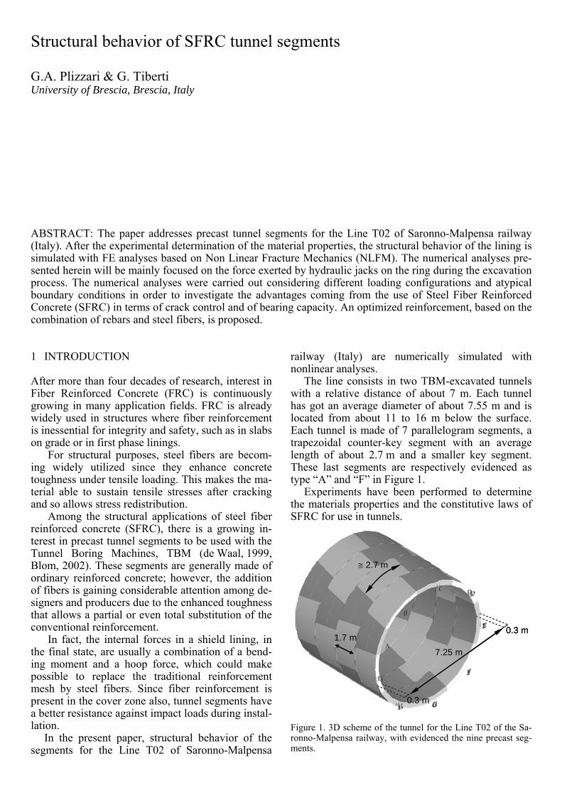
The line consists in two TBM-excavated tunnels with a relative distance of about 7 m. Each tunnel has got an average diameter of about 7.55 m and is located from about 11 to 16 m below the surface. Each tunnel is made of 7 parallelogram segments, a trapezoidal counter-key segment with an average length of about 2.7 m and a smaller key segment. These last segments are respectively evidenced as type “A” and “F” in Figure 1.
Experiments have been performed to determine the materials properties and the constitutive laws of SFRC for use in tunnels.
≅ 2.7 m
1.7 m0.3 m
7.25 m
0.3 m
≅ 2.7 m
1.7 m0.3 m
7.25 m
0.3 m
Figure 1. 3D scheme of the tunnel for the Line T02 of the Sa-ronno-Malpensa railway, with evidenced the nine precast seg-ments.
Structural behavior of SFRC tunnel segments
G.A. Plizzari & G. Tiberti University of Brescia, Brescia, Italy
ABSTRACT: The paper addresses precast tunnel segments for the Line T02 of Saronno-Malpensa railway (Italy). After the experimental determination of the material properties, the structural behavior of the lining is simulated with FE analyses based on Non Linear Fracture Mechanics (NLFM). The numerical analyses pre-sented herein will be mainly focused on the force exerted by hydraulic jacks on the ring during the excavation process. The numerical analyses were carried out considering different loading configurations and atypical boundary conditions in order to investigate the advantages coming from the use of Steel Fiber Reinforced Concrete (SFRC) in terms of crack control and of bearing capacity. An optimized reinforcement, based on the combination of rebars and steel fibers, is proposed.
Numerical analyses were performed by using a finite element model based on Non Linear Fracture Mechanics (NLFM; Hillerborg et al., 1976) with a smeared crack approach. These analyses allowed to study the structural behavior of the segments with several combinations of reinforcement under differ-ent loading conditions.
The numerical model was validated by using the experimental results of full-scale tests performed on SFRC precast tunnel segments without curvature (Hemmy, 2001). During the validation, different concrete crack models have been tested and com-pared.
An optimized reinforcement, based on a combina-tion of rebars and steel fibers, is proposed.
2 MATERIALS The experimental characterization of the material properties of SFRC was performed on a concrete matrix having the same strength of the one used for the railway Line T02 between Saronno and Mal-pensa.
Segments were reinforced with steel fibers 50/0.75, having a length Lf of 50 mm, a diameter φf of 0.75 mm and an aspect ratio Lf/φf equal to 67. These fibers are cold drawn, have a hooked shape, a rounded shaft and a tensile strength higher than 1100 MPa. Fibers were used with the volume frac-tions (Vf) equal to 0.38% (30 kg/m3).
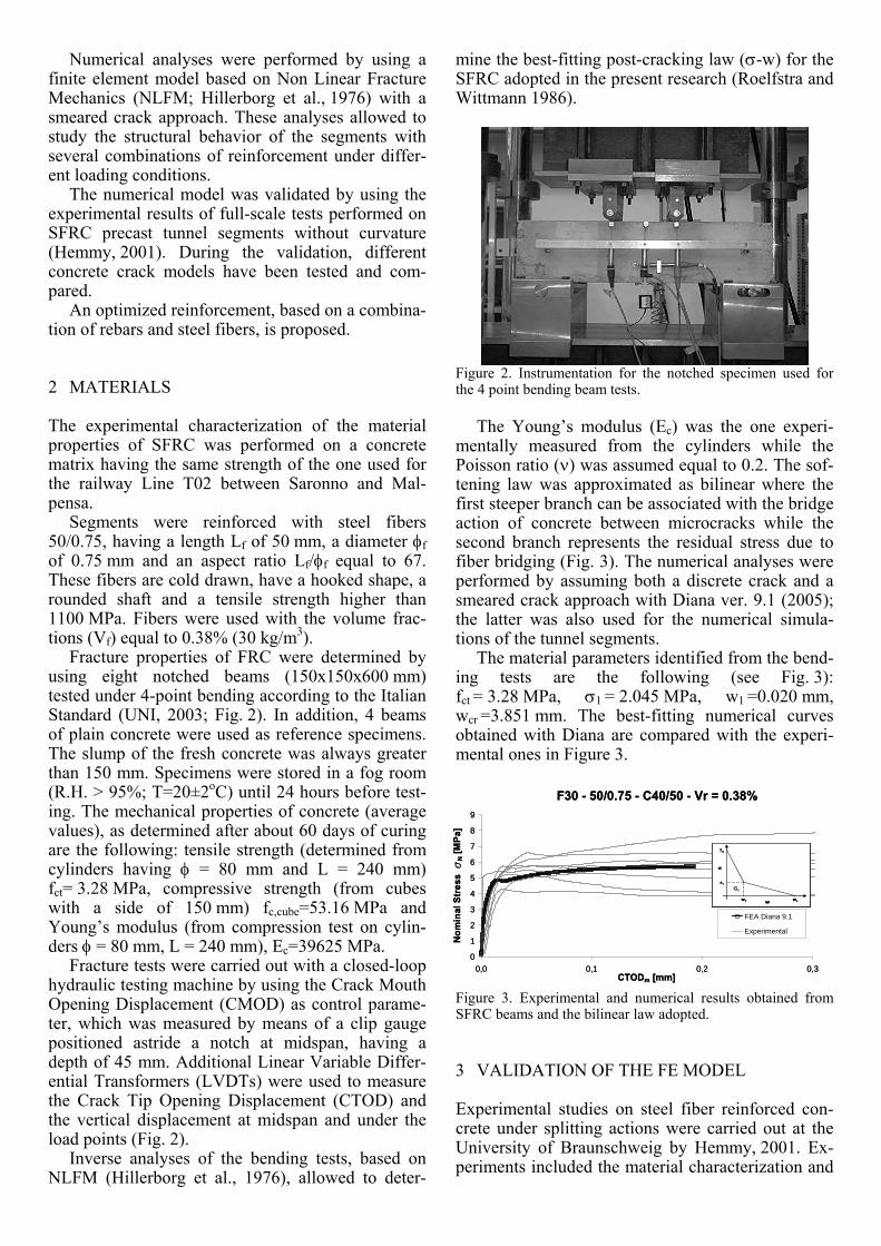
Fracture properties of FRC were determined by using eight notched beams (150x150x600 mm) tested under 4-point bending according to the Italian Standard (UNI, 2003; Fig. 2). In addition, 4 beams of plain concrete were used as reference specimens. The slump of the fresh concrete was always greater than 150 mm. Specimens were stored in a fog room (R.H. > 95%; T=20±2oC) until 24 hours before test-ing. The mechanical properties of concrete (average values), as determined after about 60 days of curing are the following: tensile strength (determined from cylinders having φ = 80 mm and L = 240 mm) fct= 3.28 MPa, compressive strength (from cubes with a side of 150 mm) fc,cube=53.16 MPa and Young’s modulus (from compression test on cylin-ders φ = 80 mm, L = 240 mm), Ec=39625 MPa.
Fracture tests were carried out with a closed-loop hydraulic testing machine by using the Crack Mouth Opening Displacement (CMOD) as control parame-ter, which was measured by means of a clip gauge positioned astride a notch at midspan, having a depth of 45 mm. Additional Linear Variable Differ-ential Transformers (LVDTs) were used to measure the Crack Tip Opening Displacement (CTOD) and the vertical displacement at midspan and under the load points (Fig. 2).
Inverse analyses of the bending tests, based on NLFM (Hillerborg et al., 1976), allowed to deter-
mine the best-fitting post-cracking law (σ-w) for the SFRC adopted in the present research (Roelfstra and Wittmann 1986).
Figure 2. Instrumentation for the notched specimen used for the 4 point bending beam tests.
The Young’s modulus (Ec) was the one experi-
mentally measured from the cylinders while the Poisson ratio (ν) was assumed equal to 0.2. The sof-tening law was approximated as bilinear where the first steeper branch can be associated with the bridge action of concrete between microcracks while the second branch represents the residual stress due to fiber bridging (Fig. 3). The numerical analyses were performed by assuming both a discrete crack and a smeared crack approach with Diana ver. 9.1 (2005); the latter was also used for the numerical simula-tions of the tunnel segments.
The material parameters identified from the bend-ing tests are the following (see Fig. 3): fct = 3.28 MPa, σ1 = 2.045 MPa, w1 =0.020 mm, wcr =3.851 mm. The best-fitting numerical curves obtained with Diana are compared with the experi-mental ones in Figure 3.
F30 - 50/0.75 - C40/50 - Vr = 0.38%
0
1
2
3
4
5
6
7
8
9
0,0 0,1 0,2 0,3CTODm [mm]
Nom
inal
Str
ess
sN [M
Pa]
FEA Diana 9.1
Experimental
σ
w1 wcw
fct
s1
Gf
σ
w1 wcw1 wcw
fct
s1
Gf
F30 - 50/0.75 - C40/50 - Vr = 0.38%
0
1
2
3
4
5
6
7
8
9
0,0 0,1 0,2 0,3CTODm [mm]
Nom
inal
Str
ess
sN [M
Pa]
FEA Diana 9.1
Experimental
σ
w1 wcw
fct
s1
Gf
σ
w1 wcw1 wcw
fct
s1
Gf
σ
w1 wcw
fct
s1
Gf
σ
w1 wcw1 wcw
fct
s1
Gf
Figure 3. Experimental and numerical results obtained from SFRC beams and the bilinear law adopted.
3 VALIDATION OF THE FE MODEL Experimental studies on steel fiber reinforced con-crete under splitting actions were carried out at the University of Braunschweig by Hemmy, 2001. Ex-periments included the material characterization and

the structural tests under point or line loads to assess the performance of SFRC under bi-axial and tri-axial stress concentrations.
The experimental results were used to validate the FE model used in the present research work. In particular, the simulation of the splitting test on a full-scale SFRC segment without curvature is pre-sented herein.
Figure 4 shows the experimental set-up that con-sists of a segment on two supports subjected to two concentrated loads. This test aimed to simulate typi-cal actions for precast tunnel segments, represented by the high concentrated forces of the TBM hydrau-lic jacks.
Figure 4. Configuration of the splitting test on full-scale seg-ments without curvature (Hemmy, 2001).
The concrete used in the test has a strength class
C40/50. The specimen has been reinforced with 35 kg/m3 of steel fibers having an aspect ratio of 65. Material properties of concrete with 40 kg/m3 of fi-bers 50/0.75 were used for the numerical simulation, since they were determined from previous tests. As the materials are not exactly the same, the main aim of this comparison was to capture the general trend of the experimental results.
Figure 4 shows the test configuration with the LVDTs (Linear Variable Differential Transformers) used to measure the crack openings under loading areas. A comparison between the experimental and the numerical load-displacement curve is shown in Figure 5. One should notice the good agreement be-tween the two curves; also the numerical crack pat-terns are similar to the experimental ones (Fig. 6).
0
1
2
3
4
5
6
7
8
9
10
0 0,2 0,4 0,6 0,8 1 1,2
ε, LVDT [‰]
Load
[MN
]
FEA DIANA 9.1
Experimental
LVDT LVDT
0
1
2
3
4
5
6
7
8
9
10
0 0,2 0,4 0,6 0,8 1 1,2
ε, LVDT [‰]
Load
[MN
]
FEA DIANA 9.1
Experimental
LVDT LVDTLVDT LVDT
Figure 5. Comparison between numerical and experimental load-LVDTS curves: splitting test in a SFRC segment without curvature.
Numerical Crack Patterns
Experimental Crack Patterns
Numerical Crack Patterns
Experimental Crack Patterns
Figure 6. Comparison between numerical and experimental crack patterns from splitting test in a SFRC segment (Hemmy, 2001).
4 DESIGN ASPECTS An open question for the construction companies and the designers concerns the reinforcement for these precast elements. In fact, an heavy conven-tional reinforcement is quite complex and labor-intensive to construct; it also needs a relatively large storage area before placing it in the segment. Fig-ure 7 shows the conventional reinforcement adopted for the segments of the Saronno-Malpensa railway; it corresponds to an equivalent weight of 82 kg/m3.
Figure 7. Scheme of conventional reinforcement (rebars) used in precast tunnel segments of the Saronno-Malpensa railway.
Generally, reinforcement is designed according to
the design actions on the tunnel segments, resulting from segment transportation, placing process and soil pressure in the final state.
In particular, during construction, the thrust forces and the grout pressure are the most critical factors. Cracks often appears in the tunnel lining in the phase in which these forces occur. Some exam-ples of cracks that typically appear in segmental tun-nel linings are shown in Figure 8. Possible causes of these cracks could be eccentricity or inclination of the thrust jacks. Also, a number of phenomena due to the trumpet shape as the torsional deformation or a non-smooth support of the ring joint, may cause these cracks.
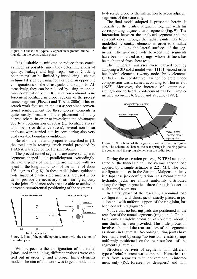
Figure 8. Cracks that typically appear in segmental tunnel lin-ings during the construction phase.
It is desirable to mitigate or reduce these cracks
as much as possible since they determine a loss of quality, leakage and high repair costs. Cracking phenomena can be limited by introducing a change in tunnel design by using, for example, an opportune configurations of the thrust jacks and supports. Al-ternatively, they can be reduced by using an oppor-tune combination of SFRC and conventional rein-forcement localized in proper regions of the precast tunnel segment (Plizzari and Tiberti, 2006). This re-search work focuses on the last aspect since conven-tional reinforcement for these precast elements is quite costly because of the placement of many curved rebars. In order to investigate the advantages due to a combination of rebar (for localized stress) and fibers (for diffusive stress), several non-linear analyses were carried out, by considering also very un-favorable boundary conditions.
Based on the material properties described in § 2, the total strain rotating crack model provided by DIANA was adopted for FE simulations.
The precast tunnel segments are universal tapered segments shaped like a parallelogram. Accordingly, the radial joints of the lining are inclined with re-spect to the longitudinal axis of the tunnel of about 10° degrees (Fig. 8). In these radial joints, guidance rods, made of plastic rigid materials, are used in or-der to provide the necessary shear bearing capacity to the joint. Guidance rods are also able to achieve a correct circumferential positioning of the segments.
Direction of excavation
Parallelogram segment Section of the radial joint
≅ 10°
SEGMENT SEGMENT
GASKET
GUIDANCE ROD
Direction of excavation
Parallelogram segment Section of the radial joint
≅ 10°≅ 10°
SEGMENT SEGMENT
GASKET
GUIDANCE ROD
Figure 8. Plan of the parallelogram segment with the section of the radial joint.
With respect to the configuration of the radial
joints used in the lining, different analyses were car-ried out in order to find a proper finite elements model. The aim of this work was to get a model able
to describe properly the interaction between adjacent segments of the same ring.
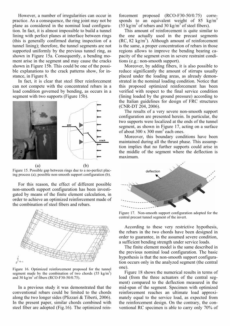
The final model adopted is presented herein. It consists of the central segment, together with his corresponding adjacent two segments (Fig. 9). The interaction between the analysed segment and the adjacent ones, through the radial joints, has been modelled by contact elements in order to simulate the friction along the lateral surfaces of the seg-ments. The guidance rods between the segments have been simulated as springs, whose stiffness has been obtained from shear tests.
The numerical analyses were carried out by adopting a 3D solid model with 11151 second order hexahedral elements (twenty nodes brick elements CHX60). The constitutive law for concrete under compression was assumed according to Thorenfeldt (1987). Moreover, the increase of compressive strength due to lateral confinement has been imple-mented according to Selby and Vecchio (1993).
analysed segment
radial joints:-contact elem.;-spring elem.
ring joints:spring elem.
analysed segmentanalysed segment
radial joints:-contact elem.;-spring elem.
ring joints:spring elem.ring joints:spring elem.
Figure 9. 3D scheme of the segment: nominal load configura-tion. The scheme evidenced the rear springs in the ring joints, the contact and the spring elements in the radial joints
During the excavation process, 29 TBM actuators
acted on the tunnel lining. The average service load applied by a single actuator is 2.21 MN. The load configuration used in the Saronno-Malpensa railway is a Japanese jack configuration. This means that the hydraulic jacks are almost uniformly distributed along the ring; in practice, three thrust jacks act on each tunnel segments.
In a first phase of the research, a nominal load configuration with thrust jacks exactly placed in po-sition and with uniform support of the ring joint, has been considered (Figure 9).
Notice that no bearing pads are positioned in the rear face of the tunnel segments (ring joints). On that face, only a slightly protusion of concrete, about 3 mm thick, has been provided. This little protusion involves about all the rear surfaces of the segments, as shown in Figure 10. Accordingly, ring joints have been simulated by using “no-tension” elastic springs uniformly positioned on the rear surfaces of the segments (Figure 9).
Structural behavior of segments with different type of reinforcement was compared. Numerical re-sults from segments with conventional reinforce-ment only (RC, foreseen by designers) and with

30 kg/m3 of 50/0.75 fibers (F30-50/0.75) are pre-sented herein.
Figure 10. Rear faces of the tunnel segments without bearing pads: only a little concrete protusion has been provided.
Figure 11 shows the numerical results in terms of
load (from the three actuators of the central seg-ment) versus the longitudinal displacement under the loading surface of the central hydraulic jack. It can be noticed that the specimen with only fibers has a slightly higher ultimate load with respect to a RC segment.
Nominal Load Configuration
0
2
4
6
8
10
12
14
16
0 0,5 1 1,5 2 2,5
Displacement [mm]
Load
[MN
]
RC
F30-50/0.75
Figure 11. Comparison of the load-displacement curves nu-merically obtained between F30-50/0.75 and RC specimens: nominal load configuration.
To better understand the structural behavior of
the segments with fiber reinforcement only, Fig-ure 12 shows the load-displacement curve of the specimen with 30 kg/m3 of fibers. The most signifi-cant crack patterns at different load levels are also shown.
The segment collapsed at a total load of 14.6 MN; since the service load is 6.65 MN, the safety factor is 2.20. The compressive strength of concrete is almost reached in longitudinal stresses under loading sur-faces. As shown in Figure 11, the first cracks appear between the loading surfaces, due to spalling, at ap-proximately 5.32 MN (0.9 times the service load). The spalling cracks develop with an increase of load but not penetrate deeply in the segment.
Splitting cracks appear under the loading surfaces at 10.5 MN (1.5 times the service load), due to split-ting stresses in radial direction (σr), according to the local coordinate system shown in Figure 13.
Figure 14 shows the development of the splitting crack width during loading. In particular, a compari-son between RC and F30-50/0.75 specimen is pre-sented. The graph represents the relative displace-
ments of two nodes: one located inside and the other outside the segment (Figure 13).
Nominal Load Configuration
0
2
4
6
8
10
12
14
16
0 0,5 1 1,5 2 2,5
Displacement [mm]
Load
[MN
]
F30-50/0.75
First Crack
Splitting Crack
Service Load
Nominal Load Configuration
0
2
4
6
8
10
12
14
16
0 0,5 1 1,5 2 2,5
Displacement [mm]
Load
[MN
]
F30-50/0.75
First Crack
Splitting Crack
Service Load
Figure 12. Load-displacement curve obtained from the speci-men F30-50/0.75: nominal load configuration.
rz
t
estimatedcrack opening
hydraulicjack
rz
t
estimatedcrack opening
hydraulicjack
Figure 13. Scheme of local coordinate system and of the points of measurement used to estimate the splitting cracks.
As clearly shown in Figure 14, the load-crack opening curves obtained from F30-50/0.75 and RC specimens are approximately the same. This means that locally, under the loading areas, because of the concrete toughness provided by fibers, cracks de-velop in a stable way . The same behavior appears in the RC specimen due to the presence of stirrups.
Nominal Load Configuration
0
1
2
3
4
5
6
0 0,05 0,1 0,15 0,2 0,25
Crack opening [mm]
Load
[MN
]
RC
F30-50/0.75
Figure 14. Development of splitting crack width under the load: comparison between results obtained from F30-50/0.75 and RC specimens.
With this nominal load configuration, the use of
30 kg/m3 of steel fibers in the precast tunnel seg-ments, ensures the same global and local behavior of the more expensive conventional reinforcement.
However, a number of irregularities can occur in practice. As a consequence, the ring joint may not be plane as considered in the nominal load configura-tion. In fact, it is almost impossible to build a tunnel lining with perfect planes at interface between rings (this is generally confirmed during inspection of a tunnel lining); therefore, the tunnel segments are not supported uniformly by the previous tunnel ring, as shown in Figure 15a. Consequently, a bending mo-ment arise in the segment and may cause the cracks shown in Figure 15b. This could be one of the possi-ble explanations to the crack patterns show, for in-stance, in Figure 8.
In fact, it is clear that steel fiber reinforcement can not compete with the concentrated rebars in a load condition governed by bending, as occurs in a segment with two supports (Figure 15b).
gap
crack
gapgap
crackcrackcrack
(a) (b)
Figure 15. Possible gap between rings due to a no-perfect plac-ing process (a); possible non-smooth support configuration (b).
For this reason, the effect of different possible
non-smooth support configuration has been investi-gated by means of the finite element calculation, in order to achieve an optimized reinforcement made of the combination of steel fibers and rebars.
Figure 16. Optimized reinforcement proposed for the tunnel segment made by the combination of two chords (55 kg/m3) and 30 kg/m3 of fibers (RCO-F30-50/0.75).
In a previous study it was demonstrated that the
conventional rebars could be limited to the chords along the two longer sides (Plizzari & Tiberti, 2006). In the present paper, similar chords combined with steel fiber are adopted (Fig.16). The optimized rein-
forcement proposed (RCO-F30-50/0.75) corre-sponds to an equivalent weight of 85 kg/m3 (55 kg/m3 of rebars and 30 kg/m3 of steel fibers).
This amount of reinforcement is quite similar to the one actually used in the precast segments (RC, 82 kg/m3). Although amount of reinforcement is the same, a proper concentration of rebars in those regions allows to improve the bending bearing ca-pacity of the segment even in severe restraint condi-tions (e.g.: non-smooth support).
Moreover, by adding fibers, it is also possible to reduce significantly the amount of stirrups usually placed under the loading areas, as already demon-strated in the nominal loading condition. Notice that this proposed optimized reinforcement has been verified with respect to the final service condition (lining loaded by the ground pressure) according to the Italian guidelines for design of FRC structures (CNR-DT 204, 2006).
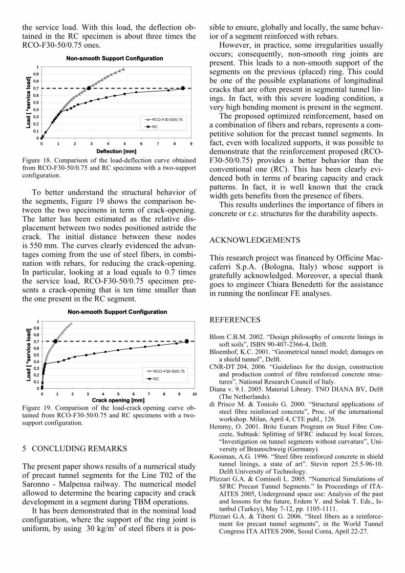
The results of a very severe non-smooth support configuration are presented herein. In particular, the two supports were localized at the ends of the tunnel segment, as shown in Figure 17, acting on a surface of about 300 x 300 mm2 each ones.
Moreover, this boundary conditions have been maintained during all the thrust phase. This assump-tion implies that no further supports could arise in the middle of the segment where the deflection is maximum.
deflection
Figure 17. Non-smooth support configuration adopted for the central precast tunnel segment of the invert.
According to these very restrictive hypothesis,
the rebars in the two chords have been designed in order to guarantee, in the assumed severe condition, a sufficient bending strength under service loads.
The finite element model is the same described in the previous nominal load configuration. The basic hypothesis is that the non-smooth support configura-tion occurs only in the analyzed segment (the central one).
Figure 18 shows the numerical results in terms of load (from the three actuators of the central seg-ment) compared to the deflection measured in the mid-span of the segment. Specimen with optimized reinforcement reaches an ultimate load approxi-mately equal to the service load, as expected from the reinforcement design. On the contrary, the con-ventional RC specimen is able to carry only 70% of
the service load. With this load, the deflection ob-tained in the RC specimen is about three times the RCO-F30-50/0.75 ones.
Non-smooth Support Configuration
0
0,1
0,2
0,3
0,4
0,5
0,6
0,7
0,8
0,9
1
0 1 2 3 4 5 6 7 8 9
Deflection [mm]
Load
[ *s
ervi
ce lo
ad]
RCO-F30-50/0.75
RC
Non-smooth Support Configuration
0
0,1
0,2
0,3
0,4
0,5
0,6
0,7
0,8
0,9
1
0 1 2 3 4 5 6 7 8 9
Deflection [mm]
Load
[ *s
ervi
ce lo
ad]
RCO-F30-50/0.75
RC
Figure 18. Comparison of the load-deflection curve obtained from RCO-F30-50/0.75 and RC specimens with a two-support configuration.
To better understand the structural behavior of
the segments, Figure 19 shows the comparison be-tween the two specimens in term of crack-opening. The latter has been estimated as the relative dis-placement between two nodes positioned astride the crack. The initial distance between these nodes is 550 mm. The curves clearly evidenced the advan-tages coming from the use of steel fibers, in combi-nation with rebars, for reducing the crack-opening. In particular, looking at a load equals to 0.7 times the service load, RCO-F30-50/0.75 specimen pre-sents a crack-opening that is ten time smaller than the one present in the RC segment.
Non-smooth Support Configuration
0
0,1
0,2
0,3
0,4
0,5
0,6
0,7
0,8
0,9
1
0 1 2 3 4 5 6 7 8 9 10
Crack opening [mm]
Load
[ *s
ervi
ce lo
ad]
RCO-F30-50/0.75
RC
Non-smooth Support Configuration
0
0,1
0,2
0,3
0,4
0,5
0,6
0,7
0,8
0,9
1
0 1 2 3 4 5 6 7 8 9 10
Crack opening [mm]
Load
[ *s
ervi
ce lo
ad]
RCO-F30-50/0.75
RC
Figure 19. Comparison of the load-crack opening curve ob-tained from RCO-F30-50/0.75 and RC specimens with a two-support configuration.
5 CONCLUDING REMARKS The present paper shows results of a numerical study of precast tunnel segments for the Line T02 of the Saronno - Malpensa railway. The numerical model allowed to determine the bearing capacity and crack development in a segment during TBM operations.
It has been demonstrated that in the nominal load configuration, where the support of the ring joint is uniform, by using 30 kg/m3 of steel fibers it is pos-
sible to ensure, globally and locally, the same behav-ior of a segment reinforced with rebars.
However, in practice, some irregularities usually occurs; consequently, non-smooth ring joints are present. This leads to a non-smooth support of the segments on the previous (placed) ring. This could be one of the possible explanations of longitudinal cracks that are often present in segmental tunnel lin-ings. In fact, with this severe loading condition, a very high bending moment is present in the segment.
The proposed optimized reinforcement, based on a combination of fibers and rebars, represents a com-petitive solution for the precast tunnel segments. In fact, even with localized supports, it was possible to demonstrate that the reinforcement proposed (RCO-F30-50/0.75) provides a better behavior than the conventional one (RC). This has been clearly evi-denced both in terms of bearing capacity and crack patterns. In fact, it is well known that the crack width gets benefits from the presence of fibers.
This results underlines the importance of fibers in concrete or r.c. structures for the durability aspects.
ACKNOWLEDGEMENTS
This research project was financed by Officine Mac-caferri S.p.A. (Bologna, Italy) whose support is gratefully acknowledged. Moreover, a special thank goes to engineer Chiara Benedetti for the assistance in running the nonlinear FE analyses.
REFERENCES
Blom C.B.M. 2002. “Design philosophy of concrete linings in soft soils”, ISBN 90-407-2366-4, Delft.
Bloemhof, K.C. 2001. “Geometrical tunnel model; damages on a shield tunnel”, Delft.
CNR-DT 204, 2006. “Guidelines for the design, construction and production control of fibre reinforced concrete struc-tures”, National Research Council of Italy.
Diana v. 9.1. 2005. Material Library. TNO DIANA BV, Delft (The Netherlands).
di Prisco M. & Toniolo G. 2000. “Structural applications of steel fibre reinforced concrete”, Proc. of the international workshop. Milan, April 4, CTE publ., 126.
Hemmy, O. 2001. Brite Euram Program on Steel Fibre Con-crete, Subtask: Splitting of SFRC induced by local forces, “Investigation on tunnel segments without curvature”, Uni-versity of Braunschweig (Germany).
Kooiman, A.G. 1996. “Steel fibre reinforced concrete in shield tunnel linings, a state of art”. Stevin report 25.5-96-10. Delft University of Technology.
Plizzari G.A. & Cominoli L. 2005. “Numerical Simulations of SFRC Precast Tunnel Segments.” In Proceedings of ITA-AITES 2005, Underground space use: Analysis of the past and lessons for the future, Erdem Y. and Solak T. Eds., Is-tanbul (Turkey), May 7-12, pp. 1105-1111.
Plizzari G.A. & Tiberti G. 2006. “Steel fibers as a reinforce-ment for precast tunnel segments”, in the World Tunnel Congress ITA AITES 2006, Seoul Corea, April 22-27.
Roelfstra, P.E. & Wittmann, F. H. 1986. “Numerical method to link strain softening with failure of concrete”. In Fracture Toughness and Fracture Energy of Concrete, Wittmann F.H. Ed., Elsevier, Amsterdam, 163-175.
Schnütgen B. 2003. “Design of Precast Steel Fibre Reinforced Tunnel Elements”, in “Test and Design Methods for Steel Fibre Reinforced Concrete - Background and Experiences”, Proc. of the RILEM TC 162-TDF Workshop, Bochum (Germany), March 20-21, 145-152.
Selby, R. G., and Vecchio, F. J. 1993. “Three-dimensional Constitutive Relations for Reinforced Concrete”. Tech. Rep. 93-02, Univ. Toronto, Civil Eng., Toronto, Canada.
Thorenfeldt, E., Tomaszewicz, A., and Jensen, J. J. 1987. “Me-chanical properties of high-strength concrete and applica-tions in design”. In Proc. Symp. Utilization of High-Strength Concrete (Stavanger, Norway).
UNI 11039. 2003. Steel fibre reinforced concrete - Part I: Defi-nitions, classification specification and conformity - Part II: Test method for measuring first crack strength and ductility indexes. Italian Board for Standardization (UNI).
Waal R.G.A. de. 1999. “Steel fibre reinforced tunnel seg-ments”, Delft, ISBN 90-407-1965-9, Delft.