Embed Size (px)
Citation preview
http://www.iaeme.com/IJCIET/index.asp 380 [email protected]
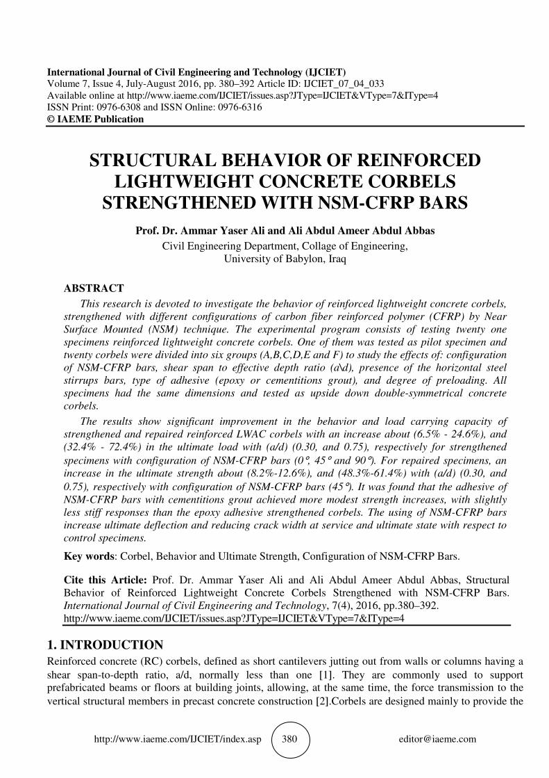
International Journal of Civil Engineering and Technology (IJCIET) Volume 7, Issue 4, July-August 2016, pp. 380–392 Article ID: IJCIET_07_04_033 Available online at http://www.iaeme.com/IJCIET/issues.asp?JType=IJCIET&VType=7&IType=4 ISSN Print: 0976-6308 and ISSN Online: 0976-6316 © IAEME Publication
STRUCTURAL BEHAVIOR OF REINFORCED
LIGHTWEIGHT CONCRETE CORBELS
STRENGTHENED WITH NSM-CFRP BARS
Prof. Dr. Ammar Yaser Ali and Ali Abdul Ameer Abdul Abbas
Civil Engineering Department, Collage of Engineering, University of Babylon, Iraq
ABSTRACT
This research is devoted to investigate the behavior of reinforced lightweight concrete corbels,
strengthened with different configurations of carbon fiber reinforced polymer (CFRP) by Near
Surface Mounted (NSM) technique. The experimental program consists of testing twenty one
specimens reinforced lightweight concrete corbels. One of them was tested as pilot specimen and
twenty corbels were divided into six groups (A,B,C,D,E and F) to study the effects of: configuration
of NSM-CFRP bars, shear span to effective depth ratio (a\d), presence of the horizontal steel
stirrups bars, type of adhesive (epoxy or cementitions grout), and degree of preloading. All
specimens had the same dimensions and tested as upside down double-symmetrical concrete
corbels.
The results show significant improvement in the behavior and load carrying capacity of
strengthened and repaired reinforced LWAC corbels with an increase about (6.5% - 24.6%), and
(32.4% - 72.4%) in the ultimate load with (a/d) (0.30, and 0.75), respectively for strengthened
specimens with configuration of NSM-CFRP bars (0°, 45° and 90°). For repaired specimens, an
increase in the ultimate strength about (8.2%-12.6%), and (48.3%-61.4%) with (a/d) (0.30, and
0.75), respectively with configuration of NSM-CFRP bars (45°). It was found that the adhesive of
NSM-CFRP bars with cementitions grout achieved more modest strength increases, with slightly
less stiff responses than the epoxy adhesive strengthened corbels. The using of NSM-CFRP bars
increase ultimate deflection and reducing crack width at service and ultimate state with respect to
control specimens.
Key words: Corbel, Behavior and Ultimate Strength, Configuration of NSM-CFRP Bars.
Cite this Article: Prof. Dr. Ammar Yaser Ali and Ali Abdul Ameer Abdul Abbas, Structural Behavior of Reinforced Lightweight Concrete Corbels Strengthened with NSM-CFRP Bars. International Journal of Civil Engineering and Technology, 7(4), 2016, pp.380–392. http://www.iaeme.com/IJCIET/issues.asp?JType=IJCIET&VType=7&IType=4
1. INTRODUCTION
Reinforced concrete (RC) corbels, defined as short cantilevers jutting out from walls or columns having a
shear span-to-depth ratio, a/d, normally less than one [1]. They are commonly used to support prefabricated beams or floors at building joints, allowing, at the same time, the force transmission to the
vertical structural members in precast concrete construction [2].Corbels are designed mainly to provide the
Structural Behavior of Reinforced Lightweight Concrete Corbels Strengthened
http://www.iaeme.com/IJCIET/index.asp
vertical reaction Vu at the end of a supported beam, but unless special precautions are taken tohorizontal forces caused by restrained shrinkage, creep, or temperature change, they must also resist a
horizontal force Nu [3]. Owing to their geometric proportions, corbels are commonly classified as a discontinuity region (D-region), where the strain distribution over their of testing twenty one reinforced Contains un-strengthened specimens. NSM-CFRP bars. While in group(C) specimens are strengthened bars (inclined and vertical technique
strength is predominantly controlled by shear rather than flexure
FRP materials are used for repairing or strengthening concrete structures by using Near Surface Mounted (NSM) method, that is now rife as a favorable technology for improving the
of the revoked reinforced concrete members
2. EXPERIMENTAL PROGRAM
The experimental work consisting ofinto six groups. Group (A) contains strengthened with horizontal techniquewith two configurations of NSM-CFRP bars (inclined and vertical technique).are focuses on studying the effect of presence ofstrengthened with two configurations ofadhesives was cement based grout (Sika Groutspecimens with NSM-CFRP bars.cantilevering on opposite side was cantilever projection length of 350150mm at the free end, and the effective depth 2reinforced with four deformed bars having a 16mm diameter and stirrups having a 6mm diameter placed at pitch of 100mm. The primary reinforcement (main bars)top of the corbel with an effective cover of diameter , near the end of each corbels, to provide additional anchorage. The horizontal closed stirrup having diameter 6mm of steel bars.
Figure 1 Details of
f Reinforced Lightweight Concrete Corbels Strengthened
http://www.iaeme.com/IJCIET/index.asp 381
at the end of a supported beam, but unless special precautions are taken tohorizontal forces caused by restrained shrinkage, creep, or temperature change, they must also resist a
Owing to their geometric proportions, corbels are commonly classified as a region), where the strain distribution over their The experimental
LWAC corbels. The corbels are divided into six groups. Group (A) strengthened specimens. Group (B) specimens are strengthened with horizontal
group(C) specimens are strengthened with two configurations oftechnique). Cross section depth is nonlinear, even in the elastic stage, and their
strength is predominantly controlled by shear rather than flexure [4].
FRP materials are used for repairing or strengthening concrete structures by using Near Surface ounted (NSM) method, that is now rife as a favorable technology for improving the
of the revoked reinforced concrete members [5].
EXPERIMENTAL PROGRAM
The experimental work consisting of testing twenty one reinforced LWAC corbels. The corbels are divided contains un-strengthened specimens. While in group (B) specimens are
strengthened with horizontal technique of NSM-CFRP bars. The group(C) specimens are strengthened CFRP bars (inclined and vertical technique).
focuses on studying the effect of presence of horizontal steel stirrups. While in the strengthened with two configurations of NSM-CFRP bars horizontal and inclined
cement based grout (Sika Grout-214). The last group (F)CFRP bars. As shown in Figure (1), the column supporting the two corbels
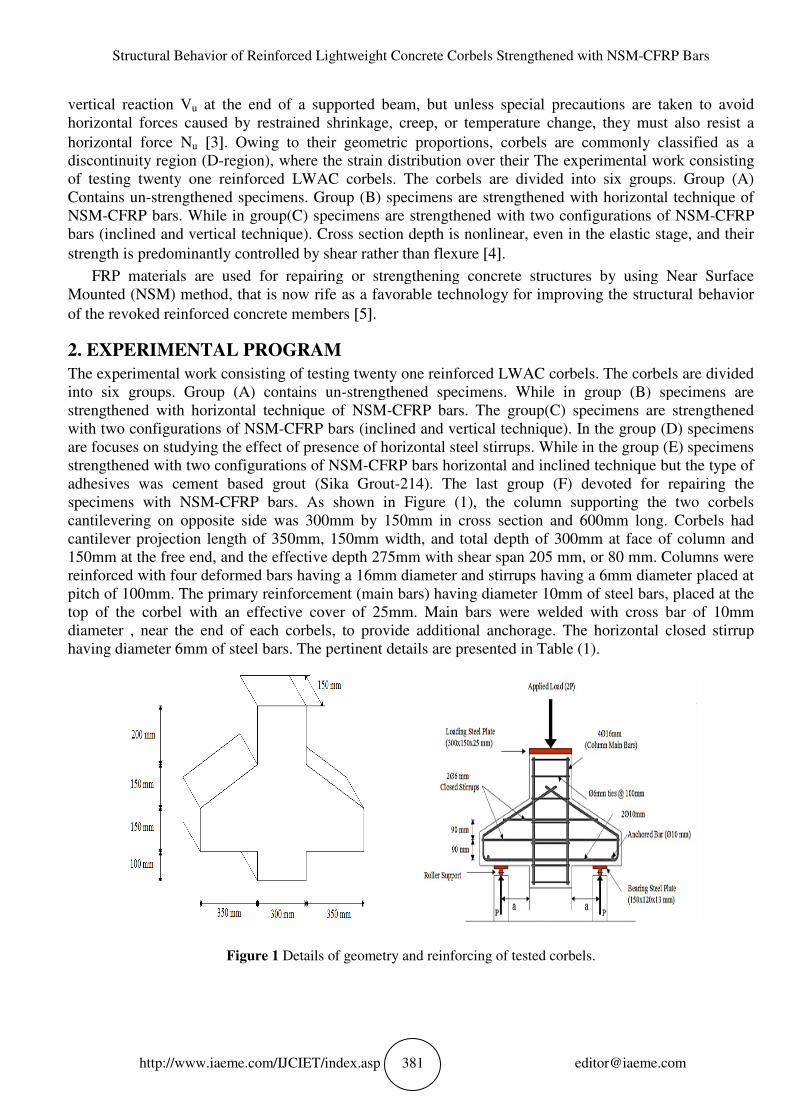
cantilevering on opposite side was 300mm by 150mm in cross section and 50mm, 150mm width, and total depth of 300
150mm at the free end, and the effective depth 275mm with shear span 205 mm, or 80 mm. Columns were reinforced with four deformed bars having a 16mm diameter and stirrups having a 6mm diameter placed at
mm. The primary reinforcement (main bars) having diameter 10mm of steel bars, placed at the top of the corbel with an effective cover of 25mm. Main bars were welded with cross bar of diameter , near the end of each corbels, to provide additional anchorage. The horizontal closed stirrup
ng diameter 6mm of steel bars. The pertinent details are presented in Table
Details of geometry and reinforcing of tested corbels
f Reinforced Lightweight Concrete Corbels Strengthened with NSM-CFRP Bars
at the end of a supported beam, but unless special precautions are taken to avoid horizontal forces caused by restrained shrinkage, creep, or temperature change, they must also resist a
Owing to their geometric proportions, corbels are commonly classified as a The experimental work consisting
d into six groups. Group (A) roup (B) specimens are strengthened with horizontal technique of
with two configurations of NSM-CFRP section depth is nonlinear, even in the elastic stage, and their
FRP materials are used for repairing or strengthening concrete structures by using Near Surface ounted (NSM) method, that is now rife as a favorable technology for improving the structural behavior
testing twenty one reinforced LWAC corbels. The corbels are divided strengthened specimens. While in group (B) specimens are
rs. The group(C) specimens are strengthened In the group (D) specimens
hile in the group (E) specimens inclined technique but the type of
(F) devoted for repairing the As shown in Figure (1), the column supporting the two corbels
mm in cross section and 600mm long. Corbels had 300mm at face of column and mm, or 80 mm. Columns were
reinforced with four deformed bars having a 16mm diameter and stirrups having a 6mm diameter placed at mm of steel bars, placed at the
mm. Main bars were welded with cross bar of 10mm diameter , near the end of each corbels, to provide additional anchorage. The horizontal closed stirrup
ails are presented in Table (1).
of tested corbels.
Prof. Dr. Ammar Yaser Ali and Ali Abdul Ameer Abdul Abbas
http://www.iaeme.com/IJCIET/index.asp
Strengthened schemes were chosen carefully based on the practical needs and the field conditions, crack pattern and practical applied in the actual and economic. In this work, twelve corbels were strengthened with NSM-CFRP bars and four corbels were repair(0.30, and 0.75). For the strengthened and repaired corbels, square grooves
sides of corbel to allow the placement of the CFRP bars (The type of adhesive system used for bonding the NSMall strengthened Groups except strengthened schemes is shown in Figure (2).
Prof. Dr. Ammar Yaser Ali and Ali Abdul Ameer Abdul Abbas
http://www.iaeme.com/IJCIET/index.asp 382
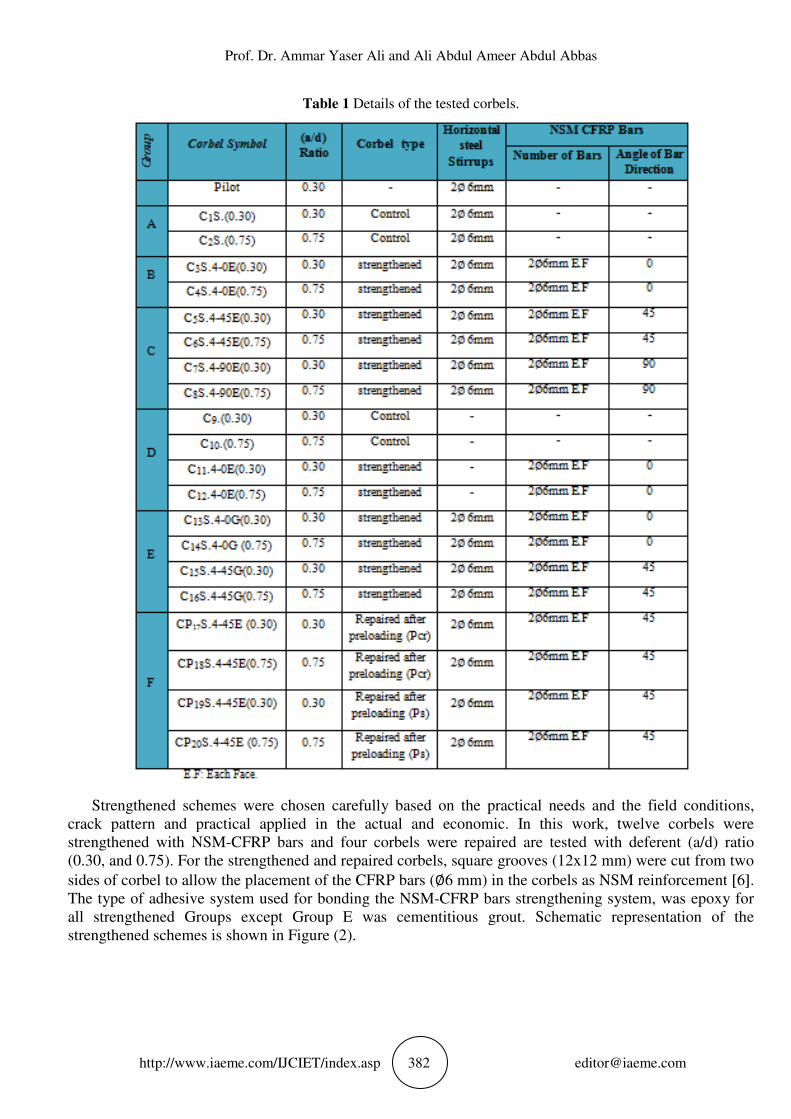
Table 1 Details of the tested corbels.
Strengthened schemes were chosen carefully based on the practical needs and the field conditions, crack pattern and practical applied in the actual and economic. In this work, twelve corbels were
CFRP bars and four corbels were repaired are tested with deferent (a/d) ratio (0.30, and 0.75). For the strengthened and repaired corbels, square grooves (12x12 mm
sides of corbel to allow the placement of the CFRP bars (∅6 mm) in the corbels as NSM reinforcementtype of adhesive system used for bonding the NSM-CFRP bars strengthening system, was epoxy
Group E was cementitious grout. Schematic representation of the strengthened schemes is shown in Figure (2).
Prof. Dr. Ammar Yaser Ali and Ali Abdul Ameer Abdul Abbas
Strengthened schemes were chosen carefully based on the practical needs and the field conditions, crack pattern and practical applied in the actual and economic. In this work, twelve corbels were
ed are tested with deferent (a/d) ratio 12x12 mm) were cut from two
6 mm) in the corbels as NSM reinforcement [6]. CFRP bars strengthening system, was epoxy for
Group E was cementitious grout. Schematic representation of the
Structural Behavior of Reinforced Lightweight Concrete Corbels Strengthened
http://www.iaeme.com/IJCIET/index.asp
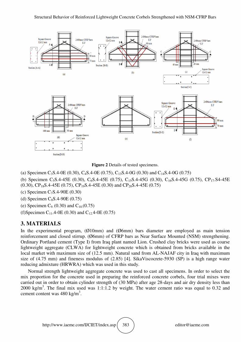
(a) Specimen C3S.4-0E (0.30), C4S.4
(b) Specimen C5S.4-45E (0.30), C(0.30), CP18S.4-45E (0.75), CP19S.4
(c) Specimen C7S.4-90E (0.30)
(d) Specimen C8S.4-90E (0.75)
(e) Specimen C9. (0.30) and C10.(0.75)
(f)Specimen C11.4-0E (0.30) and C
3. MATERIALS
In the experimental program, (Ø10mm) and (Ø6mm) bars diameter are employed as main tension reinforcement and closed stirrup. Ordinary Portland cement (Type I) from Iraq plant namedlightweight aggregate (CLWA) for lightweight concrete which is obtained from bricks available in the local market with maximum size of (size of (4.75 mm) and fineness modulus of (2.reducing admixture (HRWRA) which was used in this study
Normal strength lightweight aggregate mix proportion for the concrete used in preparing the reinforced concrete corbels, carried out in order to obtain cylinder strength of (2000 kg/m3. The final mix used was 1:1:cement content was 480 kg/m3.
f Reinforced Lightweight Concrete Corbels Strengthened
http://www.iaeme.com/IJCIET/index.asp 383
Figure 2 Details of tested specimens.
S.4-0E (0.75), C13S.4-0G (0.30) and C14S.4-0G
(0.30), C6S.4-45E (0.75), C15S.4-45G (0.30), C16S.4S.4-45E (0.30) and CP20S.4-45E (0.75)
(0.75)
and C12.4-0E (0.75)
In the experimental program, (Ø10mm) and (Ø6mm) bars diameter are employed as main tension reinforcement and closed stirrup. (Ø6mm) of CFRP bars as Near Surface Mounted (NSM) strengthening.
ortland cement (Type I) from Iraq plant named Lion. Crushed clay bricks were used as coarse lightweight aggregate (CLWA) for lightweight concrete which is obtained from bricks available in the local market with maximum size of (12.5 mm). Natural sand from AL-NAJAF city in Iraq with maximum
d fineness modulus of (2.85) [4]. SikaViscocrete-5930 (SP) is a high range water reducing admixture (HRWRA) which was used in this study.
lightweight aggregate concrete was used to cast all specimens. In order to select the mix proportion for the concrete used in preparing the reinforced concrete corbels, carried out in order to obtain cylinder strength of (30 MPa) after age 28-days and air
The final mix used was 1:1:1.2 by weight. The water cement ratio was equal to 0.
f Reinforced Lightweight Concrete Corbels Strengthened with NSM-CFRP Bars
0G (0.75)
S.4-45G (0.75), CP17.S4-45E
In the experimental program, (Ø10mm) and (Ø6mm) bars diameter are employed as main tension Mounted (NSM) strengthening.
hed clay bricks were used as coarse lightweight aggregate (CLWA) for lightweight concrete which is obtained from bricks available in the
NAJAF city in Iraq with maximum 5930 (SP) is a high range water
concrete was used to cast all specimens. In order to select the mix proportion for the concrete used in preparing the reinforced concrete corbels, four trial mixes were
and air dry density less than by weight. The water cement ratio was equal to 0.32 and
Prof. Dr. Ammar Yaser Ali and Ali Abdul Ameer Abdul Abbas
http://www.iaeme.com/IJCIET/index.asp 384 [email protected]
4. TEST MEASUREMENT AND INSTRUMENTATION
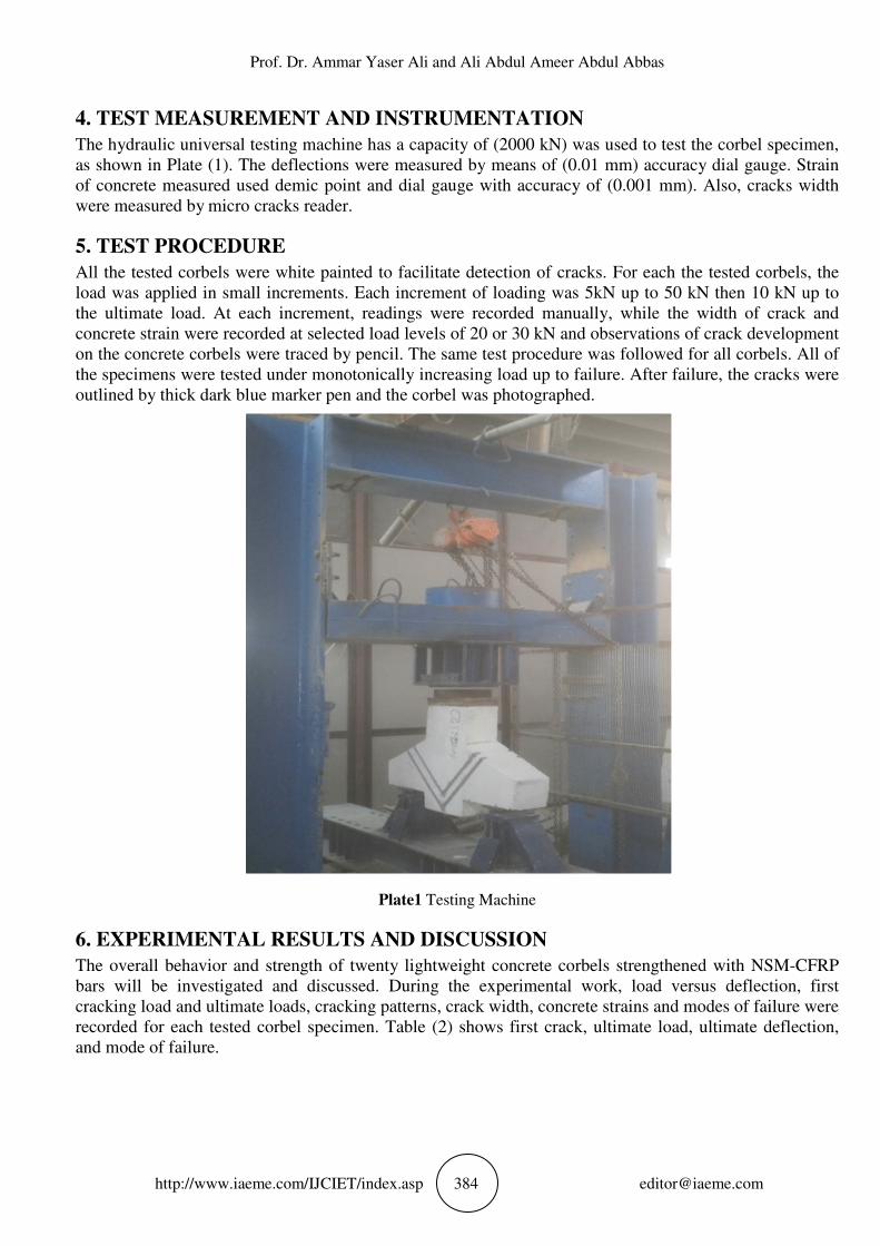
The hydraulic universal testing machine has a capacity of (2000 kN) was used to test the corbel specimen, as shown in Plate (1). The deflections were measured by means of (0.01 mm) accuracy dial gauge. Strain of concrete measured used demic point and dial gauge with accuracy of (0.001 mm). Also, cracks width were measured by micro cracks reader.
5. TEST PROCEDURE
All the tested corbels were white painted to facilitate detection of cracks. For each the tested corbels, the load was applied in small increments. Each increment of loading was 5kN up to 50 kN then 10 kN up to the ultimate load. At each increment, readings were recorded manually, while the width of crack and concrete strain were recorded at selected load levels of 20 or 30 kN and observations of crack development on the concrete corbels were traced by pencil. The same test procedure was followed for all corbels. All of the specimens were tested under monotonically increasing load up to failure. After failure, the cracks were outlined by thick dark blue marker pen and the corbel was photographed.
Plate1 Testing Machine
6. EXPERIMENTAL RESULTS AND DISCUSSION
The overall behavior and strength of twenty lightweight concrete corbels strengthened with NSM-CFRP bars will be investigated and discussed. During the experimental work, load versus deflection, first cracking load and ultimate loads, cracking patterns, crack width, concrete strains and modes of failure were recorded for each tested corbel specimen. Table (2) shows first crack, ultimate load, ultimate deflection, and mode of failure.
Structural Behavior of Reinforced Lightweight Concrete Corbels Strengthened
http://www.iaeme.com/IJCIET/index.asp
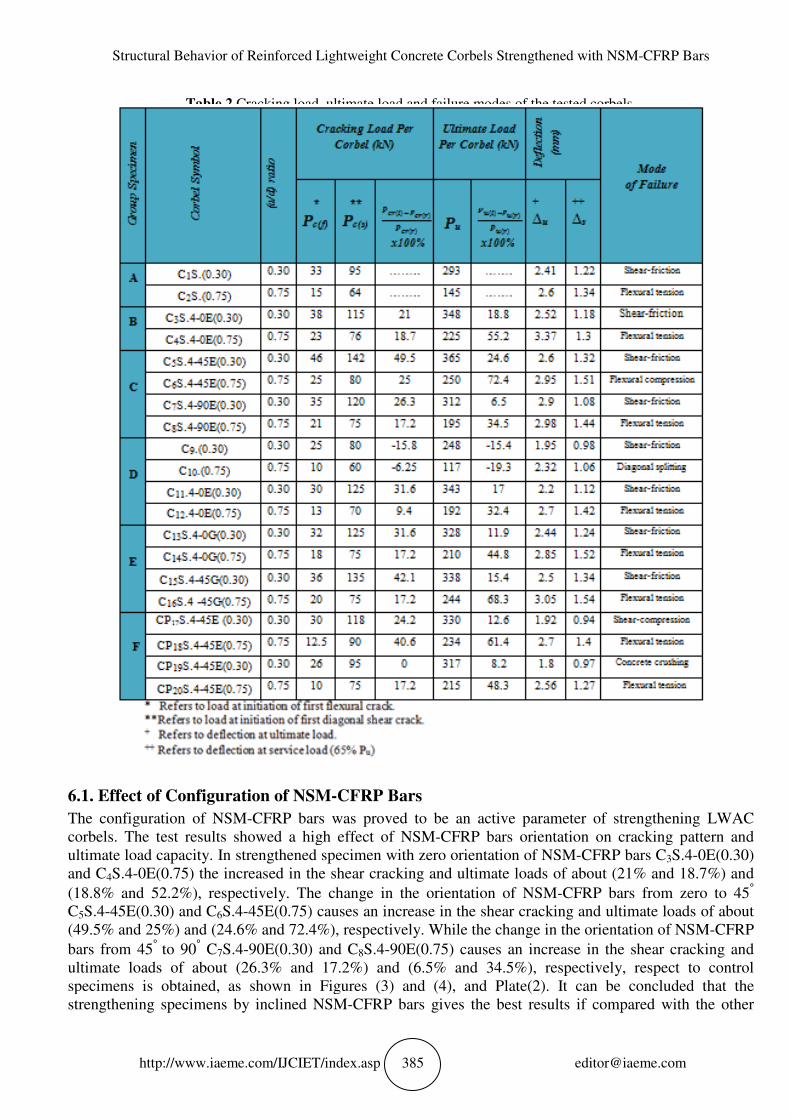
Table 2 Cracking load, ultimate load and failure modes of the tested corbels
6.1. Effect of Configuration of NSM
The configuration of NSM-CFRP barscorbels. The test results showed a high effect of NSMultimate load capacity. In strengthened specimen with zero orientaand C4S.4-0E(0.75) the increased in the shear cracking and ultimate loads of about (21% and 18.7%) and
(18.8% and 52.2%), respectively. The change in the orientation ofC5S.4-45E(0.30) and C6S.4-45E(0.75) causes an (49.5% and 25%) and (24.6% and 72.4%), respectively. While the change in the orientation of NSM
bars from 45° to 90° C7S.4-90E(0.30) and Cultimate loads of about (26.3% and 17.2%) and (6.5% and 34.5%), respectively,specimens is obtained, as shown in Figures strengthening specimens by inclined
f Reinforced Lightweight Concrete Corbels Strengthened
http://www.iaeme.com/IJCIET/index.asp 385
Cracking load, ultimate load and failure modes of the tested corbels
Effect of Configuration of NSM-CFRP Bars
CFRP bars was proved to be an active parameter of strengthening LWAC test results showed a high effect of NSM-CFRP bars orientation on cracking
In strengthened specimen with zero orientation of NSM0E(0.75) the increased in the shear cracking and ultimate loads of about (21% and 18.7%) and
(18.8% and 52.2%), respectively. The change in the orientation of NSM-CFRP bars from zero to 4545E(0.75) causes an increase in the shear cracking and ultimate loads of about
(49.5% and 25%) and (24.6% and 72.4%), respectively. While the change in the orientation of NSM
90E(0.30) and C8S.4-90E(0.75) causes an increase in the shear (26.3% and 17.2%) and (6.5% and 34.5%), respectively,
specimens is obtained, as shown in Figures (3) and (4), and Plate(2). It can be concluded that the strengthening specimens by inclined NSM-CFRP bars gives the best results if compared with the other
f Reinforced Lightweight Concrete Corbels Strengthened with NSM-CFRP Bars
Cracking load, ultimate load and failure modes of the tested corbels.
was proved to be an active parameter of strengthening LWAC CFRP bars orientation on cracking pattern and
NSM-CFRP bars C3S.4-0E(0.30) 0E(0.75) the increased in the shear cracking and ultimate loads of about (21% and 18.7%) and
CFRP bars from zero to 45° increase in the shear cracking and ultimate loads of about
(49.5% and 25%) and (24.6% and 72.4%), respectively. While the change in the orientation of NSM-CFRP
causes an increase in the shear cracking and (26.3% and 17.2%) and (6.5% and 34.5%), respectively, respect to control
It can be concluded that the bars gives the best results if compared with the other
Prof. Dr. Ammar Yaser Ali and Ali Abdul Ameer Abdul Abbas
http://www.iaeme.com/IJCIET/index.asp 386 [email protected]
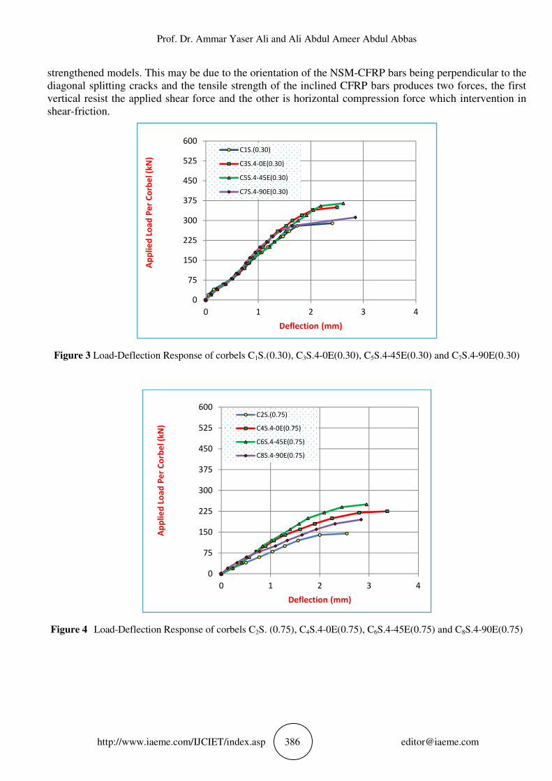
strengthened models. This may be due to the orientation of the NSM-CFRP bars being perpendicular to the diagonal splitting cracks and the tensile strength of the inclined CFRP bars produces two forces, the first vertical resist the applied shear force and the other is horizontal compression force which intervention in shear-friction.
Figure 3 Load-Deflection Response of corbels C1S.(0.30), C3S.4-0E(0.30), C5S.4-45E(0.30) and C7S.4-90E(0.30)
Figure 4s Load-Deflection Response of corbels C2S. (0.75), C4S.4-0E(0.75), C6S.4-45E(0.75) and C8S.4-90E(0.75)
0
75
150
225
300
375
450
525
600
0 1 2 3 4
Ap
pli
ed
Lo
ad
Pe
r C
orb
el
(kN
)
Deflections (mm)
C1S.(0.30)
C3S.4-0E(0.30)
C5S.4-45E(0.30)
C7S.4-90E(0.30)
0
75
150
225
300
375
450
525
600
0 1 2 3 4
Ap
pli
ed
Lo
ad
Pe
r C
orb
el
(kN
)
Deflections (mm)
C2S.(0.75)
C4S.4-0E(0.75)
C6S.4-45E(0.75)
C8S.4-90E(0.75)
Structural Behavior of Reinforced Lightweight Concrete Corbels Strengthened
http://www.iaeme.com/IJCIET/index.asp
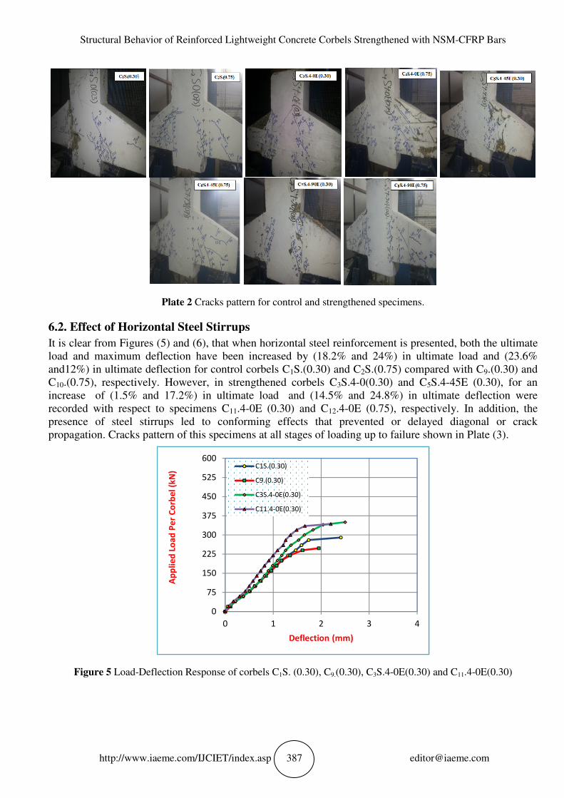
Plate 2 Cracks pattern for control
6.2. Effect of Horizontal Steel Stirrups
It is clear from Figures (5) and (6), that when horizontal steel reinforcement isload and maximum deflection have and12%) in ultimate deflection for control corbels CC10.(0.75), respectively. However, in strengthened corbels Cincreases of (1.5% and 17.2%) in ultimate loadrecorded with respect to specimens Cpresence of steel stirrups led to conformipropagation. Cracks pattern of this specimens
Figure 5 Load-Deflection Response of corbels C
150
225
300
375
450
525
600
Ap
pli
ed
Lo
ad
Pe
r C
orb
el
(kN
)
f Reinforced Lightweight Concrete Corbels Strengthened
http://www.iaeme.com/IJCIET/index.asp 387
Cracks pattern for control and strengthened specimens
Effect of Horizontal Steel Stirrups
), that when horizontal steel reinforcement is load and maximum deflection have been increased by (18.2% and 24%) in ultimate load and (23.6
in ultimate deflection for control corbels C1S.(0.30) and C2S.(0.75) compared with C.(0.75), respectively. However, in strengthened corbels C3S.4-0(0.30) and C
in ultimate loads and (14.5% and 24.8%) in ultimate deflection were recorded with respect to specimens C11.4-0E (0.30) and C12.4-0E (0.75), respectively. In addition, the presence of steel stirrups led to conforming effects that prevented or delayed diagonal or crack
of this specimens at all stages of loading up to failure shown in Plate
Deflection Response of corbels C1S. (0.30), C9.(0.30), C3S.4-0E(0.30) and
0
75
150
225
300
375
450
525
600
0 1 2 3
Deflections (mm)
C1S.(0.30)
C9.(0.30)
C3S.4-0E(0.30)
C11.4-0E(0.30)
f Reinforced Lightweight Concrete Corbels Strengthened with NSM-CFRP Bars
specimens.
presented, both the ultimate in ultimate load and (23.6%
S.(0.75) compared with C9.(0.30) and 0(0.30) and C5S.4-45E (0.30), for an
) in ultimate deflection were (0.75), respectively. In addition, the
ng effects that prevented or delayed diagonal or crack at all stages of loading up to failure shown in Plate (3).
0E(0.30) and C11.4-0E(0.30)
4
Prof. Dr. Ammar Yaser Ali and Ali Abdul Ameer Abdul Abbas
http://www.iaeme.com/IJCIET/index.asp
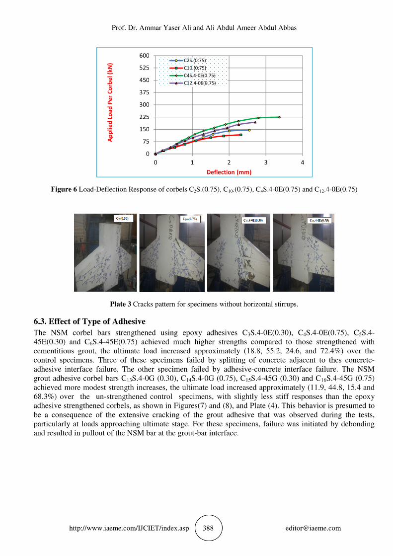
Figure 6 Load-Deflection Response of corbels C
Plate 3 Cracks pattern for specimens without horizontal stirrups
6.3. Effect of Type of Adhesive
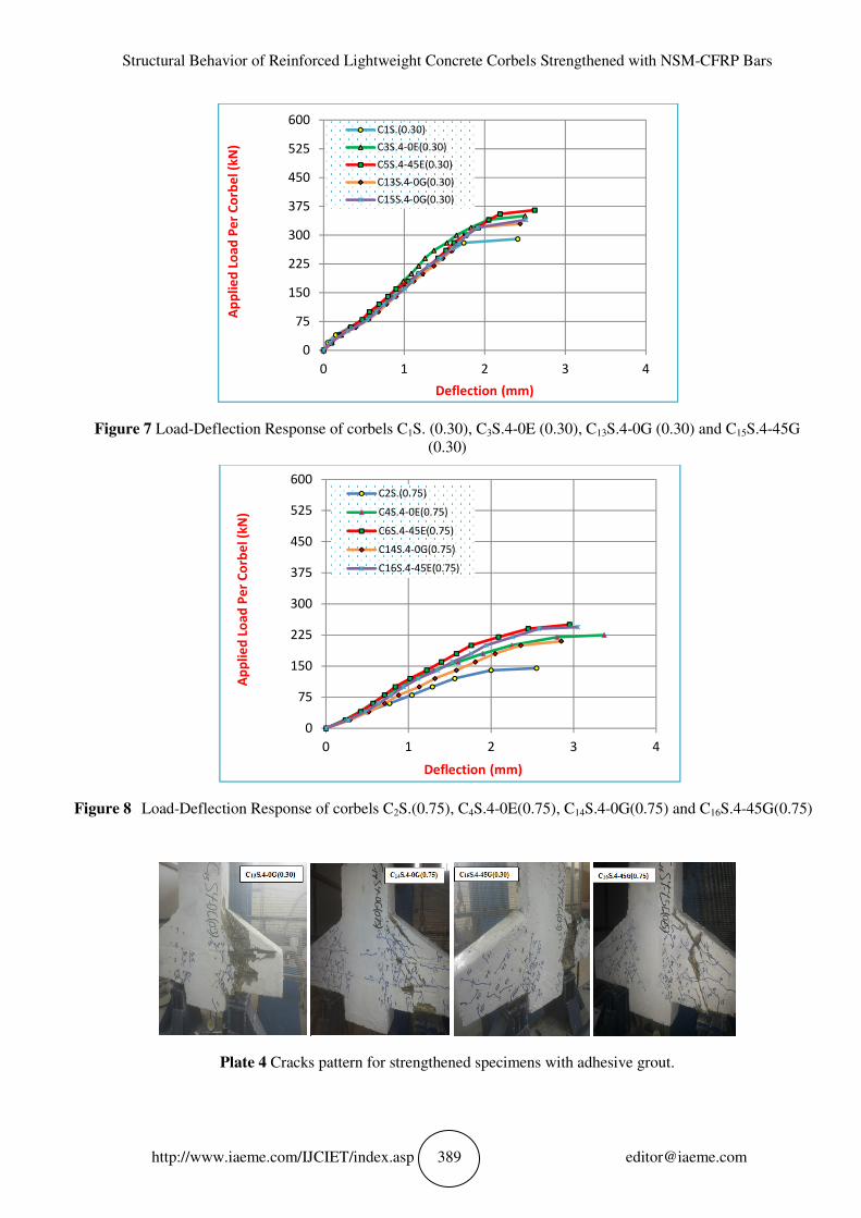
The NSM corbel bars strengthened using epoxy adhesives C45E(0.30) and C6S.4-45E(0.75) achieved much higher strengths compared to those strengthened with cementitious grout, the ultimate load increased approximately (18.8, 55.2, 24.6, and 72.4control specimens. Three of these specimens failed by splitting of concrete adjacent to thes concreteadhesive interface failure. The other specimen grout adhesive corbel bars C13S.4achieved more modest strength increases, the ultimate load increased approximately 68.3%) overs thes un-strengthened controladhesive strengthened corbels, as shown in Figures(be a consequence of the extensive cracking of the grout adhesive that was observed during the testsparticularly at loads approaching ultimate and resulted in pullout of the NSM bar at the grout
150
225
300
375
450
525
600
Ap
pli
ed
Lo
ad
Pe
r C
orb
el
(kN
)
Prof. Dr. Ammar Yaser Ali and Ali Abdul Ameer Abdul Abbas
http://www.iaeme.com/IJCIET/index.asp 388
Deflection Response of corbels C2S.(0.75), C10.(0.75), C4S.4-0E(0.75) and
Cracks pattern for specimens without horizontal stirrups
Type of Adhesive
The NSM corbel bars strengthened using epoxy adhesives C3S.4-0E(0.30),45E(0.75) achieved much higher strengths compared to those strengthened with
the ultimate load increased approximately (18.8, 55.2, 24.6, and 72.4Three of these specimens failed by splitting of concrete adjacent to thes concrete
adhesive interface failure. The other specimen failed by adhesive-concrete interface failure.S.4-0G (0.30), C14S.4-0G (0.75), C15S.4-45G (0.30) and C
achieved more modest strength increases, the ultimate load increased approximately strengthened controls specimens, with slightly less stiff responses than the epoxy
as shown in Figures(7) and (8), and Plate (4). This behavior is presumed to be a consequence of the extensive cracking of the grout adhesive that was observed during the testsparticularly at loads approaching ultimate stage. For these specimens, failure was initiated by debonding and resulted in pullout of the NSM bar at the grout-bar interface.
0
75
150
225
300
375
450
525
600
0 1 2 3
Deflections (mm)
C2S.(0.75)
C10.(0.75)
C4S.4-0E(0.75)
C12.4-0E(0.75)
Prof. Dr. Ammar Yaser Ali and Ali Abdul Ameer Abdul Abbas
0E(0.75) and C12.4-0E(0.75)
Cracks pattern for specimens without horizontal stirrups.
0E(0.30), C4S.4-0E(0.75), C5S.4- 45E(0.75) achieved much higher strengths compared to those strengthened with
the ultimate load increased approximately (18.8, 55.2, 24.6, and 72.4%) over the Three of these specimens failed by splitting of concrete adjacent to thes concrete-
concrete interface failure. The NSM 5G (0.30) and C16S.4-45G (0.75)
achieved more modest strength increases, the ultimate load increased approximately (11.9, 44.8, 15.4 and with slightly less stiff responses than the epoxy
This behavior is presumed to be a consequence of the extensive cracking of the grout adhesive that was observed during the tests,
se specimens, failure was initiated by debonding
4
Structural Behavior of Reinforced Lightweight Concrete Corbels Strengthened
http://www.iaeme.com/IJCIET/index.asp
Figure 7 Load-Deflection Response of corbels C
Figure 8s Load-Deflection Response of corbels C
Plate 4 Cracks pattern for strengthened specimens with adhesive grout
0
75
150
225
300
375
450
525
600
Ap
pli
ed
Lo
ad
Pe
r C
orb
el
(kN
)
0
75
150
225
300
375
450
525
600
Ap
pli
ed
Lo
ad
Pe
r C
orb
el
(kN
)
f Reinforced Lightweight Concrete Corbels Strengthened
http://www.iaeme.com/IJCIET/index.asp 389
Deflection Response of corbels C1S. (0.30), C3S.4-0E (0.30), C13S.4(0.30)
Deflection Response of corbels C2S.(0.75), C4S.4-0E(0.75), C14S.4-0G(0.75) and C
Cracks pattern for strengthened specimens with adhesive grout
0 1 2 3
Deflections (mm)
C1S.(0.30)
C3S.4-0E(0.30)
C5S.4-45E(0.30)
C13S.4-0G(0.30)
C15S.4-0G(0.30)
0
75
150
225
300
375
450
525
600
0 1 2 3
Deflections (mm)
C2S.(0.75)
C4S.4-0E(0.75)
C6S.4-45E(0.75)
C14S.4-0G(0.75)
C16S.4-45E(0.75)
f Reinforced Lightweight Concrete Corbels Strengthened with NSM-CFRP Bars
S.4-0G (0.30) and C15S.4-45G
0G(0.75) and C16S.4-45G(0.75)h
Cracks pattern for strengthened specimens with adhesive grout.
4
4
Prof. Dr. Ammar Yaser Ali and Ali Abdul Ameer Abdul Abbas
http://www.iaeme.com/IJCIET/index.asp 390 [email protected]
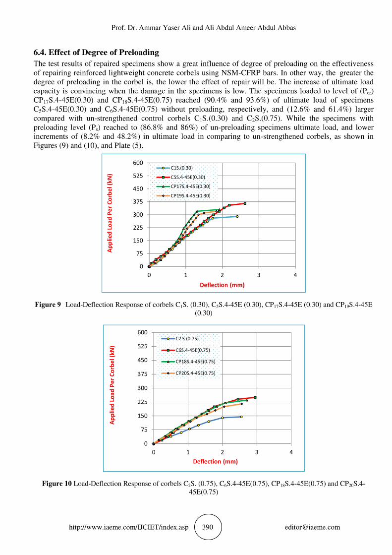
6.4. Effect of Degree of Preloading
The test results of repaired specimens show a great influence of degree of preloading on the effectiveness of repairing reinforced lightweight concrete corbels using NSM-CFRP bars. In other way, thes greater the degree of preloading in the corbel is, the lower the effect of repair will be. The increase of ultimate load capacity is convincing when the damage in the specimens is low. The specimens loaded to level of (Pcr) CP17S.4-45E(0.30) and CP18S.4-45E(0.75) reached (90.4% and 93.6%) of ultimate load of specimens C5S.4-45E(0.30) and C6S.4-45E(0.75) without preloading, respectively, and (12.6% and 61.4%) larger compared with un-strengthened control corbels C1S.(0.30) and C2S.(0.75). While the specimens with preloading level (Ps) reached to (86.8% and 86%) of un-preloading specimens ultimate load, and lower increments of (8.2% and 48.2%) in ultimate load in comparing to un-strengthened corbels, as shown in Figures (9) and (10), and Plate (5).
Figure 9s Load-Deflection Response of corbels C1S. (0.30), C5S.4-45E (0.30), CP17S.4-45E (0.30) and CP19S.4-45E (0.30)
Figure 10 Load-Deflection Response of corbels C2S. (0.75), C6S.4-45E(0.75), CP18S.4-45E(0.75) and CP20S.4-45E(0.75)
0
75
150
225
300
375
450
525
600
0 1 2 3 4
Ap
pli
ed
Lo
ad
Pe
r C
orb
el
(kN
)
Deflections (mm)
C1S.(0.30)
C5S.4-45E(0.30)
CP17S.4-45E(0.30)
CP19S.4-45E(0.30)
0
75
150
225
300
375
450
525
600
0 1 2 3 4
Ap
pli
ed
Lo
ad
Pe
r C
orb
el
(kN
)
Deflections (mm)
C2 S.(0.75)
C6S.4-45E(0.75)
CP18S.4-45E(0.75)
CP20S.4-45E(0.75)
Structural Behavior of Reinforced Lightweight Concrete Corbels Strengthened
http://www.iaeme.com/IJCIET/index.asp
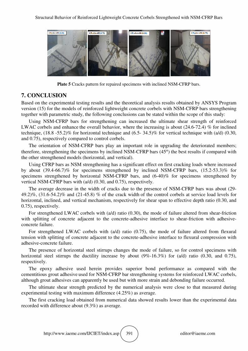
Plate 5 Cracks pattern for repaired specimens with inclined NSM
7. CONCLUSION
Based on the experimental testing results and the theoretical analysis results obtained by ANSYS Program version (15) for the models of reinforced together with parametric study, the following conclusions can be stated within the scope of this study:
Using NSM-CFRP bars for strengthening can increased the ultimate shear strength ofLWAC corbels and enhance the overall behavior, where the increasing is about (24.6technique, (18.8 -55.2)% for horizontal technique and (6.5and 0.75), respectively compared to control corbels.
The orientation of NSM-CFRP bars play an important role in upgrading t
therefore, strengthening the specimens by inclined NSMthe other strengthened models (horizontal, and vertical).
Using CFRP bars as NSM strengthening has a significant effect by about (39.4-66.7)% for specimens strengthened by inclined NSMspecimens strengthened by horizontal NSMvertical NSM-CFRP bars with (a/d) (0.30, and 0.75), respectively.
The average decrease in the width of cracks due to the presence of NSM49.2)%, (31.6-54.2)% and (21-45.8) % of the crack widthhorizontal, inclined, and vertical mechanism, respectively for shear span to effective depth ratio (0.30, and 0.75), respectively.
For strengthened LWAC corbels with (a/d) ratio (0.30), the mode of failure awith splitting of concrete adjacent to the concreteconcrete failure.
For strengthened LWAC corbels with (a/d) ratio (0.75), the mode of failure altered from flexural tension with splitting of concrete adjacent to the concreteadhesive-concrete failure.
The presence of horizontal steel stirrups changes the mode of failure, so for control specimens with horizontal steel stirrups the ductility increase by about (9%respectively.
The epoxy adhesive used herein provides superior bond performancecementitious grout adhesive used for NSMalthough grout adhesives can apparently be used but with more strain and debonding failure occurred.
The ultimate shear strength predicted by the numerical analysis were close to that measured during experimental testing with maximum difference (
The first cracking load obtained from numerical data showed results lower than the experimental data recorded with difference about (9.3
f Reinforced Lightweight Concrete Corbels Strengthened
http://www.iaeme.com/IJCIET/index.asp 391
Cracks pattern for repaired specimens with inclined NSM-CFRP bars
Based on the experimental testing results and the theoretical analysis results obtained by ANSYS Program ) for the models of reinforced lightweight concrete corbels with NSM
he following conclusions can be stated within the scope of this study:
CFRP bars for strengthening can increased the ultimate shear strength ofthe overall behavior, where the increasing is about (24.6
55.2)% for horizontal technique and (6.5- 34.5)% for vertical technique with (a/d) (0.30, and 0.75), respectively compared to control corbels.
CFRP bars play an important role in upgrading t
therefore, strengthening the specimens by inclined NSM-CFRP bars (45°) the best results if compared with the other strengthened models (horizontal, and vertical).
Using CFRP bars as NSM strengthening has a significant effect on first cracking load66.7)% for specimens strengthened by inclined NSM-CFRP bars, (15.2
specimens strengthened by horizontal NSM-CFRP bars, and (6-40)% for specimens strengthened by a/d) (0.30, and 0.75), respectively.
The average decrease in the width of cracks due to the presence of NSM45.8) % of the crack width of the control corbels at service load levels for
horizontal, inclined, and vertical mechanism, respectively for shear span to effective depth ratio (0.30, and
For strengthened LWAC corbels with (a/d) ratio (0.30), the mode of failure awith splitting of concrete adjacent to the concrete-adhesive interface to shear
For strengthened LWAC corbels with (a/d) ratio (0.75), the mode of failure altered from flexural with splitting of concrete adjacent to the concrete-adhesive interface to flexural compression with
The presence of horizontal steel stirrups changes the mode of failure, so for control specimens with irrups the ductility increase by about (9%-16.3%) for (a/d) ratio (0.30, and 0.75),
The epoxy adhesive used herein provides superior bond performanceused for NSM-CFRP bar strengthening systems for reinforced LWAC corbels,
although grout adhesives can apparently be used but with more strain and debonding failure occurred.
The ultimate shear strength predicted by the numerical analysis were close to that measured during sting with maximum difference (4.25%) as average.
The first cracking load obtained from numerical data showed results lower than the experimental data 9.3%) as average.
f Reinforced Lightweight Concrete Corbels Strengthened with NSM-CFRP Bars
CFRP bars.
Based on the experimental testing results and the theoretical analysis results obtained by ANSYS Program NSM-CFRP bars strengthening
he following conclusions can be stated within the scope of this study:
CFRP bars for strengthening can increased the ultimate shear strength of reinforced the overall behavior, where the increasing is about (24.6-72.4) % for inclined
34.5)% for vertical technique with (a/d) (0.30,
CFRP bars play an important role in upgrading the deteriorated members;
) the best results if compared with
on first cracking loads where increased CFRP bars, (15.2-53.3)% for
40)% for specimens strengthened by
The average decrease in the width of cracks due to the presence of NSM-CFRP bars was about (29-control corbels at service load levels for
horizontal, inclined, and vertical mechanism, respectively for shear span to effective depth ratio (0.30, and
For strengthened LWAC corbels with (a/d) ratio (0.30), the mode of failure altered from shear-friction adhesive interface to shear-friction with adhesive-
For strengthened LWAC corbels with (a/d) ratio (0.75), the mode of failure altered from flexural terface to flexural compression with
The presence of horizontal steel stirrups changes the mode of failure, so for control specimens with 16.3%) for (a/d) ratio (0.30, and 0.75),
The epoxy adhesive used herein provides superior bond performance as compared with the ystems for reinforced LWAC corbels,
although grout adhesives can apparently be used but with more strain and debonding failure occurred.
The ultimate shear strength predicted by the numerical analysis were close to that measured during
The first cracking load obtained from numerical data showed results lower than the experimental data
Prof. Dr. Ammar Yaser Ali and Ali Abdul Ameer Abdul Abbas
http://www.iaeme.com/IJCIET/index.asp 392 [email protected]
REFERENCES
[1] ACI Committee 318, Building Code Requirements for Reinforced Concrete and Commentary (ACI 318M - 99/ 318RM - 99), American Concrete Institute, Detroit, 1995.
[2] Aziz, O. Q, Shear Strength Behavior of Crushed Stone Reinforced Concrete Corbels, 26th Conference on Our World in Concrete and Structures, 27-28 August, 2001, Singapore, pp. 767–775.
[3] Kriz, L. B, and Raths, C. H, Connection in Precast Concrete Structural Strength of Corbels, PCI Journal, 10(1), February 1965, pp. 16–61
[4] Kassem, W, 2015, Strength Prediction of Corbels Using Strut-and-Tie Model Analysis, International Journal of Concrete Structures and Materials 9(2), pp.255–266
[5] Tang, W.C., Balendran, R.V, Nadeem, A. and Leung, H.Y, 2005, Flexural Strengthening of Reinforced Lightweight Polystyrene Aggregate Concrete Beams with Near-Surface Mounted GFRP Bars, City University of Hong Kong, China.
[6] ACI Committee 440, 2008, Guide for the Design and Construction of Externally Bonded FRP Systems for Strengthening Concrete Structures (ACI 440.2R-08), ACI Manual of Concrete Practice, American Concrete Institute, Farming Hills, U.S.A.
[7] ASTM C 330-05, 2005, Standard Specification for Lightweight Aggregates for Structural Concrete, Annual Book of ASTM Standards, 4(2) Concrete and Aggregates, West Conshohocken, PA, United States, 4 pp.
[8] Prof. Dr. Ammar Yaser Ali and Ahmed Mohammed Mahdi. Analysis for Behavior And ultimate Strength of Concrete Corbels with Hybrid Reinforcement. International Journal of Civil Engineering and Technology, 6(10), 2015, pp. 25-35.
[9] Shadhan, K. K. and Mohammad Kadhim, M. M. Use of CFRP Laminates for Strengthening of Reinforced Concrete Corbels. International Journal of Civil Engineering and Technology, 6(11), 2015, pp. 11-20.
[10] Asst. Prof. Abdul Ridah Saleh Al-Fatlawi and Ahmed Hadi Hassan, CFRP Strengthening of Circular Concrete Slab with and without Openings, International Journal of Civil Engineering and Technology, 7(1), 2016, pp. 290-303.
[11] Adnan Ibrahim Abdullah, Dr. Muyasser M. Jomaa'h and Dr. Alya'a Abbas Al-Attar, Flexural Behavior of Fiber Reinforced Concrete I- Beams Strengthened With (CFRP), International Journal of Civil Engineering and Technology, 5(1), 2014, pp. 47–60.
[12] Al-Mamoori, F.H, 2015, Structural Behavior of Light Weight Concrete Slab Panels Reinforced with CFRP Bars, Ph.D. Thesis, University of Babylon.