Embed Size (px)
Citation preview

(2006) 183–206www.elsevier.com/locate/enggeo
Engineering Geology 84
Structural and engineering geology of the East Gate Landslide,Purcell Mountains, British Columbia, Canada
Marc-André Brideau a,⁎, Doug Stead a, Réjean Couture b
a Simon Fraser University, Burnaby, BC, Canadab Geological Survey of Canada, Ottawa, ON, Canada
Received 19 July 2005; received in revised form 27 January 2006; accepted 31 January 2006
Abstract
The East Gate Landslide is a prehistoric landslide that was reactivated in January 1997. The slope failure took place in the lowergreenschist metasedimentary units of the Precambrian Horsethief Creek Group. The Grizzly Creek Thrust is a regional overturnedfault that coincides with the location of the headscarp of the East Gate Landslide. Four discontinuity sets were recognised fromdetailed engineering geological mapping of the headscarp and surrounding area. The main scarp of the section reactivated in 1997was sub-divided into three structural domains based on its position within the landslide, lithology, and orientation of thediscontinuity sets. Limit-equilibrium techniques, finite-difference (FLAC) and distinct-element (UDEC) codes were used toinvestigate the failure mechanism of the 1997 event. The results of the field observations and numerical models suggest that the1997 failure involved a complex mechanism incorporating components of rock-slumping, bi-planar, and pseudo-circular failurethat was controlled by both the orientation of the discontinuity sets and reduced rock-mass quality due to tectonic deformation.© 2006 Elsevier B.V. All rights reserved.
Keywords: GSI; Limit-equilibrium; Finite-difference; Distinct-element
1. Introduction
The East Gate Landslide is located on the eastern sideof the Beaver River Valley in Glacier National Park,British Columbia (Fig. 1). The Beaver River Valley isbounded to the east by the Dogtooth Range of thePurcell Mountains and to the west by the Hermit and SirDonald ranges of the Selkirk Mountains. In January1997, an important retrogressive failure took placewithin the rock mass above the oversteepened headscarp (Fig. 2). During the following days and weeks, thelarge intact block slumped down to a few hundredmeters below the head scarp. The rock mass disin-
⁎ Corresponding author.E-mail address: [email protected] (M.-A. Brideau).
0013-7952/$ - see front matter © 2006 Elsevier B.V. All rights reserved.doi:10.1016/j.enggeo.2006.01.004
tegrated completely after less than a few hundred metersof slumping, due to the high degree of fracturing andlow rock-mass quality, and transformed from a debrispile into both debris and mud flows. In both 1999 and2003, mudflows from the upper slope debris impactedthe Trans-Canada Highway (Highway 1), which issituated at the base of the East Gate Landslide (EBAEngineering Consultants Ltd., 2004).
1.1. Previous work
A kinematic analysis performed by Couture andEvans (2000), using joint sets recognised in the head-scarp, suggested toppling as a feasible failure mecha-nism. A pseudo-rotational or rock slumping mechanismwas subsequently proposed as complementary to the

Fig. 1. Location map of the East Gate Landslide in southwestern Canada.
184 M.-A. Brideau et al. / Engineering Geology 84 (2006) 183–206
toppling (Couture and Evans, 2000; EBA EngineeringConsultants Ltd., 2004). Debris is now accumulating atvaried elevations on flatter, bench-like sections of theslope, forming unstable piles of disintegrated rock, inwhich large ripples and open fissures perpendicular tothe flow direction indicate complex movements anddown-slope displacement of debris (Couture and Evans,2002). The benches are assumed to be bedrock-controlled because their continuation is observed outsideof the failure area (Couture and Evans, 2000).
Fig. 2. Overview of the East Gate La
Ground-based monitoring and analysis of high-resolution digital elevation models (DEM) of the debrisindicate significant transfer of materials from the uppersections of the debris mass towards the lowermost part.In addition, the lowermost part of the debris massexhibits high rates of movement, averaging 1m/month(Couture et al., 2004). This section of the debris remainsthe primary source of material that, once combined withrunoff from snowmelt and heavy rainfalls, triggersseasonal debris-flow events that may impact the
ndslide (fall 2003 photograph).

185M.-A. Brideau et al. / Engineering Geology 84 (2006) 183–206
highway. In addition, areas of the main escarpmentshow a large concentration of cracks and opened fissuresthat have opening rates varying from 7 to 603mm/year(Couture et al., 2004). Hence, the debris mass has thepotential to be continuously fed by down-slopemovement of material from the upper parts of thelandslide. Bedrock lineaments were identified in aerialphotographs and in field investigations by previousworkers (Couture and Evans, 2000; EBA EngineeringConsultants Ltd., 2004). A hazard assessment of thecurrent conditions and a review of the mitigative optionswere prepared by EBA Engineering Consultants Ltd.(2004).
1.2. Regional geology
The eastern side of the Beaver River Valley iscomposed of rocks from the late Pre-Cambrian Horse-thief Creek Group (Wheeler, 1963) (Fig. 3). TheHorsethief Creek Group represents a shallowing upwardmegacycle that was deposited during an intracratonicrifting event of the Late Proterozoic (Kubli, 1990). Themetamorphic grade of the Horsethief Creek Group onthe eastern side of the Beaver River Valley corresponds
Fig. 3. Geologic map of the East Gate Landslide (geology m
to the chlorite zone of the lower greenschist facies(Kubli, 1990). The Horsethief Creek Group is sub-divided in a series of slate, grit, and carbonate divisions(Poulton, 1970; Poulton and Simony, 1980; Kubli,1990). The slate divisions are predominantly composedof pelites metamorphosed to slate or phyllite, while thegrit divisions are comprised of weakly metamorphosedgranule or pebble conglomerates. The grit divisions alsocontain a subordinate amount of interbedded laminatedslate and sandstone with rare carbonate horizons (Kubli,1990).
1.3. Structural geology
The Dogtooth Range is composed of a series ofsouthwest-dipping thrust sheets, which form part of animbricate thrust system (Kubli, 1990). In a regionalgeological context, the Dogtooth Range is located on theeastern limb of the northern extension of the PurcellAnticlinorium (Wind, 1967). The rocks on the easternside of the Beaver River Valley have been complexlyfolded, with the bedding (S0) striking north–northwestand dipping to the east. Older thrust faults have beenfolded into a vertical or overturned position (Poulton,
odified from Kubli, 1990; Poulton and Simony, 1980).

186 M.-A. Brideau et al. / Engineering Geology 84 (2006) 183–206
1970). The Grizzly Creek Thrust is a regional over-turned thrust fault mapped by previous geologists(Poulton and Simony, 1980; Kubli, 1990) (Fig. 3). TheGrizzly Creek Thrust fault was first suggested byCouture and Evans (2000) to coincide with the head-scarp of the East Gate Landslide. A pervasive schistosefabric (S1) is present; it was subsequently deformed by acrenulation cleavage (S2) striking northwest to northeastand dipping to the east. The Beaver River Valley followsthe Beaver River Fault, a normal fault that created thePurcell Trench (Wheeler, 1963).
Fig. 4. Attitudes of approximately 1000 discontinuities in the failure scar andpoles to discontinuities and (B) symbolic pole plot of the discontinuity typhemisphere projection, Schmidt nets.
2. Discontinuity sets and structural domains
The attitudes and characteristics of approximately1000discontinuities were recorded at 66stations alongrock exposures in the failure scar and on the ridgeupslope from the East Gate Landslide (Fig. 4).Discontinuity terminology for spacing and persistencefollows the suggested method from the InternationalSociety for Rock Mechanics (ISRM, 1978). Fourdominant discontinuity sets were recognised within thestudy area (Table 1). The dip- and strike-persistence
ridge upslope from the East Gate Landslide. (A) Contoured plot of thees recognized at the East Gate Landslide. Both stereonets are lower

Table 1Summary of discontinuity-set characteristics, East Gate Landslide
Discontinuity set Dip direction Dip Large-scale roughness Small-scale roughness Persistence (m) Spacing (mm)
I–Joint 160°±20° 78°±20° Planar Rough <1 60–200N=145 1–3 200–600II–Joint 260°±30° 82°±20° Planar Rough <1 200–600N=242 1–3 600–2000III–Schistose foliation 010°±20° 20°±10° Planar Smooth <1 20–60N=255 1–3 60–200IV–Crenulation cleavage 154°±10° 30°±20° Stepped Rough <1 20–60N=157 1–3 60–200
187M.-A. Brideau et al. / Engineering Geology 84 (2006) 183–206
estimates of the four discontinuity sets varied betweenvery low persistence (<1m) and low persistence (1–3m). The persistence estimates are believed to represent
Fig. 5. Crenulation cleavage (A) reducing the rock mass quality of micaceousphotographs).
a lower bound due to the two-dimensional nature of theoutcrops and the very blocky structure of the rock mass.The planar and rough discontinuity sets I and II are
phyllite and (B) bounding blocks in quartz rich phyllite (summer 2004

Fig. 6. Structural domains at the head and upslope from the East Gate Landslide. The field stations are represented as dots on the map. Stations outsideof domain boundary are associated with the location of tension cracks and do not include structural measurements.
188 M.-A. Brideau et al. / Engineering Geology 84 (2006) 183–206

189M.-A. Brideau et al. / Engineering Geology 84 (2006) 183–206
steeply dipping and trend parallel and perpendicular,respectively, to the slope. Discontinuity set I has a close(60–200mm) to moderate (200–600mm) spacing,while discontinuity set II has a moderate (200–600mm) to wide (600–2000mm) spacing. The planarand smooth discontinuity set III represents a foliationrelated to the schistose fabric of the phyllite and granuleconglomerate present at the study site. The predomi-nantly stepped and rough discontinuity set IV is relatedto the crenulation cleavage. Fig. 5A illustrates how thecrenulation cleavage significantly reduces the rock-massquality in the micaceous phyllite, whereas Fig. 5Bshows the crenulation cleavage bounding larger blockswithin the quartz-rich phyllite. Both discontinuity setsIII and IV strike obliquely relative to the slope, dippinginto the slope at between 10° and 40°, and arecharacterised by a very close (20–60mm) to close(60–200mm) spacing.
Four structural domains were recognised at the EastGate Landslide (Fig. 6). The structural domains weredivided based on their locations on the landslide(headscarp vs. sidescarp), the variation in lithology,and the attitude of the discontinuity sets (Table 2).Domain 1 encompasses the northern section of the fieldsite, which includes the sidescarp of the recently re-activated area. Domain 1 is composed of quartz-richphyllite with subordinate interbeds of mica-rich phyllite.The second domain is based on measurements acquiredon the ridge 400m behind the present headscarp.
Table 2Summary of structural domains defined at the East Gate Landslide
Domain Position onlandslide
Lithology Attitude ofschistosefoliation(dip→dipdirection)
Averagegeologicalstrengthindex
1 Northernside scarp
Dominantquartz-richphyllite
14°→068° 20–30
Subordinatemica-richphyllite
2 Ridgeupslope fromlandslide
Pebbleconglomerate
24°→281° 20–30
3 Southernside scarp
Dominantmica-richphyllite
27°→003° 10–20
Subordinatequartz-richphyllite
4 Headscarp Quartz- andmica-richphyllite
15°→015° 20–30
Domain 2 is comprised of granule to pebble conglom-erates that are characteristic of the grit divisions of theHorsethief Creek Group. The relative attitude ofdiscontinuity sets I and II is different in domain 2 ascompared to the other domains. Crenulation cleavagewas not obvious in domain 2 outcrops, being replacedby a discontinuity set. Domain 3 encompasses thesouthern sidescarp of the landslide and is characterisedby two very well defined discontinuity sets III and IV.Domain 3 is composed of mica-rich phyllite withsubordinate interbeds of quartz-rich phyllite. The centralsection of the landslide, which includes all of the 1997failure headscarp area, is designated domain 4 and iscomposed of interbeds of quartz-rich and mica-richphyllite.
3. Tension cracks, anti-slope scarps and bedrocklineaments
The locations, orientations and relative lengths oftension cracks, anti-slope (uphill-facing) scarps, andbedrock lineaments recognised at the study area areshown in Fig. 7. A typical tension crack present behindthe southern sidescarp is shown in Fig. 8. A series oftension cracks immediately behind the main escarpmenthas been monitored by the Geological Survey of Canadaand Parks Canada since 2000. The monitored featureswere visited and augmented by the first author with newfeatures recognised during fieldwork performed in thesummer of 2004. EBA Engineering Consultants Ltd.(2004) first reported the presence of anti-slope scarps100m upslope from the headscarp. Some of the anti-slope scarps cut across contour lines. Three groundtraverses from the headscarp to the anti-slope scarpposition were conducted in order to evaluate thepresence of tension cracks or anti-slope scarps. Only afew subdued features were observed along thesetraverses and were included in Fig. 7. The bedrocklineaments were identified from aerial photographs (30BCB 96083 194–196) and have a similar trend to thelithological contacts and regional faulting, and are henceassumed to be the surface expression of these features.
4. Engineering Geology
4.1. Geological strength index (GSI)
The geological strength index (GSI) was developedby Hoek and Brown (1997) to provide a quantitativeevaluation of rock-mass quality for engineering pur-poses. The GSI considers the structure and surfaceconditions of the rock mass (Fig. 9). The spatial

Fig. 8. Example of a tension crack located behind the southern sidescarp (summer 2004 photograph).
Fig. 7. Bedrock lineaments and tension cracks at the East Gate Landslide. Tension cracks were recognised during fieldwork, while bedrock lineamentswere identified from aerial photographs.
190 M.-A. Brideau et al. / Engineering Geology 84 (2006) 183–206
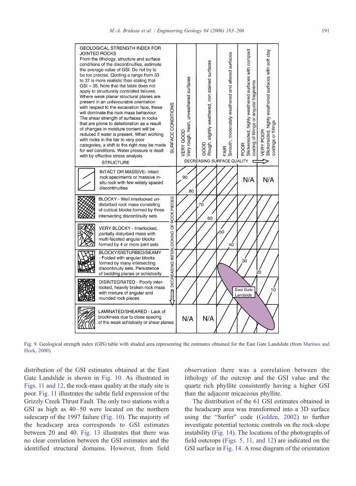
Fig. 9. Geological strength index (GIS) table with shaded area representing the estimates obtained for the East Gate Landslide (from Marinos andHoek, 2000).
191M.-A. Brideau et al. / Engineering Geology 84 (2006) 183–206
distribution of the GSI estimates obtained at the EastGate Landslide is shown in Fig. 10. As illustrated inFigs. 11 and 12, the rock-mass quality at the study site ispoor. Fig. 11 illustrates the subtle field expression of theGrizzly Creek Thrust Fault. The only two stations with aGSI as high as 40–50 were located on the northernsidescarp of the 1997 failure (Fig. 10). The majority ofthe headscarp area corresponds to GSI estimatesbetween 20 and 40. Fig. 13 illustrates that there wasno clear correlation between the GSI estimates and theidentified structural domains. However, from field
observation there was a correlation between thelithology of the outcrop and the GSI value and thequartz rich phyllite consistently having a higher GSIthan the adjacent micaceous phyllite.
The distribution of the 61 GSI estimates obtained inthe headscarp area was transformed into a 3D surfaceusing the “Surfer” code (Golden, 2002) to furtherinvestigate potential tectonic controls on the rock-slopeinstability (Fig. 14). The locations of the photographs offield outcrops (Figs. 5, 11, and 12) are indicated on theGSI surface in Fig. 14. A rose diagram of the orientation

Fig. 10. Spatial distribution of the geological strength index (GSI) estimates for the head for the East Gate Landslide.
192 M.-A. Brideau et al. / Engineering Geology 84 (2006) 183–206
of the discontinuity and tension cracks is provided withthe 3D GSI surface in order to allow comparisonbetween the measured structures and the GSI surface.
4.2. Point-load testing
Point-load tests were undertaken in order to char-acterise the intact strength properties of the differentmaterials present at the East Gate Landslide. The testswere conducted according to the International Societyfor Rock Mechanics (ISRM, 1985) guidelines forirregular blocks. The results of the point load tests are
summarised in Table 3. The unconfined compressivestrength of the different lithologies increases with quartzcontent. These results correspond to the field estimatesthat the mica-rich unit could be easily excavated with arock hammer (12.5–50MPa; “R3-medium strong rock”according to Brown (1981) and Hoek and Brown(1997)) and the quartz-rich units could only be brokenwith a single blow by a rock hammer (50–100MPa;“R4-strong rock”). All the lithologies revealed astrength anisotropy index (Is50perpendicular/Is50parallel;where Is50 is the point load index corrected for the sizeof the sample) between 1.55 and 1.94. This anisotropy is

Fig. 11. Northern sidescarp of the East Gate Landslide. Note the subtle change in GSI values interpreted to represent the field expression of theoverturned Grizzly Creek Thrust (summer 2004 photograph).
193M.-A. Brideau et al. / Engineering Geology 84 (2006) 183–206
attributed to the planes of weakness provided by theschistose foliation of the rocks. According to Fig. 4these planes of weakness dip obliquely into the slope.
4.3. Slake-durability
A series of slake-durability tests was conducted toinvestigate the physical weathering properties due to aseries of wetting and drying cycles of the differentphyllites present at the study area. The rapid break-
down of the failed mass reported by Couture andEvans (2000, 2002) could have been due to thematerial properties of the phyllite or to the closelyspaced discontinuities within the rock mass. Thesamples for the slake-durability tests were collectedfrom the headscarp, talus, mid-section, and depositionareas of the landslide. An attempt was made to collecta wide range of lithological variation. An initial seriesof tests (Coarse A to Phyllite 6B; Table 4) wasconducted following guidelines from the American

Fig. 12. Headscarp of the 1997 slope failure with structural domains represented (summer 2004 photograph).
194 M.-A. Brideau et al. / Engineering Geology 84 (2006) 183–206
Society for Testing and Materials (ASTM, 1987).None of the samples of the initial series of testsexhibited more than 10% disintegration after twocycles of 10min at 20rpm (Id2>0.90) (Table 4).Similar Id2 values were obtained by Ramamurthy et al.(1993) for phyllites from the Himalayan region. Asecond series of tests was performed using four cycles
Fig. 13. Distribution of the GSI estimates as a fu
of 10min at 20rpm, as suggested in an alternateprocedure by Richardson and Long (1987). Samplesfrom this second series of tests again failed to exhibita disintegration of more than 10% (Id4>0.90) (Table4). No relation between the slake durability and eitherthe location on the slope or the lithology of the samplewas observed in either series of tests.
nction of the identified structural domains.

Fig. 14. Three-dimensional GSI surface related to the structural data.
195M.-A. Brideau et al. / Engineering Geology 84 (2006) 183–206
4.4. Kinematic analysis
A kinematic analysis of sliding, toppling, andwedge failure mechanisms was performed on themean of the discontinuity sets identified in domain 4because this domain encompassed the area involvedin the 1997 failure (Fig. 15). A slope attitude of45°→270° (dip→dip direction) and a 30° frictionangle was used in the analysis (Fig. 15A). A very lowfriction angle of 20° was also considered along the
Table 3Point-load test results for different lithologies recognised at the East Gate La
Lithology Point load index(MPa)
Unconfinestrength (
Mica-rich phyllite parallel(average quartz content 25%)
1.59 38
Mica-rich phyllite perpendicular 3.14 59Quartz-rich phyllite parallel
(average quartz content 40%)2.45 54
Quartz-rich phyllite perpendicular 4.77 105Grit parallel (average quartz content 60%) 4.09 90Grit perpendicular 6.36 140
Samples were tested parallel and perpendicular to the schistose fabric.
schistose fabric to assess the sensitivity of the frictionangle because it was described in the field as smoothand planar. Such a low effective frictional strengthcould also be considered to simulate the effect of highpore-water pressures. Toppling along some disconti-nuities of set II is feasible (Fig. 15B). Planar failure isnot feasible with a 30° friction angle and ismarginally possible using a 20° friction angle (Fig.15A). Wedge failures do not appear kinematicallyfeasible (Fig. 15C).
ndslide
d compressiveMPa)
Number samplestested
Number oftests performed
Anisotropyindex
3 7
2 2 1.554 5
3 3 1.942 22 2 1.55

Table 4Results of slake-durability testing
Sample 1 cycle 2 cycles 3 cycles 4 cycles Sample location
Id1 Id2 Id3 Id4
Coarse A 0.993 0.945 Mid-TalusCoarse B 0.991 0.939 Mid-TalusPhyllite 1A 0.969 0.900 Lower-TalusPhyllite 2B 0.986 0.929 Lower-TalusPhyllite 3A 0.970 0.907 Lower-TalusPhyllite 4B 0.987 0.932 Lower-TalusPhyllite 5A 0.967 0.943 Lower-TalusPhyllite 6B 0.981 0.967 Lower-Talus04-25-09-01 0.988 0.981 0.975 0.970 Northern side scarp04-25-12-01 0.987 0.977 0.970 0.963 Northern side scarp04-23-09-01 0.979 0.966 0.953 0.942 Headscarp04-26-05-01 0.982 0.969 0.958 0.948 Headscarp04-23-06-01 0.974 0.956 0.942 0.929 Headscarp04-22-06-02 0.993 0.989 0.985 Southern side scarp04-22-06-01 0.971 0.954 0.937 0.924 Southern side scarp04-28-01-01 0.986 0.976 0.967 0.958 Southern side scarp
196 M.-A. Brideau et al. / Engineering Geology 84 (2006) 183–206
Several difficulties are encountered, however, whenconsidering toppling as the dominant failure mechanismfor the East Gate Landslide. Firstly, the prominent basalsurfaces of the blocks are dipping into the slope withonly a subordinate number of planes dipping down-slope. Secondly, the spacing of the discontinuity sets(Table 1) creates tabular blocks which do not favour ablock toppling mechanism (Wyllie and Mah, 2004).Thirdly, the tension cracks surveyed behind the head-scarp opened (with only two exceptions) on theslumping (cataclinal) discontinuity and not on thetoppling (anaclinal) discontinuity. Fourthly, the ob-served failures since 1997 all have exhibited pseudo-circular slumping topography. Finally, the present-dayheadscarp morphology is controlled by the south-striking and steeply west-dipping (cataclinal) disconti-nuity set II.
Using the discontinuity sets recognised at the EastGate Landslide, and considering both kinematic analysisand field observations, a conceptual 3D block diagram isproposed (Fig. 16). In this model, discontinuity set Iwould facilitate the development of lateral releasesurfaces. The interaction of discontinuity sets II, IIIand/or IV suggests that a rock-slumping (Kieffer, 1998,2003) or active-passive wedge (Coulthard, 1979; Stead,1984) mechanism might be appropriate. Such mechan-isms are further complicated by the presence of theGrizzly Creek Thrust fault which has degraded the rock-mass quality at the base of the unstable mass. In theproposed conceptual model, the toppling (anaclinal)discontinuities are attributed to fault damage associatedwith the overturned Grizzly Creek Thrust.
5. Numerical modelling
The failure mechanism of the 1997 event at the EastGate Landslide was investigated using limit-equilibri-um, finite-difference and distinct-element models. Thelimit-equilibrium model was used as a preliminaryassessment of the dependence of the critical failuregeometry on the strength of the rock mass. The rockmass was assumed of sufficiently low-rock mass quality(as opposed to a weak intact rock mass) to be consideredas an equivalent continuum material. The finitedifference code was used to model the stress–strainrelations within the rock slope. The distinct-elementcode allowed the control exerted by both discretestructures and rock-mass strength to be investigated.The cross section used in all of the models was derivedfrom a pre-1997 detailed topographic map of the EastGate Landslide provided by the Geological Survey ofCanada. The Mohr–Coulomb parameters used for therock mass in the various models were estimated usingRocLab software (RocScience, 2002). Two sets ofproperties were derived. The first set of propertiesrelated to the overall quality of the rock mass observedat the East Gate Landslide (Table 5). The uniaxialcompressive strength (UCS) measured perpendicular tothe foliation for the mica-rich phyllite of 50MPa and aGSI value of 30 were used as input in RocLab. Thesecond set of properties described the intenselydeformed material associated with the Grizzly CreekThrust Fault (Table 5). A reduced GSI value of 15(based on field observation) was used as input inRocLab.

Fig. 16. Conceptual block model of the East Gate Landslide showingthe discontinuity sets and the tectonic structures influencing slopestability.
Fig. 15. Kinematic analysis for the headscarp of the East GateLandslide: (A) planar sliding, (B) toppling, (C) wedge failure.
197M.-A. Brideau et al. / Engineering Geology 84 (2006) 183–206
5.1. Limit-equilibrium modelling
SLIDE by RocScience (2004) is a slope-stabilityprogram that evaluates the stability of circular and non-circular slip surfaces in soil or rock slopes using vertical-slice limit-equilibrium methods. The Spencer (1967)and Morgenstern and Price (1965) analysis methodswere used in the models investigated. These methods arerigorous limit-equilibrium techniques that satisfy bothforce and moment equilibrium. The first series ofmodels investigated circular and non-circular surfacesfor a Mohr–Coulomb material with the cohesion andfriction-angle values for the overall rock mass (Table 5).These models suggested a factor of safety (FOS) of∼1.6
Table 5Material and discontinuity properties used in the numerical models ofthe East Gate Landslide
Overall rock mass Damaged rock mass
MaterialDensity (kg/m3) 2700 2700Bulk modulus (GPa) 1.5 0.66Shear modulus (GPa) 1.0 0.40Cohesion (MPa) 0.25 0.1Tensile strength (MPa) 0 0Friction angle (deg) 45 34
JointNormal stiffness (GPa/m) 4 2Shear stiffness (GPa/m) 2 1Joint cohesion (MPa) 0 0Joint tensile strength (MPa) 0 0Joint friction angle (deg) 20–30 20–30

Fig. 17. Global minimum slip surface of the East Gate Landslideobtained from Spencer's limit-equilibrium method for (A) the overallrock-mass material properties and (B) the damaged-rock-massproperties. The critical slip surface obtained in (B) resembles theactual 1997 slope failure.
Table 6Factor of safety obtained for limit-equilibrium analyses using differentcombinations of material strength properties and “ru” pore-pressurecoefficients
Model Cohesion(kPa)
Frictionangle(deg)
ru Factor of safety(limit-equilibrium)
Factor of safety(strength-reduction)
1 100 34 0 0.93 0.992 160 37 0.1 1.01 –3 200 40 0.2 1.00 –4 250 45 0 1.65 1.675 250 45 0.1 1.45 –6 250 45 0.2 1.22 –7 250 45 0.3 1.01 –
198 M.-A. Brideau et al. / Engineering Geology 84 (2006) 183–206
for both the Spencer and Morgenstern–Price methods(Fig. 17A). The minimum FOS was obtained for a deep-seated movement with a top of the surfacecorresponding with the location of the anti-slope scarps.The damaged rock-mass properties were then investi-gated with respect to their effects on the stability of theslope and on the shape of the minimum circular and non-circular surfaces. For a cohesion value of 0.1MPa and afriction angle of 34°, a circular failure surface of similarshape and cross sectional area to the 1997 failure eventdeveloped for the Spencer and Morgenstern–Pricemethods (Fig. 17B). The models investigated for anon-circular slip surface with the reduced materialproperties had larger volumes than the circular failureand the 1997 event.
Since no constraints were available on the ground-water conditions, its effect on the slope stability wasinvestigated by considering various values for the “ru”
coefficient, which models the pore-water pressure as afraction of the vertical earth pressure for each slice alongthe critical slip surface (“ru”=0 for dry condition and“ru”=1 for artesian pore-water pressure rising aboveground the height of the soil column modeled). For “ru”of 0.3, the factor of safety is 1.0 for overall rock massstrength properties, but the critical slip surface is similarto Fig 17A, which is larger than the observed failuresurface for the 1997 event (Table 6).
5.2. Finite-difference modelling
FLAC is a 2D finite-difference modelling codefrom Itasca (2002a), which models the stress–strainresponse of a continuum material (e.g., soil or rock) toloading (static or dynamic). The advantages of thefinite-difference code over the limit-equilibrium tech-nique are that no failure path needs to be specified andthe elastic and plastic behaviour of the material can beincluded in the analysis. A factor of safety can becomputed using the strength-reduction technique(Dawson et al., 1999) in the FLAC/Slope module(Itasca, 2002b). The factor of safety values obtained inFLAC/Slope for the overall and damage rockproperties (Table 5) of the East Gate Landslidecorrelated with the factors of safety obtained usingthe limit equilibrium method.
The first model investigating the stress–strainbehaviour in the East Gate Landslide using FLAC,modelled the overall rock-mass properties using anelastic–plastic Mohr–Coulomb constitutive criterion(Table 5). The maximum shear strain increment contourplot illustrates a small shear-strain concentration at thebase of the material that failed in 1997 (Fig. 18A). In thesecond model, the elastic–plastic Mohr–Coulombproperties were reduced to reflect the properties of thedamaged rock mass. The maximum shear-strain incre-ment concentration observed in this model was four

Fig. 18. FLAC numerical model of the East Gate Landslide. Maximum shear strain increment contour plots for (A) the overall rock-mass qualityobserved at the site and (B) the damaged-rock-mass quality. Note that the contour intervals are four orders of magnitude larger in (B) than in (A).
199M.-A. Brideau et al. / Engineering Geology 84 (2006) 183–206
orders of magnitude greater than in the overall rockmass and it encompassed a zone only slightly smallerthan the material that failed in 1997 (Fig. 18B).
Models in which a ubiquitous joint was introduced inthe elastic–plastic Mohr–Coulomb constitutive criteriawere also investigated. The overall and damaged rock-

200 M.-A. Brideau et al. / Engineering Geology 84 (2006) 183–206
mass properties listed in Table 5 were investigated withthe addition of a ubiquitous discontinuity set dipping10° into the slope (anaclinal). This discontinuity set
Fig. 19. UDEC numerical models of the East Gate Landslide. Velocity vectodiscontinuities. Plasticity state of the nodes from the model with fault as (C)
represents the intersection of discontinuity sets III(schistose foliation) and IV (crenulation cleavage).The behaviour of the models with and without the
rs for model with fault as (A) single discontinuity, (B) a set of parallelsingle discontinuity and (D) a set of parallel discontinuities.

Fig. 19 (continued).
201M.-A. Brideau et al. / Engineering Geology 84 (2006) 183–206
ubiquitous joint criterion was similar, with the exceptionthat the ubiquitous models developed a wider zone ofelements failing in tension behind the headscarp of theEast Gate Landslide.
5.3. Distinct-element modelling
UDEC is a two-dimensional distinct-element codefrom Itasca (2004) that models the response of a
202 M.-A. Brideau et al. / Engineering Geology 84 (2006) 183–206
discontinuous medium, such as a jointed rock mass, toloading (static or dynamic). The material and disconti-nuity properties used in a series of models are listed inTable 5. The models investigated assumed that theblocks making up the rock mass behaved as an elastic–plastic Mohr–Coulomb material. The schistose foliationwas simulated using the ubiquitous Mohr–Coulombcriteria with an assumed direction of weakness dipping10° into the slope.
Several discontinuity geometries were represented inthe UDEC models. First, the discontinuity set II ana-clinal, discontinuity set II cataclinal, and discontinuityIII (schistose foliation) (Fig. 6) were representedindividually in the models to investigate their influenceon slope movement. Discontinuity set I was notconsidered in the models presented here because it isparallel to the cross section investigated. Discontinuityset I is important, however, because it provides lateralrelease to the blocks. This first series of models foundthat the anaclinal discontinuities (toppling) create anextensive zone of opening and shearing upslope fromthe headscarp of the failure while the model withcataclinal discontinuities (slumping) creates a morelocalised opening and shearing along discontinuitiesupslope from the headscarp. A second series of modelscompared the representation of the Grizzly Creek Faultas a single discontinuity and as a set of paralleldiscontinuities (similar to representation in Fig. 16).Fig. 19A and B show the velocity vectors for the modelwith the fault as a single discontinuity and a set ofparallel discontinuities respectively. Fig. 19B outlinesmore clearly a semi-circular zone of material that isslightly larger than the 1997 failure outline. Fig. 19Cand D represent the plasticity state of the nodescomposing the two models. Fig. 19D outlines a zoneat the toe of the East Gate Landslide where aconcentration of nodes has failed by slip along theubiquitous joints. Also occurring in both models aretensile failures in the nodes behind the headscarp.
6. Discussion
The results of the slake-durability tests suggest thatthe observed rapid breakdown of the failed materialreported by Couture and Evans (2000, 2002) is not amaterial property. It is possible that the apparent lack ofbreakdown indicated by the slake-durability test isrelated to the inability of the testing method to readilysimulate the material's physical weathering due, forexample, to freeze–thaw cycles. Alternatively, the rapidmaterial breakdown at the headscarp of the 1997 failureof the East Gate Landslide may be highly localized and
controlled by tectonic damage due to major structuressuch as the Grizzly Creek Thrust.
The headscarp of the 1997 event is covered by athin film of silt- and clay-size material while the cliffface just 10m away from the headscarp did not havesuch a thin film. This condition was also observedduring fieldwork by the third author in 1999. Silt- andclay-size material appears to have been movedpredominantly by surface runoff on the headscarp. Alocalized source of the fine material could not beobserved directly in the field; however, the ground-water conditions and the influence of groundwater onthe stability of the slope at the East Gate Landslide arenot well known. Field mapping by the first author inAugust 2004 indicated one seepage zone located at thebase of the central section of the headscarp and asecond one at the base of the northern sidescarp. Bothoccurred in micaceous phyllite with very low GSIvalues (0–10), indicating possible structural control.EBA Engineering Consultants Ltd. (2004) also notedgroundwater seepage at the base of the first bench inthe debris material (∼50m from the headscarp). A lowtemperature (approx. −10°C) period preceded warmtemperatures (approx. 0°C) in the days before the1997 landslide. It was suggested that such lowtemperatures would have reduced the permeabilitydue to freezing of the natural conduit. This wouldhave led to high pore-water pressure when thetemperature increased, thereby further reducing thestability of the slope by reducing the effective frictionalong the discontinuity surfaces (EBA EngineeringConsultants Ltd., 2004).
The delineated structural domains suggest that thesouthern sidescarp of the East Gate Landslide hassubsided vertically and rotated counter-clockwise rela-tive to the central and northern sections. This confirmsthe preliminary observation by Couture and Evans(2000) that the southern sidescarp appeared to bedisplaced. Domain 3 is a culmination of a progressivecounter-clockwise rotation of the strike of the discon-tinuity sets from domains 1, 3, and 4. This is furthersupported by field observations that the southern portionof the landslide is bounded by lineaments. Domain 2 isnot considered further here because it is 400m from theother domains and possibly is affected by another faultsystem.
Circular rock-mass and rock-slumping failure inweak highly jointed rock masses has been recognisedin the past in rock cuts and open-pit mines (Sjoberg,2000; Wyllie and Mah, 2004). Couture and Evans(2000) noted that, because of the highly fracturednature of the rock mass at the East Gate Landslide, a

203M.-A. Brideau et al. / Engineering Geology 84 (2006) 183–206
pseudo-circular retrogressive failure may have beenpossible. The proposed conceptual model and theresults from preliminary numerical models appear tosupport a complex rock slumping/bi-planar mechanismthat approaches a circular failure due to the poor rock-mass quality. The geometry used in the numericalanalysis was based on the conceptual model presentedin Fig. 16. The numerical models can be constrainedby the geological structures observed on site. Sheardisplacement along discontinuities in models thatinclude steep slumping (cataclinal) discontinuitymatches agree closely with the location of the tensioncracks immediately behind the main escarpment andof the anti-slope scarps observed in the field. This isin contrast to the discontinuum models that simulatedonly toppling (anaclinal) discontinuities and whichdeveloped extensive zones of extension and shear thatdid not match field observations. The inclusion of theGrizzly Creek Thrust in the numerical models wasshown to have an important effect on the failureoutline, its representation as a set of parallel dis-continuities led to stress concentration in the toe of thelandslide and facilitated slip along the ubiquitous(foliation) discontinuities. The heavily fractured natureof the rock mass introduced two complications in thenumerical models. First, the material propertiesobserved in the field and estimated using RocLabwere at the boundary between a weak rock mass and
Fig. 20. Hillshade obtained from a digital elevation model (DEM) of the Binstabilities and the trace of the Grizzly Creek Thrust.
soil behaviour. Secondly, it was impossible torepresent a discontinuity spacing in the distinct-element model that would be of the same order ofmagnitude as observed in the field. Another limitationof the models presented here is that the 3D nature ofthe failure cannot be accurately represented in the 2Dmodels. Schistose foliation and crenulation cleavagewere represented as one plane dipping 10° into theslope, while in practice they are two distinct planesstriking obliquely with respect to the slope (Fig. 16).Taking into account the effect of groundwater only asa “ru” coefficient in the limit-equilibrium models is anoversimplification of the potential role played by pore-water pressure on rock slope-stability and failuremechanisms. These limitations of the model reduce itscapability to investigate the influence of the 3Dgeometry of discontinuity sets and groundwater on thestability of the slope. However, the good correlationbetween the deformation structures observed in thefield and those simulated in the numerical modelssuggests that the dominant mechanisms operative atthe East Gate Landslide have been realisticallycaptured.
Slope instability along the Beaver River Valley is notrestricted to the East Gate Landslide (Pritchard et al.,1989). Pritchard (1989) suggested that the location oflandslides in the Beaver River Valley was partiallycontrolled by the lithology as they appeared to occur
eaver River Valley showing East Gate Landslide in relation to other
204 M.-A. Brideau et al. / Engineering Geology 84 (2006) 183–206
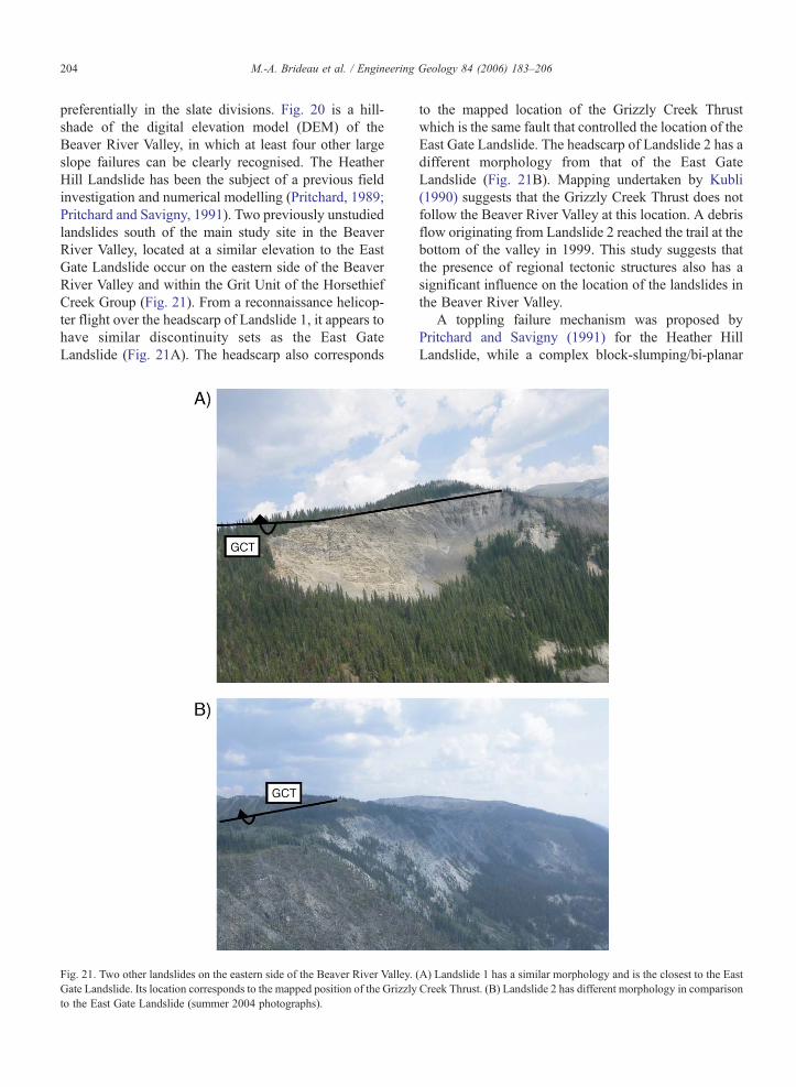
preferentially in the slate divisions. Fig. 20 is a hill-shade of the digital elevation model (DEM) of theBeaver River Valley, in which at least four other largeslope failures can be clearly recognised. The HeatherHill Landslide has been the subject of a previous fieldinvestigation and numerical modelling (Pritchard, 1989;Pritchard and Savigny, 1991). Two previously unstudiedlandslides south of the main study site in the BeaverRiver Valley, located at a similar elevation to the EastGate Landslide occur on the eastern side of the BeaverRiver Valley and within the Grit Unit of the HorsethiefCreek Group (Fig. 21). From a reconnaissance helicop-ter flight over the headscarp of Landslide 1, it appears tohave similar discontinuity sets as the East GateLandslide (Fig. 21A). The headscarp also corresponds
Fig. 21. Two other landslides on the eastern side of the Beaver River Valley.Gate Landslide. Its location corresponds to the mapped position of the Grizzlyto the East Gate Landslide (summer 2004 photographs).
to the mapped location of the Grizzly Creek Thrustwhich is the same fault that controlled the location of theEast Gate Landslide. The headscarp of Landslide 2 has adifferent morphology from that of the East GateLandslide (Fig. 21B). Mapping undertaken by Kubli(1990) suggests that the Grizzly Creek Thrust does notfollow the Beaver River Valley at this location. A debrisflow originating from Landslide 2 reached the trail at thebottom of the valley in 1999. This study suggests thatthe presence of regional tectonic structures also has asignificant influence on the location of the landslides inthe Beaver River Valley.
A toppling failure mechanism was proposed byPritchard and Savigny (1991) for the Heather HillLandslide, while a complex block-slumping/bi-planar
(A) Landslide 1 has a similar morphology and is the closest to the EastCreek Thrust. (B) Landslide 2 has different morphology in comparison
205M.-A. Brideau et al. / Engineering Geology 84 (2006) 183–206
pseudo-rotational mechanism is suggested from thepresent work for the East Gate Landslide. Thediscontinuity sets identified by Pritchard and Savigny(1991) in the headscarp of the Heather Hill Landslidecorrespond closely to the discontinuity sets presented inthis study for the headscarp of the East Gate Landslide.Further work is planned to ascertain if a similar complexfailure mechanism could also explain the featuresobserved at the Heather Hill Landslide. A majordifference between the East Gate and Heather Hilllandslides is that the toppling joint set recognised byPritchard (1989) and Pritchard and Savigny (1991) northand south of the Heather Hill Landslide corresponds tothe foliation and crenulation cleavage while the topplingjoints observed at the East Gate Landslide can beattributed to a sub-parallel discontinuity set associatedwith the fault damage zone of the overturned GrizzlyCreek Thrust.
7. Conclusions
Four discontinuity sets and three structural domainswere recognised in the headscarp area of the East GateLandslide. The southern portion of the landslide appearsto have subsided vertically and rotated counter-clock-wise relative to the northern portion. Point-load testsrevealed an anisotropy index between 1.55 and 1.96 andcorrelation between the point-load index and the quartzcontent of the samples tested. Tension cracks andtrenches appear to be restricted to the immediate vicinityof the headscarp. Although kinematic analysis suggestedthat toppling was a feasible failure mechanism, fieldobservations of block shape and rock-mass quality makesimple block toppling an unlikely dominant failuremechanism. A 3D conceptual block diagram suggestedthat a complex rock slumping/bi-planar pseudo-rota-tional failure mechanism may be involved. Two-dimensional limit-equilibrium, finite-difference, anddistinct-element modelling indicates that a pseudo-circular failure influenced by a steeply dipping cataclinaldiscontinuity set would result from the very low rock-mass quality and the discontinuity sets recognised at theEast Gate Landslide.
Acknowledgements
The authors would like to thank K. Fecova for hercapable assistance in the field, A. Polster (MountRevelstoke and Glacier National Park) for his insightfuldiscussions and ongoing monitoring efforts of the EastGate Landslide and T.E. Kubli for discussions on theregional geology during a CPGS fieldtrip. Logistical
support was provided by Parks Canada and theGeological Survey of Canada. The Geological Surveyof Canada also provided the detail topographic infor-mation of the East Gate Landslide used in this paper.Funding for this project was provided from NSRECDiscovery grant to D. Stead, Geological Survey ofCanada Contribution 2005847.
References
American Society for Testing and Materials (ASTM), 1987. StandardTest Methods for the Slake Durability of Shales and Similar WeakRocks. American Society for Testing and Materials (ASTM).Standard D4644-87.
Brown, E.T., 1981. Rock Characterization, Testing and Monitoring –ISRM Suggested Methods. Pergamon Press, Oxford.
Coulthard, M.A., Back-analysis of observed spoil failures using a two-wedge method. Commonwealth Scientific and Research Organi-sation (CSIRO) Technical Report 83. 20 pp.
Couture, R., Evans, S.G., 2000. The East Gate Landslide, Beaver Valley,GlacierNational Park, ColumbiaMountains, BritishColumbia.OpenFile, vol. 3877. Geological Survey of Canada, pp. 1–26.
Couture, R., Evans, S.G., 2002. Disintegrating rock slope movementsin the Beaver River Valley, Glacier National Park, BritishColumbia, Canada. In: Evans, S.G. (Ed.), NATO Publication;Massive Rock Failure: New Models for Hazard Assessment,Celano, Italy, pp. 19–23.
Couture, R., Evans, S.G., Polster, A., 2004. Movement andmechanisms of a complex landslide: the case of East GateLandslide, Glacier National Park, Canada. In: Lacerda, W.A.,Ehrlich, M., Fontoura, S.A.B., Sayao, A.S.F. (Eds.), Landslides:Evaluation and Stabilization, Proceedings of 9th InternationalSymposium on Landslides. Balkema, Rotterdam, pp. 1271–1278.
Dawson, E.M., Roth, W.H., Drescher, A., 1999. Slope stabilityanalysis by strength reduction. Geotechnique 49 (6), 835–840.
EBA Engineering Consultants Ltd., 2004. East Gate Landslide Study,Beaver Valley, Glacier National Park, Project No. 0807-7825120.178 pp.
Golden, 2002. Surfer (Version 8.05). Golden Software Inc, Boulder,CO.
Hoek, E., Brown, E.T., 1997. Practical estimates of rock mass strength.International Journal of Rock Mechanics and Mining Sciences 34(8), 1165–1186.
International Society for Rock Mechanics (ISRM), 1978. Suggestedmethods for the quantitative description of discontinuities in rockmasses. International Journal of Rock Mechanics and MiningSciences & Geomechanics Abstracts 15, 319–368.
International Society for Rock Mechanics (ISRM), 1985. Suggestedmethod for determining point load strength. International Journalof Rock Mechanics and Mining Sciences & GeomechanicsAbstracts 22, 51–60.
Itasca, 2002a. FLAC—Fast Lagrangian Analysis of Continua (Version4.0). Itasca Consulting Group, Minneapolis, MN.
Itasca, 2002b. FLAC/Slope (Version 4.0). Itasca Consulting Group,Minneapolis, MN.
Itasca, 2004. UDEC—Universal Distinct Element Code (Version 4.0).Itasca Consulting Group, Minneapolis, MN.
Kieffer, D.S. 1998. Rock Slumping: A compound failure mode ofjointed hard rock slopes. PhD thesis, University of California,Berkeley. 166 pp.

206 M.-A. Brideau et al. / Engineering Geology 84 (2006) 183–206
Kieffer, D.S., 2003. Rotational instability of hard rock slopes. Felsbau21 (2), 31–38.
Kubli, T.E., 1990. Geology of the Dogtooth Range, Northern PurcellMountains, British Columbia. PhD thesis, University of Calgary,Calgary, Alberta. 324 pp.
Marinos, P., Hoek, E., 2000. GSI: A geologically friendly tool for rockmass strength estimation, Proceedings of the GEOENG 2000Conference, Melbourne, Australia.
Morgenstern, N.R., Price, V.E., 1965. The analysis of the stability ofgeneral slip surfaces. Geotechnique 15 (1), 79–93.
Poulton, T.P., 1970. Stratigraphy and sedimentology, Horsethief CreekFormation, Northern Dogtooth Mountains, British Columbia. M.Sc. Thesis, University of Calgary, Calgary, Alberta. 117 pp.
Poulton, T.P., Simony, P.S., 1980. Stratigraphy, sedimentology, andregional correlation of the Horsethief Creek Group (Hadrynian,late Precambrian) in the Northern Purcell and Selkirk Mountains,British Columbia. Canadian Journal of Earth Sciences 17,1708–1724.
Pritchard, M.A. 1989. Numerical modelling of large scale toppling. M.A.Sc. Thesis, University of British Columbia, Vancouver, BritishColumbia. 179 pp.
Pritchard, M.A., Savigny, K.W., 1991. The Heather Hill landslide: anexample of a large scale toppling failure in a natural slope.Canadian Geotechnical Journal 28, 410–422.
Pritchard, M.A., Savigny, K.W., Evans, S.G., 1989. Deep-seated slopemovements in the Beaver River Valley, Glacier National Park, B.C.Open File, vol. 2011. Geological Survey of Canada. 8 pp.
Ramamurthy, T., Venkatappa Rao, G., Singh, J., 1993. Engineeringbehaviour of phyllites. Engineering Geology 33, 209–225.
Richardson, D.N., Long, J.D., 1987. The sieved slake durability.Bulletin of the Association of Engineering Geologists XXIV (2),247–258.
RocScience, 2002. RocLab (Version 1.010). RocScience Inc., Toronto.RocScience, 2004. SLIDE (Version 5.013). RocScience Inc., Toronto.Sjoberg, J., 2000. Failure mechanisms for high slopes in hard rock. In:
Hustrulid, W.A., McCarter, M.K., Van Zyl, D.J.A. (Eds.), SlopeStability in Surface Mining, pp. 71–80.
Spencer, E., 1967. A method of analysis of the stability ofembankments assuming parallel inter-slice forces. Geotechnique17, 11–26.
Stead, D., 1984. An Evaluation of the factors governing the stability ofsurface coal mine slopes. PhD thesis. University of Nottingham.486 pp.
Wheeler, J.O., 1963. Rogers Pass map-area, British Columbia andAlberta (82N W1/2). 62-32, Geological Survey of Canada.
Wind, G., 1967. Structural geology of the Northern Dogtooth Range,British Columbia. M.Sc. Thesis, University of Calgary, Calgary,Alberta. 96 pp.
Wyllie, D.C., Mah, C.W., 2004. Rock Slope Engineering; Civil andMining, 4th edition. Spon Press. 431 pp.