Embed Size (px)
Citation preview
Int. J. Electrochem. Sci., 14 (2019) 4718 – 4729, doi: 10.20964/2019.05.57
International Journal of
ELECTROCHEMICAL SCIENCE
www.electrochemsci.org
Structural and Electrochemical Analysis of Microwave-Assisted
Synthesis of Graphene/Polypyrrole Nanocomposite for
Supercapacitor
Senthil Kumar Kandasamy1, Kannan Kandasamy2,*
1Department of Electronics and Communication Engineering 2Department of Chemical Engineering, Kongu Engineering College, Perundurai, Erode-638060 *E-mail: [email protected]
Received: 5 January 2019/ Accepted: 4 March 2019 / Published: 10 April 2019
A new microwave treated electrode materials have been developed for supercapacitor using graphene
and polypyrrole (PPy) composite prepared by the sacrificial-template polymerization method. The
prepared nanocomposites were then microwave processed with the help of the microwave oven for 10
seconds. Characterizations of the synthesized and microwave treated composite were performed by
Fourier Transform Infrared Spectroscopy (FTIR), Raman Spectroscopy, and Brunauer-Emmett-Teller
(BET) measurements, electrochemical measurements such as cyclic voltammetry (CV), galvanostatic
charge and discharge (GCD) measurements and Electrochemical Impedance Spectroscopy (EIS). Then
the electrode for electrochemical measurements is prepared by dispersing graphene/polypyrrole
composite in an ordinary rubber solution and coated it on a graphite rod. From the BET analysis,
microwave treated composite material exhibited the BET area of 34.13 m2 g-1. The composite revealed
a maximum specific capacitance (Csp) of 240.4 Fg-1 for MGP175 (mass ratio of graphene oxide to PPy
is 5:1.75, microwave operated) at 10 mV s-1. This simple and low-cost method is used for the
development of different composites for energy storage.
Keywords: graphene, polypyrrole, microwave treatment, sacrificial template polymerization,
supercapacitor, electrochemical properties.
1. INTRODUCTION
For the past few decades, supercapacitors have attracted more researchers, due to its higher
energy density and power density. Low-cost electrodes have been intensively investigated for electrode
material in supercapacitor in recent periods. Amid the different electrode materials such as graphene,
carbon nanotube (CNT), activated carbon, metal oxides such as MnO2, RuO2 and conducting polymers
such as polyaniline, polypyrrole. conducting polymers considered as a promising candidate for redox
Int. J. Electrochem. Sci., Vol. 14, 2019
4719
supercapacitors, due to its high conductivity and effective synthesis process. But, their specific
capacitance and stability are decidedly lower than metal oxides. Similarly, specific capacitances of
carbonaceous materials are limited due to its structure. Recently, graphene nanomaterials have gained
more recognition in storage mechanism, owing to its distinctive properties. Based on the energy
storage mechanism which happens at the interface between an electrode and electrolyte, Electrical
double layer capacitance (EDLC) uses carbonaceous materials to deliver high power density and
pseudocapacitance uses metal oxides or conducting polymers to achieve improved energy density [1-
2]. Graphene/polypyrrole (G/PPy) composite can dispense a good number of electrochemical sites and
small distances for ions and electrons transport [3]. It is a great effort to develop supercapacitor with
effective specific capacitance, energy density, power density, superior conductivity, and long term
stability. Conducting polymers are emerging as a promising candidate for electrodes in supercapacitor
owing to their pseudocapacitance, flexibility and its cost. But, the limitations of conducting polymers
are charging/discharging rate and poor stability. Different electrode materials such as
graphene/activated carbon, graphene/polypyrrole, graphene/polyaniline [4-7], graphene/MnO2 [8-9],
graphene/ZrO2 [10], graphene/Fe2O3 [11], and graphene/CNT [12-14] used for energy storage related
applications. Aphale [1] synthesized graphene/CNT in pyrrole monomer with Csp of 453 F g-1. They
fabricated supercapacitor using an electrospun nanofibrous membrane with ultrahigh energy and power
density. When compared to traditional electrodes, carbonaceous material with conducting polymer
electrode achieves superior supercapacitor performance. Xu [3] successfully developed novel
graphene/polypyrrole composite with 318.6 F g-1 of Csp at 2 mV s-1.
Basnayaka [15] developed a nanocomposite material using graphene and PPy. The presence of
pores in the composite has been permitted, ions diffusion through the electrolyte. The electrochemical
activity of the composite increased, due to increased surface area. PPy over graphene gives the shorter
diffusion path for the dissemination of ions. Eeu [16] prepared ternary nanocomposite using one pot
chronoamperometry approach, to achieve electrochemical stability and enhancement. But the capacity
retention ratio is small, even for less number of cycles. Graphene oxide used as an EDLC material and
also good support for organic and inorganic substances. High active surface area and porous 3-
dimensional structures facilitated the high electrochemical performance and penetration of an
electrolyte, respectively. The specific capacitance and energy density of the graphene and polyaniline
composite were respectively 466 Fg-1 and 165.7 Wh kg-1 [17]. Cai [18] found that the neutral
electrolytes containing alkali metal ions to be very suitable for supercapacitor. The CV curves of
graphene / PPy nanocomposite exhibited a rectangular shape for Na2SO4, but irregular shapes for
H2SO4 and NaOH electrolytes. [18] demonstrated that the nanostructures are useful for supercapacitor
applications owing to its novel effects on size and improved surface area. They observed the highest
Csp in acidic solution, when compared to basic and neutral solution.
Li [19] developed a well-bedded microstructure, which can create a huge number of pores and
provides large interfaces. The Csp of 91.5 Fg-1 at 0.05 V s-1, is obtained for graphene/
polypyrrole/cellulose nanocomposite [20]. Molina [21] found that the increasing graphene content
leads to a decrease in electroactivity of the composite. The synergistic interaction between graphene
and p-type polypyrrole results in an improved storage capacity [22]. The incorporation of polypyrrole
in graphene, not only provides the pseudocapacitance but also facilitate the infiltration of gel
Int. J. Electrochem. Sci., Vol. 14, 2019
4720
electrolyte [23]. Kashani [24] developed hybrid graphene/polypyrrole material using electrodeposition
and chemical vapor deposition. The specific capacitance obtained for this composite is 509 Fg-1. The
high stability ternary composite (Zirconia, reduced graphene oxide, polypyrrole) developed by Alves
[25] featured a 5 % increase in Csp even after 1000 cycles. Devi [26] obtained 39 Wh kg-1 energy
density and 3105 W kg-1 power density, by using graphene with polypyrrole spacer.
Xu [27] prepared the composite of reduced graphene oxide and polypyrrole, to prepare textile-
based electrodes with high flexibility and highly conductive for supercapacitor application with
flexible nature. With the help of reduced graphene oxide, shrinking and swelling of polypyrrole can be
avoided. Li [28] prepared a sandwich-like composite material. Moyseowicz [29] obtained Csp of 140 F
g-1 with a capacity retention ratio of 93%. He [30] found that the relatively larger size polypyrrole
nanoparticles are properly utilized for the electrodes. The capacity retention ratio is 98% for
nanocomposite of polypyrrole and graphene quantum dots [31]. Pattananuwat [32] prepared
polypyrrole on the graphene surface. Chee [33] developed polypyrrole / graphene oxide / zinc oxide
composite deposited on flexible nickel foam. Lu [34] prepared a ternary composite
(graphene/polypyrrole /carbon nanotube) which exhibited large surface area and meso and
macroporous system. Liu [35] prepared graphene/polypyrrole nanocomposite with the conductivity of
1980 S m-1. Bora [36] developed sulfonated graphene/polypyrrole nanocomposite by interfacial
polymerization.
In this report, the composites of graphene and polypyrrole are synthesized by modified
hummers' method, and in situ polymerization method. And also, novel microwave treatment has been
employed to prepare graphene / PPy nanostructure. The microwave treatment greatly influences the
effects of the composite material. No report has been found on the synthesis of microwave-treated
graphene / conducting polymer composite. The synthesized and microwave treated composites were
analyzed by structural and electrochemical analysis. The electrochemical behavior of composite was
investigated in 0.5 M H2SO4 aqueous solution. The synergistic effect between graphene and
polypyrrole greatly enhance the properties of the composite. With controlled morphology and
microwave exposure (320 W, 10 s) of graphene/polypyrrole composite exhibited the highest energy
density and power density. Thus, nanocomposites have a better performance with the use of graphene
and will be an ideal electrode material for supercapacitor applications.
2. EXPERIMENTAL SECTION
2.1. Materials
Graphite was obtained from Aksharchem, sodium nitrate and potassium permanganate were
from Merck, hydrogen peroxide and hydrochloric acid (HCl) were purchased from Nice chemicals
private limited and concentrated sulphuric acid was obtained from RFCL limited. Without any
additional purification, the chemicals were used.
Int. J. Electrochem. Sci., Vol. 14, 2019
4721
2.2. Graphene Oxide Synthesis
Graphene oxide (GO) was prepared from natural graphite through the modified Hummers’
method. Graphite powder (20 g) and sodium nitrate (5 g) were mixed and stirred. Under constant
stirring 230 ml of concentrated sulphuric acid were added with the above-prepared solution. After 1 h,
15 g of potassium permanganate (KMnO4) was added slowly to the prepared solution, maintaining
5°C. Then, the solution was stirred at 6 °C for 14 h. Finally, under vigorous stirring, 250 ml of water
was added for dilution. Fortify the reaction with KMnO4; the prepared solution was mixed with 30 ml
of hydrogen peroxide. The obtained solution was repeatedly scoured with hydrochloric acid, ethanol,
and distilled water respectively. Then filtered and dried at 100oC for 24 h and got the desired graphene
oxide sheets.
2.3. Synthesis of MnO2 / Graphene Oxide nanocomposites
For the preparation of MnO2/GO composites, 90 mg of GO was dissolved in 78 ml H2O and
stirred it by ultrasonication for 3 minutes. Then 5 ml of H2SO4 were mixed with the above-prepared
solution by ultrasonication. Then, the prepared solution was heated at 80oC for five minutes, and 450
mg of KMnO4 was added under stirring. After 20 minutes vigorous stirring, the composites were
obtained by centrifugation and cleansed with water for 3 times and kept at room temperature for 24 h.
2.4. Synthesis of Polypyrrole / Graphene Oxide nanocomposites
Polypyrrole / GO composites were prepared through sacrificial-template polymerization
method. The mass ratio of graphene oxide to polypyrrole is maintained at 5:0.25, 5:0.75 and 5:1.75 and
labeled as GP025, GP075, and GP175, respectively. 0.25 g of MnO2/GO composites was dissolved in
15 ml distilled water by 5-minute ultrasonication, and then 5 ml of pyrrole monomer was mixed into
the resultant solution and then sonicated it for 5 minutes. Concentrated HCl of 3 ml was added into the
final solution under constant stirring. After 1 hour 40 minutes, with the help of centrifugation and
cleanse 3 times with water, the composites were obtained.
2.5. Microwave treatment of Polypyrrole / Graphene Oxide nanocomposites
Polypyrrole / Graphene Oxide nanocomposites were treated in a microwave oven
(LG/MH3948WB). The microwave oven had a maximum power of 640 Watts with four different
power values such as 160 W, 320 W, 480 W, and 640 W. The different combinations were placed in a
Petri dish, which was kept in the oven. Microwave irradiation on the composite GP025 for 30 seconds
led to smell and resulting explosion. To avoid such a pressurized situation, time period for microwave
radiation is limited for 10 seconds only. After microwave irradiation, the volume expansion of the
composite observed at 320 W. Finally the composites were treated in a microwave oven, named as
MGP025, MGP075, and MGP175.
Int. J. Electrochem. Sci., Vol. 14, 2019
4722
2.6. Material Characterization methods
FTIR spectroscopy measurements of (G/PPy) nanocomposite and microwave treated (G/PPy)
nanocomposite were measured by the KBr method recorded on Shimadzu spectrometer over a range
from 400 to 4000 cm-1. Raman spectra were recorded on EZRaman-N analyzer employing 532 nm
excitation length frequency stabilized, narrow linewidth diode Laser beam. For an electrochemical
analysis, the working electrode was assembled into a 3 electrode system. The following steps are used
for the preparation of the working electrode. To evaluate electrochemical performance in an aqueous
solution, prepared the electrode using the composite material, mixed with an ordinary rubber solution
in the weight ratio (60:40). The mixture was made as a slurry and coated on graphite rod with the help
of the brush. The pasted graphite lead electrodes were dried at room temperature for 30 minutes. The
loading amount of active material is approximately 200 µg. The electrolyte used was 0.5 M H2SO4.
The electrochemical nature of composite was tested within a range of -1.5 to 2 V. Ag / AgCl electrode,
and a platinum wire was used as reference and counter electrode, respectively. CV, GCD, and EIS
were carried out in an electrochemical workstation (metrohm, Netherlands, potentiostat -
galvanostat).
3. RESULTS AND DISCUSSION
3.1. FTIR measurement
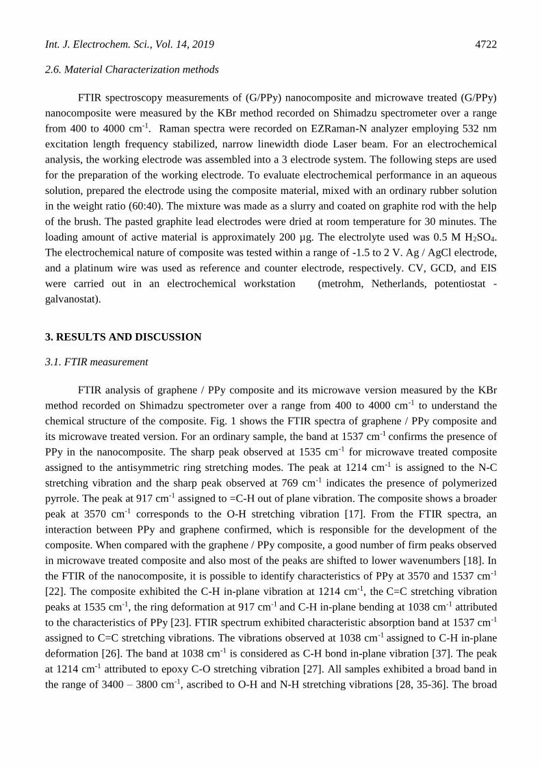
FTIR analysis of graphene / PPy composite and its microwave version measured by the KBr
method recorded on Shimadzu spectrometer over a range from 400 to 4000 cm-1 to understand the
chemical structure of the composite. Fig. 1 shows the FTIR spectra of graphene / PPy composite and
its microwave treated version. For an ordinary sample, the band at 1537 cm-1 confirms the presence of
PPy in the nanocomposite. The sharp peak observed at 1535 cm-1 for microwave treated composite
assigned to the antisymmetric ring stretching modes. The peak at 1214 cm-1 is assigned to the N-C
stretching vibration and the sharp peak observed at 769 cm-1 indicates the presence of polymerized
pyrrole. The peak at 917 cm-1 assigned to =C-H out of plane vibration. The composite shows a broader
peak at 3570 cm-1 corresponds to the O-H stretching vibration [17]. From the FTIR spectra, an
interaction between PPy and graphene confirmed, which is responsible for the development of the
composite. When compared with the graphene / PPy composite, a good number of firm peaks observed
in microwave treated composite and also most of the peaks are shifted to lower wavenumbers [18]. In
the FTIR of the nanocomposite, it is possible to identify characteristics of PPy at 3570 and 1537 cm-1
[22]. The composite exhibited the C-H in-plane vibration at 1214 cm-1, the C=C stretching vibration
peaks at 1535 cm-1, the ring deformation at 917 cm-1 and C-H in-plane bending at 1038 cm-1 attributed
to the characteristics of PPy [23]. FTIR spectrum exhibited characteristic absorption band at 1537 cm-1
assigned to C=C stretching vibrations. The vibrations observed at 1038 cm-1 assigned to C-H in-plane
deformation [26]. The band at 1038 cm-1 is considered as C-H bond in-plane vibration [37]. The peak
at 1214 cm-1 attributed to epoxy C-O stretching vibration [27]. All samples exhibited a broad band in
the range of 3400 – 3800 cm-1, ascribed to O-H and N-H stretching vibrations [28, 35-36]. The broad
Int. J. Electrochem. Sci., Vol. 14, 2019
4723
center peak obtained at 3570 cm-1, of composite attributed to OH vibration and structural OH groups
[32].
Figure 1. FTIR spectra of (a) graphene/polypyrrole composite and (b) microwave treated
graphene/polypyrrole composite
3.2. Raman spectroscopy
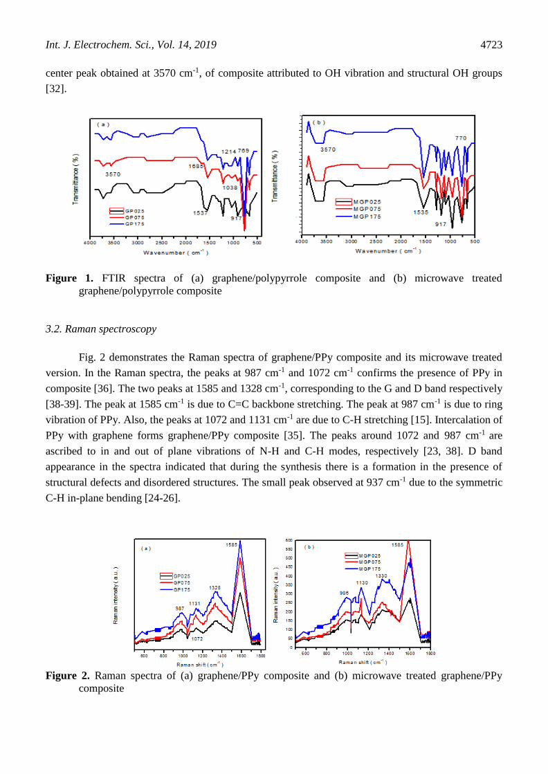
Fig. 2 demonstrates the Raman spectra of graphene/PPy composite and its microwave treated
version. In the Raman spectra, the peaks at 987 cm-1 and 1072 cm-1 confirms the presence of PPy in
composite [36]. The two peaks at 1585 and 1328 cm-1, corresponding to the G and D band respectively
[38-39]. The peak at 1585 cm-1 is due to C=C backbone stretching. The peak at 987 cm-1 is due to ring
vibration of PPy. Also, the peaks at 1072 and 1131 cm-1 are due to C-H stretching [15]. Intercalation of
PPy with graphene forms graphene/PPy composite [35]. The peaks around 1072 and 987 cm-1 are
ascribed to in and out of plane vibrations of N-H and C-H modes, respectively [23, 38]. D band
appearance in the spectra indicated that during the synthesis there is a formation in the presence of
structural defects and disordered structures. The small peak observed at 937 cm-1 due to the symmetric
C-H in-plane bending [24-26].
Figure 2. Raman spectra of (a) graphene/PPy composite and (b) microwave treated graphene/PPy
composite
Int. J. Electrochem. Sci., Vol. 14, 2019
4724
3.3. BET surface area measurement
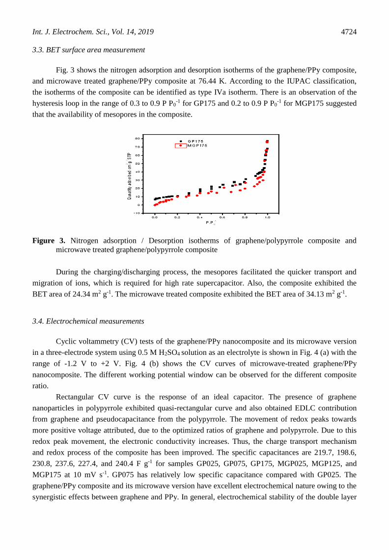
Fig. 3 shows the nitrogen adsorption and desorption isotherms of the graphene/PPy composite,
and microwave treated graphene/PPy composite at 76.44 K. According to the IUPAC classification,
the isotherms of the composite can be identified as type IVa isotherm. There is an observation of the
hysteresis loop in the range of 0.3 to 0.9 P P0-1 for GP175 and 0.2 to 0.9 P P0
-1 for MGP175 suggested
that the availability of mesopores in the composite.
Figure 3. Nitrogen adsorption / Desorption isotherms of graphene/polypyrrole composite and
microwave treated graphene/polypyrrole composite
During the charging/discharging process, the mesopores facilitated the quicker transport and
migration of ions, which is required for high rate supercapacitor. Also, the composite exhibited the
BET area of 24.34 m2 g-1. The microwave treated composite exhibited the BET area of 34.13 m2 g-1.
3.4. Electrochemical measurements
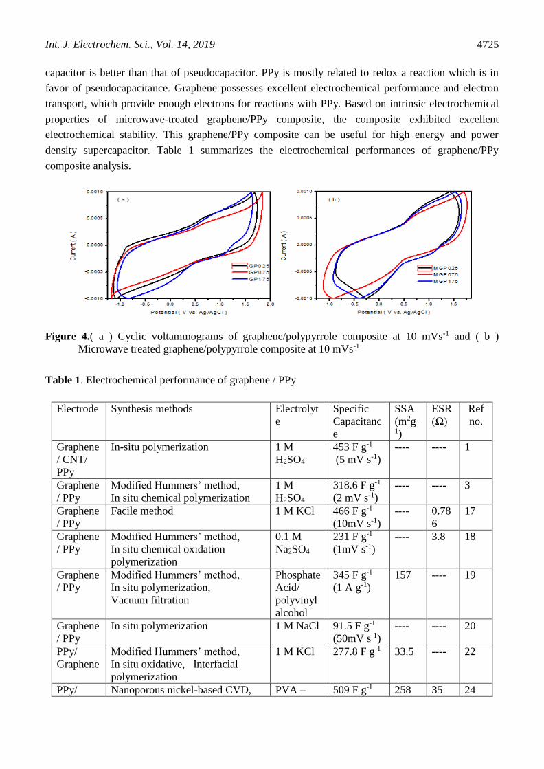
Cyclic voltammetry (CV) tests of the graphene/PPy nanocomposite and its microwave version
in a three-electrode system using 0.5 M H2SO4 solution as an electrolyte is shown in Fig. 4 (a) with the
range of -1.2 V to +2 V. Fig. 4 (b) shows the CV curves of microwave-treated graphene/PPy
nanocomposite. The different working potential window can be observed for the different composite
ratio.
Rectangular CV curve is the response of an ideal capacitor. The presence of graphene
nanoparticles in polypyrrole exhibited quasi-rectangular curve and also obtained EDLC contribution
from graphene and pseudocapacitance from the polypyrrole. The movement of redox peaks towards
more positive voltage attributed, due to the optimized ratios of graphene and polypyrrole. Due to this
redox peak movement, the electronic conductivity increases. Thus, the charge transport mechanism
and redox process of the composite has been improved. The specific capacitances are 219.7, 198.6,
230.8, 237.6, 227.4, and 240.4 F g-1 for samples GP025, GP075, GP175, MGP025, MGP125, and
MGP175 at 10 mV s-1. GP075 has relatively low specific capacitance compared with GP025. The
graphene/PPy composite and its microwave version have excellent electrochemical nature owing to the
synergistic effects between graphene and PPy. In general, electrochemical stability of the double layer
Int. J. Electrochem. Sci., Vol. 14, 2019
4725
capacitor is better than that of pseudocapacitor. PPy is mostly related to redox a reaction which is in
favor of pseudocapacitance. Graphene possesses excellent electrochemical performance and electron
transport, which provide enough electrons for reactions with PPy. Based on intrinsic electrochemical
properties of microwave-treated graphene/PPy composite, the composite exhibited excellent
electrochemical stability. This graphene/PPy composite can be useful for high energy and power
density supercapacitor. Table 1 summarizes the electrochemical performances of graphene/PPy
composite analysis.
Figure 4.( a ) Cyclic voltammograms of graphene/polypyrrole composite at 10 mVs-1 and ( b )
Microwave treated graphene/polypyrrole composite at 10 mVs-1
Table 1. Electrochemical performance of graphene / PPy
Electrode Synthesis methods Electrolyt
e
Specific
Capacitanc
e
SSA
(m2g-
1)
ESR
(Ω)
Ref
no.
Graphene
/ CNT/
PPy
In-situ polymerization 1 M
H2SO4
453 F g-1
(5 mV s-1)
---- ---- 1
Graphene
/ PPy
Modified Hummers’ method,
In situ chemical polymerization
1 M
H2SO4
318.6 F g-1
(2 mV s-1)
---- ---- 3
Graphene
/ PPy
Facile method 1 M KCl 466 F g-1
(10mV s-1)
---- 0.78
6
17
Graphene
/ PPy
Modified Hummers’ method,
In situ chemical oxidation
polymerization
0.1 M
Na2SO4
231 F g-1
(1mV s-1)
---- 3.8 18
Graphene
/ PPy
Modified Hummers’ method,
In situ polymerization,
Vacuum filtration
Phosphate
Acid/
polyvinyl
alcohol
345 F g-1
(1 A g-1)
157 ---- 19
Graphene
/ PPy
In situ polymerization
1 M NaCl 91.5 F g-1
(50mV s-1)
---- ---- 20
PPy/
Graphene
Modified Hummers’ method,
In situ oxidative, Interfacial
polymerization
1 M KCl 277.8 F g-1 33.5 ---- 22
PPy/ Nanoporous nickel-based CVD, PVA – 509 F g-1 258 35 24
Int. J. Electrochem. Sci., Vol. 14, 2019
4726
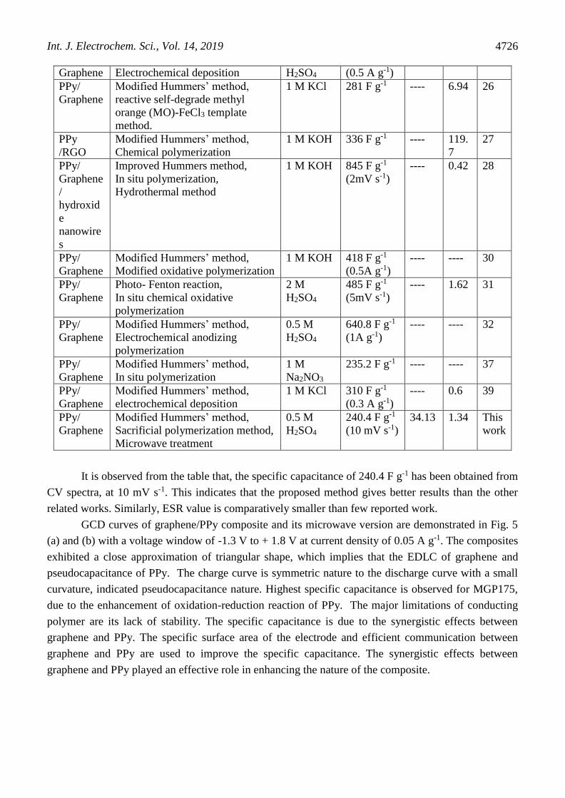
Graphene Electrochemical deposition H2SO4 (0.5 A g-1)
PPy/
Graphene
Modified Hummers’ method,
reactive self-degrade methyl
orange (MO)-FeCl3 template
method.
1 M KCl 281 F g-1 ---- 6.94 26
PPy
/RGO
Modified Hummers’ method,
Chemical polymerization
1 M KOH 336 F g-1 ---- 119.
7
27
PPy/
Graphene
/
hydroxid
e
nanowire
s
Improved Hummers method,
In situ polymerization,
Hydrothermal method
1 M KOH 845 F g-1
(2mV s-1)
---- 0.42 28
PPy/
Graphene
Modified Hummers’ method,
Modified oxidative polymerization
1 M KOH 418 F g-1
(0.5A g-1)
---- ---- 30
PPy/
Graphene
Photo- Fenton reaction,
In situ chemical oxidative
polymerization
2 M
H2SO4
485 F g-1
(5mV s-1)
---- 1.62 31
PPy/
Graphene
Modified Hummers’ method,
Electrochemical anodizing
polymerization
0.5 M
H2SO4
640.8 F g-1
(1A g-1)
---- ---- 32
PPy/
Graphene
Modified Hummers’ method,
In situ polymerization
1 M
Na2NO3
235.2 F g-1 ---- ---- 37
PPy/
Graphene
Modified Hummers’ method,
electrochemical deposition
1 M KCl 310 F g-1
(0.3 A g-1)
---- 0.6 39
PPy/
Graphene
Modified Hummers’ method,
Sacrificial polymerization method,
Microwave treatment
0.5 M
H2SO4
240.4 F g-1
(10 mV s-1)
34.13 1.34 This
work
It is observed from the table that, the specific capacitance of 240.4 F g-1 has been obtained from
CV spectra, at 10 mV s-1. This indicates that the proposed method gives better results than the other
related works. Similarly, ESR value is comparatively smaller than few reported work.
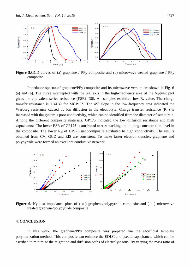
GCD curves of graphene/PPy composite and its microwave version are demonstrated in Fig. 5
(a) and (b) with a voltage window of -1.3 V to + 1.8 V at current density of 0.05 A g-1. The composites
exhibited a close approximation of triangular shape, which implies that the EDLC of graphene and
pseudocapacitance of PPy. The charge curve is symmetric nature to the discharge curve with a small
curvature, indicated pseudocapacitance nature. Highest specific capacitance is observed for MGP175,
due to the enhancement of oxidation-reduction reaction of PPy. The major limitations of conducting
polymer are its lack of stability. The specific capacitance is due to the synergistic effects between
graphene and PPy. The specific surface area of the electrode and efficient communication between
graphene and PPy are used to improve the specific capacitance. The synergistic effects between
graphene and PPy played an effective role in enhancing the nature of the composite.
Int. J. Electrochem. Sci., Vol. 14, 2019
4727
Figure 5.GCD curves of (a) graphene / PPy composite and (b) microwave treated graphene / PPy
composite
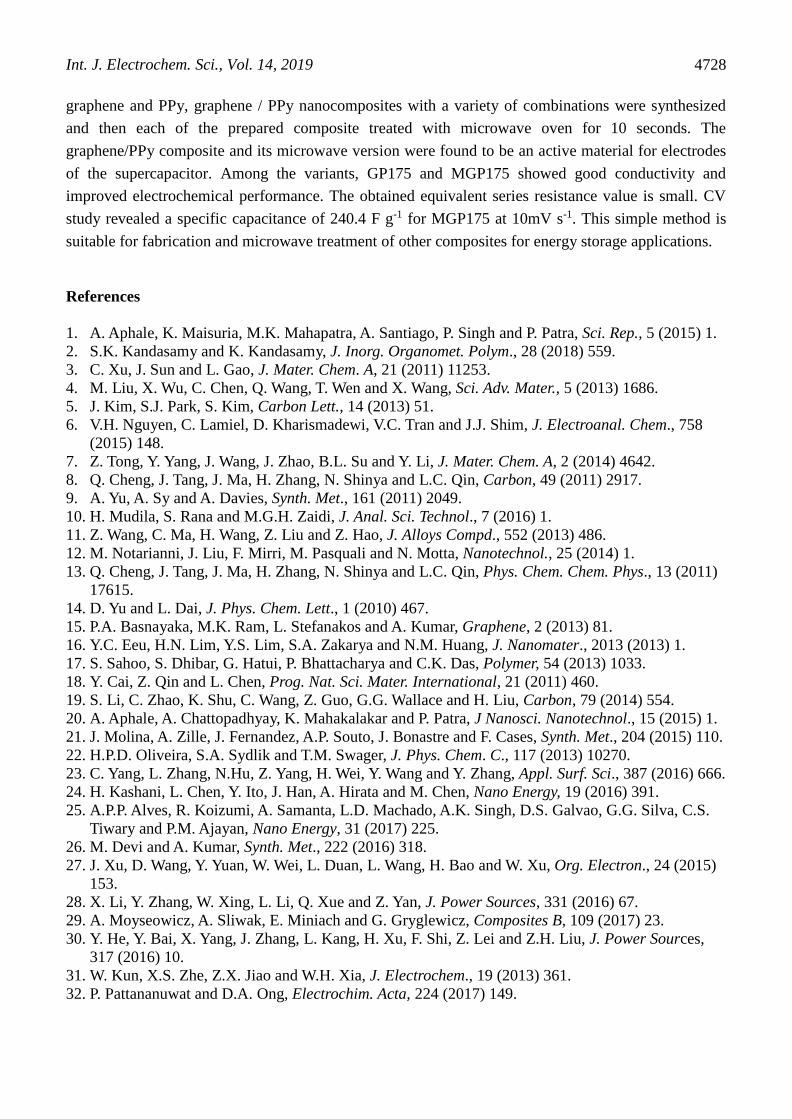
Impedance spectra of graphene/PPy composite and its microwave version are shown in Fig. 6
(a) and (b). The curve intercepted with the real axis in the high-frequency area of the Nyquist plot
gives the equivalent series resistance (ESR) [36]. All samples exhibited low Rs value. The charge
transfer resistance is 1.34 Ω for MGP175. The 45o slope in the low-frequency area indicated the
Warburg resistance caused by ion diffusion in the electrolyte. Charge transfer resistance (Rct) is
increased with the system’s poor conductivity, which can be identified from the diameter of semicircle.
Among the different composite materials, GP175 indicated the low diffusion resistance and high
capacitance. The lower ESR of GP175 is attributed to π-π stacking and doping concentration level in
the composite. The lower Rct of GP175 nanocomposite attributed to high conductivity. The results
obtained from CV, GCD and EIS are consistent. To make faster electron transfer, graphene and
polypyrrole were formed an excellent conductive network.
Figure 6. Nyquist impedance plots of ( a ) graphene/polypyrrole composite and ( b ) microwave
treated graphene/polypyrrole composite
4. CONCLUSION
In this work, the graphene/PPy composite was prepared via the sacrificial template
polymerization method. This composite can enhance the EDLC and pseudocapacitance, which can be
ascribed to minimize the migration and diffusion paths of electrolyte ions. By varying the mass ratio of
Int. J. Electrochem. Sci., Vol. 14, 2019
4728
graphene and PPy, graphene / PPy nanocomposites with a variety of combinations were synthesized
and then each of the prepared composite treated with microwave oven for 10 seconds. The
graphene/PPy composite and its microwave version were found to be an active material for electrodes
of the supercapacitor. Among the variants, GP175 and MGP175 showed good conductivity and
improved electrochemical performance. The obtained equivalent series resistance value is small. CV
study revealed a specific capacitance of 240.4 F g-1 for MGP175 at 10mV s-1. This simple method is
suitable for fabrication and microwave treatment of other composites for energy storage applications.
References
1. A. Aphale, K. Maisuria, M.K. Mahapatra, A. Santiago, P. Singh and P. Patra, Sci. Rep., 5 (2015) 1.
2. S.K. Kandasamy and K. Kandasamy, J. Inorg. Organomet. Polym., 28 (2018) 559.
3. C. Xu, J. Sun and L. Gao, J. Mater. Chem. A, 21 (2011) 11253.
4. M. Liu, X. Wu, C. Chen, Q. Wang, T. Wen and X. Wang, Sci. Adv. Mater., 5 (2013) 1686.
5. J. Kim, S.J. Park, S. Kim, Carbon Lett., 14 (2013) 51.
6. V.H. Nguyen, C. Lamiel, D. Kharismadewi, V.C. Tran and J.J. Shim, J. Electroanal. Chem., 758
(2015) 148.
7. Z. Tong, Y. Yang, J. Wang, J. Zhao, B.L. Su and Y. Li, J. Mater. Chem. A, 2 (2014) 4642.
8. Q. Cheng, J. Tang, J. Ma, H. Zhang, N. Shinya and L.C. Qin, Carbon, 49 (2011) 2917.
9. A. Yu, A. Sy and A. Davies, Synth. Met., 161 (2011) 2049.
10. H. Mudila, S. Rana and M.G.H. Zaidi, J. Anal. Sci. Technol., 7 (2016) 1.
11. Z. Wang, C. Ma, H. Wang, Z. Liu and Z. Hao, J. Alloys Compd., 552 (2013) 486.
12. M. Notarianni, J. Liu, F. Mirri, M. Pasquali and N. Motta, Nanotechnol., 25 (2014) 1.
13. Q. Cheng, J. Tang, J. Ma, H. Zhang, N. Shinya and L.C. Qin, Phys. Chem. Chem. Phys., 13 (2011)
17615.
14. D. Yu and L. Dai, J. Phys. Chem. Lett., 1 (2010) 467.
15. P.A. Basnayaka, M.K. Ram, L. Stefanakos and A. Kumar, Graphene, 2 (2013) 81.
16. Y.C. Eeu, H.N. Lim, Y.S. Lim, S.A. Zakarya and N.M. Huang, J. Nanomater., 2013 (2013) 1.
17. S. Sahoo, S. Dhibar, G. Hatui, P. Bhattacharya and C.K. Das, Polymer, 54 (2013) 1033.
18. Y. Cai, Z. Qin and L. Chen, Prog. Nat. Sci. Mater. International, 21 (2011) 460.
19. S. Li, C. Zhao, K. Shu, C. Wang, Z. Guo, G.G. Wallace and H. Liu, Carbon, 79 (2014) 554.
20. A. Aphale, A. Chattopadhyay, K. Mahakalakar and P. Patra, J Nanosci. Nanotechnol., 15 (2015) 1.
21. J. Molina, A. Zille, J. Fernandez, A.P. Souto, J. Bonastre and F. Cases, Synth. Met., 204 (2015) 110.
22. H.P.D. Oliveira, S.A. Sydlik and T.M. Swager, J. Phys. Chem. C., 117 (2013) 10270.
23. C. Yang, L. Zhang, N.Hu, Z. Yang, H. Wei, Y. Wang and Y. Zhang, Appl. Surf. Sci., 387 (2016) 666.
24. H. Kashani, L. Chen, Y. Ito, J. Han, A. Hirata and M. Chen, Nano Energy, 19 (2016) 391.
25. A.P.P. Alves, R. Koizumi, A. Samanta, L.D. Machado, A.K. Singh, D.S. Galvao, G.G. Silva, C.S.
Tiwary and P.M. Ajayan, Nano Energy, 31 (2017) 225.
26. M. Devi and A. Kumar, Synth. Met., 222 (2016) 318.
27. J. Xu, D. Wang, Y. Yuan, W. Wei, L. Duan, L. Wang, H. Bao and W. Xu, Org. Electron., 24 (2015)
153.
28. X. Li, Y. Zhang, W. Xing, L. Li, Q. Xue and Z. Yan, J. Power Sources, 331 (2016) 67.
29. A. Moyseowicz, A. Sliwak, E. Miniach and G. Gryglewicz, Composites B, 109 (2017) 23.
30. Y. He, Y. Bai, X. Yang, J. Zhang, L. Kang, H. Xu, F. Shi, Z. Lei and Z.H. Liu, J. Power Sources,
317 (2016) 10.
31. W. Kun, X.S. Zhe, Z.X. Jiao and W.H. Xia, J. Electrochem., 19 (2013) 361.
32. P. Pattananuwat and D.A. Ong, Electrochim. Acta, 224 (2017) 149.
Int. J. Electrochem. Sci., Vol. 14, 2019
4729
33. W.K. Chee, H.N. Lim, I. Harrison, K.F. Chong, Z. Zainal, C.H. Ng and N.M. Huang, Electrochim.
Acta, 157 (2015) 88.
34. X. Lu, F. Zhang, H. Dou, C. Yuan, S. Yang, L. Hao, L. Shen, L. Zhang and X. Zhang, Electrochim.
Acta, 69 (2012) 160.
35. Y. Liu, H. Wang, J. Zhou, L. Bian, E. Zhu, J. Hai, J. Tang and W. Tang, Electrochim. Acta, 112
(2013) 44.
36. C. Bora, J. Sharma and S. Dolui, J. Phys. Chem. C, 118 (2014) 29688.
37. L. Ma, R. Liu, H. Niu, M. Zhao and Y. Huang, Composites Sci. Technol., 137 (2016) 87.
38. S. Lyu, H. Chang, F. Fu, L. Hu, J. Huang and S. Wang, J. Power Sources, 327 (2016) 438.
39. X. Zuo, Y. Zhang, L. Si, B. Zhou, B. Zhao, L. Zhu and X. Jiang, J. Alloys Compd., 688 (2016) 140.
© 2019 The Authors. Published by ESG (www.electrochemsci.org). This article is an open access
article distributed under the terms and conditions of the Creative Commons Attribution license
(http://creativecommons.org/licenses/by/4.0/).


![Synthesis and Electrochemical Performance of Polypyrrole ...carbonlett.org/Upload/files/CARBONLETT/[157-160]-04.pdf · Synthesis and Electrochemical Performance of Polypyrrole-](https://img.pdfslide.us/doc/110x75/5b7197897f8b9a6f6b8ba2b2/synthesis-and-electrochemical-performance-of-polypyrrole-157-160-04pdf.jpg)