Embed Size (px)
Citation preview
Structural Analysis of Post-Tensioned Concrete Containment Building Repair using 3-d Finite Elements
Authors: Peter R. Barrett, P.E., Computer Aided Engineering Associates Inc., 60 Middle Quarter Mall, Woodbury, CT 06798, (203) 263-4606, [email protected] Daniel B Fisher Jr. P.E., AREVA Group, 7207 IBM Drive, Charlotte, N.C. 28262 ABSTRACT The most efficient method of replacement of major internal components such as steam generators in nuclear power plants may require the creation of a construction opening in the side of the containment building. For repairing post-tensioned concrete containment buildings, a major design challenge is to develop the most efficient scheme for tendon de-tensioning and subsequent re-tensioning. Stresses and displacements must be monitored in the containment wall and liner throughout the repair sequence. Nonlinear finite element analysis using the ANSYS general analysis package can be used to simulate the entire construction process and thus assure an adequate design margin of safety at all stages. Recent developments in computer CPU speed and RAM advancements have made it possible to perform complex nonlinear Finite Element Analysis (FEA) on an entire containment building overnight on a desktop machine. The nonlinear analysis technique discussed in this paper includes explicit modeling of the tendons and concrete including the tendon-concrete load interaction. Tendon tensioning and de-tensioning is modeled using an initial strain approach where link elements are coupled to the containment building wall. The wall is modeled with 3-D brick elements. Element birth and death is used to simulate the process of cutting the construction opening and subsequent patching of the wall in a stress-free state. This modeling method is critical to capture the local bending response in the patch that is often neglected in simplified models. This paper presents the details while illustrating the importance of explicitly modeling the construction and hole-patch-wall interaction. INTRODUCTION
Replacing steam generators requires material and personnel access to the interior of the reactor building. Development of the temporary construction access must show that:
1. There will be no damage to the containment building at any time during the
construction work on an opening.
2. Creating an opening in the wall of the containment building and patching the concrete does not change the structural integrity of the building. Structural analysis of the post-tensioned concrete containment building repair using the finite element method provides an accurate and efficient means of evaluating these criteria. The analysis input to meet these requirements includes:
• Modeling a symmetric portion of the building (typically 180 degrees or less) • Modeling the hoop and vertical tendons explicitly. • If necessary modeling the equipment hatch area and evaluating its contribution to the
buildings overall state of stress. • Developing a geometrically parametric model of the construction opening so that it
can be adjusted to variable sizes to meet design criteria. • Developing the ability to remove individual tendons (hoop or vertical). • Developing the ability to vary an individual tendon’s force (hoop or vertical) • Including the effects of tendon loss for both vertical and horizontal tendons.
Each of these capabilities is illustrated in the body of this paper through the example analysis of a representative containment building. The results presented are typical of what might occur in an actual evaluation, but are not specific to any real structure.
FINITE ELEMENT MODEL DEVELOPMENT
In constructing a finite element model there is always the trade off between computational accuracy and computational time to solve. As computers get faster, we are able to build models that provide a better understanding of the physical response the building under goes during the repair operations. The independent modeling of the concrete, tendons, and patch interface will result in more accurate design evaluations. The following element types and there applications are explained in more detail:
1. 3-d brick elements to model the concrete building 2. 1-d truss elements to model the tendons 3. Spring elements to connect the patch to the building 4. Surface-to-surface contact elements to simulate the repair boundary
between the patch and existing wall
Containment Wall - 3-d Brick Elements Brick elements are used to model the containment wall since they can predict a nonlinear through thickness stress distribution that cannot be captured using conventional shell modeling. The brick elements will also predict the incompatibility of the stress free patch and the pre-loaded building nonlinear deformation pattern. A large through-thickness bending stress distribution is most prevalent at the patch after tendon re-tensioning. Mesh density studies show that six elements through the thickness are adequate to capture this response and still preserve a model that can be easily solved on a desktop computer. The liner plate is conservatively ignored in the demonstration model, although it could easily be added in the form of shell elements on the inside face of the
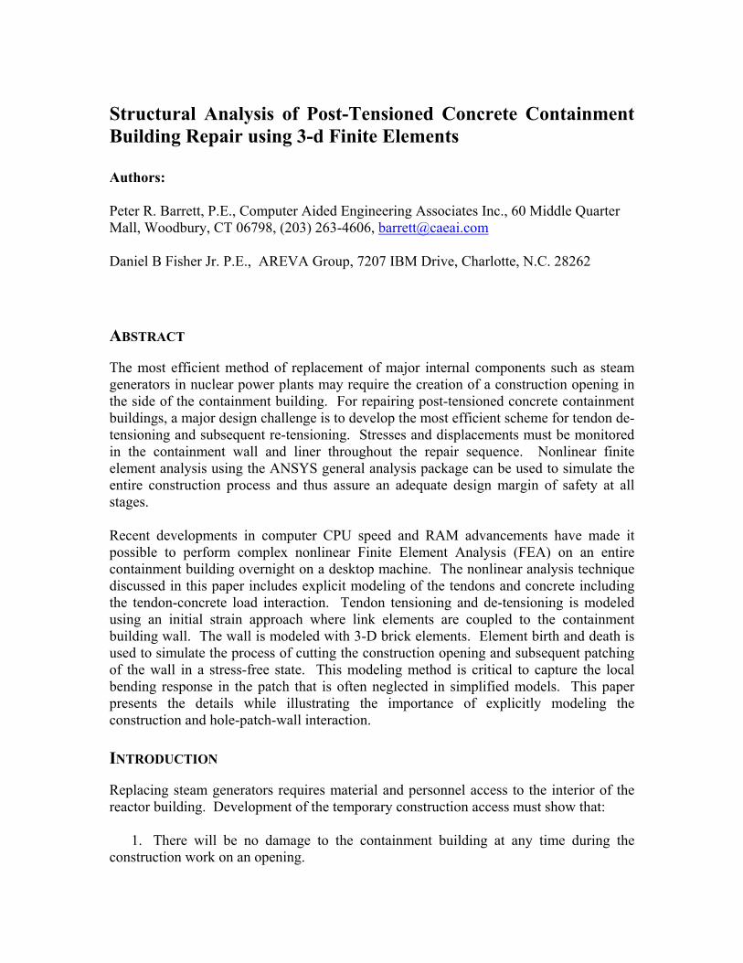
containment building. Brick elements are aligned with the tendons such that the tendon (truss) elements line-up with the containment (brick) concrete elements. These coincident nodes allow for direct coupling between the concrete and tendon elements. Figure 1 illustrates a 180-degree model. The patch region is illustrated in a different color since the material properties will change after the hole is replaced with the patch. The size and shape of the patch is defined as user-friendly parametric input in the analysis file to automate the process of performing design iterations. The abutments are also explicitly modeled with bricks to capture their eccentric stiffness and provide tendon attachment points.
FIGURE 1 - FINITE ELEMENT MODEL OF CONTAINMENT BUILDING
1-d Truss Tendon Elements Truss elements are used to model the vertical and hoop tendons to provide flexibility in evaluating variations in tendon loads (de-tensioning and re-tensioning) during the repair design process. Truss element nodes are defined at coincident locations of the brick elements where load transfer is required between tendons and the containment wall. Rigid beam elements are used at the abutments (connecting the ends of the tendons to the containment wall) to distribute the tendon support loads to the concrete elements since the anchorages are not modeled explicitly. Coupling in the radial direction between the tendon elements and the containment wall is used to transfer load between the hoop tendons and the containment wall. Other degrees of freedom of the tendons not required are fixed to prevent rigid body motion. An initial strain is used to define the tendon forces. Forces are derived directly from the stresses and tendon areas. Each element is given a different initial strain that is a function of the tendon loads and losses. Tendon strains (forces) are calculated from a scripted input file such that all tendon loads can be changed with a single variable. The tendon loads are defined using ANSYS APDL scripts that compute the actual tendon load from its geometric position taking into
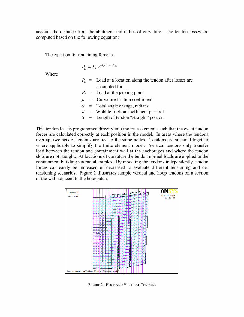
account the distance from the abutment and radius of curvature. The tendon losses are computed based on the following equation:
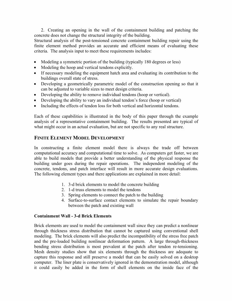
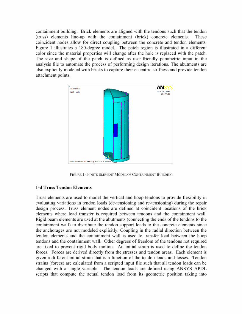
This tendon loss is programmed directly into the truss elements such that the exact tendon forces are calculated correctly at each position in the model. In areas where the tendons overlap, two sets of tendons are tied to the same nodes. Tendons are smeared together where applicable to simplify the finite element model. Vertical tendons only transfer load between the tendon and containment wall at the anchorages and where the tendon slots are not straight. At locations of curvature the tendon normal loads are applied to the containment building via radial couples. By modeling the tendons independently, tendon forces can easily be increased or decreased to evaluate different tensioning and de-tensioning scenarios. Figure 2 illustrates sample vertical and hoop tendons on a section of the wall adjacent to the hole/patch.
FIGURE 2 - HOOP AND VERTICAL TENDONS
The equation for remaining force is: ( )SK
JL ePP +−= αµ Where LP = Load at a location along the tendon after losses are accounted for JP = Load at the jacking point µ = Curvature friction coefficient α = Total angle change, radians K = Wobble friction coefficient per foot S = Length of tendon “straight” portion
1-d Spring Elements In the boundaries around the patch, spring elements are used to form a continuous bond between the containment wall and future patch region, prior to the patch being cut. The use of independent nodes for the patch wall along the cut line allows for the subsequent modeling of the opening and patching loading sequence. The spring elements are defined with large spring stiffnesses during the initial analysis steps where the building is modeled prior to the opening being cut and subsequent de-tensioning. After the hole is cut, the springs are kept at a large stiffness to restrict rigid body motion of the “killed” elements in the hole. Upon patching and engaging of the contact elements, the spring elements are reduced to a very low stiffness to allow any relative motion to occur between the patch and wall that is not constrained by the contact elements. Surface-to-Surface Contact Elements Surface-to-surface contact elements are used to simulate the repaired boundary between the patch and existing wall such that a loss of bond can be simulated. The contact elements are killed during the initial stages of the analysis where the previously described springs hold the original wall in-place. Contact elements are activated after the patch is “birthed” to transmit compressive and shear loads (based on a defined friction coefficient), and yet not allow tensile forces to develop between the patch and surrounding concrete wall. Friction is used to simulate the effects of the concrete to resist shear loads at the edges of the patch. LOADING SEQUENCE
Since the analysis of the construction sequence is nonlinear and path dependent, it is necessary for the analysis to follow the construction sequence. Each load step is scripted to define changes where applicable in tendon loads, material properties, gravity loads, and patch interface elements. A sample loading sequence is summarized as follows:
! LS 1: Dead Load + Tendon Loads + Equipment Loading ! LS 2: Dead + Tendons + Equipment + Accident ! LS 3: Dead + Tendons + Equipment ! LS 4: Tendons de-tensioned in hole only - vertical and horizontal ! LS 5: Tendons de-tensioned locally away from the hole ! LS 6: Create the hole in the wall ! LS 7: Remaining vertical tendons detensioned as necessary ! LS 8: Patch installed stress free ! LS 9: Patch installed and contact elements activated ! LS 10: Springs removed ! LS 11: Partially re-tension verticals tendons ! LS 12: Partially re-tension hoop tendons ! LS 13: Fully re-tension hoop and vertical tendons ! LS 14: Fully re-tensioned hoop and vertical tendons + Accident
The loading sequence defined above was automated using scripts in ANSYS. For each load step, stress, force and displacement data can be extracted from the finite element model and processed to determine the adequacy of the building to support the defined loading. The analyses are nonlinear since element birth and death is used to create the hole and replace the concrete in a stress free state. The contact elements also require an iterative solution. By developing a user-friendly automated sequence, the analysis model can be used as a design tool to determine the most efficient size of opening and pattern of tendon de-tensioning and subsequent re-tensioning. The input script can be run by a designer without the need of being an analysis expert. ANALYSIS RESULTS
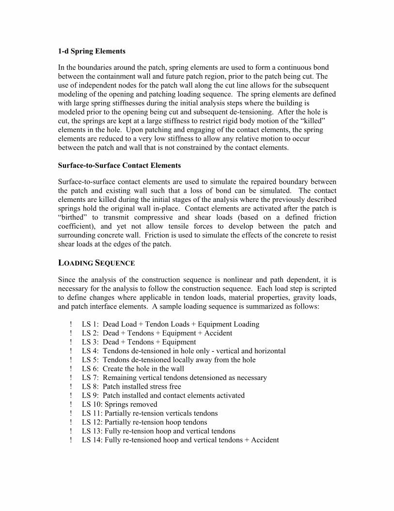
Since the analysis of the construction sequence is nonlinear and path dependent, it is necessary for the analysis to follow the construction sequence explicitly. Sequential loading allows for post-processing the analysis results in form of history plots that track the concrete forces and displacements. Results from selective load steps are provided to demonstrate the effects of explicitily modeling the repair on the nominal building stresses. Figure 3 illustrates the hoop and vertical stresses under tendon and dead loads prior to the repair. By modeling the abutments explicitly, the stress concentrations are captured in this area. For all the contour plots illustrated in this report, the blue regions represent compression, while the red areas represent tensile stresses. For all the containment building figures, the same contour scales are used so the colors are consistent between plots.
FIGURE 3 HOOP AND VERTICAL STRESS UNDER TENDON AND DEAD LOADS
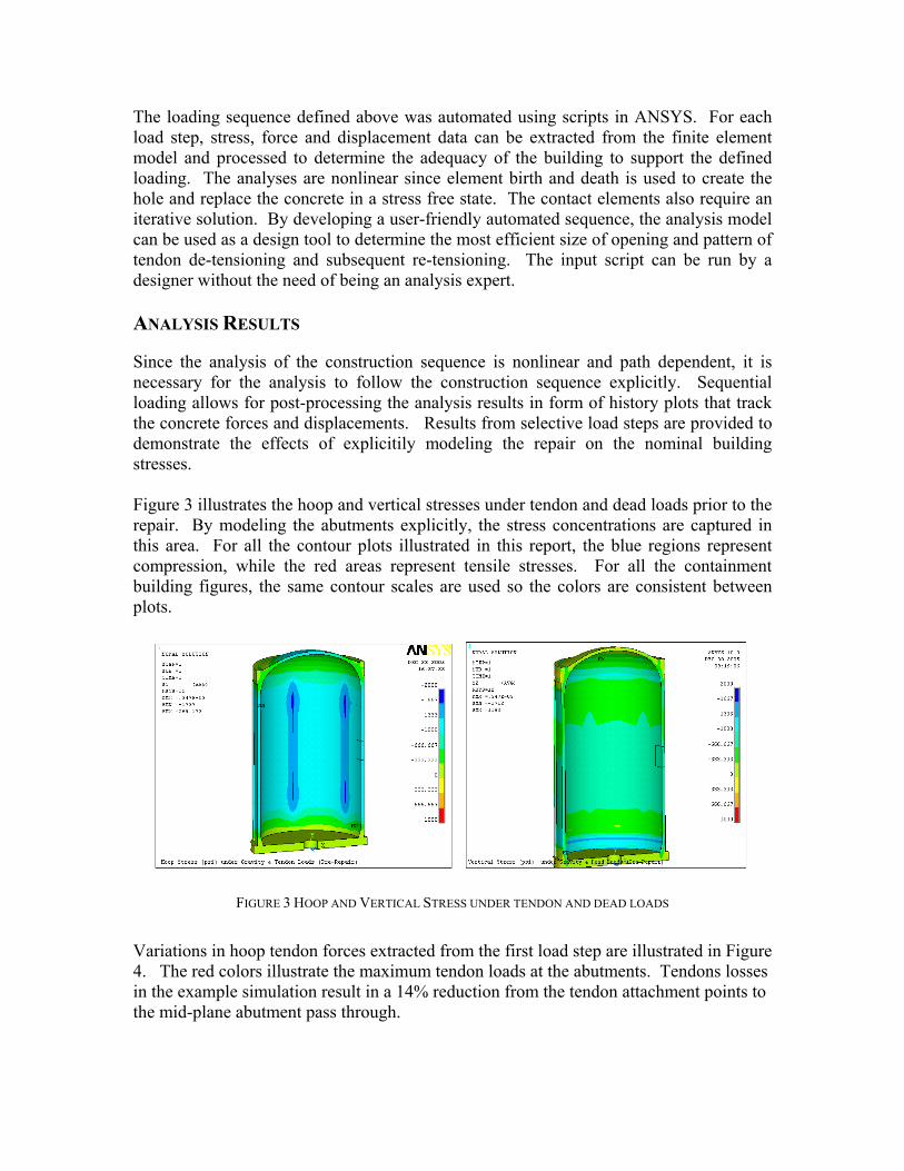
Variations in hoop tendon forces extracted from the first load step are illustrated in Figure 4. The red colors illustrate the maximum tendon loads at the abutments. Tendons losses in the example simulation result in a 14% reduction from the tendon attachment points to the mid-plane abutment pass through.
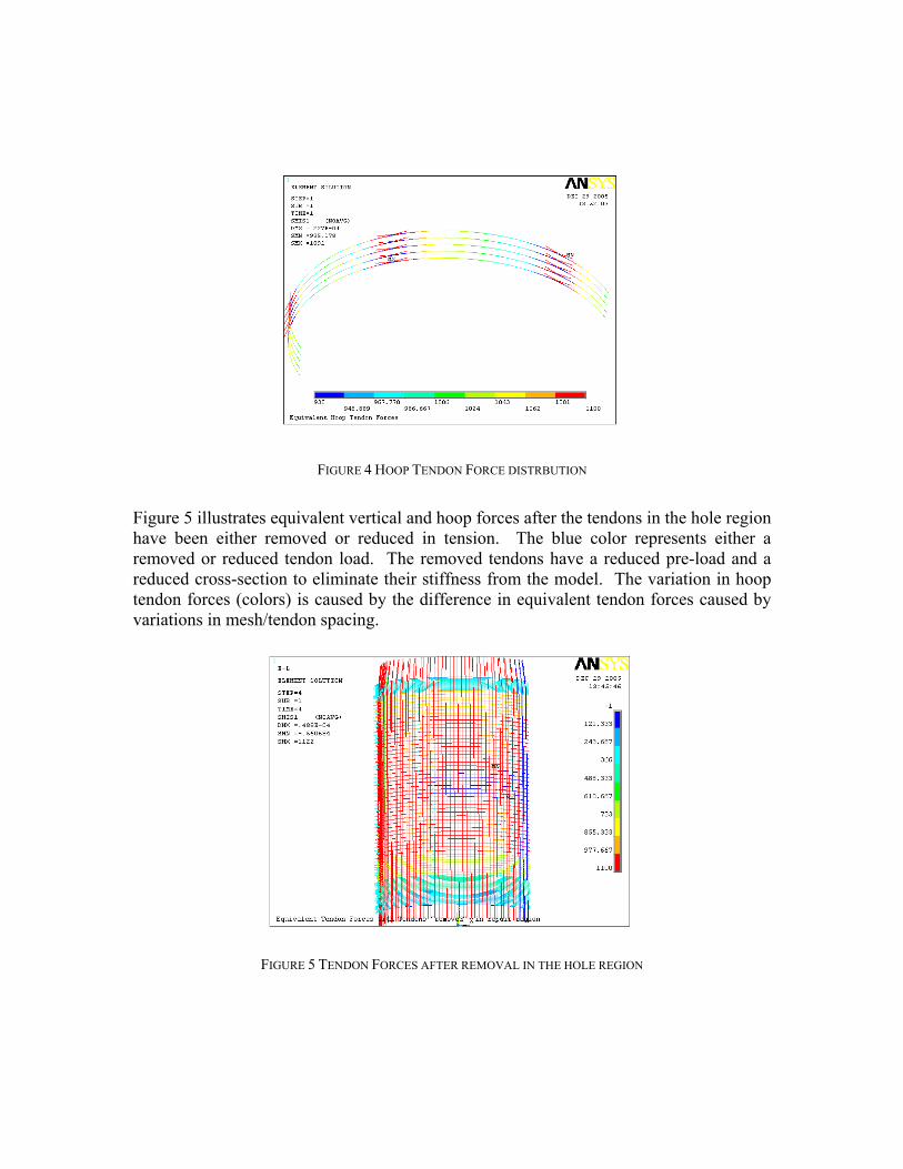
FIGURE 4 HOOP TENDON FORCE DISTRBUTION
Figure 5 illustrates equivalent vertical and hoop forces after the tendons in the hole region have been either removed or reduced in tension. The blue color represents either a removed or reduced tendon load. The removed tendons have a reduced pre-load and a reduced cross-section to eliminate their stiffness from the model. The variation in hoop tendon forces (colors) is caused by the difference in equivalent tendon forces caused by variations in mesh/tendon spacing.
FIGURE 5 TENDON FORCES AFTER REMOVAL IN THE HOLE REGION
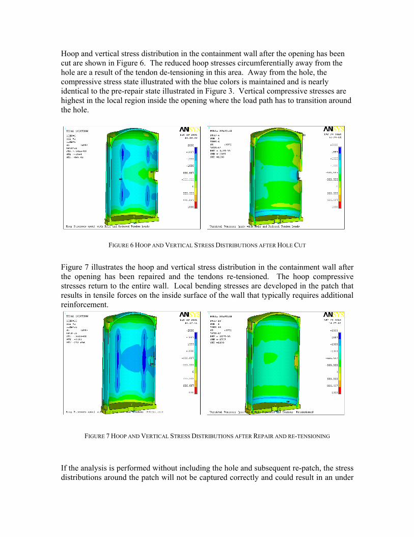
Hoop and vertical stress distribution in the containment wall after the opening has been cut are shown in Figure 6. The reduced hoop stresses circumferentially away from the hole are a result of the tendon de-tensioning in this area. Away from the hole, the compressive stress state illustrated with the blue colors is maintained and is nearly identical to the pre-repair state illustrated in Figure 3. Vertical compressive stresses are highest in the local region inside the opening where the load path has to transition around the hole.
FIGURE 6 HOOP AND VERTICAL STRESS DISTRIBUTIONS AFTER HOLE CUT
Figure 7 illustrates the hoop and vertical stress distribution in the containment wall after the opening has been repaired and the tendons re-tensioned. The hoop compressive stresses return to the entire wall. Local bending stresses are developed in the patch that results in tensile forces on the inside surface of the wall that typically requires additional reinforcement.
FIGURE 7 HOOP AND VERTICAL STRESS DISTRIBUTIONS AFTER REPAIR AND RE-TENSIONING
If the analysis is performed without including the hole and subsequent re-patch, the stress distributions around the patch will not be captured correctly and could result in an under
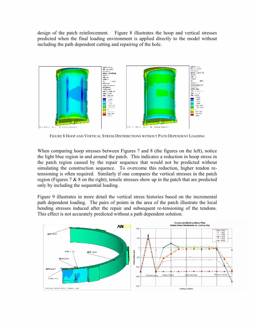
design of the patch reinforcement. Figure 8 illustrates the hoop and vertical stresses predicted when the final loading environment is applied directly to the model without including the path dependent cutting and repairing of the hole.
FIGURE 8 HOOP AND VERTICAL STRESS DISTRIBUTIONS WITHOUT PATH DEPENDENT LOADING
When comparing hoop stresses between Figures 7 and 8 (the figures on the left), notice the light blue region in and around the patch. This indicates a reduction in hoop stress in the patch region caused by the repair sequence that would not be predicted without simulating the construction sequence. To overcome this reduction, higher tendon re-tensioning is often required. Similarly if one compares the vertical stresses in the patch region (Figures 7 & 8 on the right), tensile stresses show up in the patch that are predicted only by including the sequential loading. Figure 9 illustrates in more detail the vertical stress histories based on the incremental path dependent loading. The pairs of points in the area of the patch illustrate the local bending stresses induced after the repair and subsequent re-tensioning of the tendons. This effect is not accurately predicted without a path dependent solution.
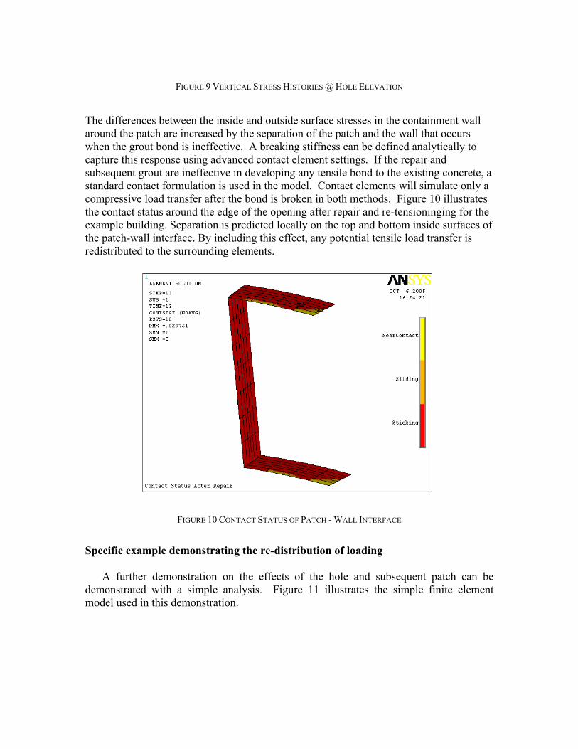
FIGURE 9 VERTICAL STRESS HISTORIES @ HOLE ELEVATION
The differences between the inside and outside surface stresses in the containment wall around the patch are increased by the separation of the patch and the wall that occurs when the grout bond is ineffective. A breaking stiffness can be defined analytically to capture this response using advanced contact element settings. If the repair and subsequent grout are ineffective in developing any tensile bond to the existing concrete, a standard contact formulation is used in the model. Contact elements will simulate only a compressive load transfer after the bond is broken in both methods. Figure 10 illustrates the contact status around the edge of the opening after repair and re-tensioninging for the example building. Separation is predicted locally on the top and bottom inside surfaces of the patch-wall interface. By including this effect, any potential tensile load transfer is redistributed to the surrounding elements.
FIGURE 10 CONTACT STATUS OF PATCH - WALL INTERFACE
Specific example demonstrating the re-distribution of loading
A further demonstration on the effects of the hole and subsequent patch can be demonstrated with a simple analysis. Figure 11 illustrates the simple finite element model used in this demonstration.
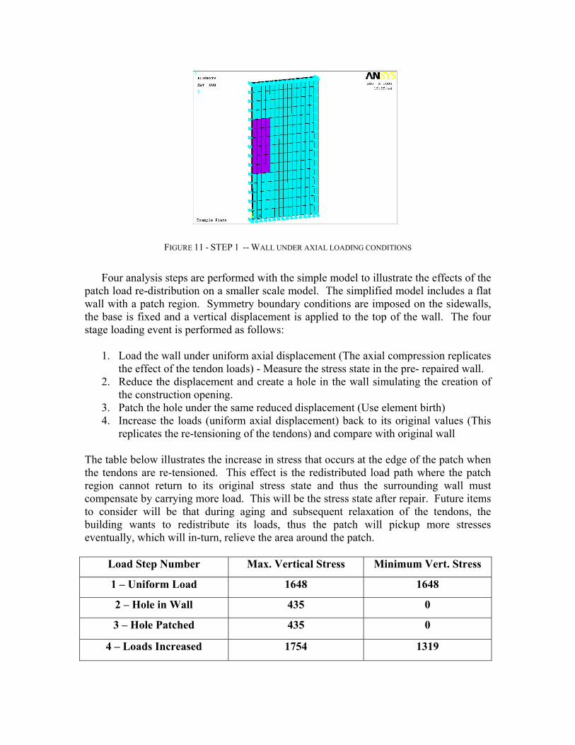
FIGURE 11 - STEP 1 -- WALL UNDER AXIAL LOADING CONDITIONS
Four analysis steps are performed with the simple model to illustrate the effects of the
patch load re-distribution on a smaller scale model. The simplified model includes a flat wall with a patch region. Symmetry boundary conditions are imposed on the sidewalls, the base is fixed and a vertical displacement is applied to the top of the wall. The four stage loading event is performed as follows:
1. Load the wall under uniform axial displacement (The axial compression replicates
the effect of the tendon loads) - Measure the stress state in the pre- repaired wall. 2. Reduce the displacement and create a hole in the wall simulating the creation of
the construction opening. 3. Patch the hole under the same reduced displacement (Use element birth) 4. Increase the loads (uniform axial displacement) back to its original values (This
replicates the re-tensioning of the tendons) and compare with original wall The table below illustrates the increase in stress that occurs at the edge of the patch when the tendons are re-tensioned. This effect is the redistributed load path where the patch region cannot return to its original stress state and thus the surrounding wall must compensate by carrying more load. This will be the stress state after repair. Future items to consider will be that during aging and subsequent relaxation of the tendons, the building wants to redistribute its loads, thus the patch will pickup more stresses eventually, which will in-turn, relieve the area around the patch.
Load Step Number Max. Vertical Stress Minimum Vert. Stress
1 – Uniform Load 1648 1648
2 – Hole in Wall 435 0
3 – Hole Patched 435 0
4 – Loads Increased 1754 1319
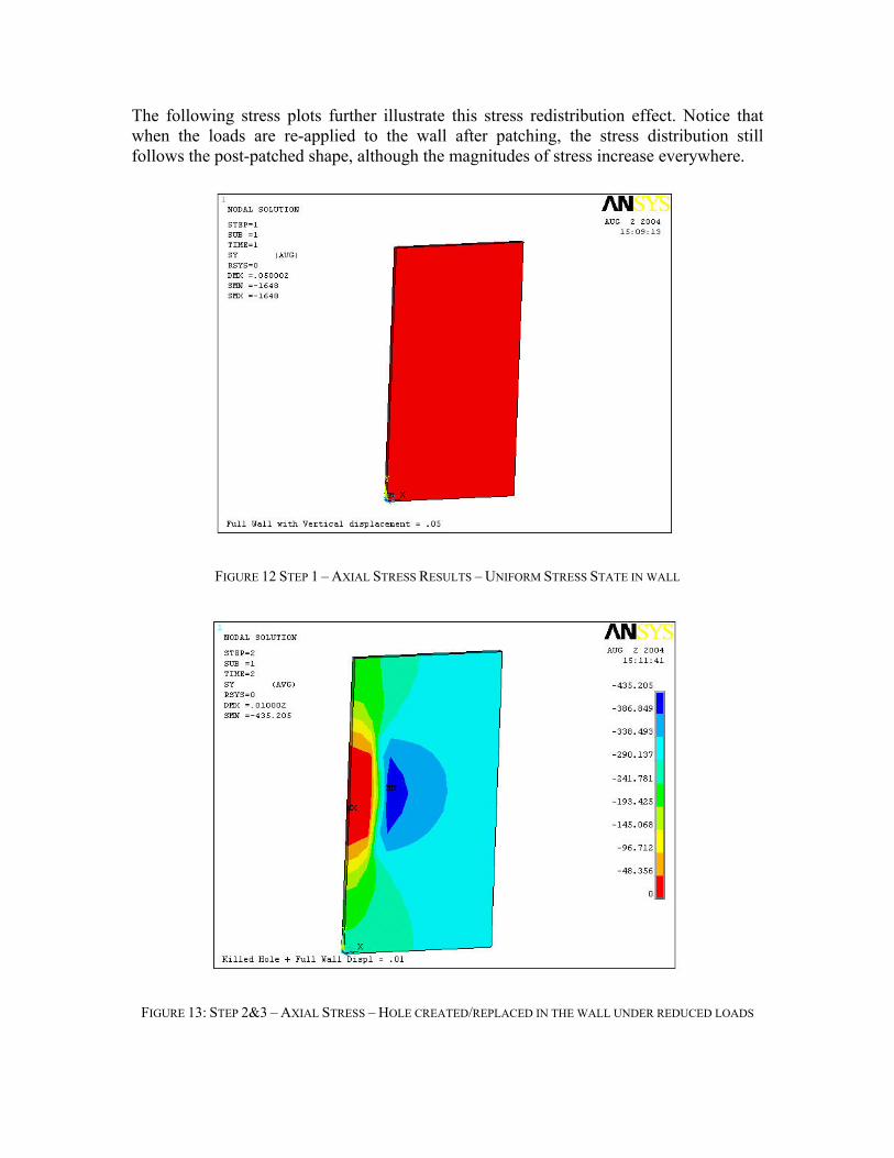
The following stress plots further illustrate this stress redistribution effect. Notice that when the loads are re-applied to the wall after patching, the stress distribution still follows the post-patched shape, although the magnitudes of stress increase everywhere.
FIGURE 12 STEP 1 – AXIAL STRESS RESULTS – UNIFORM STRESS STATE IN WALL
FIGURE 13: STEP 2&3 – AXIAL STRESS – HOLE CREATED/REPLACED IN THE WALL UNDER REDUCED LOADS
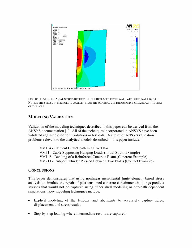
FIGURE 14: STEP 4 – AXIAL STRESS RESULTS – HOLE REPLACED IN THE WALL WITH ORIGINAL LOADS – NOTICE THE STRESS IN THE HOLE IS SMALLER THAN THE ORIGINAL CONDITION AND INCREASED AT THE EDGE OF THE HOLE.
MODELING VALIDATION Validation of the modeling techniques described in this paper can be derived from the ANSYS documentation [1]. All of the techniques incorporated in ANSYS have been validated against closed form solutions or test data. A subset of ANSYS validation problems relevant to the analytical models described in this paper include: VM194 - Element Birth/Death in a Fixed Bar VM31 - Cable Supporting Hanging Loads (Initial Strain Example) VM146 - Bending of a Reinforced Concrete Beam (Concrete Example) VM211 - Rubber Cylinder Pressed Between Two Plates (Contact Example) CONCLUSIONS
This paper demonstrates that using nonlinear incremental finite element based stress analysis to simulate the repair of post-tensioned concrete containment buildings predicts stresses that would not be captured using either shell modeling or non-path dependent simulations. Key modeling techniques include: • Explicit modeling of the tendons and abutments to accurately capture force,
displacement and stress results. • Step-by-step loading where intermediate results are captured.
• Element Birth and Death modeling that captures the true response of creating and repairing construction openings.
• Automated analysis files with user-friendly input parameters such that allow the
designer to perform design iterations without becoming an analysis expert. REFERENCES
[1] ANSYS, Inc., "ANSYS Verification Manual", Release 10.0 Documentation for ANSYS, July 18,
2005.