Embed Size (px)
Citation preview

International Research Journal of Engineering and Technology (IRJET) e-ISSN: 2395-0056
Volume: 06 Issue: 09 | Sep 2019 www.irjet.net p-ISSN: 2395-0072
© 2019, IRJET | Impact Factor value: 7.34 | ISO 9001:2008 Certified Journal | Page 616
Structural Analysis and Design of Pump House
Makani Alleiah1, Y. Sreekanth2
1Master of Technology in Structural Engineering, 2Assistant Professor, Dept. of Civil Engineering. Audisankara College of Engineering and Technology (Autonomous), Gudur, S.P.S.R Nellore, A.P, India.
-------------------------------------------------------------------------***------------------------------------------------------------------------
Abstract: The main objective of the project is to analyze and design a lift irrigation scheme structure-Pump House using staad.pro. The design of Pump House involves manual load calculations and the whole structure is analyzed by staad.pro. LSM limit state method is used in staad.pro analysis conforming to IS-code of practice. This project covers the Primary investigation of soil strata and the geotechnical properties of soil to choose the type of foundation and then the Analysis and design of a LIS Pump house 38.520M X 21.040M that include MCC building motor control center, switch gear room, pipe galley done by STAAD.PRO. All the components which are in contact with water are designed in working stress method and, the superstructure RC members are designed as per limit state method of design as per IS: 456-2000.The analysis and design of the Pump house is carried out by software STAAD.PRO V8i. In order to design, it is important to obtain the GAD general arrangement drawings of the particular structure that is positioning of the particular components. The different types of loads consider in this design are DEAD LOAD, LIVE LOAD, EARTHQUAKELOAD, SOILPRESSURE, WINDLOAD, WATER LOAD, OPERATING LOAD. Once the loads are obtained, the components take the load first i.e. the slab can be designed. Designing of slab depends upon whether it is one way or two way slab. Then the beams and columns as well as footings will be
designed. The frame analysis is done by STAAD.PRO. Key words: Pump house, working stress method, limit state method, STAAD.Pro V8i, Earthquake analysis.
1. Introduction: The project comprises of design of Pump House using STAAD.Pro. Structural design is the primary aspect of civil engineering. The very basis of construction of any Pump houses, residential house or dams, bridges, culverts, canals etc. is designing. Structural engineering has existed since humans first started to construct their own structures. The foremost basic in structural engineering is the design of simple basic components and members of a Pump house viz., Slabs, Beams, Columns, Wall and Footings. In order to design them, it is important to first obtain the general arrangement drawing of the particular structure that is, positioning of the particular Pumps (control panel room, office room, battery room, store room, outlet pipe, suction and delivery pipes etc.) such that they serve their respective
purpose and also suiting to the requirement and comfort of the inhabitants. Thereby depending on the suitability; plan layout of beams and the position of columns are fixed. Thereafter, the loads are calculated namely the dead loads, which depend on the unit weight of the materials used (concrete, brick) and the live loads, which according to the code IS: 875-1987 is around 2 kN/m2. Once the loads are obtained, the component takes the load first i.e. the slabs can be designed. Designing of slabs depends upon whether it is a one-way or a two-way slab, the end conditions and the loading. From the slabs, the loads are transferred to the beam. The loads coming from the slabs onto the beam may be trapezoidal or triangular. Depending on this, the beam may be designed. Thereafter, the loads (mainly shear) from the beams are taken by the columns. For designing columns, it is necessary to know the moments they are subjected to. For this purpose, frame analysis is done by STAAD PRO SOFTWARE. Later, the footings are designed based on the loading from the column and also the soil bearing capacity value for that particular area. Most importantly, the sections must be checked for all the four components with regard to strength and serviceability. Overall, the concepts and procedures of designing the basic components of a Pump House are described. Apart from that, the GAD of the structure with regard to appropriate directions for the respective rooms, choosing position of beams and columns are also properly explained. The structure shall be constructed in reinforced concrete. The structure Comprises of columns, Beams and RCC slabs at Floors. The structure shall be designed to satisfy the functional requirements as well as all the relevant Indian Standards and other applicable building norms. The intent of this document is to record all the relevant assumptions and technical criteria for the structural analysis and design of the Pump house. The object is to achieve flexibility, durability and economy without sacrificing safety.
2. ANALYSIS AND DESIGN OF PUMP HOUSE: 2.1 Properties: The structure consists of different sizes of beams and columns. There are 6 types of plates were assumed of different thicknesses for end wall and pier wall and back walls of the Pump house. Plate1=0.6*0.6*0.6*0.6 m

International Research Journal of Engineering and Technology (IRJET) e-ISSN: 2395-0056
Volume: 06 Issue: 09 | Sep 2019 www.irjet.net p-ISSN: 2395-0072
© 2019, IRJET | Impact Factor value: 7.34 | ISO 9001:2008 Certified Journal | Page 617
Plate2=0.5*0.5*0.5*0.5m Plate3=0.75*0.75*0.75*0.75m Plate4,5,6=0.3*0.3*0.3*0.3m Maximum size of the rectangle section=0.90*0.95m Minimum size of the rectangle section=0.45*0.30m 2.2 Building Parameters: Pump house = 38.5m*9.04m mcc building = 38.5m*12.0m Pump house raft bottom level = +191.00m Pump house top level = +212.500m Grade of Concrete M30 for up to Pump Floor Level and M25 for above Pump Floor Level. Grade of Steel - TMT Fe 500. The supports were taken as fixed.
Design Philosophy: All the components which are in contact with water are designed in working stress method. The super structure RC members are designed as per limit state method as per IS 456:2000. 2.3 Self Weights: The self weight of the members is auto generated by staad.pro by taking factor as 1.
2.4 Dead Load:
Brick wall load =133.14KN/M
Slab load (including all slabs)=67.65 kn/m^2
2.5 Live Load:
Loads on the slab
Live load on Pump floor slab=10kn/m^2 Live load on switchgear room=5kn/m^2 Live load on top roof slab=1.5kn/m^2 2.6 Wind Loads:
Wind forces in +X and +Z and – X and –Z directions are calculated as per IS 875 PART3.
Basic wind speed=39m/sec Probability factor k1=1.07 Terrain, height, structure size factor K2=1.1 Topography factor k3=1 Design wind speed Vz = Vb*k1*K2*k3 =45.90m/sec Design wind pressure Pz =0.6*VZ^2 = 1.26KN/M^2 2.7 Seismic Loads:
The seismic loads were calculated as per the Indian standard code Of IS-1893:2002 for the seismic zone-III static earthquake analysis is done based on the factors considered above and IS1893:2002 code. Earthquake forces in X and Z directions are considered in analysis.
Parameters: Foundation Soil Type 1 Seismic Zone - III Zone Factor - (Z) - 0.16 Response Reduction Factor-(RF) - 5.0 Importance Factor -(I) - 1.5 DAMPING PERCENT - (DM) - 5
2.8 Water Loads:
Horizontal water pressure at wall bottom =70KN/M^2
Vertical water pressure on raft = 70KN/M^2
2.9 Soil Loads:
Earth load on wall due to surcharge= 6.7kn/m^2
Earth load on raft projection due to surcharge=20 kn/m^2
2.9 operating load-crane loads
Total dynamic load of Pump and motor load (horizontal) = M=1130.21KN Moment is applied to the beams=304.026KN-M The load combinations are applied for both limit state of serviceability and limit state of collapse. 3. Load Combinations: Following are the some of the load combinations used in the structural design
LIMIT STATE OF SERVICEABILITY
LOAD COMB 1: 1 DL + 1 LL
LOAD COMB2:1 DL + 1 LL + 1 WL
LOAD COMB 3: 1 DL + 1 LL + 1 EL LOAD COMB 4: 1 DL + 1 LL + 1 WL + 1 OPT 1 LOAD COMB 5: 1 DL + 1 LL + 1 WL + 1 OPT 2
LIMIT STATE COLLAPSE
LOAD COMB 1: 1.5 DL + 1.5 LL
LOAD COMB 2:1.5DL + 1.5LL + 1.5WL
LOAD COMB 3:1.5 DL + 1.5 LL + 1.5 EL LOAD COMB4: 1.5 DL + 1.5LL + 1.5 WL + 1.5 OPT 1
LOAD COMB5: 1.5 DL + 1.5 LL + 1.5WL + 1.5 OPT 2

International Research Journal of Engineering and Technology (IRJET) e-ISSN: 2395-0056
Volume: 06 Issue: 09 | Sep 2019 www.irjet.net p-ISSN: 2395-0072
© 2019, IRJET | Impact Factor value: 7.34 | ISO 9001:2008 Certified Journal | Page 618
4. RESULTS: Design details of Pump floor slab: Effective span in shorter direction, Lx=2.5m Effective span in longer direction, Ly=4m Ly/Lx =1.6 <2 two way slab Type of panel = interior panel Short span coefficient, αx Positive moment t mid span, αx =0.0410 Negative moment at continuous edge, αx = 0.0550 Long span coefficient, αy Positive moment t mid span, αy =0.024 Negative moment at continuous edge, αy = 0.032 Overall thickness of the slab =200mm Diameter of the bar used, ϕ =10mm Area of rebar =78.54 mm^2 Clear cover=50mm Effective depth of slab, d =145mm Grade of concrete fck =25 N/mm^2 Grade of steel, fy =500 N/mm^2 Concrete density =25KN/m^3 Total factored load, w =25.50KN/m^2 Mid span reinforcement along short span: Percentage of reinforcement required =0.73% Area of steel required =105.85mm^2 Spacing required =741.62mm Area of steel provided = ϕ 10mm @ 200 c/c Percentage of reinforcement required =0.271 % > 012 % (minimum % of steel) Support reinforcement along short span: Percentage of reinforcement required =0.098% Area of steel required =142.10mm^2 Spacing required =552.43mm Area of steel provided = ϕ 10mm @ 200 c/c Percentage of reinforcement required =0.271 % > 012 % (minimum % of steel) Mid span reinforcement along long span: Percentage of reinforcement required =0.070% Area of steel required =101.50mm^2 Spacing required =773.65mm Area of steel provided = ϕ 10mm @ 200 c/c Percentage of reinforcement required =0.271 % > 012 % (minimum % of steel) Support reinforcement along long span: Percentage of reinforcement required =0.07%
Area of steel required =101.50mm^2 Spacing required =773.65mm Area of steel provided = ϕ 10mm @ 200 c/c Percentage of reinforcement required =0.271 % > 012 % (minimum % of steel) Check for shear force: Maximum shear force intensity in either direction=24.3kn Nominal shear stress, Tv =0.17 N/mm^2 Percentage of tensile reinforcement provided =0.271% Shear strength of M-25 concrete, Tc =0.432 N/mm^2 Shear strength in slabs, T'c =0.562 N/mm^2 Hence T'c> Tc ,
Safe in shear Check for deflection: Area of steel along short span, Area =105.85 mm^2 Area of steel provided along short span , Area =392.70mm^2 Steel stress of service load, fs =78.17 N/mm^2 Modification factor, α = 2 Required depth, d =48.08mm < 145mm
Safe in deflection
Post processing in STAAD.Pro: The following are the some of the pictures of the model in staad.pro analysis.
Fig1: lay out of the structure
Fig2: generation of member property

International Research Journal of Engineering and Technology (IRJET) e-ISSN: 2395-0056
Volume: 06 Issue: 09 | Sep 2019 www.irjet.net p-ISSN: 2395-0072
© 2019, IRJET | Impact Factor value: 7.34 | ISO 9001:2008 Certified Journal | Page 619
Fig3: fixed supports of the structure
Fig4: 3D rendered view
Fig5: Earthquake loading in +ve X directions
Fig6: Wind load in +ve X directions
Fig7: operating load1
Fig8: geometry of beam no. 8178
Fig9: shear bending of beam no. 8178 The figure shows the shear force diagram of the particular beam and the shear forces at the ends of it.
Fig10: deflection of beam no. 8178
International Research Journal of Engineering and Technology (IRJET) e-ISSN: 2395-0056
Volume: 06 Issue: 09 | Sep 2019 www.irjet.net p-ISSN: 2395-0072
© 2019, IRJET | Impact Factor value: 7.34 | ISO 9001:2008 Certified Journal | Page 620
Fig11: concrete design of beam no. 8178
Beam no 8178 design results: Grade of concrete= M-25 Grade of steel = Fe500 Length of beam = 8.52m Size of beam = 0.50*0.30m Top left reinforcement: 3 y20(st)+3 y20(ex) Top mid reinforcement= 3 y20 Top right reinforcement= 3 y20(st)+3 y20(ex) Bottom left reinforcement= 3y20 Bottom mid reinforcement =3y20 Legs=2 @ 8mm dia at c/c spacing of 100mm Legs =2 @8mm dia at c/c spacing of 150mm 5. MODEL POST PROCESSING: The stresses at different points will be analyzed in this mode.
Fig12: BMD Bending Z
Fig13: displacements of the structure
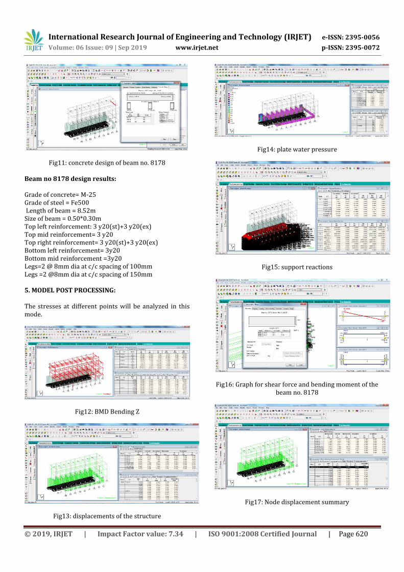
Fig14: plate water pressure
Fig15: support reactions
Fig16: Graph for shear force and bending moment of the beam no. 8178
Fig17: Node displacement summary

International Research Journal of Engineering and Technology (IRJET) e-ISSN: 2395-0056
Volume: 06 Issue: 09 | Sep 2019 www.irjet.net p-ISSN: 2395-0072
© 2019, IRJET | Impact Factor value: 7.34 | ISO 9001:2008 Certified Journal | Page 621
Fig 18: deflection of the structure in post processing
Fig 19: plate center stress 6. CONCLUSION: The results that are obtained from the manual calculations as well as STAAD.Pro analysis for the structural elements are passed out the checks carried out on them including deflection, shear and bending. Selection of different sections for the element is easy and performing the analysis and getting of results immediately in this software. The use of Computer Aided tools in structural analysis and design has been proven to be effective from the results output. It was observed that the time for performing the design work is significantly reduced. However, the software programs can be easily misused without observing proper precautions in the analysis and design procedures which can lead to structural failures, costly disputes and poor performing structures. Thus, this explains the importance of comparison between different software packages and more importantly performing hand calculations for like a floor and comparing for the same floor in the software packages. Therefore, it can be concluded that the structure has fulfilled the requirements of limit state of serviceability and limit state of collapse.
7. REFERENCES: IS:456:2000- Code of practice for plain and
reinforced concrete
IS875 (part-I): Indian standard code of practice for design loads(other than earthquake) for building and structures(part-I) Dead loads.
IS875(part-II): Indian standard code of practice for design loads(other than earthquake) for building and structures(part-I) Imposed loads
IS875(part-III): Indian standard code of practice for design loads(other than earthquake) for building and structures(part-I) Wind loads
IS 1893(Part-I): Indian standard criteria for earthquake resistant design of structures general provisions and buildings
SP:16 : Design aids for reinforced concrete to IS456
SP:34-1987&IS13920: Hand book on concrete reinforcement and detailing
IS 3370-2009: Code of practice for concrete structures for the storage of liquids .part-I – general requirements. Part-II- reinforcement concrete structures.
N .Krishna raju –“Advanced reinforced concrete design”