Embed Size (px)
Citation preview
STROrnJfRG-CARlSOIi JRfPHOrtEMfG.(D~ill9 .)f. ~lliIJl~OO9Jl Ik •~£~ <Cll'il'1f9 ~©. 'If©)~«i)W1f<Q\(Q) 'It
BULLETIN NO. lOll DECEMBER. 1916
Private Branch ExchangeSwitchboards
,i
I 1
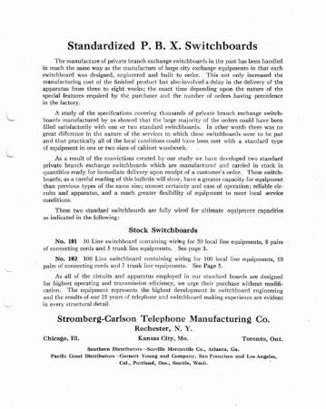
Standardized P. B. X. SwitchboardsThe ma nufactu re of pr ivate bran ch exchan ge switc hboards in th e pa st ha s been handled
in much th e same way as th e manufacture of la rge city excha nge equipmen ts in that eac hswitc hboard was designed , engineered and built t o orde r . This not onl y increased thema nufa cturing cost of the finished product but also involved a delay in the delivery of theap par at us from th ree to eight weeks; th e exac t tim e dep endin g upon the nature of thespecia l features required by the purcha ser a nd th e number of orders havin g pr ecedencein th e fact ory.
A study of the specificat ions cove ring th ousand s of priv at e branch exchange switch boards manufact ured by us showed th at th e lar ge ma jority of th e orders could hav e beenfilted sa tisfac to rily with on e or two sta nda rd switchboa rds. In other word s th ere was nogreat difference in th e nat ure of t he services to which th ese switc hboa rds were to be putand that pract icall y a ll of the local cond itio ns could have bee n met with a standard t ypeof equ ipm~nt in one or two sizes of ca binet woodwork.
As a result of t he convictions crea ted by our st udy we ha ve developed t wo sta ndardpriva te br an ch exchan ge switchboards which are manufactured a nd carried in stoc k inqua nti ties read y for imm ediate delivery upon receipt of a custo mer's ord er . These switc hboard s, as a careful reading of thi s bull et in will show, ha ve a grea ter capacity for eq uipmenttha n previous types of th e sa me size ; utmost cer ta inty a nd ease of opera tion ; reliabl e circuits a nd apparatus, and a mu ch grea ter flexib ility of equipment to meet local serv iceconditions.
T hese two sta nda rd switchboa rds a re fully wired for ult ima te equ ipm ent capacitiesas indic ated in t he following :
Stock Switchboards
No . 101 50 Line switchboa rd conta ining wirin g for 50 loca l line equiprnents, 8 pai rs .of connecting cords a nd 5 trunk line eq uipments . See page 3.
No. 102 100 Lin e switc hboard cont ain ing wiring for 100 local line equiprnents, 10pair s of connec ting cords a nd 7 trunk line eq uipments . See Page 5.
As a ll of th e circ uits an d appa ra tus em ployed in our standard board s a rc designedfor highest ope rat ing and tr an smission efficiency , we ur ge th eir pur cha se without rnodifica tion . Th e equipment repr esent s t he highest develop ment in switc hboa rd engineeringa nd t he results of ou r 25 years of teleph one a nd switchboa rd makin g experience a re evidentin every struct ural det ail.
Stromberg-Carl son Tele phone Manufac t uri ng Co.Roch ester , N. Y.
Chicago, Ill . Kansas City, Mo . Toronto, Onto
So u t he rn Dlstrtbu tor s-e-Scovtll e Mer can t ile Co .• At la nta , Ga.
Pa ci fic Coas t Distributor s- Garne tt Yo ung a nd Company, San Fran cisco a n d Los An geles,
Ca t., Portland. Or e., Seattfe, Wash . .
s rROM BE RG.CAR I.SON n :I .EPIlONE JI A N UFA rnI RI Nr. rO M PANl·
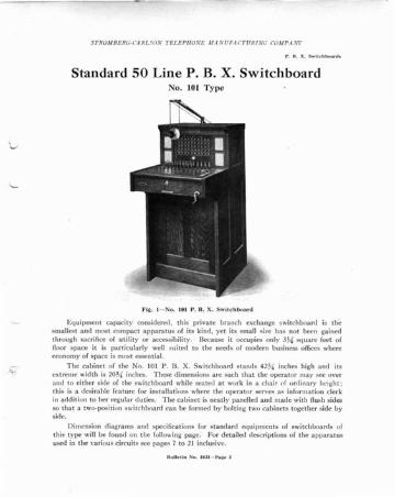
Standard SO Line P. B. X. SwitchboardNo. 101 Type
Fi la. I - S o . 101 P. H. X . S wit c hboa rd
Eq uipmen t ca pac ity conside red, thi s private bra nc h exch an ge switchboa rd is th esma lles t and most co mpac t apparatus of its kind , yet its small size has not been ga inedthr ough sac rifice of utilit y or access ibility . Becau se it occupies only 3}t:l' sq uare feet offloor space it is pa rticularly well suited to the need s of mod ern business offices whereeco nomy of space is most essen tial.
Th e cabine t of th e No. 101 P . B. X. Swit ch boa rd stan ds 42%" inches high a nd itsext reme wid th is 20~{ inches. Th ese d imensions a re suc h tha t th e ope ra to r ma y see overa nd to eit her side of the switchboa rd whil e sea ted at work in a cha ir (If ord ina ry height ;thi s is a desirab le featu re for installati ons where th e ope ra to r serves a s informa tion clerkin addit ion to her regula r du ties. Th e ca bine t is nea tl y pa nelled a nd mad e with flush sidesso that a two-positi on switchboa rd ca n be formed by bolting two ca binets toget her side byside.
Dim ension di agrams a nd spec ifica t ions for sta nda rd eq uipments of switchboa rds ofthi s type will be found on th e following page. For det a iled descr ipt ion s of the appara tusused in th e va rious ci rcui ts see pages 7 to 21 inclu siv e.
8ull~lIn S o . I Oll-Pa ll~ J
S T ROM B E RG-CA RLSON TE LEPflONE MA N UFA Cl' URi NG COM PA .V!'
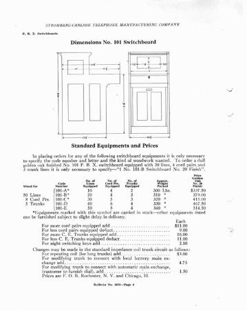
Dimensions No. 101 Switch bo ard
- - ,,..
,.,g.,.- "._-
I
D~D1.-...._
,,'
Sta n da rd Equipments and Pr ices
In placing orders for any of the following swi tchboard equip men ts it is only necessaryto specify th e code number and lett er and the kind of wood work wanted. To order a dullgolden oa k finished No . 10 1 P. B. X. swi tc hboa rd eq uipped wit h 20 lines, 4 cord pa irs a nd3 trunk lines it is only necessary to spec ify-" l No. 101·B Switchboard No. 20 Finish".
P"'~GoJdt'n
No . of No. of No. of Approll . Oak
N~~r F.qL~:;'~ ¥~~p~ ~~~~ ~~:~ ~I':;I:~
50 Lin es l : g : :~: ~g : ~ ~?g I;,bs. S~n:f~8 Cord P rs . IOI-C · 30 5 3 320 « 415.005 Trunks IOI· D 40 6 4 330 " 467.50
101-E 50 8 4 340 " 5 14.50*Equipments marked with this sy mbol are carried in s toc k-s-o ther eq uip ment s listed
ca n be furni shed sub jec t to sligh t de lay in de live ry.Eac h
For more cord pa irs eq uipped add . . . 511.00Fo r less cord pair s equi pped dedu ct. . . . . 9.00Fo r more C. E, Tru nks equipped add . . . . 16.00For less C. E. T ru nks eq uipped dedu ct . 11.00Fo r night switching keys add . . 2.10
Changes may be made in the standard impedance coi l trunk circuit as follows :Fo r repeat ing coil (for long trunks) add . . . . . . . . . . . . . . . . . . . . . . 53.00For modifyi ng trunk to connect with local batte ry main ex-cha nge ad d . . . . . . . . . . . . . . . .. . . . . . . . . . . . . . . . . . . . . . . . . . . . . . . 4.75For modifying: trunk to connect with automatic main exchange,(customer to furn ish d ial), add : . . . . 1.50Prices a re F . O. B. Rochester, N . Y. an d C hicago, III.
S1"ROAtBERG·CA RLSON 1"RI.F.PIIONF. AfA N U F.4C1"URf NG COAfPANJ'
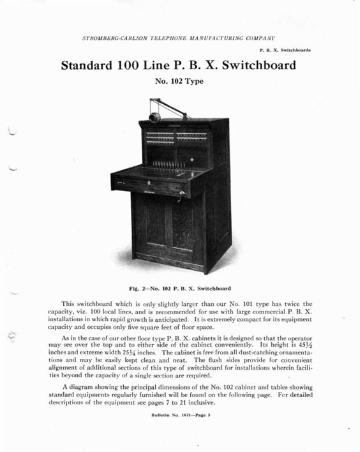
Standard 100 Line P. B. X. SwitchboardNo. 102 Type
\~
FI~. 2- No. 102 P. B. X . Sw it chboard
Thi s switchboa rd which is only sligh t ly lar ger th an our No. 101 type has tw ice thecapaci ty , viz. 100 loca l lines , a nd is recommended for use with la rge comme rcia l P . B. X .inst allati ons in whi ch ra pid gro wth is a nt icipa ted . 1t is ex t remely compact for its eq uipmentca pacity and occupies only five square feet of floor space.
<--- As in the case of our ot her floor type P . B. X . cabinet s it is designed so that th e opera torma y see ove r the top a nd to either side of the cabinet convenient ly . I ts height is 45>iinch es and ex t reme widt h 25J4 inches. The cabinet is free from a ll dust -cat chin g orna mentat ions and may be ea sily kept clean and neat. T he flush sides provide for convenien ta lignmen t of addi tio na l sect ions of th is ty pe of switchboar d for insta llati ons whe rein facilit ies beyond t he ca pacity of a single sec t ion a re req uired .
A diag ra m showing the principal d imen sions of th e No . 102 cabine t and tab les showingstanda rd eq uipme nt s regularly furni shed will be found on th e followin g page. Fe r detaileddescrip tion s of th e eq uipment see pages 7 to 21 inclu sive .
STROMBERG- CARL SON TEL EP HONE M A N UFA CT URI NG COMP ANI'
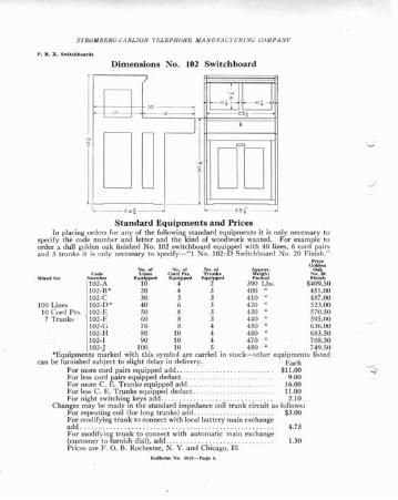
Dimension s No . 102 Sw itc h board
I '·D~ ; D~D- ._I~:=:::::J!L- - t 4 i - - J L- -tof J
Sta n da rd Equi pmen ts a n d PricesIn placing orders for any of the following standard equip ments it is only necessary to
specify the code number and letter and the kind of woodw ork wanted. For examp le toorder a du ll golden oa k finished No. 102 switchboa rd equipped wit h 40 lines, 6 cord pa irs
a nd .l tru nks itNi::~:y neces~~~spec~~~1 ~;~~~~-D SWit;~~~;d No 20 F~~r
102-A 10 4 2 390 Lbs. $409.50102-13* 20 4 3 400 " 45 1.00102-C 30 5 3 410 " 487.00
100 Lines 102-D* 40 6 3 420 " 52.1.0010 Cord Prs. 102-E 50 8 3 430 " 570.507 T runks 102-1' 60 8 3 440 " 595.00
102-G 70 8 4 450 " 636.00102-H 80 10 4 460 " 683.50102-1 90 10 4 470 " 708.50102.J 100 10 5 480 " 749.50
*Equipments marked with this sym bol are carried in stock-other equipments list edca n be furni shed suhject to slight dela y in de livery . Eac h
For more cord pairs eq uipped ad d.. . $11.00For less cord pair s equip ped dedu ct . . . . 9.00For more C. E . T ru nks equipped add . . . . 16.00For less C. E. Tru nks eq uipped dedu ct . 11.00For night switching keys add.. . . . . . . . . .. .. . . . . . . . .. . . . .. . . . 2.10
Changes may be made in the standard impedance coil trunk circuit as follows :.For repea ting coil (for long tru nks ) add .. . . . . . . . .. . . . . . . . . . . . $3.00For modi fy ing trunk to connec t with local battery main exchangeadd . . . .. .. .. .. .. .. .. .. . .. . .. .. .. . . .. .. .. .. .. . .. . .. .. .. .. 4.75For modif ying trun k to co nnect with automat ic main exchange(cus tomer to furn ish dial ), add .... . . . . . . . .. . . . . . . . . . . 1.50Prices are F. O. B. Rochester, N . Y. a nd Ch icago, III.
J
STROMBERG-CARLS ON TE L EPHON E MA N UFA CTUR I NG COM PA NY
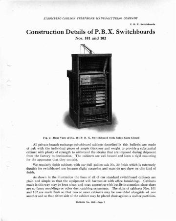
Construction Details of P. B. X. SwitchboardsNos . 101 and 102
FIQ. . J- Rear View of No . 101 P. B. X . Swit c hboa rd wit h Relay Ga te CloP.ed
All priv at e bran ch excha nge switchboa rd ca binets des cribed in this bulleti n a re mad eof oa k with th e indi vidu al pieces of a mp le th ickness ' a nd weight to provide a substa nt ialcabinet with plent y of strength to withsta nd the st rains that are imposed during shipmen tfrom the factory to destin ation . Th e cabinets are wen braced and form a rigid mountingfor the apparatu s that they contain.
We regula rly finish ca binets with our d ull golde n oa k No, 20 finish which is ext remelydurable for switchboard use becau se slight scratches and mars do not show on this kind offinish .
As shown in the illustration the lines of all of our standard switchboard cabinets areplain and simple so that the equipment will harmonize with office furnishings. Cabinetsmade in this way may be kept clean and neat appea ring wit h hut littl e-attention since thereare no fancy mouldi ngs or other d ust -cat ching ornamen ts. The sides of cabi nets Nos . 101and 102 are mad e flush so th a t t wo or more ca binets ma y be asse mbled alongside of onea nother and so that either side of th e ca binet may be placed close again st a wall or pa rt ition.
STROMBERG·CA RL SON TELEPHONE MA NUFACT URING COMPANY
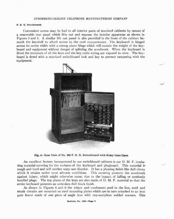
Convenient access may be had to all interior parts of standard cabinets by means ofa removable rear panel which lifts out and expo ses the interior apparatus as shown inFigures 3 and 5. A similar lift out panel is also provided in th e front of th e cabinet beneath th e keyshelf to afford access to th e cord compart ment . Th e keyboard is hingedacross its entire width with a strong piano hinge which will susta in the weight of the key.boa rd and equipment withou t danger of split t ing th e woodwork . Wh en the keyboard islift ed th e term inals of all t he keys and the key cable wiring are exposed to view. Th e keyboard is fitted with a sta nda rd switc hboa rd lock and key to prevent tampering with theequ ipme nt.
Fig. 4-Rear View of No . 101 P. B. X . Switchboard with Relay Gate Open
An excellent feature incorporated in our switchboard cabinets is our D . M . F. insulating material cove ring for the surfaces of the keyboard and plugboard. Thi s mat erial istough and hard and will neith er warp nor discolor. It has a pleasing finish like d ull ebonywhich it retains under most adverse conditio ns. Th is covering protects the woodwor kagain st injury , which might otherwise occur, due to the impact of falling or careless lyhand led plugs. Th e top pla tes of the keys a re a lso made of D. M. F. mat erial so th at t heent ire keyboard present s an unbroken d ull black finish.
As shown in Figures 4 and 6 the relays and condensers used in the line. cord andtrunk circuits are mounted on steel mounting plates which are in turn att ached to an irongate frame made of one piece of angle iron with oxy -ace ty lene ·welded corners. T his
Bu lletin No . tOll - Faile 8
S TROM BE RG-CA RLSON TELE PHON E MA NU FA CT URI NG COMPA N Y
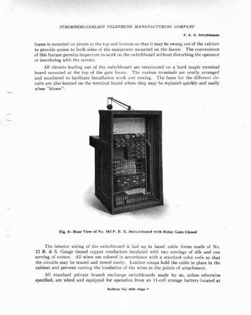
frame is mounted on pivot s at the top and botto m so that it may be swung out of the cabinetto provide access to both sides of the equipment mounted on the frame. The convenienceof this fea ture permits inspec tors to work on the switc hhoa rd without d istu rbin g the operatoror interfering with the service.
All ci rcuit s leaning out of the switchboa rd arc terminated on a hard maple terminalboard moun ted at the top of the gate frame. T he various terminals are neatly arrangedand numbered to facili tate installation work and testing. The fuses for the different circuits a re also loca ted on t he te rmina l board where t hey ma y be replaced quickly a nd easilywhen "blown" ,
FIg. 5-Rear View of No. 102 P. B. X. Swit chboa r-d with Relay Gat e Clos ed
T he interior wiring of the switchboard is laid up in laced cable forms made of No.22 B. & S. Gauge tinned copper conductors insulated with two servings of silk and oneserving of cotton. All wires are colored in accorda nce with a standard color code so thatthe circ uits ma y be t raced and test ed eas ily. Leather st ra ps hold th e cab le in place in thecabinet and prevent cuttin g the insulation of the wires at the points of attachment.
All sta ndard privat e branch exchange switchboards made by us, unless o therwisespecified , a re wired a nd eq uipped for operat ion from a n II -cell storage ba tte ry locat ed at
Bull~t ln No: lOll- h al' .,
S TROMBERG-CA RLSON TEL EPH ON E MA N UFA CT UR1NG COMPANY
the private branch exchange or from batt ery current of equal voltage supplied over batt eryleads from the main exchange. Th e sta ndard boa rds a re a rranged for t runk circuit oper ation in connection with "Central Energy" main exchanges but can be supplied with outtrunk eq uipm ents for isolated systems or with modified trunks for P. B. X . sys te ms ope ratedin connecti on with magnet o or aut omati c main exchanges .
A detailed description of the equipme nts used in the various circuit s and of theiroperat ion will be found in the followiog pages.
Fig . 6--Rear View of No. l Ul P. H. X . Sw nchboard with Re lay Gate Open
Standard Line Circuit EquipmentEac h equipped line circuit in a standa rd No. 101 or No. 102 P. B. X . switchboa rd is
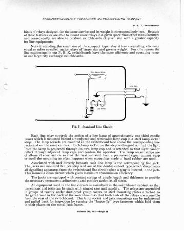
equ ipped with a compact type line relay, line lamp with numbe red lamp cap, and th e associa ted doub le cut-off type line jack. Th e circuit used is shown in Figure 7. a t ype ofline circuit which we have used successf ully for many years. Thi s circuit ,since it conta insa line relay, operates positively and displays a line signa l of uniform brilliancy in connectionwith both long and short lines.
T he relay used in this line circuit is our compac t type relay which we regularly use inour sta ndard Central Energy multipl e switch boards for city exchange service. It is the mostcom pac t relay made . It occup ies only one-third of the space usually ta ken up by other
Bulletin No . 10U-Palle 10
STROMBERG-CARLSON TELEPHON E MA N UF,t CT URI NG COMP1NY
kinds of relays designed for the same service and its weight is correspondingly less . Becauseof these features we are able to mount more relays in a given space than other manufacturersand consequently are able to produce switchboards of given size with a greater capacityfor line equip ments.
Notwithst an d ing th e small size of the compac t type relay it has a signalling efficiencyequal to other so-ca lled major relays of larger size and greater weight. For this reason theline eq uipments in our P. B. X . switchboards have the same efficiency and operating rangeas our large city exchange switchboa rds.
}·i!t . 7-Sta ndard LIne Circui t
Eac h line relay controls th e actio n of a line lamp of a pproxima tely one-t hird ca nd lepnwer which is moun ted beh ind a numbered a nd rem ovab le la mp ca p in a steel la mp socke tstrip. Th e lamp sockets are mounted in the switchboard face above the corresponding linejacks a nd on th e same cen ters. Eac h lamp socket on th e st rip is designed so th at th e lightfrom th e la mp is projected through it s own lam p ca p and is screened so that light cann otreflect thr ough adjacent lam p ca ps a nd confuse the ope rator . Th e la mp socket s trips arcof all -met al construction so that the heat radiated from a permanent signal cannot warpor swell th e mou nti ng as ofte n ha ppens when moun tings mad e of hard rub ber a rc used .
Associat ed with a nd d irectly benea th each line lamp is t he correspnnding line jac k.T he jacks a re mount ed ten per strip a nd a rc or th e doubl e cut-o ff type which d isconn ect sall signa lling a ppa ra tus from t he switc hboa rd line circuit when a plu g is inserted in th e ja ck .This insures a clean circuit which gives maximum transmission efficiency .
T he jacks a re equipped with contac t springs of ample length and thi ckn ess to providethe necessary permanent adjustment and positive action at all times.
All equipmen t used in th e line circui ts is asse mbled in th e switc hboa rd cabi ne t so t ha tinspec tions and tests can be made with utmost ease and rapidity . Th e relays are assembledin groups of twent y under d ust -proof group covers on stee l mounting plat es a t tached tot he ga te fra me in t he bac k of th e switchboa rd so that bo th ends of th e rela ys a re accessiblefrom th e rear of th e switchboa rd . T he la mp socket a nd jack mountings can be unf ast enedan d pulled back for inspection by turning the " butt erfly" type fast eners which hold themin th eir places on the met al jack fra me.
Bulletin No. IOll - Pa._ II
STROMBER G-CARLSON TEL EP llONE MA N UFA CT URI NG COM PANY
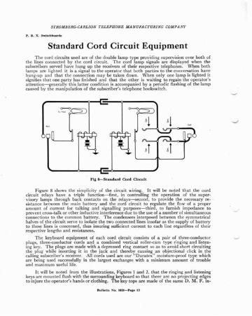
Standard Cord Circuit EquipmentT he cord circuits used are of the double lamp type prov iding supervision ov er both of
th e lines connected by the cord circuit . Th e cord la mp signa ls are d isplayed when th esubscribers served hav e hung up the receivers of their respective telephones. \Vhen bo thlam ps arc lighted it is a signal to the operator that both parties to the conv ersation havehung-up a nd t ha t t he connection ma y be tak en down. W hen only one lamp is lighted itsignifies th at one party has finished a nd th a t the other is wait ing to rega in the opera to r' sattention-generally this latt er condition is accompan ied by a periodic flashing of the lampca used by th e manipulation of th e subscriber's telephone hookswitch.
Fig 8-Standard Cord Circuit
Figure 8 shows the simplicity of the circuit wiring. It will be noted that the co rdcircuit relays have a triple functi on- first, in co ntrolling the operation of the superv isory ta mps through bac k co ntac ts on the relays--second, to prov ide the necessary resistance bet ween the main batt ery and the cord circuit to regulate the flow of a properamount of current for talking and signalling purposes-third, to furnish impedance toprevent cross- talk or other induct ive interference due to the use of a number of simultaneousconnect ions to the co mmon batt ery . Th e condensers int erposed betw een the sy mmetricalhalves of the circuit serve to isolate the two connec ted lines insofar as the supply of batt eryto these lines is concerned, thus insuring sufficient current to each line regardless of theirrespective lengths and resistances.
Th e keyboard equipmen t of each cord circuit consists of a pair of three-cond uctorplugs, th ree-con duct or cords and a combined ver tical roller -ca m t ype ringing and listen ing key. T he plugs are made with a depressed ring co ntact so as to avoid short circuitingth e plug while inser ting it in the ja ck a nd th ereby ca using a n objectiona l click in t hecalling subscriber's receiver. All cords used are our "Dura tex" moisture-proof type whichare being used successfully in the largest exchanges with a minimum amount of troubleand maxim um useful life.
It will be noted from th e illus tra tions, Figures 1 a nd 2, th at th e ringing and list eningkeys a re mounted flush with the sur rounding keyboard so th at th ere are no projecting edgesto inj ure the opera to r's ha nds or clothing. Th e key tops are made of the sa me D. M. F_ in-
S TROM BERG-CARLSON TE L EPllONE MA N UFA CTURING COMPA NY
sula ting mat erial as th e covering on the keyshelf woodwo rk to pr esent a plea sin g a nd uniformfinish which ret ain s its lustre a nd resists wear . Each key is fast ened to t he stee l key mounting
-Ira rne indepe nde nt ly of other adjo ining keys to facili ta te easy removal of th e key un it bysimply loose ning two screws. All wir es run to th e keys ,in ind ividu al cab les with out crossst ra p wires so th at a key ca n be pulled up and ou t of keysh elf for inspect ion.
Th e keys in th emselves are positi ve acting a nd a re des igned so that continued use wiltnot a ffect th eir ope ra ting q ua lit ies. Th e sp rings a re lon g an d hea vy an d will ret ain th eiradjustm ent in service indefini tely. As the springs a rc mounted ver t ically du st that mi gh tsift th rou gh th e top of th e kevshelf ca nno t se tt le on th e spri ngs nor lod ge be tween th econtact poin ts . - .
Unequipped key a nd plug space; ar e d ril led a nd filled wit h appa ra tus bla nks so t ha tad d it iona l equ ipment may be installed at any ti mc wit h a minim um a mo unt of work.
An gle a rmature relay s of th e sa me type used in our main excha nge swi tch boa rd an dcircuits a re used excl usi vely in the cord cir cuits of our P. B. X . swit chboards. Th ese rela ysa re ext remely sensitive a nd efficient so that they hav e a wide ran ge and a rc th oroug-hlyrelia ble in th eir ope ration. Th e imp ed a nce of the wind ings a nd the shield ing of th e indi vid ualma gnet ic field of eac h pa ir of rela ys a re designed to pr event the sligh test cross-talk betweenth e severa l cord circuits .
All relays a nd co nde nse rs used in th e cord circ uits ar e mounted in the back of th eswitc hbo a rd on stee l mo un ting pla tes attached to the swinging gate fram e to prov ide co mplet e access ibility. All a ppa ra tus mou nted in th is way is ste nci lled with a n identifyin gnumbering and lett erin g to facilita te inspe ct ion an d tes ts.
Standard Trunk Circuit Equipmentl owil~~I;~~~~~~~1 tr unks of our sta nda rd ty pes a rc preferr ed for P . B. X . service for the foI
l. Th ey per mit th rough supervision from P. B. X . teleph one to t he ma in exc hangea nd show simulta neo us di scon nect signa ls before both th e Ce ntra l and P . B . X . ope ra to rs.
2. T hey elimina te t runk circuit complica tion s from th e local cord circui ts th at a rcreq ui red when jack -end trunks a re requ ired .
3. Th ey increase th e ava ilabilit y of local cord s for strictly local connec tion s.4. Th ey perrni t con venie nt connect ions of local lines to t ru nk lines for thro ugh night
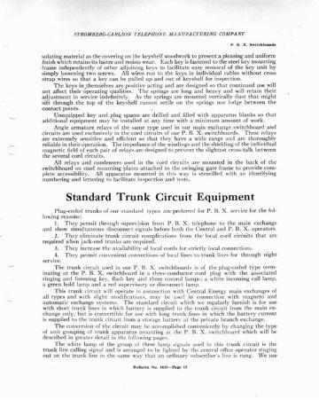
se rvice .T he trunk circ uit used in our P . B. X . switchboa rds is of the plu g-ended type term
ina t ing at th e P . B. X . switc hboard in a three-conductor cord plug with the assoc iatedrin ging an d listeni ng key, flash key and three control la mps : a white inco ming ca ll lam p.a green hold lam p and a red supe rvisory or d isconnec t la mp.
Thi s tru nk circuit will opera te in connec t ion with Centra l Energy main excha nges ofall types a nd with slight modifi cati ons . may be used in connec t ion with magneto a ndauto mati c exchange sys tem:". T he s ta nda rd circuit which we regula rly furni sh is for usewith short t runk lines in which batt er y is supplied to th e tr un k circ uit from th e ma in excha nge only, hut is co nvert ible for 1I~ with long trunk lines in which t he batter y currentis supplied to the trun k circu it from a st ora ge ba t terv a t the private branch exchange.
Th e conversion of the circuit may he accomplished co nve nient ly by cha nging the typeof un it group ing of t run k a ppa ra tus mount ing a t the P. B. X. swi tchboa rd which will bedescribed in grea te r detail in th e following page....
T he whi te la mp of th e group of three la mp »iguuls used in th is t runk circuit is th et runk line cal ling signal a nd is arranged to he light ed hy th e centra l office ope ra tor ring ingout on t he tr unk line in th e sa me wa y that an ord ina ry sub scriber 's line is rung. \Ve usc
S TRO MBERG-CARLSON TELEPHONE MA N U FA CT URI NG COMPA NY
in this trunk circui t our No. 300-X type rin g-up relay which has a n a lte rna ting currenttype of inerti a a rmature. After being pulled up by th e acti on of th e ringin g current it ismechanically lat ched in its oper ated posit ion su th at the la mp remain s lighted until th eP. B. X. opera tor a nswers the call by operat ing her listening key. Th is function is posi t ivein its operation and the signa l ca nnot be relea sed by reverse curren t act ion in the relay asofte n happens when a magneti c lockin g ac tion is used .
\Vhen th e P. B. X. opera to r thr ows her list en ing key in answe ring -an incomi ng callfrom cent ra l, th e trunk is au toma tica lly " held" a nd the green lamp ligh ts and rem ainsligh ted until th e P. B. X . loca l station an swers. The presence of this signa l a lways indica testha t t he t ru nk is being held by some act of t he opera to r and sign ifies a n off-norma l cond itio n:for exa mple, it relights when t he P. B. X . par ty " ha ngs up" if the trunk list ening key isaccide ntly left in its opera ted positi on . . It will also flash under the sa me condit ions if th eP. B. X . pa rty moves the hook on his te lephon e up a nd down .
Flit . 9-Standard Tr u nk C·lrc ult, Im ped a n ce Coil Type
Th e green la mp does not light whe n t he ope ra to r monitors a connect ion . \Vhen incoming trunk line ca lls a re not comp leted th rough to a P. B. X. station th e operato r mayrest ore th e gree n signa l by ope ra ting her trunk circuit ringing key .
The red la mp in th e trunk circuit is a di sconn ec t or supervisory signa l wh ich lightswhen th e P. B. X . party han gs up his receiver aft er completing a conversa tion. Thi s acti onalso opera tes the superviso ry la mp a t th e central office so th at th e trunk line is clea redquick ly by bot h ope rators. T he opera tion of th e t hree trunk la mps a re ind epen den t ofone another so th at a combina tion of red a nd white lam ps lighted a t th e sa me tim e wou ldindi cat e a disconn ect ion to be mad e for some P. B. X . party and new incomin g ca ll fromcent ra l. Th e circuit is so a rra nged t ha t th e la mps always signify th e sa me ope ra t ionsregardl ess of th e ope ra ting cond itio ns that exist a t th e tim e. Furt her information regarding th e sequence of ope rat ions in handling of trunk line calls will he found on page 30.
An ent irely new feature of ext raordinary va lue to telephone compa nies a nd otherusers of switc hboards of th is type is our meth od of grouping a nd mounting th e rela ys,conde nsers, repea tin g coils , etc ., used in eac h tru nk circ ui t on a rem ovahl e an d int erchan ge.ab le moun tin g pla te which is, in tu rn , moun ted on th e gate fram e in the rea r of the switc hboa rd. All of th e a ppa ra tus on th e mounting plat e is wired togeth er in accord an ce withthe circuit requirement s a nd terminat ed on a screw-connec tion terminal block on th e endof t he circuit plat e. Th e P. B. X . switchboa rd cabinet is wired with a cab le which provides
BuUedn No. IO:U-hQe 14
STROM BE RG-CAR LSON TE LEPHONE MA N UFA CT URING COMP ANY
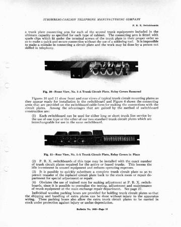
a trunk pla te connec ting a rm for each of th e several tr unk equipments included in th eult ima te capacity as speci fied for each type of ca binet . Th e connecting a rm is fitt ed wit hspade clips which fit under th e terminal screws of the t run k plat e in thei r prope r orde r soas to mak e a q uick and secure connec tio n with out th e use of a solde ring tool. It is impo ssib leto make a mistak e in connec ting a circuit plate a nd the work ma y be done by a perso n notskilled in telephon y.
FIg. t 6--Fr ont View, No. t · A T runk Cir cui t Pl at e , Relay Covers Removed
Figures 10 a nd 11 show front a nd rear views of typi ca l tr unk circuit mou ntin g pla tes ast hey a ppea r read y for insta llat ion in th e switchboa rd and Figure 6 shows th e con nect ingarms that are provi ded on th e switchboa rd ca ble form for mak ing t he connectio ns with th ecircuit plat es. Among t he adva nta ges tha t ar e ga ined by the met hod of switchboardconst ruction a re :
(1) Eac h switc hboard ca n be used for eithe r long or short tru nk line serv ice bythe usc of one type or the ot her of our two sta nda rd trunk circuit pla tes which a reinte rcha ngea ble for use in the sa me switchboard.
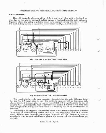
Fig. ll-Rear View, No. I -A T ru n k Ci rc ui t Pl a te . Rel ay Covers in Pl ace
(2) P. B. X . switc hboa rds of th is type may be installed wit h the exac t num berof tr unk circuit pla tes requ ired for t he act ive or leased t runks . T his lessens th eidle inves t ment in unused equipment a nd redu ces operating expe nses .(3) It is possible to qui ckly subs tit ute a comp lete trun k circuit pla te so as t opermit t ra nsfe r of t he replaced circuit pla te bac k to the stoc k room or repai r de·par trnent for specia l adj us tment or repair.(4) Obvia tes th e use of t rai ned men for maki ng ad just ment at P. B. X. switc hboard s, since it .is poss ible to cent ra lize t he testing, adj ust men t an d ma intenanceof t runk equ ipm ent a t th e main excha nge re pai r depa rtm ent . Seepage 27.In dividual woode n pac king boxes a re provided for holding trunk circuit plat es so tha t
t he shipping a nd handling of ext ra plates ca n be do ne witho ut inj ury to t he ap pa ra t uswiring. Th ese packing boxes a lso a llow the ext ra trunk circui t pla tes to be ca rried instoc k under prot ect ion agai nst injury or und ue depr eciati on .
Bulletin No . IOn - Pate 15
S TROM BERG-CA RLSON TELEPHONE MA NUFACTURING COMPANY
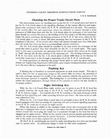
Figur e 12 shows t he schematic wiring of th e trunk circuit plat e as it is furni shed. forshort line serv ice wherein t he tru nk talkin g bat tery is furni shed from th e main excha nge.Figure 13 shows th e wiring of a similar circuit plat e a rra nged for long line serv ice in whichthe tr unk talking bat tery is supplied to th e circuit at t he P.•B. X . switchboard .
F ig. 12-Wiring of No . I-A T runk Circ u it Pl at e
Fi g. 13-Wlrinl1of No. 2-A Trunk Circu it Pla te
Th e two circuit s have the sa me operating characterist ics, th e main difference beingtha t t he No. I- A circuit plat e for shor t line serv ice is equipped with an impeda nce coil,whereas the No. 2- A circuit plat e for long service is fitted with a repeat ing coil. In case ofnecessity No. I- A circuit plat es ma y be conver ted int o th e No. 2-A type or vice-versa 'witha few cha nges in t he wiring a nd subs titution of a repeating coil for an impedance coil orvice-versa .
Th e wiring of both t ypes of t his sta nda rd circuit is such th at it is impossible .to releaseth e t run k at the centra l office by ca reless han dling of t he trunk plugs at th e P. B. X. switchboard . T his is a most imp ortant feature since man y cal ls a re " lost " becau se of imp roperoperat ion in ot her types of switchboa rds wherein th e necessar y circui t sa feguards a re notpro vided .
BuU etin No . IOll-Paae 16
-:»
S TROMBERG-CA RLSON TELEPHONE MANUFA CT URI NG CO_llPA NY
- Choosing the Proper Trunk Cir cuit PlateTh e det ermin ing fact or for decidin g when to use th e No. I - A circuit plat e and when to
use th e No. 2- A circuit plat e is the signa lling efficiency of th e cen tra l office line a nd supervisory relay equ ipm ent with which th e P. B. X . switc hboa rd is to be used . For exa mple:if th e cent ra l office line an d supervisory rela ys are ad justed to ope rate thr ou gh a tot alresistance of 1000 ohms t hen with th e No. I-A circui t pla te th e resist an ce of th e trunk linewires should not exceed 500 ohms as t he holdin g coil in this trunk is of 500 ohms resist an ce.Under the a bove conditions th e limiting resistance of th e P. B. X . line wires, when t he No.t- A circuit plat e is used. is about 250 ohms assumi ng th at the resista nce of th e P. B. X .telep hone is ISOohms. If t he central office relays will ope ra te through more th an 1000 ohmsthen th e trunk line wires ca n ha ve a correspo ndi ngly greater resista nce.
Th e No. 2-A circuit plate sho uld be specified in all cases where th e resist an ce of th etrunk line wires is grea ter tha n th at .all owa ble for the No. I-A circuit plat e. T he upperlimit in thi s case is pract ically the opera t ing limit of th e centra l office rela ys as th e trunk
'- is " held" th rough t he 40 ohm windin g of th e repea ting coil. The limiting resista nce of th eP. B. X . line wires wit h t he No . 2-A circuit plat e is abo ut 1000 oh ms as t he battery fortr unk line t ran smi ssion is fed thro ugh a repea ting coil a t the P. B. X . switc hboa rd .
. T o assist purch asers in choosing th e proper circuit pla te to meet a ny given local conditi ons our Engineering Department will furni sh upon requ est recommend at ions a nd adviceas to th e most efficient eq uipmen t to be used .
Plas h ing KeyA flashing key is furni shed as sta nda rd equipment in eac h trunk circuit. Thi s key is
used to flash th e line or supervisory la mps a t th e cent ra l office to a tt rac t the attentio n ofthe main exchan ge opera tor for recalls or for ot her pu rposes wherein t he assistance of themain exchang e ope ra to r is required . Th e flashin g key is non- locking a nd the refore ca nno trend er th e trunk inopera t ive t hrough failur e of the opera to r to restore t he key handl e toits proper position.
Nigh t Swi tc h ing KeyWith the No. I-A Circuit P la te night serv ice ca n be given to a ny P. B. X . loca l line
by mere ly inserting the trunk plug in th e P. B. X . local line jack and switching off t heP. B. X . battery supply. T his extends the P. B. X . loca l line to the main excha nge.switc hboa rd, so t hat signa lling and other ope ra ting functi ons.are di rect-the sa me as for a n ordi nary subsc riber's line.
Wh en the No. 2-A Circuit Pla te is used t hen it is advisable to have t he P. B. X . switch boa rd eq uipped with a key for cutt ing the repea tin g coil a nd assoc ia ted signalling a ppa ra tusin th e P. B. X. tr unk out of circuit for night service .
Wh en thi s fea t ure is ad ded to t he sta nda rd trunk circuit th e unequi pped side of th eRash key is equipped with conta ct sprin gs so t hat when th is key is opera ted with it s hand let hrown toward th e t runk plug th e trunk line is connected through to th e loca l line t hat isplugged-up for night service. Wh en t he key ha ndle is in its norma l upri ght positi on for da yserv ice th e t runk circuit perfor ms it s norm al fun ctions. A lett ered instr ucti on ca rd along side of t he trunk circuit keys explains th e use of all keys.
All th e P . B. X . switchboa rds a re wired for night switching keys but th ey ar e furnishedonly on specia l order. An ad di t ional cha rge is made for thi s ext ra eq uipment .
S TRO M BE RG·CARLSON TE LE PHONE MA N UFA CT URI NG COM PANY
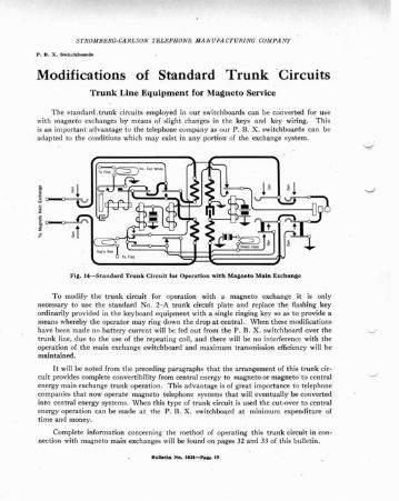
Modifications of Standard Trunk 'CircuitsTru n k Line Eq u ipment for Ma gne to Service
The sta ndard. t runk circuits employed in our switc hboa rds ca n be con verted for usewit h magn eto excha nges by mea ns of slight cha nges in t he keys and key wirin g. T hisis an import an t advantage to the telephone compa ny as our P . B. X . switc hboa rds ca n beada pted to the conditions which ma y exist in an y port ion of th e excha nge sys te m.
F lit. 14-St andard T ru n k Ci rcu it for Opera tio n with Ma llneto Main Excha nge
T o modif y th e t runk circuit for ope ra tion with a magnet o excha nge it is onlynecessary to use th e sta nda rd No. 2- A tr unk circuit plate a nd repl ace th e flashing keyord ina rily pr ovided in th e keyboard equipment with a single ringing key so as to provide amean s whereby th e opera to r ma y rin g down th e drop at cent ra1. \Vhen th ese modifi cat ionshav e been mad e no battery current will be fed out from th e P . B. X . switchboa rd over th etr unk line, du e to th e use of th e repeat ing coil, a nd th ere will be no int erference wit h th eopera t ion of th e mai n excha nge switc hboa rd a nd maximum tr an smission efficiency will bema intained .
It will be noted from t he preceding paragraph s th at th e ar ra ngement of thi s trunk circuit prov ides complete convertibility from centra l energy to magneto or magneto"to cent ra lenergy main excha nge trunk opera tion. Th is adva ntage is of grea t importa nce to te lephon ecompa nies th at now opera te magnet o telephone syste ms th at will event ually be convertedint o centra l energy sys te ms. \Vhen thi s type of trunk circuit is used th e cut-over to cent ra lenergy opera tion ca n be made a t th e P. B. X . switc hboa rd at minimum expenditure oftim e and money.
Compl ete inform ation concerning th e method of ope ra ting thi s tru nk circ uit in connecti on with magn eto main excha nges will be found on pa ges 32 and 33 of thi s bull etin .
S TRO MBERG-CARLSON TELEPHONE MA N UFA CT URI NG COMPANY
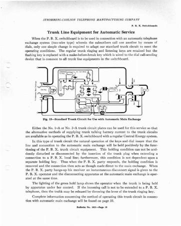
Trunk Lin e Equ ipmen t for Au tomatic Service
When th e P. B. X . switchbo ard is to be used in connection with an auto matic telephoneexchange system (two-wire type) wherein th e subscribers call one an oth er by mean s ofdials, only one simple change is required to adapt our standard trunk circuit to meet theoperating conditions. The regular trunk ringing and listening keys are retained but theflashing key is replaced with a make-before-br eak key which is wired to th e dial call-sendingdevic e that is common to all trunk line equipments in the switchboard.
Fill. 15-Stan dard Trunk Circu it for Use wit h Auto ma tic Main Exch ange
Eith er th e No. I- A or No. 2- A trunk circuit plat es can be used for t his serv ice so thatthe alte rnative meth ods of supplying trun k ta lking bat tery cur rent to the trun k circuitsa re avail abl e as in opera ting th e P. B. X. switchboa rd with a regular Cent ra l Energy sys tem.
In th is type of trunk circuit the na t ural operation of the keys and dia l insure that th eline and connection to the automatic main exchange will be held positively by the functioning of the P. B. X . .trunk circuit eq uipment. Th is holding cond ition can not be acciden tly distu rbed or disconn ect ed by th e insert ion of th e trunk plug when extending aconnect ion to a P. B. X . local line ; furthermore, this condition is not dependent upon asepa ra te holding key. T hus when the P. B. X . pa rty respond s, the holdi ng condi tion isremoved and the connection then acts as though made direct to the main exchange. \Vhenthe P. B. X . party hangs-up his receiver an instantaneous disconnect signal is given to theP. B. X . operator and the disconnecting apparatus at the automatic main exchange is operated a t th e sa me tim e.
The lighting of the green hold lamp shows the opera tor when the trunk is being heldby appara tus under her contro l. If th e incomin g call is not to be extended to a P. B. X.teleph one, th en the truhk may be released by throw ing th e lever of the t runk ringing key.
Complete information concerning the method of operating this trunk circuit in connection with auto matic main exchange will be found on page 33.
Bulletin No. IOn-hae .,
S TROMBERG-CARLSON TE LE PHONE MAN UFA CT URI NG COA/PAN!'
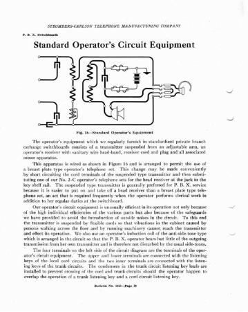
Standard Operator's Circuit Equipment
c-E-6--_~-------
Ftg, 1ft-S tandard Operat or ' s Equipment
Th e opera to r's equipment which we regular ly furn ish in sta nda rdi zed pri vat e br a nchexchan ge switc hboa rds consists of a tran smitt er suspe nded from a n adjusta ble a rm, anopera to r's receiver with sanita ry wire head-ba nd , receiver cord and plug a nd all associa tedminor a ppa ra t us.
Thi s appa ra tus is wired as sho wn in Figure 16 a nd is a rra nged to pe rmit t he use ofa br east pla te typ e opera to r's telephone set. Th is cha nge may be mad e conve nient lyby short circuitin g th e cord termin a ls of th e suspended type tr a nsmitt er a nd then subs t itu ti ng one of our No. 2-C ope ra to r's telephone sets for th e head receiver a t t he ja ck in th ekey shelf rai l. Th e suspended type tr a nsmitt er is genera lly preferred for P. B. X. servicebecau se it is eas ier to put on a nd tak e off a head receiver th an a breast pla te ty pe telephone set , a n ac t t ha t is required frequen tly when the opera to r per forms clerica l work inaddit ion to her regular du ties a t t he switc hboa rd .
Our opera to r 's circuit equipment is unusually efficien t in its oper ati on not on ly becaus eof t he high ind ivid ual efficiencies of th e va rious parts but also beca use of the sa feguard swe have provided to avo id th e int rodu ction of outs ide noises in the circuit. T o this endthe tran smitt er is suspended by flexible cord s so th at vib rati ons in t he ca binet ca used bypersons walking ac ross th e floor a nd by runni ng machi nery ca nnot reach the t ra nsmit tera nd effect its opera tion. \Ve also use a n opera to r 's induc tion coil of th e a nti-side -to ne typ ewhic h is a rra nged in the circu it so tha t t he P. B. X . opera to r hear s but little of th e outgoingt ran smission from her own tr an smitter a nd is th erefore not disturb ed by th e usual side-tones.
T he four termi nals on the left side of t he circ uit diagram a re the term inals of the ope rat or's circuit eq uipm ent . T he upp er a nd lower termina ls a re connec ted wit h t he list eningkeys of the loca l cord circui ts a nd the two inner terminals a rc connected wit h the listening keys of th e t ru nk circui ts. Th e conde nse rs in the tr unk circuit listening key lead s a reinsta lled to prevent cross ing of the cord a nd tr un k circu its sho uld the opera to r happen tooverla p t he ope rat ion of a t runk listen ing key a nd a cord circuit listen ing key.
8 ull e cln .No. IOll-~ae _:lO
S TR OM BERG·CA RLSON T ELEPHONE MA N UFA CTU RI NG COM PA NY
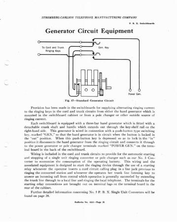
Generator Circuit Equipment
To Cord and TrunkRinging Keys
;--o--J . Gen. Key
Fi ll. 17-5tandard Ge ner a to r Circ u it
Pr ovision has been mad e in the switchboa rds for supplying a lte r nat ing ringing curren tto the ringing keys in the cord a nd trun k circuit s from either t he ha nd genera to r which ismounted in the switchboa rd ca binet or from a pole cha nger or ot he r outs ide source ofringing curren t.
Eac h switchboard is eq uipped with a t hree- bar ha nd generator which is fit ted wit h adetach able cra nk sha ft and han dle wh ich extends out t hroug h th e key-shelf ra il on theright -ha nd side. T his generator is wired in cOIlnect ion with a push -but ton ty pe switchingkey, ma rked "GEN," so that th e hand generat or is in circui t when t he button is locked inth e " out" posit ion. \Vhen this push -bu tt on key is depressed so as to lock in th e " in "posi t ion it di sconn ect s the ha nd gen erat or from th e ringing' circuit a nd co nnec ts it th roughto th e power genera tor o r pole cha nge r term inals mark ed " PO\VER G E N." on th e term ina l boa rd in the back of th e switchboa rd .
\Viring is included in th e cord a nd trun k circuits to provide for the a utoma tic sta r t ingan d stopping of a single un it ringing co nver te r or pole cha nger such as our No.5 Co n- ·ve rte r to economize th e consumpt ion of th e opera t ing battery . Th is wirin g and th eassocia ted equ ipment is designed "to sta rt th e ringing device t hrough t he usc of a sta rt ingrelay wh enever the ope ra tor inser ts a coni circuit ca lling plug in a line jack prev ious toringing th e co nnec ted sta t ion a nd whenev er she ope rat es her t runk line list enin g key toan swer an incom ing ca ll from centra l wh ich ope ra tion is genera lly succeed ed by extend ingth e tru nk line t hro ugh to a local line a nd ringing the loca l te lephone . The termina ls for th esta rt ing relay connec tio ns a re brou ght out on te rm inal lugs on the termi nal boa rd in therea r of the ca binet.
Further det ai led informat ion concerning No.5 P. B. X . Single Un it Conve rters will befound on pa ge 28.
S TROMB ERG-CARL SON TELEPHON E MA N UFA CT URI NG COMPA NY
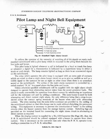
Pilot Lamp and Night Bell Equipment
Flit. 18-Standard Night Alarm Circuit
T o relieve the operator of the necessity of watching all of the signals we equip eac hsta ndard switchboa rd with a pilot lamp which is mounted in the piling block beneath t heline jacks and lamps.
T his pilot lam p is lighted whenever a call is indicat ed by a local or t run k line lampor whenever a signal for a disconnection "is indicated by a supervisory lamp in either atrunk or cord circuit. Th e lamp remains lighted as long as there is an unan swered signalon the switchboard.
T he relay which opera tes the pilot lamp is equipped with an ex tra pair of contac tswhich are wired to close a night alarm buzzer circuit so as to give an audible as well as avisible signal to the operator for use at night or ot her times when there is no att endan tsea ted a t t he switc hboard . T he ac tion of t he night alarm equipme nt is controlled by aswitch marked "N . A. " in a panel above the line jacks and lamps. .
Unless otherwise specified switc hboards will be supplied with the night alarm circuitdesigned to operate from alternating current taken from the power generator leads. T hecircuit is easily convertible for operation from direct current by substituting an impedancecoil for the resistance coil and by adding a condenser. Th e same buzzer is used for bothalternating and direct current night alarm, the only difference being that a strap is connected across the contac t spring terminals of the buzzer when used with alternatingcurrent. Th e wires running from the noise-k iller condenser are provided in the cabling oft he switchboa rd cabinet so tha t this cha nge can be made without d ist urb ing t he perma nentwiring. T his equipment is necessary to prev ent the introducti on of " noise" in the talkingcircuits when the buzzer operates from the storage batt ery current . Switc hing lugs areprovided on the terminal board for connecting the night alarm circuit to alte rnating ordirect current as required.
Wh en the ringing current is supplied by a No. 5-B Conver ter (See Page 28), th en th eP. B. X . switc hboa rd should be orde red eq uipped wit h a buzzer to operate from d irectcurrent. T his is neccessary as the converter runs only when the P. B. X . operator is extending a connection to a P. B. X . subscriber.
Bull etin No. JOll-hlle ]]
S TRO MBERG-CAR LSON TE LE PHONE M A .V UFA CT URING COM PA N Y
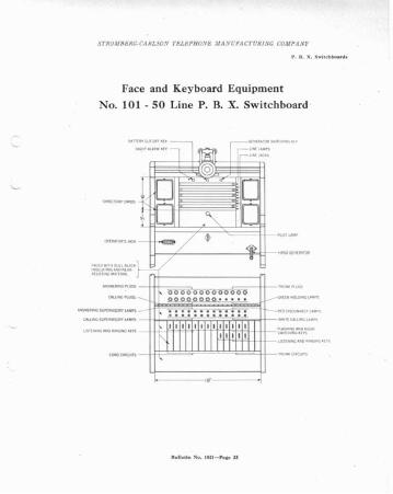
Face and Keyboard Equipment
No. 101 - 50 Line P. B. X. Switchboard
oo
CALLlNGSUPERVISORYLAMPS-jH+~~U~~::;=;~~r=f-1-
LISTENING AND RINGING KEYS-jH-ffF¥ffftTt~~F.4-I-H-~~i~~~~t~~V~'GH T
1"+-~12I--1--W- lIST EM NG AND RINGINGKEYS
1<-- - -19· - - ---1
Bu lle ti n No. IOll- Pa lle 23
STROM BERG·CA RL SON TEL EPHONE .IfANUFA CTUR fNG COMPANY
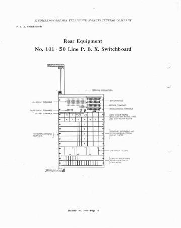
Rear Equipment
No. 101 - 50 Line P. B. X. Switchboard
Uu lletlu No . IOl l -J'a l1e 24
S TROM BE RG· CA RLS ON T EL EP II ON E M A N UFA CT UR I NG CO-lI PANY
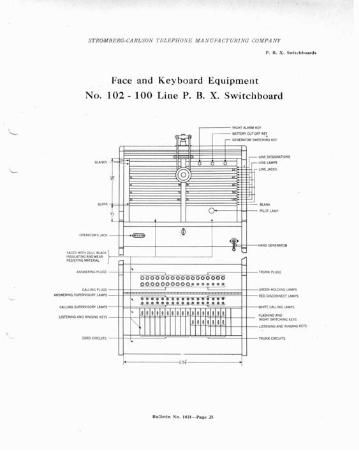
Face and Keyboard Equipment
No. 102 - 100 Line .P. B. X. Sw itch board
NIGHT SWITCHING KEYS
USTENING ANO RINGlNGK [ YS
~N"", "AR."rrm r--;= :~'::~~::T
-
1-
@
Jt- -<e> 1 $
I <£1 I I 0
J
000 0000000000 0 0 0 00 0 0 0 0 0 0 0 0 0888888 8
SI •• e • •••• • a e e • • "e." e eo" e e e " • ••• • ••
111111111 11 11111111111111111 111 11 11 I
~ 1 1 1 1 1 1 1 1 1 Ht}1~ :
FACEOWITHDULLBLACKIN$ULATING AND W[ARI'lEStSTING MAT[ RIAL
CALLINGPLUGS
ANSW[R ING SUPERVISQRY LAMPS
f--- - -----i2>f------.j
BII:Jc tln :-00. I 021-Pa~e 25
STROM BERG-CARLSON TEL EPllON E MA N UFA CT URI NG COMPANY
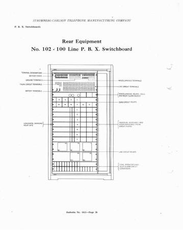
Rear Equipme nt
N o. 102 .: 100 Line P. B. X. Sw itch bo ard
TERMINALOESlGNATIONS
BATTERYFUSES ..·...-;~~=a~'SCE LtAN EOUS TERMINA
-
~J! mmlllllll!!H!IIIIIII- 1M ClRCUITTERMINALS
00 0 I I MISCELlAN[O USRE tA Y$lA ND NIGHTAtARhl BUZZE
1- 1 ' 1 'CORD CIRCUIT RELAYS
1<> 1' 1'
}- r~~~~:i~~~~~;~~~'
.
D D DL1N[ CIRCUITR ELAY$
D D'1111 1111111
{ ~~'.:';,~~~~ cmcun'111111111 i l l l l l
STR OMBERG·CA RLSON 7·ELEPHONE MA N UFA CTURING COM PA N Y
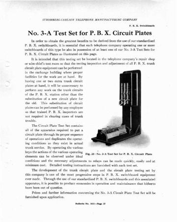
No. 3-A Test Set for P. B. X. Circuit PlatesIn ord er to ob ta in th e grea tes t benefi ts to be derived from the use o r our sta nda rd ized
P . B. X . switchboards . it is esse n tia l t hat each te leph one compa ny operating one or more
switchboa rds or t his type be also in possessi on or at least one or our No. 3-A T est Sets for
P . B. X . Circuit Plat es as illust rated on this pag e.
It is in tend ed t ha t th is test ing se t be loca ted in th e te lephone compa ny 's repair shop
or wire chief 's test room so t hat the testi ng inspe cti on a nd adj us t ment of a ll P . R. X . t runk
circuit plat e equ ipment can be perf orm ed
in th e exc ha nge building wh ere proper
facilit ies for the work a re a t han d . Byhavin g one or two extra tr unk circuit
plates a t han d , it will be unn ecessary to
pe rform a ny work on t he t runk circ ui ts
o r th e P . B. X. sta tio n othe r th an th e
subst itu t ion of a new circu it plat e for
th e old . Th is subs t it u t ion of circuit
pla tes ca n be perform ed by a ny employee
so th at trained P . B. X. inspect or s are
not req uired in clea ring cases of tr unktro uble.
T he C irc uit Pla te T est Set co nta ins
all or th e a ppa ra t us required to put a
circuit plate th roug h it s pro pe r seq uence
of ope ra tio ns an d d uplica tes the ope ra t
ing condi t ions 'a s th ey exis t in ac tua l
t runk serv ice. By ope ra t ing th e va rious
keys th e ac t ions of th e vari ous operat ing "·ia . 23- No , 3-A Tear Se t fo r P. B. X. Cir cui t Pl at eelem ents can be obse rved und er idea l
con dit ions an d th e necessar y ad jus tments to rela ys ca n be made q uickly. eas ily and a t
min imu m cos t. Detailed testing instruct ions a re furni shed with eac h test se t .
T he dev elopment or th e t run k circuit plat e a nd th e cir cuit plate tes t ing set by
thi s compa ny is one of t he most progressive steps in P . B. X . swit chboard eq uipme nt
ever mad e, T hrough th e use of our sta nda rd ized. P . B. X . switchboa rds a nd th is associa ted
a ppa ra tus, it is possible to pr odu ce econo mies in opera t ion and ma intainance t hat hith er tohave bee n out of ques t ion.
P rices a nd furthe r inform ati on co nce rn ing the No, J- A Cir cuit P lat e T est Set will befurni shed upon applica tion .
Bull _tin No. tOl l-Pae_ ]1
S TROM BERG-CA RLSON TELEPJIONE MANUFA CT URI NG COMPANY
p. B. X. ,Swit ch boa r d•
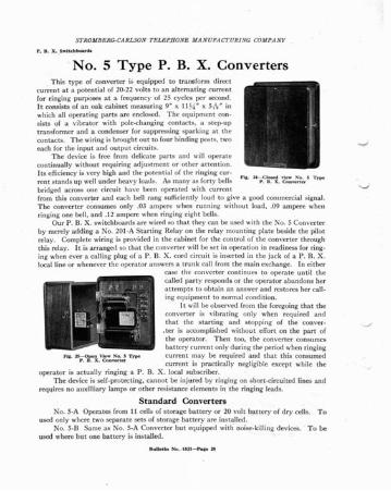
.No.5 Type P. B. X. ConvertersThi s ty pe of converte r is equipped to tr ansform di rect
curren t a t a pote nt ial of 20-22 volt s to a n alte rna ting cur rentfor ringing pu rpose s a t a frequ ency of 25 cycles per second.It consists of a n oak cabinet measuring 9" x 1134 It x 51
s• It inwhich all ope ra ting pa rts are encl osed . Th e eq uipmen t consists of a vibrator with pole-chang ing contac ts , a step- uptr an sform er a nd a conde nser for supp ressing spa rking at thecontacts. Th e wirin g is bro ught out to four bind ing post s, twoeac h for th e input a nd out put circuits.
Th e device is free from delica te pa rts and will oper a tecont inually without requ iring adj ust ment or othe r attention .Its efficiency is very high and the pote ntia l of the ringing current sta nds up well und er heavy loads. As man y as fort y bells Fill . 2~~. 1:::' 1'~~~ 5 Typo!'
bridged ac ross one circuit hav e been ope ra ted with curren tfrom this conve rte r a nd eac h bell ra ng sufficiently loud to give a good commercia l signal.T he converter consumes on ly .03 a mpe re when running- with out load , .09 a mpere whenringing one bell, a nd .12 ampe re when ringing eight bells.
Our P. B. X . switc hboa rds a re wired so t ha t t hey can be used with the No.5 Conv erterby merely add ing a No. 201-A St arting Relay on th e rela y mou ntin g plat e beside the pilotrelay. Comp lete wiring is pro vided in t he cabinet for th e control of th e converter throughth is rela y. It is a rranged so that the converter will be se t in opera tion in readiness for ringing when ever a calling plug of a P. B. X . cord ci rcuit is inserted in t he jack of a P . B. X .local line or wheneve r t he oper at or a nswers a trun k ca ll from the main excha nge. In eit her
case th e converter continues to operate until th ecalled part y responds or t he opera to r ab and ons herattempts to obta in an answer and res tores her ca lling eq uipme nt to normal condi t ion.
It will be obse rved from th e foregoing tha t th econ verte r is vibr at ing only when req uired a ndth at th e sta rti ng a nd stop ping of th e conver
. ter is acco mplished with out effort on th e pa rt ofth e operator. Then too, th e converte r consumesbatter y current only during the period when ringing
Fla.~~.V~~~i'; Type curren t may be required and th at t his consumedcurrent is pract icall y negligible except whil e th e
opera to r is ac t ually ringing a P . B. X _ local subsc riber.Th e device is self-p rotec ting, ca nno t be inju red by ringing on shor t-ci rcuited lines a nd
requires no auxillia ry lamps or other resist an ce elements in th e ringing lead s.
Standard Conve r te rsNo. 5-A Oper at es from I I cells of sto rage battery or 20 volt ba tt er y of dry cells. T o
used only where two sepa ra te sets of sto rage batter y a re installed.No. 5·B Sam e as No . 5-A Conv ert er but equipped wit h noise-kill ing deviees. T o be
used where but one battery is installed .
S TRO M BERG· CAR LSON TE LE PHONE MA N UFA CT URI NG COM PANY
Operation of CircuitsTh e following is a co mplete narr a ti ve of th e functions and oper at ions of th e c ircuits of sta ndardized
P. B. X . Switchboards. Th e subj ect s a re div ided for convenience as follows:
I- LocaI 'P. B. X. Call,.2-Trunk Call s, Outgoing fro m P. B. X. Switch board.3-Trunk Call s, In coming to P. B. X . Swit ch board....- Direct Line Night Service ove r trunk.
i-Local P . B. X . Ca lls:(a) P . B . X . S ..bscriber Calls :
Wh en a P. B. X . part y des ires a not her P. B. X . par ty t he ca ll is mad e in the usual wa y by removing t hetelephon e receiver (rom th e hooksw itch , th ereby lighting th e line la mp id t he P . B. X . switc hboa rd .
(b) P . B . X . Operator An swers Call:T he act of plugging into the co rrespo nd ing P . B. X . line jack, loca ted d irec tl y un der th e lighted line la mp,
with the answeri ng (bac k) plug or a P . B. X . co rd circuit , cuts off t he line signa llmg apparat us in th e jac k andexte nds th e talk ing circu it to t he P. B. X . cord ci rcuit. Th e opera tor listen s by t hr owing t he combined list en~~fkinngd~~F~~e:t~Y hand le or t he P . B. X . circuit toward s t he plugs (locking pos it ion ) 50 as to connect he r
(c) Ringing the Called P . B . X. S ..bscriber:If a nothe r P. B. X . pa rty is des ired t hen th e ca lling plug (fron t } or th e P. B. X . cord circ uit is inserted
into t he jac k or th e desi red P . B. X . line. Th is light s th e ca lling (fron t ) superviso ry lamp or the P. B. X .co rd circ uit .
T hr owing the combi ned listenin g and ringing key han dle t oward s th e operator (non-locking positi on )rin gs th e desi red pa rty .
(d) Rin ging with Power Generator:\ Vhen power gener at or curre nt is ava ilable, th en th e genera to r switching key marked " G E N" shou ld be
depressed so th at th is current will he co nnec ted 10 the ringing key common wires. Thi s a llows th e ringing tobe done by t he simp le mov eme nt or th e ring ing key a nd wit hou t a ny other manual operatio ns on t he pa rt ort he operator.
(e) Ringing with Hand Generator:I£ th e power generator curre nt is not ava ilabl e th en t he genera to r switc hing key. marked "GEN" should
have it s plun ger in th e "o ut " posi tio n, so t ha t t he rin g in~ cu rre nt prov ided by turnmg the cra nk or the handgenera tor will be co nnec ted to t he ringing key comm on wires .
(j) Two P . B . X . Parties Connected for Talking:
te lepr~:e:~=i~~eo~hinca~~:n':j ~~;~; I~~~h~r~h:~~'h~r~~~~~i:u[~~ ~ee~~k:i~~:. ca~~t::~u~te~~i~~~i':h~leted an~in t he ta lking condition, a ll signa l lam ps assoc ia ted with this part icufar conn ect ion
(g) P . B . X . Parti es Disconnect:When bot h P. B. X . parties hang up th e receiver !'!at t he telephones, th e corresponding tw o superv isory
lam ps in th e co nnect ing P . B. X . cord c ircuit will ligh t . T his notifi es th e operator t hat th e conversa tion IScomplete d and that t he co rd c ircuit used ca n be pu lled down .
(h) P . B. X . Party Recalls:I£ either P . B. X . pa rty desires immedi a te a tte ntion or th e oper a to r when a co nve rsa ti on is complet ed,
~~~dmci;~~r~ort~ish::h:'~~~t~~~ds1:~i r~~~~e:i~~:t:r tl~e {i~tr;:f:~~i~fes~~d~~~i~afuii~ri~:rP~r~~~:(i ) Common Pil ot and Night Aklrm :
to a ;:~~~~ l~iJ:I:~~~~~~it~\\:hii~t iiStr;·~:;'d;el~~.r:1 C:.:~i~.h~:~~~do~~ ~~ ~~::~(~~rd~~~~~edecl~~or supervi sory lamps a re light ed .
A common night a la rm buz zer is also provided in t his swit chboard a nd so wired as to operate when the
f~II~~~:~a~ufl~sO~r). P\v;;~~ntghi~hk~yt~: r~if~~:~~~~~:tll~h~rngg ~'it~)kt~e '~~~; 'ail~:~ ii~sdi~~~~:t:s;~~o~th e pilot relay c ircu it.
STROMB ERG. CARLS ON TELE PHONE MA N UFA CT URI NG COMP ANY
2-Trunk Calls, Outgoing from P. B. X. Switchboard:Th e trunk circuit used with th is standard ized P. B. X. Switch boar d is designed to be connected to any
~~r~ thUe~~t:~: tl~:eC~f~i~e~~~:: t~I~~~ln~~ce. 80 that t he centra l office ans wering a nd ca lling funct ions
(a) Ordering of Central Connection by P . B . X . Party:
circu~~~d tned~i~a:t~h:~B~oX~:~~rsd:sli::lac~~li:r?ii:e.Pih~~~~i:~s~~rine:~iu~:r ~h~~\::~'C:;l~;i::i~is removed from t he P. B. X. line jac k and th e plu g oranon-bu sy t ru nk line inserted in it s place. This allows
~~: ~~';:;af~lfic~t~;;r~~~'r i~Yt~:s~~~:~~~Ir::~~ee~f~~:b~~~~t~~~:~Ib~s~~~i~g ~h;tef:;~~~: h::~~switch up a nd down, a nd with out d istu rbin g th e P. B. X . ope ra to r,
mea~h:r~'~ ':·X.~~:t~i~~itt r~hC:rui~~nn~ht~:~h'aI~ r~~sk'~lu~~ ~~:~ ~·~J·a~~I~· ~l~~a n:i~~f~~l t~~cent ra l office. T his instr uction is gwen on a designati on plat e, locat ed at th e right han d side or the key she1f.
(b) Ordering of Central Connection by P. B . X . Operator:If t he P. B. X. pa rty desi res t hat t he P. B. X . ope rat or do the ca lling of the centra l office subsc ribe r, th en
th e P. B. X. ope ra to r thr ows t he combi ned listenin g and ringing key lever of a non-busy t runk into th e list ening position, which is towa rds th e plugs (locking). It is not necessary t hat the correspon ding t runk plu g beinserted in th e jack of th e P. B. X. line un til t he P. B. X. opera to r knows wheth er th e des ired cent ra l office -.......Jsubscriber ca n be reached .
the ~~eoii~~tili~h~~ t;~: tli~~kl~~t~~~~h~e~e~~i~ffi~~ld~~eeip~~~ ~.~ I~~~~ ai:~:St ~~ed~ir~ l~~~abe~ ~~. ~~dc~n:~~~:dt~~ h~tdift~~el~~le:n~r:h:ep:ad>t .t~~t~isli=t~~OI~~~tt~tt!~~·~~t~t:h?:S~~ti:ia~ ·trunk line is insert ed in t he line jack of t he P. B. X. pa rty who originated th e ca ll, and t he P. B. X. line rungin t he usual way by th rowing t he combined listen ing a nd ringing key of th e t runk circu it to wa rds th e operator(non-locking posit ion).
(c) Holding of Trun k Indicated by Green Lamp :
until;~~ ~~B~ ~~I~~y~:P '~~:.en~~i~~~~;h~~~ea~r~n~~~~~~ir:d~i~snfi:h~tt~h~"~~u~kdi~er::i~~s~~f~t~the opera tor as it light s a nr;.ema ins light ed only as long as th e holding circuit is connected across a tru nkline. Thi s green la mp is used for no ot her pu rpo se, so as to avoid confusion of signa ls.
(d) Trunk lI o/ding Connection Cannot be A ccidently Released:
loek~~;i~~~ ~~rd~~~ld~f~~C~~~~ght:~~r~ :r"~I ~;ea~dj~~k":.~ ;}lrl~~~~e~o~~~n:;t~i~ ~y~~~~~new safeguards wh ich ma ke thi s t runk pra cti cally fool. proof.
(e) Trunk Disconnect: .When t he P. B. X . pa rty is t hrough talkin g and han gs up the telephone receive r, t he cent ra l office dis-
p~nB~X .s~~i~~~~d:ed~i~~~r~k~~:~aj l~ffi~ed~S;r~~~to~r~'~ ~i~~a~~r~~:rt:~np~ttd~~~kth~~~~n~t~~~first , wit hout ca using an y difference in th e di sconn ect fun ct ions of th e P. B. X. or cent ra l office switc hboa rd .
(J) Trunk Disconnect Pilot and Ni ght Alarm Circuits :Th e red disconn ect lamp in the P. B. X. t runk circuit is connected to th e common pilot circuit and night
bell circuit th e same as (or th e local line lam ps a nd local cord circuit a nswering supe rviso ry la mp.
(g) Trunk Cleared of Useless Bridged Apparatus During Talkin g:Th is tru nk circui t is so designed that when t he P. B. X. bat tery is connected for talk ing the trunk
ca lling relay and holding coil (if the trun k is arranged for holdin g coil) are remo ved from across the circuitso as to a void high freq uency tran smission losses .
(h) Trunk I nstantly Available fo," Incoming Calls from Centralwhen P . B . X . Party /langs Up :Th e instant th e P. B. X . pa rty han gs up, after a conversa t ion, th e t run k line calli ng signal circ uit is re
esta blished at the P. B. X. switc hboa rd so t hat t he centra l office ca n call-in on a t run k. even be fore t he P. B. X.ope ra tor has pull ed down th e tr unk conn ection . Thus it is possible to have a ca lling (white) lamp a nd a disconnect la mp (red) light on a trunk a t one time. Th is cond ition is not confusing as th e P. B. X. operator
:Oth~ ~~~~hlin~~lrl;ai';tc:~~n:~:; ~f~i~i~~~~~~i::aP~~ed~~~r ~~ethi:~~~~~nlif:d~:t~nSt~~th e P. B. X. pa rty is thr ough talking a nd has hun g up. In such a case th e P. B. X. opera to r will pull down th etrunk plug an d a nswer th e t runk line t he sa me as for an y incoming t ru nk call, subseq uently descri bed .
BuDetin So. IUI-Palle 30
STROMBERG· CA RLSON TE LEPHONE MANUFA CT URING COMPA NY
(i) Trunk Flashing K ey :If (or any reaso n the P. B. X . operator ,~..ishes to flash th e superv isory lamp a t th e cent ral office, when a
;~i~~h~;g~~Yh~ndiet~:w~rd~e:=~~o~~t~~i(~:.t:k~~~~iti~~f.IY+t~~;~:~h~~~ik~r:~i~h~~~:nngda~i~~~~~r~t~ne~~}nt~~: k:;h~;:~n~i~~ ~~~~~ ~}~h~~ ~~~fin~~d~~:i~~o(~he~~~tcl~~i~f~~~h:~B~i}t.~;i:::~~~i~~: ~~~~~~~o~ffi(~~urh~~~~~a:afcewi~~~at::,hed, wh ich is th e cu stomary ind icati on for a reca ll
T he P. B. X. t runk listening key hand le ca n be thrown to listenin g position when " flashing back" so th a tth e P. B. X . operat or' s telephone set will be on the circuit in read iness and the P. B. X. operato r ca n respondimmed iatel y when th e central oper at or comes in on th e circu it .
Thi s flash circu it is so arr anged as to do away with disagreeab le clicks which would ot herw ise be intro duced in th e connected P. B. X. subscriber 's te lephone as well as in the operator' s head te lephone, when workin gthis key .
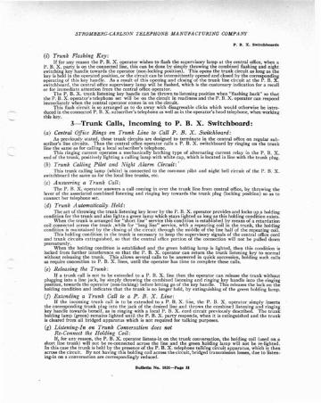
3- Tr u n k Calls, Incoming to P. B. X . Switchboard:(a) Central Office Rings on Trunk Lin e to Call P . B . X . SwiUhboard:
As previously sta ted , t hese trunk circui ts a re designed to termin ate in th e cent ral office on regular sub.scriber's line circui ts. Thus the centra l office operat or calls a P. B. X. switchboa rd by ringing on the trunkline th e same as (or calling a local subscriber's telephone.
Thi s ringing current opera tes a mecha nically lat ch ing ty pe of alternating current relay in the P. B. X.end of th e tru nk, positively light ing a calling lam p with white ca p, which is located in line with th e trunk plug.
(b) Trunk Calling Pilo t and Night A larm Circuit :'T his t ru nk ca lling la mp (white) is connected to th e common pilot and night bell circuit of the P. B. X.
switchboard the same as (or the local line t runks, etc.
(C) A nsuiering a Trunk Call:Th e P. B. X. ope rato r a nswers a ca ll coming in over the trunk line (rom cent ral office, by throw ing the
lever of the associa ted combined listening a nd ringing key towards th e t runk plug (locking posit ion) so as toconn ect her telephon e set.
(d) T runk Automatically . Held :
cond~~oena~r~~~h[~u~ik~~~ea~~li~~its: ~n~~:e~era~~e~~i~~~~a~~ n~~~~rj~~~ ~~ot~~eh:ld1n~dfti~nh~~1~~:'When the trunk is arra nged (or " short line" serv ice this condition is esta blished by means of a retar da t ion
coil connected across t he trunk ,while (or " Ion~ line" service , wit h a repeating coil in the t run k, the holdingcondit ion is maint ain ed by the closing of th e Circuit through th e middle of th e line half of th e repeating coil.
Th is holding cond it ion in th e trunk is necessary to keep th e supervisory signa ls of th e centra l office cordand tru nk circuits ext inguished , so th at th e cent ral office port ion of the connection will not be pulled downprematurely.
\Vhen th e holdin g condit ion is estab lished and th e green holding la mp is lighted , th en th is cond ition islocked (rom furth er int erference so that the P. B. X. operat or ca n return the trunk list en ing key to normalwith out releasing the t runk . Th is a llows severa l calls to be answered in Quick succession, holding such callsas requ ire connection to P. B. X . lines, unti l th e opera tor has t ime to comp lete th ese calls.
(e) Releasing the Trunk :If a trunk ca ll is not to be exte nded to a P. B. X. line th en th e opera tor ca n release th e t runk with out
pluftfo"n~ ~~~a~~~h~~c~r~~:i<:~:r.I~ki~)tet(~~eie~~~~~I~:~hi:{e~n~a~d~~g;hrs :d~::si~~~ :~ekr~~~h~Ciding conditio n and indica tes th at th e trun k is no longer held, by extingu ishing of th e gree n holding lam p.
(f) Extending a Trunk Call to a P. B . X . Lin e: .If th e incomi ng trun k call is to be extended to a P. B. X. line. th e P. B. X. operat or simply inserts
~~~ ~a~di~t~~:~d~rh~:J}~~~i~or!~:i~~c~~h t:j~ii~ ~i.nX~~r~h~ir~~i~h;r~:~~r:~::tri~ aTi:i~r~~~holding lamp (green) remains lighted un ti l t he P. B. X. party responds, when it is ext inguished and th e t runkis cleared (rom all bridged appa ratu s which is not required (or talking purposes .
(g) Listening-In on Trunk Conversation does notRe-Connect the Holding Coil:If , (or any reason, th e P. B. X. oper ato r listens-in on t he t runk conversat ion, t he holdin g coil (used on.a
ahort line t runk ) will not be re-connected across th e line and the green hold ing la mp will not be re-light ed .In this case the trunk is held by the presence of th e P. B. X. telephone ta lking circuit apparatus, which is t henacross the circu it . By not having this holding coil across the circu it , bridged tra nsmission losses, due to listening-in on a conversati on are corr espondingly reduced.
BuUetill No. IIU-PaIl. 31
S TROMBERG-CA RLSO N TEL EPHONE MA N UFA CT UR I NG COMPANY
(h) P. B. X . Party ca1l Flash P _ B. X . Operator if Trun k Li stenin gK ey is A ccidently Lef t [ 11 It s Operated Posit ion :
key;~~:s~~::~~~itio~f (~~bl:~h:~~~ei~;::t::¥sn~a:r:':I:;ho~C::~~~~lnle:.;~n~i"rn~~ett:~~\~i:t:r~~fcircuit . T he han~in g up of t he receiver at t he connected P. B.X. telephone will cause tb e holding lamp (green)
~lo~l~euap~~d%~~h;i ll Jah: ;: ~~!~:r:;;n~~;p:r~~§h~~dt~~:;a~~~:~r:~~~h~~r;:~~;?:~~:n~ro~hf~r~:=~~~~serv ice.
ism ~hth~r~nl~~X~ ~s~~~hn~d:~rc~o i~n~~~; ~~h~~~toT~~~t:~; ~i~ht~~~ ~i~~i:h~~~~~~~ed:;:~d;t he P. B. X. opera to r's immed iate a tt ent ion.
4-Direct Lin e Nigh t Service Over Trunk:
:~~~~t~~;iii~J~;~~~:~3i~:;~;~;~~:~ft~~f;~~L~2~':::::;:;I ::~~~u~;::::f:I~~e~~h~t;~~\~~~~e~~-ot: :~vi~ ;~~~~~ d:c~!~i~~:;~h: ;o~i~~~~~gh:~i~g~~,~.hat is necessa ry
When th e P. B. X . IS arra nged ror " Iong line" t runk service with a repeating coil to feed talking a nd signaling batt ery from the P. H. X. switchboa rd to th e P. B. X. subscriber (through a No. 2- A Circu it Pla te), th en
r~gf~'~~8~cinc:.~nch~~·~~:h~:dt b~t\\~i~~ ~~; i~df~:n~~h~h~:I~i~~~~~:r~l~~ ~~~~~a~~~~S:fi~~~~n~e~e?~
(a) N ight Swit chi1lg K ey Clears Trunk Circuitf rom all S eries ami B ridged Apparatus:
orde;: nt~~~~w:bi~ i~~i~~~i~:ke~h~~I~oist~~ ' ; ~~n~~:~i~ltru~~~nt,h:h:~~kgi~~~Z~i~:t(~;i.~:yo~~~~!with the signaling a ppara tus in circuit. With the handl e or:his key thrown towa rds the trunk plug, then th etrunk is connected through direct (for night service) without any bridged or series appa ra tus or coils in th ecircuit .towa;Jt:St h:I~~~:ro;~":hi~h i~0:~I~ki~i;~~it1~~ribed for flashing purpo ses" by throwing th e lever handl e
Th e plugging up of one of th ese sta ndard t ru nks into any P. B. X . line, with th e switching key set for
~~:~L~;~'~~~afi~ffic~h:u~;i~~,~t~~na~':{ t~~:~h:~~i~~il:h ~h:~~~t::~~~i;io~el~~~di~io~~s~~~iC::~ :~Jo:o"service.
(b) Ni ght S ervice A ssured EVe1l IVhm the Ni ght K ey is Not Th roum :Thi s sta nda rd ized P. B. X . switchboard is provided with the usual battery cut-off switch , so th at all
current for opera ting the P. B. X . lamps and relay s, with the exception of the superv isory relays, can be d isconnected when th e opera tor leav es the switchboa rd at night .
Thi s battery cut -off switch is a No. 119 Key, with top sta mped "BAT" , wired so as to connect batt ery.when plunger is pulled out and disconn ect battery when plunger is locked " in" .
Th e reta ining of battery current for th ese superv isory relays in th e repeat ing coil tr unk, ma kes it possible to signal the cent ra l office from the connected P. B. X . telephone whether th e night switch ing key is in its
~::d~s~~o:~;r~~~'cyTp~:~'~~h:~~er:ii~h,~a;~t::nagu~Un~~h:e~~ci~ l~.i::l~re usually employed for night
Operation of Trunks From Magneto Main ExchangeWhell these standa rd ized P. B. X . switchboards are equipped with ring-back keys in the t runks for use in
connect ion with a magneto cent ral office, th ese t runks will opera te as follows :(a) Trunk Calls f rom M agneto Central :
Calls from a magneto cent ral office light th e whit e ca lling la mp in the P. B. X. trunk, the same as
~~~r~:klis~e~~~tk~~.,~?hi~~·isi~li~e ~~h !)iig~t~' t~~ka:::;';~:=rd~hth: t~~~k :l~g~hTh1::c~he~~~~~::h~~t he white ca lling la mp a nd light s th e green holding lam p. T he green lamp remains lighted to remind theoperator tha t she has a cent ral office ca ll, un til the t ru nk is released, either by the operat or th rowing the listen.ing key in the op posite d irect ion or by th e extending of the ca ll as described in the next para grap h.
(b) Ext endin g a Trunk Call from Ma gneto Central:
plUK~~:~~~:~~~n~ ~~ ~s~~~ p~~~~~t~~~~d ~~~.~:I:~;oo~i~Kt~h: ~~~~~ ~f~h~~rc:~~r I~~::~~~:hke~u~~wards herself. When th e P. H. X. party respond s the green lamp will be extinguished, showing th e P. B. X .operator that th e cent ral o ffice trun k cal l has been disposed of.
Rul ltorln .X o . IOU - Pa • • 31
STROMBERG-CARLSON TE LE PIlONE .IlANUFACTURlSG COMP ANI'
(c) Disconnecting Magneto Tr unk :
liRht~~:h~:di~~~:~t~~~:' fhi:~~a,:~pu~~~ fle;ts~:drc;r~h:~~~il ~~he:J~~:nx.w~~~h~o~ki~~ ~h;~a:~!switc h of th e te leph on e up a nd dow n in t he custo ma ry ma nn er for such re-ca lls.
Th e P. n.X . opera to r finish es t he di sconn ect ion by pulling down the t r unk plug and th en rin ging o ff t hece ntra l office by th rowin g toward s her self th e han dle of the key locat ed next to th e trunk plug .
(<I) Trunk Calls to .lfagneto Central:Ca lls fro m a P. B. X . party which a re intended for the magneto central office are exte nded by th e
P. B. X . operator removin g t he loca l cord circu it plug , used in ans werin g the ca ll, and substituting a tr unk
~ted~:r;:t ~~ ~~ ~~~kt~ru~~~~~ ~~~ir~:t~ni~~i~ra:oo~c;;i~ ~~r:~~~~fonh~~1~ec::tol~~r:e:~magnet o switc hboa rd s.
Operation of Trunks From Au tom a t ic. Main Exchange:When th ese sta nda rdized P. B. X . switchboards arc equipped with dia l keys in the tr unk circuits a nd with
auto mat ic dia ls, t hen th e oper a tion of th e trunks will be as follows:(a) TTI/nk Calls from Automa tic Central:
Calls from the cent ra l office to a P. B. X. party are handl ed exactly as from Centra l Ener gy main excha ngesas described on page 31 of thi s bulletin .
(b) Disconnecting the A utomatic Trunks :Th e d isconnec ting of t hese tr unk ca lls is mad e di rect to the ce ntra l office when t he P. B. X . pa rty ha ngs
up, leaving t he tru nk in read iness for immed iate inco ming ca lls, eve n before t he P . B. X . operato r has pu lleddown th e co nnec tion, as described in paragraph "h".oo page 30.
Th e red t ru nk la mp light s for this d isconnect ion at t he P. B. X . switchboa rd a nd ca n be flas hed for a re-callin t he usual ma nner by workin g the tel eph one hook up a nd do wn .
(C) Trunk Calls to A utomatic Central:Call s from th e P. B. X. te lephones to the automa t ic office are made by the P. B. X . ope rato r as follows:
t"on n~~s:h:~ia~i~~ ~h~t~~~~t ~~d ~~nt(~I: ~Z ~i~~e:t~bl~:h:s\h~u~~I~i~:r~~nn~~~~~~c~~:s~~:~~~~kci~~u\~as described in par agrap hs " b" and "c" on page 30 of th is bullet in.
Second, the opera tor dia ls the number wanted in the auto ma tic centra l office by working the d ial in theregular way.
and ~~ea~~~~~uC;;t~lh;ith:;t:h~lp~ KUx~ ~~h:..at~~ :~~:~h:~~t:~~~:n~a~~t~:t~~~iiSth:i~~~~ki~ ::~nr:c~~to a P. B. X. line and a nswered hya P. B. X. par ty . T he releasing by hand is descr ibed in para grap h "e" onpa ge 31.
(d) Trunk Au tomatically Held After Dialing:After the P. B. X. operator dial s the numbe r wa nt ed in the automatic cen tral office, the n th e circuit is held
by th e hold ing conditio n just described, even a fter the tru nk dial switching key is restored an d unt il the callhas been ans wered by t he r . B. X. line or released hy th e P. B. X. oper ator as descri bed in paragra ph "e" onpage 31.
(e) Tr unk Night Service to Automatic Central :Night servi ce from some of th e P. B. X . telephones to th e a utomati c centra l office ca n be provid ed
as described on page 17 of th is bulletin by furn ishing th e parti cu lar P. B. X. te lephon es with dials, and in th e
h~S:dl: ~~i, ~:\~:r~~~h~ :;~~k ~f~~tiT~ec~~.t1~ ~i~~~k~I~~~07;~ ~~~ntg:i~~i;t~i;IRal~:~ ilie t~i~li~i .
~~~I~h~ot~~:wc:~~~~~~~e~~t;tO~~eu:~fd~~~lift~~ti~~t~~ila~~~~ t~~ p~IB~X~':i~~hr:~dauriu~~~es:i~~t .(j) Special Advanta ges of A utomatic Trunk :
Th e adva ntages descri bed in para gra phs uti" , "e" and " II" on p3$e 30, and "c' and " h" on pages 31and 32 apply also for th is stan dardized tru nk when used in connect ion With an a uto matic centra l office.
Rull e d n So. IO'I-Pa l e 3J


![[B1] STROMBERG Jonas_Role of Alternative Fuels](https://img.pdfslide.us/doc/110x75/577ce47b1a28abf1038e73c5/b1-stromberg-jonasrole-of-alternative-fuels.jpg)