Embed Size (px)
Citation preview
Stretch Efficiency for Combustion Engines: Exploiting New Combustion Regimes
C. Stuart Daw, Josh A. Pihl, V. Kalyana Chakravarthy, James P. Szybist,
James C. Conklin, Ronald L. Graves (PI)
Oak Ridge National Laboratory
2010 DOE OVT Peer Review
June 7-11, 2010
This presentation does not contain any proprietary, confidential, or otherwise restricted information
Gurpreet Singh and Ken HowdenVehicle Technologies Program
U.S. Department of Energy
Project ID: ace015
2 Managed by UT-Battellefor the U.S. Department of Energy
Overview• Timeline
– Start• FY05
– Finish• Ongoing
• Budget– FY09 Funding
• $250K– FY10 Funding
• $250K
• Barriers– Max energy efficiencies of existing
IC engines (including HECC and HCCI modes) are well below theoretical potential
– Overcoming these limits involves complex optimization of materials, controls, and thermodynamics
• Partners– Gas Technology Institute
• Partnered with catalyst supplier, engine OEM
– Universities• Texas A&M University • University of Wisconsin • Illinois Institute of Technology• University of Alabama• University of Michigan, Dearborn
3 Managed by UT-Battellefor the U.S. Department of Energy
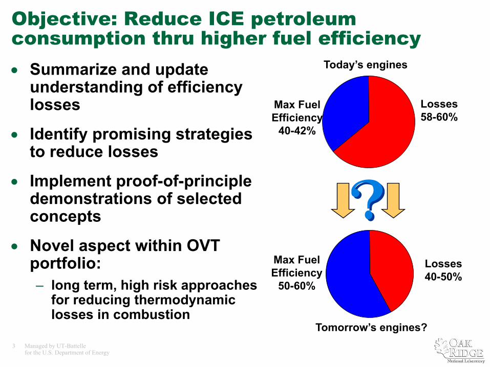
Objective: Reduce ICE petroleum consumption thru higher fuel efficiency• Summarize and update
understanding of efficiency losses
• Identify promising strategies to reduce losses
• Implement proof-of-principle demonstrations of selected concepts
• Novel aspect within OVT portfolio: – long term, high risk approaches
for reducing thermodynamic losses in combustion
Max FuelEfficiency
40-42%
Losses58-60%
Max FuelEfficiency
50-60%
Losses40-50%
Today’s engines
Tomorrow’s engines?
4 Managed by UT-Battellefor the U.S. Department of Energy
Milestones• FY09 Milestone (completed):
– Journal paper on preheating and thermochemical recuperation (CPER/TCR) as a means for increasing combustion engine efficiency (published in Energy and Fuels)
• FY10 Milestone (on track for completion)– Journal paper on chemical looping
combustion (an alternative approach to chemical exhaust heat recuperation) as a means for increasing combustion engine efficiency (September 30, 2010)
5 Managed by UT-Battellefor the U.S. Department of Energy
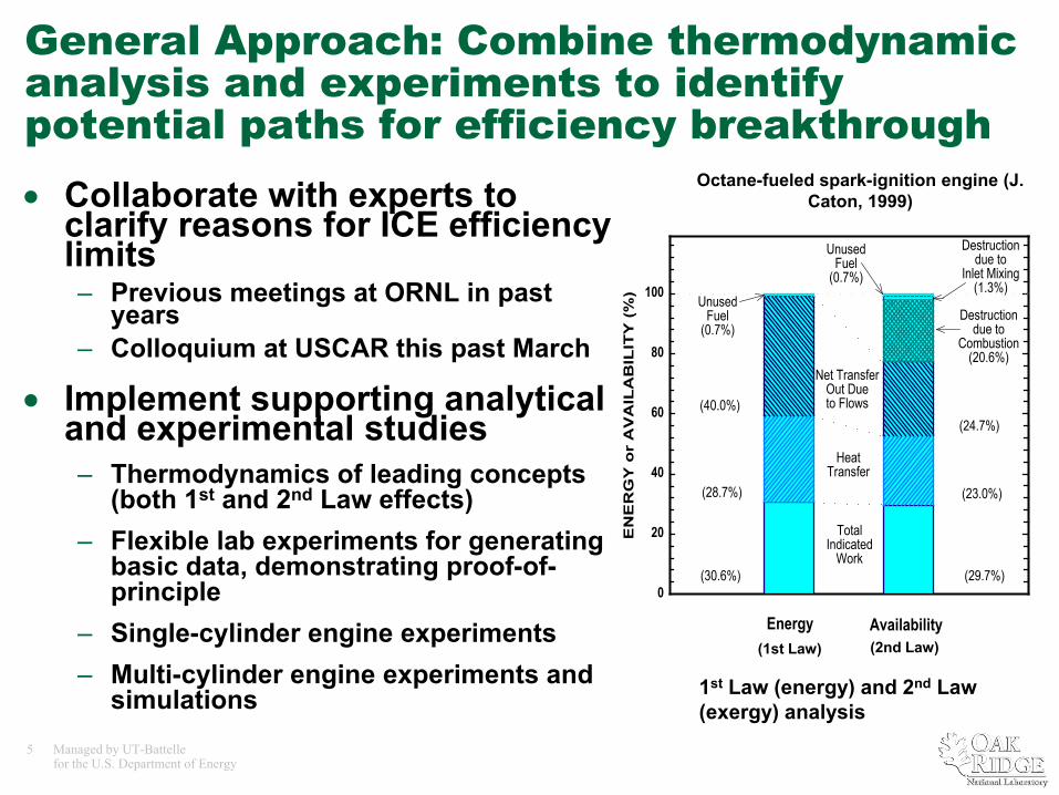
General Approach: Combine thermodynamic analysis and experiments to identify potential paths for efficiency breakthrough • Collaborate with experts to
clarify reasons for ICE efficiency limits – Previous meetings at ORNL in past
years– Colloquium at USCAR this past March
• Implement supporting analytical and experimental studies – Thermodynamics of leading concepts
(both 1st and 2nd Law effects)– Flexible lab experiments for generating
basic data, demonstrating proof-of-principle
– Single-cylinder engine experiments– Multi-cylinder engine experiments and
simulations
1 2E
NE
RG
Y o
r A
VA
ILA
BIL
ITY
(%
)
0
20
40
60
80
100
(30.6%)
(28.7%)
(40.0%)
Destructiondue to
Combustion(20.6%)
Energy Availability
UnusedFuel
(0.7%)
(24.7%)
(23.0%)
(29.7%)
UnusedFuel
(0.7%)
Destructiondue to
Inlet Mixing(1.3%)
TotalIndicated
Work
HeatTransfer
Net TransferOut Dueto Flows
Octane-fueled spark-ignition engine (J. Caton, 1999)
(1st Law) (2nd Law)
1st Law (energy) and 2nd Law (exergy) analysis
6 Managed by UT-Battellefor the U.S. Department of Energy
The engine efficiency colloquium held at USCAR this March has been helpful in focusing our perspectiveParticipants were:
•Paul Najit (GM)
•Walt Weissman (Exxon)
•Eric Curtis (Ford)
•Gary Hunter (AVL)
•Jerry Caton (Texas A&M)
•Noam Lior (U Penn)
•Tony Greszler (Volvo)
•John Clarke (Cat® retired)
•Ron Graves (ORNL)
•Robert Wagner (ORNL)
•Bengt Johansson (Lund)
•Dan Flowers (LLNL)
•Kellen Schefter (DOE)
•Terry Alger (SwRI®)
•Ron Reese (Chrysler)
•Don Stanton (Cummins)
•George Muntean (Cummins)
•Gurpreet Singh (DOE)
•Chris Edwards (Stanford)
•James Yi (Ford)
•Dave Foster (U Wisconsin)
•Steve Ciatti (ANL)
•Harry Husted (Delphi)
•Stuart Daw (ORNL)
•Pete Schihl (U.S. Army)
•Paul Miles (SNL)
•Roy Primus (GE)
•John Kirwan (Delphi)
•Tim Coatesworth (Chrysler)
7 Managed by UT-Battellefor the U.S. Department of Energy
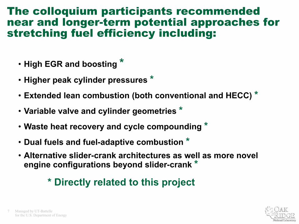
The colloquium participants recommended near and longer-term potential approaches for stretching fuel efficiency including:
• High EGR and boosting * • Higher peak cylinder pressures *• Extended lean combustion (both conventional and HECC) *• Variable valve and cylinder geometries *• Waste heat recovery and cycle compounding *• Dual fuels and fuel-adaptive combustion *• Alternative slider-crank architectures as well as more novel
engine configurations beyond slider-crank *
* Directly related to this project
8 Managed by UT-Battellefor the U.S. Department of Energy
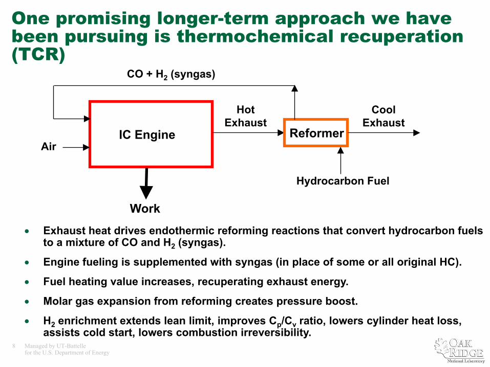
One promising longer-term approach we have been pursuing is thermochemical recuperation (TCR)
• Exhaust heat drives endothermic reforming reactions that convert hydrocarbon fuels to a mixture of CO and H2 (syngas).
• Engine fueling is supplemented with syngas (in place of some or all original HC).
• Fuel heating value increases, recuperating exhaust energy.
• Molar gas expansion from reforming creates pressure boost.
• H2 enrichment extends lean limit, improves Cp/Cv ratio, lowers cylinder heat loss, assists cold start, lowers combustion irreversibility.
IC Engine
Work
ReformerAir
Hot Exhaust
Cool Exhaust
Hydrocarbon Fuel
CO + H2 (syngas)
9 Managed by UT-Battellefor the U.S. Department of Energy
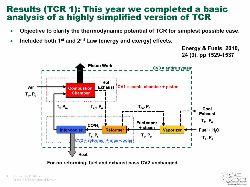
Results (TCR 1): This year we completed a basic analysis of a highly simplified version of TCR• Objective to clarify the thermodynamic potential of TCR for simplest possible case.
• Included both 1st and 2nd Law (energy and exergy) effects.
For no reforming, fuel and exhaust pass CV2 unchanged
CV0 = entire system
CV1 = comb. chamber + piston
CV2 = reformer + inter-cooler
Fuel vapor+ steamCO/H2
Air
Cool Exhaust
To, Po
To, Po
Tec, Po
Piston Work
Heat
Hot Exhaust
Teh, PoTv, Prc
Tr, Pr
Tef, Po
Fuel + H2OTv, Po
Reformer VaporizerInter-cooler
Combustion Chamber
Fuel vapor+ steamCO/H2
Air
Cool Exhaust
To, Po
To, Po
Tec, Po
Piston Work
Heat
Hot Exhaust
Teh, PoTv, Prc
Tr, Pr
Tef, Po
Fuel + H2OTv, Po
Reformer VaporizerInter-cooler
Combustion Chamber
Energy & Fuels, 2010, 24 (3), pp 1529-1537
10 Managed by UT-Battellefor the U.S. Department of Energy
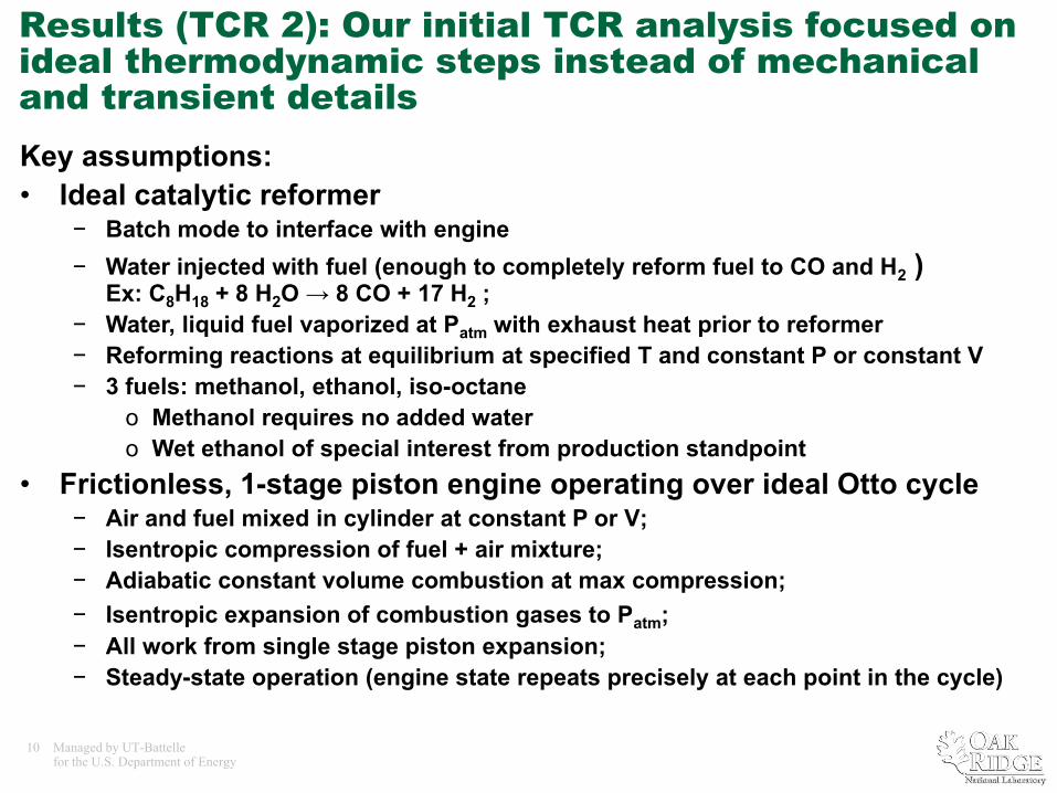
Key assumptions:• Ideal catalytic reformer
− Batch mode to interface with engine− Water injected with fuel (enough to completely reform fuel to CO and H2 )
Ex: C8H18 + 8 H2O → 8 CO + 17 H2 ; − Water, liquid fuel vaporized at Patm with exhaust heat prior to reformer− Reforming reactions at equilibrium at specified T and constant P or constant V − 3 fuels: methanol, ethanol, iso-octane
o Methanol requires no added watero Wet ethanol of special interest from production standpoint
• Frictionless, 1-stage piston engine operating over ideal Otto cycle− Air and fuel mixed in cylinder at constant P or V;− Isentropic compression of fuel + air mixture;− Adiabatic constant volume combustion at max compression;− Isentropic expansion of combustion gases to Patm;− All work from single stage piston expansion; − Steady-state operation (engine state repeats precisely at each point in the cycle)
Results (TCR 2): Our initial TCR analysis focused on ideal thermodynamic steps instead of mechanical and transient details
11 Managed by UT-Battellefor the U.S. Department of Energy
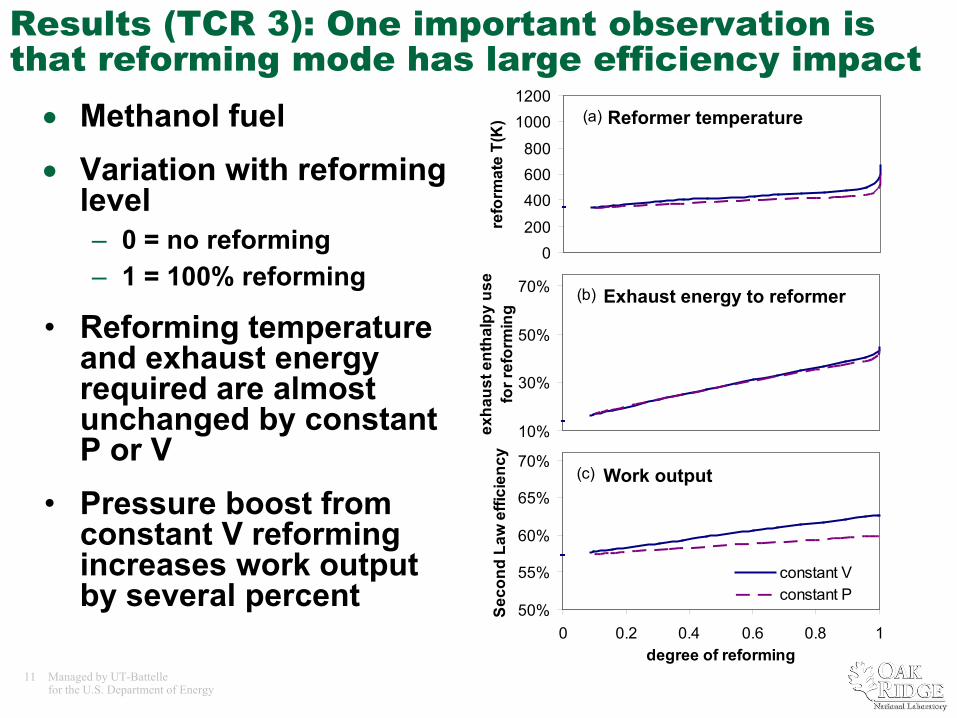
Results (TCR 3): One important observation is that reforming mode has large efficiency impact• Methanol fuel• Variation with reforming
level – 0 = no reforming– 1 = 100% reforming
• Reforming temperature and exhaust energy required are almost unchanged by constant P or V
• Pressure boost from constant V reforming increases work output by several percent
0200
400600800
10001200
0 0.2 0.4 0.6 0.8 1degree of reforming
refo
rmat
e T(
K) (a)
10%
30%
50%
70%
0 0.2 0.4 0.6 0.8 1degree of reforming
exha
ust e
ntha
lpy
use
for r
efor
min
g
(b)
50%
55%
60%
65%
70%
0 0.2 0.4 0.6 0.8 1degree of reforming
Seco
nd L
aw e
ffici
ency
constant Vconstant P
(c)
Reformer temperature
Exhaust energy to reformer
Work output
12 Managed by UT-Battellefor the U.S. Department of Energy
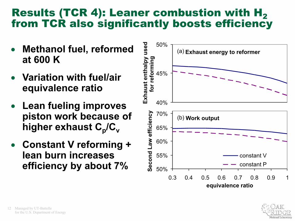
Results (TCR 4): Leaner combustion with H2from TCR also significantly boosts efficiency
• Methanol fuel, reformed at 600 K
• Variation with fuel/air equivalence ratio
• Lean fueling improves piston work because of higher exhaust Cp/Cv
• Constant V reforming + lean burn increases efficiency by about 7%
Exhaust energy to reformer
Work output
40%
45%
50%
0.3 0.4 0.5 0.6 0.7 0.8 0.9 1
Exha
ust e
ntha
lpy
used
fo
r ref
orm
ing
(a)
50%
55%
60%
65%
70%
0.3 0.4 0.5 0.6 0.7 0.8 0.9 1equivalence ratio
Seco
nd L
aw e
ffici
ency
constant Vconstant P
(b)
13 Managed by UT-Battellefor the U.S. Department of Energy
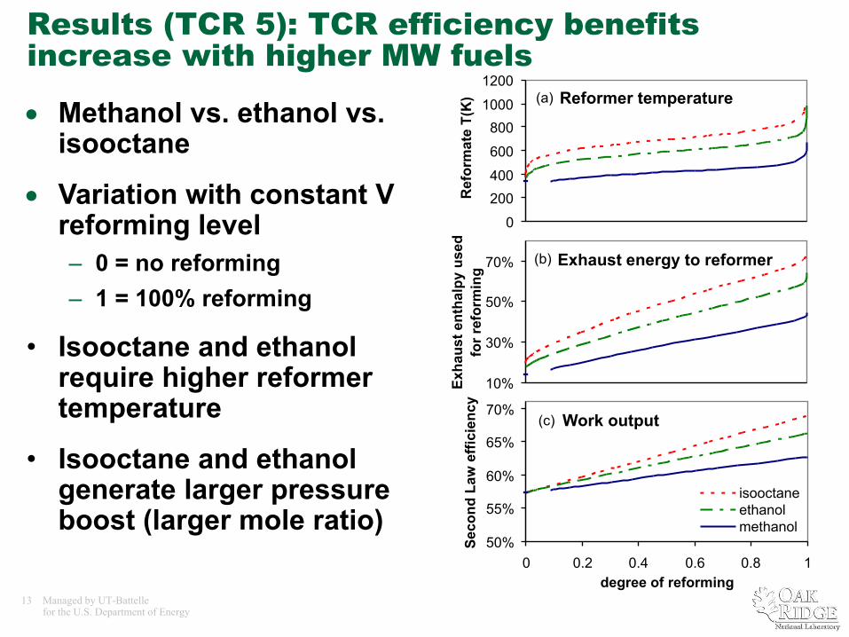
Results (TCR 5): TCR efficiency benefits increase with higher MW fuels
• Methanol vs. ethanol vs. isooctane
• Variation with constant V reforming level – 0 = no reforming– 1 = 100% reforming
• Isooctane and ethanol require higher reformer temperature
• Isooctane and ethanol generate larger pressure boost (larger mole ratio)
0
200400
600
8001000
1200
0 0.2 0.4 0.6 0.8 1degree of reforming
Ref
orm
ate
T(K
) (a)
10%
30%
50%
70%
0 0.2 0.4 0.6 0.8 1degree of reforming
Exha
ust e
ntha
lpy
used
fo
r ref
orm
ing
(b)
50%
55%
60%
65%
70%
0 0.2 0.4 0.6 0.8 1degree of reforming
Seco
nd L
aw e
ffici
ency
isooctaneethanolmethanol
(c)
Reformer temperature
Exhaust energy to reformer
Work output
14 Managed by UT-Battellefor the U.S. Department of Energy
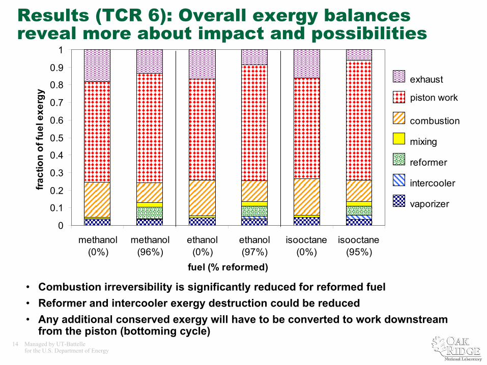
Results (TCR 6): Overall exergy balances reveal more about impact and possibilities
• Combustion irreversibility is significantly reduced for reformed fuel• Reformer and intercooler exergy destruction could be reduced • Any additional conserved exergy will have to be converted to work downstream
from the piston (bottoming cycle)
0
0.1
0.2
0.3
0.4
0.5
0.6
0.7
0.8
0.9
1
methanol(0%)
methanol(96%)
ethanol(0%)
ethanol(97%)
isooctane(0%)
isooctane(95%)
fuel (% reformed)
fract
ion
of fu
el e
xerg
y
n/aexhaust
work
combustion
mixing
reformer
intercooler
vaporizer
piston work
15 Managed by UT-Battellefor the U.S. Department of Energy
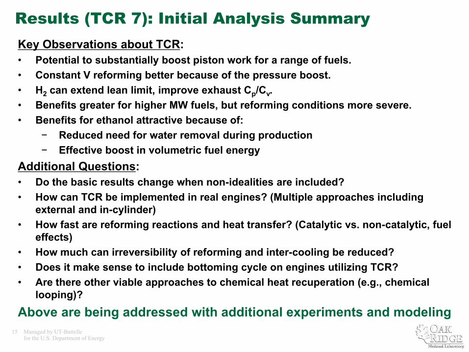
Results (TCR 7): Initial Analysis SummaryKey Observations about TCR:• Potential to substantially boost piston work for a range of fuels.• Constant V reforming better because of the pressure boost.• H2 can extend lean limit, improve exhaust Cp/Cv. • Benefits greater for higher MW fuels, but reforming conditions more severe.• Benefits for ethanol attractive because of:
− Reduced need for water removal during production− Effective boost in volumetric fuel energy
Additional Questions:• Do the basic results change when non-idealities are included?• How can TCR be implemented in real engines? (Multiple approaches including
external and in-cylinder)• How fast are reforming reactions and heat transfer? (Catalytic vs. non-catalytic, fuel
effects) • How much can irreversibility of reforming and inter-cooling be reduced?• Does it make sense to include bottoming cycle on engines utilizing TCR?• Are there other viable approaches to chemical heat recuperation (e.g., chemical
looping)?
Above are being addressed with additional experiments and modeling
16 Managed by UT-Battellefor the U.S. Department of Energy
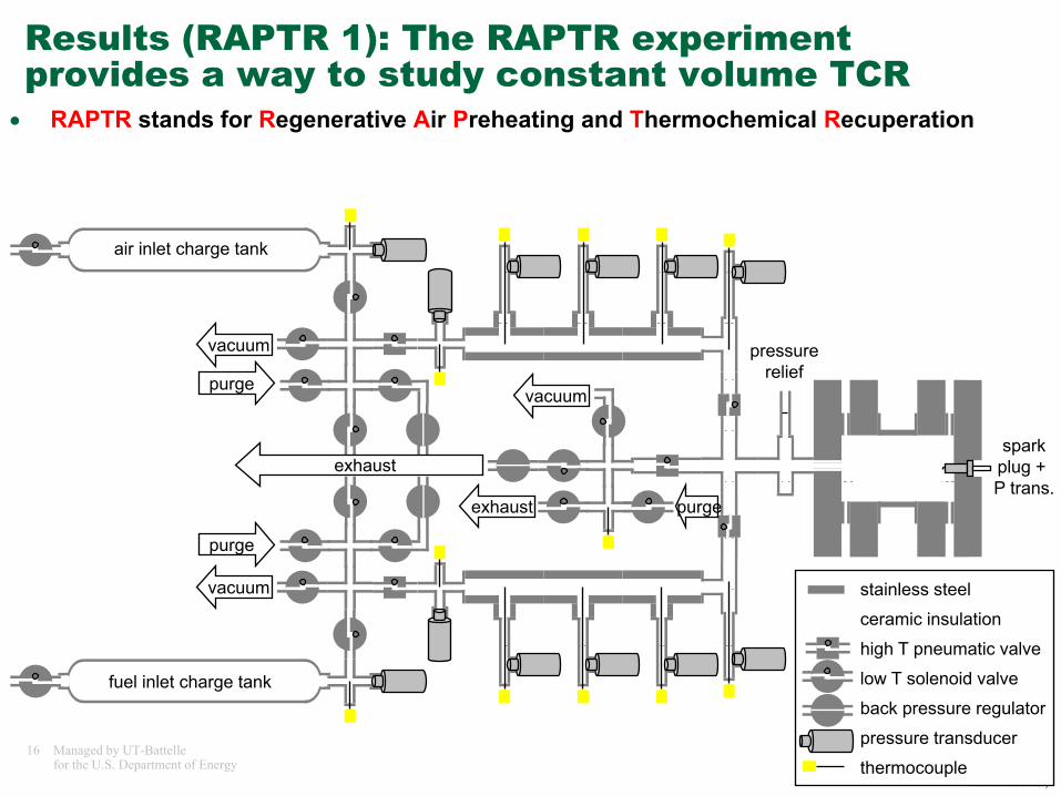
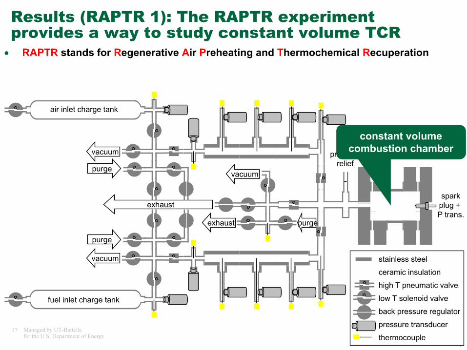
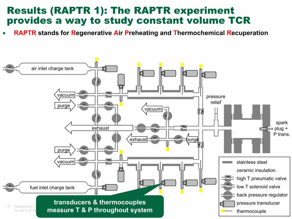
Results (RAPTR 1): The RAPTR experiment provides a way to study constant volume TCR
• RAPTR stands for Regenerative Air Preheating and Thermochemical Recuperation
pressurerelief
vacuum stainless steel
ceramic insulation
high T pneumatic valve
low T solenoid valve
back pressure regulator
pressure transducer
thermocouple
vacuum
purge
purgevacuum
exhaust purge
exhaust
air inlet charge tank
fuel inlet charge tank
sparkplug + P trans.
17 Managed by UT-Battellefor the U.S. Department of Energy
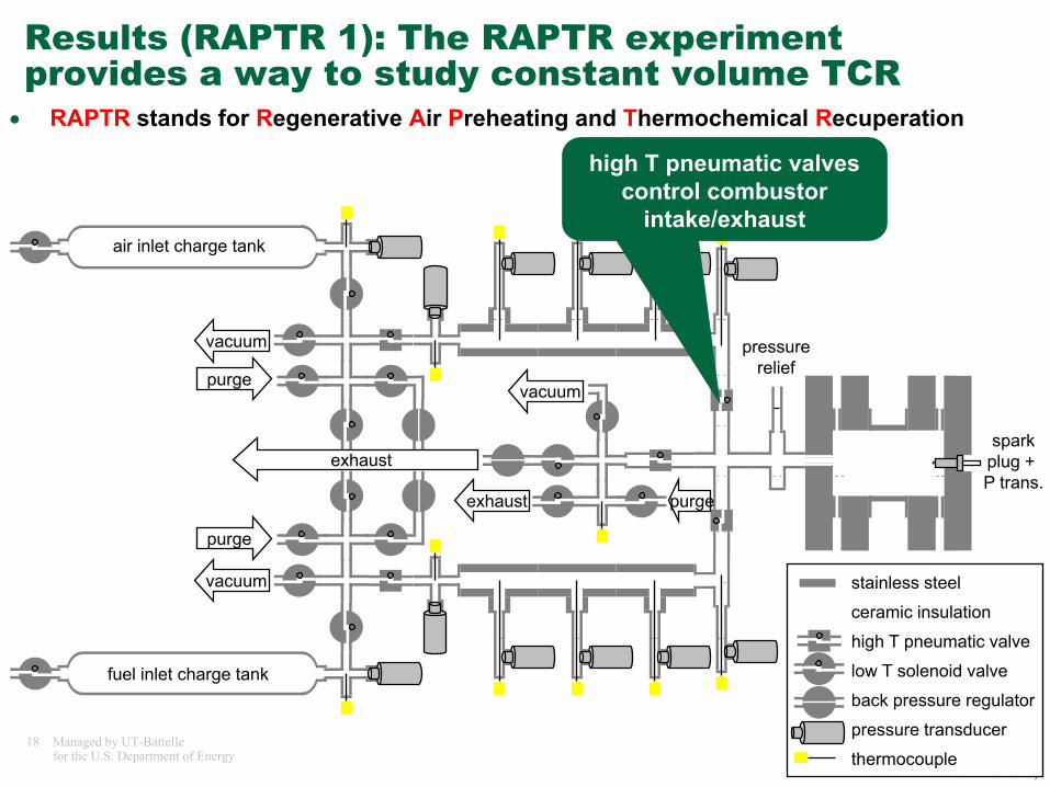
Results (RAPTR 1): The RAPTR experiment provides a way to study constant volume TCR
• RAPTR stands for Regenerative Air Preheating and Thermochemical Recuperation
pressurerelief
vacuum stainless steel
ceramic insulation
high T pneumatic valve
low T solenoid valve
back pressure regulator
pressure transducer
thermocouple
vacuum
purge
purgevacuum
exhaust purge
exhaust
air inlet charge tank
fuel inlet charge tank
sparkplug + P trans.
constant volume combustion chamber
18 Managed by UT-Battellefor the U.S. Department of Energy
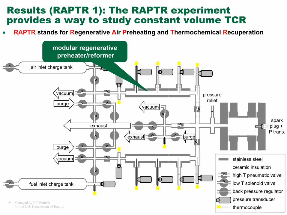
Results (RAPTR 1): The RAPTR experiment provides a way to study constant volume TCR
• RAPTR stands for Regenerative Air Preheating and Thermochemical Recuperation
pressurerelief
vacuum stainless steel
ceramic insulation
high T pneumatic valve
low T solenoid valve
back pressure regulator
pressure transducer
thermocouple
vacuum
purge
purgevacuum
exhaust purge
exhaust
air inlet charge tank
fuel inlet charge tank
sparkplug + P trans.
high T pneumatic valves control combustor
intake/exhaust
19 Managed by UT-Battellefor the U.S. Department of Energy
Results (RAPTR 1): The RAPTR experiment provides a way to study constant volume TCR
• RAPTR stands for Regenerative Air Preheating and Thermochemical Recuperation
pressurerelief
vacuum stainless steel
ceramic insulation
high T pneumatic valve
low T solenoid valve
back pressure regulator
pressure transducer
thermocouple
vacuum
purge
purgevacuum
exhaust purge
exhaust
air inlet charge tank
fuel inlet charge tank
sparkplug + P trans.
modular regenerativepreheater/reformer
20 Managed by UT-Battellefor the U.S. Department of Energy
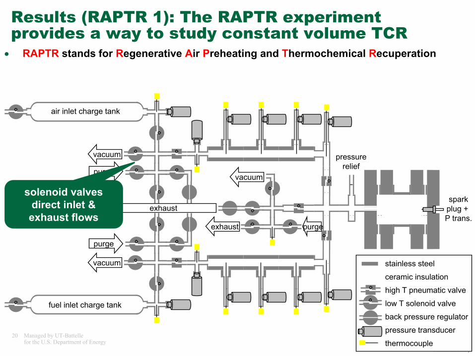
Results (RAPTR 1): The RAPTR experiment provides a way to study constant volume TCR
• RAPTR stands for Regenerative Air Preheating and Thermochemical Recuperation
pressurerelief
vacuum stainless steel
ceramic insulation
high T pneumatic valve
low T solenoid valve
back pressure regulator
pressure transducer
thermocouple
vacuum
purge
purgevacuum
exhaust purge
exhaust
air inlet charge tank
fuel inlet charge tank
sparkplug + P trans.
solenoid valves direct inlet & exhaust flows
21 Managed by UT-Battellefor the U.S. Department of Energy
Results (RAPTR 1): The RAPTR experiment provides a way to study constant volume TCR
• RAPTR stands for Regenerative Air Preheating and Thermochemical Recuperation
pressurerelief
vacuum stainless steel
ceramic insulation
high T pneumatic valve
low T solenoid valve
back pressure regulator
pressure transducer
thermocouple
vacuum
purge
purgevacuum
exhaust purge
exhaust
air inlet charge tank
fuel inlet charge tank
sparkplug + P trans.
transducers & thermocouples measure T & P throughout system
22 Managed by UT-Battellefor the U.S. Department of Energy
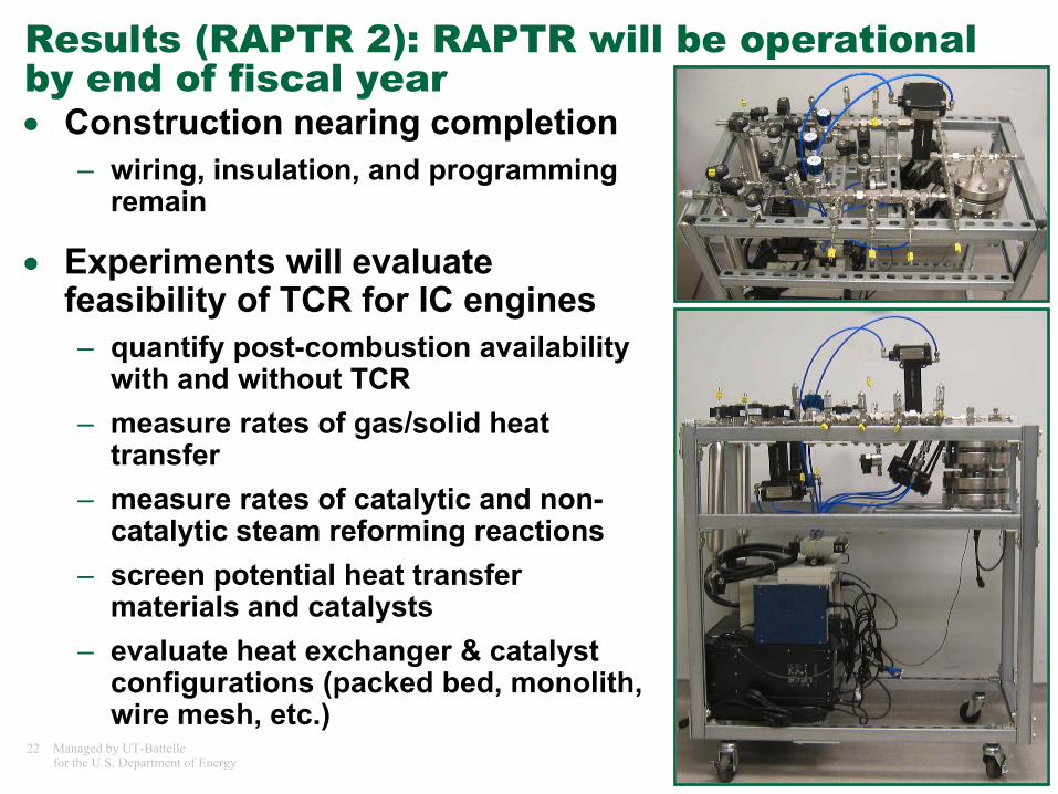
Results (RAPTR 2): RAPTR will be operational by end of fiscal year• Construction nearing completion
– wiring, insulation, and programming remain
• Experiments will evaluate feasibility of TCR for IC engines– quantify post-combustion availability
with and without TCR– measure rates of gas/solid heat
transfer– measure rates of catalytic and non-
catalytic steam reforming reactions– screen potential heat transfer
materials and catalysts– evaluate heat exchanger & catalyst
configurations (packed bed, monolith, wire mesh, etc.)
23 Managed by UT-Battellefor the U.S. Department of Energy
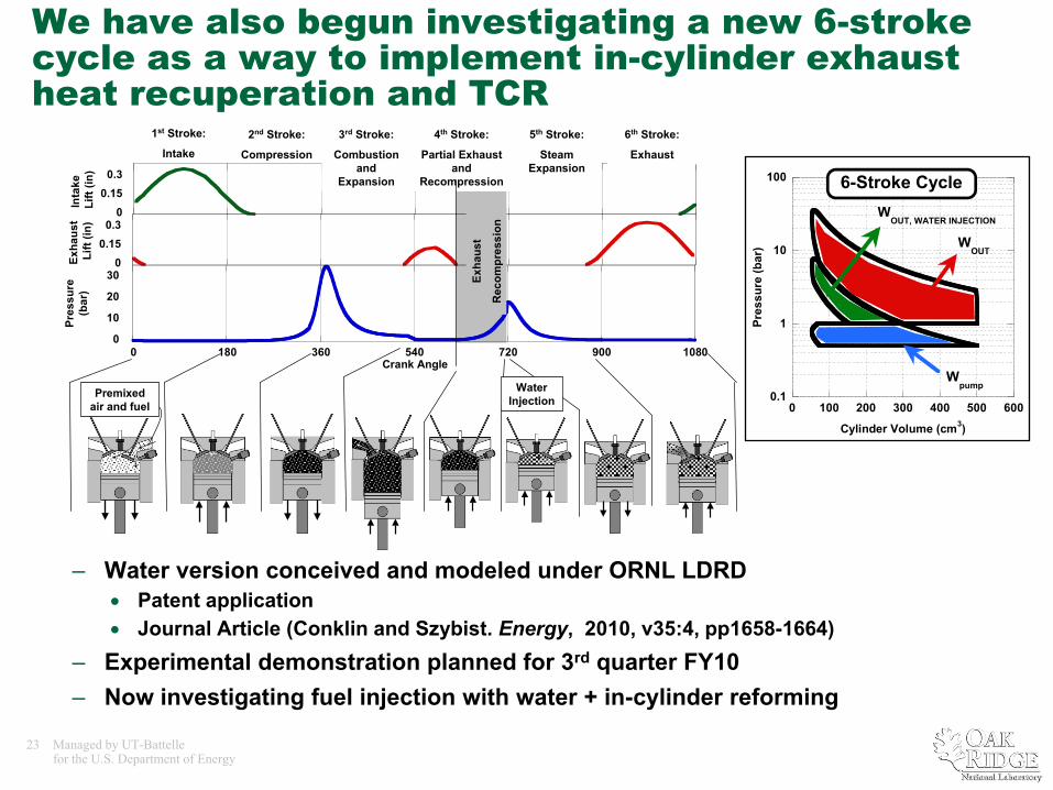
We have also begun investigating a new 6-stroke cycle as a way to implement in-cylinder exhaust heat recuperation and TCR
0.1
1
10
100
0 100 200 300 400 500 600
Pres
sure
(bar
)
Cylinder Volume (cm3)
Wpump
WOUT
WOUT, WATER INJECTION
6-Stroke Cycle
0
10
20
30
0 180 360 540 720 900 1080
Pres
sure
(bar
)
Crank Angle
00.15
0.3
Exha
ust
Lift
(in)
00.15
0.3
Inta
ke
Lift
(in)
1st Stroke:
Intake2nd Stroke:
Compression
3rd Stroke:
Combustion and
Expansion
4th Stroke:
Partial Exhaust and
Recompression
5th Stroke:
Steam Expansion
6th Stroke:
Exhaust
Premixed air and fuel
Exha
ust
Rec
ompr
essi
on
Water Injection
– Water version conceived and modeled under ORNL LDRD• Patent application• Journal Article (Conklin and Szybist. Energy, 2010, v35:4, pp1658-1664)
– Experimental demonstration planned for 3rd quarter FY10– Now investigating fuel injection with water + in-cylinder reforming
24 Managed by UT-Battellefor the U.S. Department of Energy
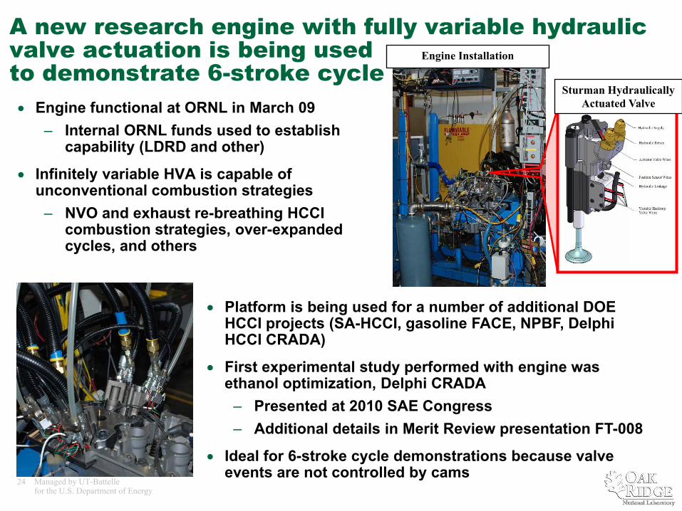
A new research engine with fully variable hydraulic valve actuation is being used to demonstrate 6-stroke cycle• Engine functional at ORNL in March 09
– Internal ORNL funds used to establish capability (LDRD and other)
• Infinitely variable HVA is capable of unconventional combustion strategies
– NVO and exhaust re-breathing HCCI combustion strategies, over-expanded cycles, and others
Engine Installation
Sturman Hydraulically Actuated Valve
• Platform is being used for a number of additional DOE HCCI projects (SA-HCCI, gasoline FACE, NPBF, Delphi HCCI CRADA)
• First experimental study performed with engine was ethanol optimization, Delphi CRADA
– Presented at 2010 SAE Congress– Additional details in Merit Review presentation FT-008
• Ideal for 6-stroke cycle demonstrations because valve events are not controlled by cams
25 Managed by UT-Battellefor the U.S. Department of Energy
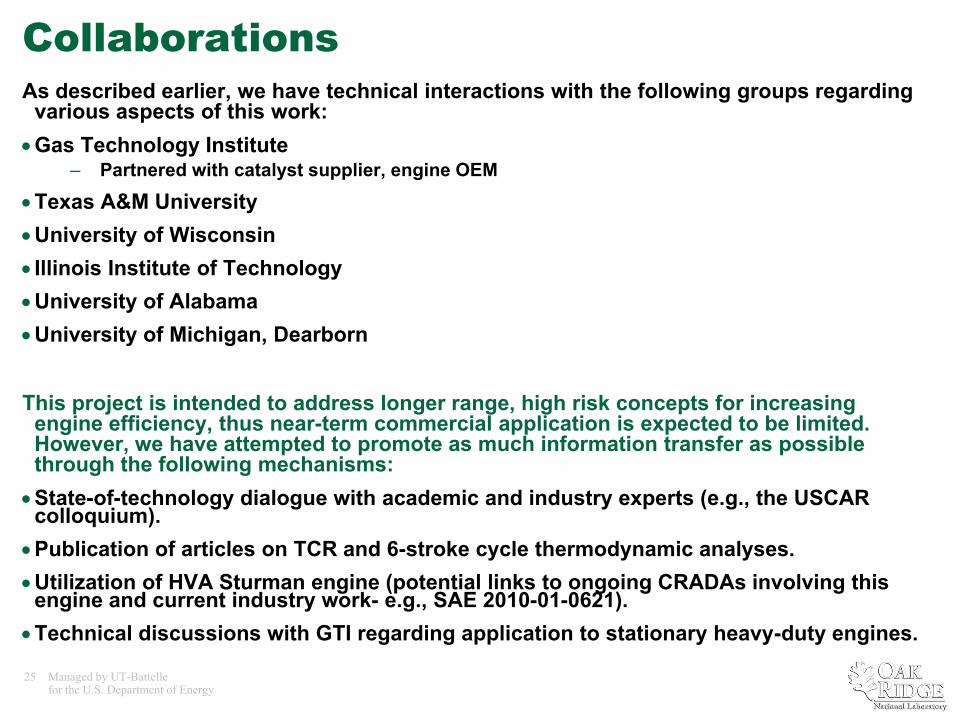
CollaborationsAs described earlier, we have technical interactions with the following groups regarding
various aspects of this work:•Gas Technology Institute
– Partnered with catalyst supplier, engine OEM
•Texas A&M University •University of Wisconsin • Illinois Institute of Technology•University of Alabama•University of Michigan, Dearborn
This project is intended to address longer range, high risk concepts for increasing engine efficiency, thus near-term commercial application is expected to be limited. However, we have attempted to promote as much information transfer as possible through the following mechanisms:
•State-of-technology dialogue with academic and industry experts (e.g., the USCAR colloquium).
•Publication of articles on TCR and 6-stroke cycle thermodynamic analyses.•Utilization of HVA Sturman engine (potential links to ongoing CRADAs involving this
engine and current industry work- e.g., SAE 2010-01-0621).•Technical discussions with GTI regarding application to stationary heavy-duty engines.
26 Managed by UT-Battellefor the U.S. Department of Energy
Planned Activities• Near term
– 0-D thermodynamic modeling of TCR in 6-stroke cycle– Complete RAPTR construction and shakedown – Continued lab characterization of reformer catalysts– Initial experimental studies of exhaust heat recuperation in
RAPTR and Sturman engine– Initial thermodynamic evaluation of chemical looping as an
alternative heat recuperation method for engines
• Longer term– Extended RAPTR and Sturman experiments– More detailed cycle simulations with non-ideal engine
components– Theoretical analysis of possible major changes to engine
architecture (along lines proposed in USCAR colloquium)
27 Managed by UT-Battellefor the U.S. Department of Energy
Summary
• Thermochemical exhaust heat recuperation (TCR) has the theoretical potential for increasing peak IC engine efficiency by more than 10%.
• A large part of this potential TCR benefit is associated with the pressure boost generated by reforming.
• A highly flexible constant volume bench-top combustor and HVA engine are being set up to experimentally evaluate this potential.
• Further analytical studies are underway to explore how direct exhaust heat recuperation and TCR might be exploited in both current and future engine architectures.
Stuart Daw865-946-1341