Embed Size (px)
Citation preview
Scholars' Mine Scholars' Mine
Professional Degree Theses Student Theses and Dissertations
1884
Stresses in suspension bridges Stresses in suspension bridges
William M. Claypool
Follow this and additional works at: https://scholarsmine.mst.edu/professional_theses
Part of the Civil Engineering Commons
Department: Department:
Recommended Citation Recommended Citation Claypool, William M., "Stresses in suspension bridges" (1884). Professional Degree Theses. 133. https://scholarsmine.mst.edu/professional_theses/133
This Thesis - Open Access is brought to you for free and open access by Scholars' Mine. It has been accepted for inclusion in Professional Degree Theses by an authorized administrator of Scholars' Mine. This work is protected by U. S. Copyright Law. Unauthorized use including reproduction for redistribution requires the permission of the copyright holder. For more information, please contact [email protected].
Stresses —in —
Suspension Bridges
Suspension Bridges1
A suspension bridge is one in which the roadway over the stream or span to be crossed is suspended from chains or wire ropes.A suspension bridge consists of the towers or piers over which the main chains or cables pass; the anchorages to which the ends of the cables are attached; the main chains or cables from which the roadway is suspended; the suspending rods or chains which connect the roadway with the cable and the roadway.The sub-structure consists of the foundations, piers &c. The super-structure consists of the roadway and the chains or cables.
T owers-The towers, frequently termed
piers, are generally made of masonry, although iron has sometimes been
2used. The particular kind or form of towers will depend to some extent upon the locality and character of surroundings. Their dimensions will depend upon their height and the amount of strains they will haves to resist.Where the cables pass over the towers are saddles. Our construction of saddles in which the cable passed our friction rollers rigidly attached to the top of the pier, allows the cable to slip backwards and forwards over it with comparatively little friction, so that the stress on the cable may be taken as equal on both sides of the saddle.In another construction the chain is secured to its saddle, which, however, is free to move horizontally on the top of the piers.In the first form of saddles the resultant pressure on the pier will not be vertical unless the chain
3leaves the pier at an equal inclination on each side, and even when the bridge is designed with an equal slope of chain on both sides of the pier, a change in the distribution of weight due to any passing load, will cause some departure from the equal slope of the chains, and therefore from the truly vertical pressure of the piers. This departure is easily allowed for in the design of the bridge piers.The friction on the saddle renders the assumption of equal stresses on each side slightly incorrect, and with this type of saddle, care must be taken to provide against the wear produced by the motion of the chain.In the second type, the use of rollers under the solid saddle leaves the motion of the saddle very free; its resultant pressure on the tower is always vertical, and the chains may
4leave the tower at any angle, equal or unequal.The chain must in no case be rigidly attached to the pier, unless the pier, or rather support in this instance, is free to rock on its base, or for example, when the place of the pier is taken by iron struts working on a horizontal axis.Anchorage
If the shore or bank be of rock, a vertical passage should be excavated and a strong iron plate placed in the bottom and firmly imbedded in the side of the passage. Through this plate the ends of the cables are passed and secured on the under side.After the cables are put in place, the passage should be filled with concrete and masonry.If the bank is not suitable for the
5anchorage, a heavy mass of masonry should be built of large blocks of cut- stone well bonded together for this purpose. In this case it is well to construct a passage way so that the chains and fastenings may at any time be examined. The mass of masonry or the natural rock to which the ends of the cables are fastened is frequently called the abutment.Its stability must be greater than the tension of the cables. Its weight and thickness must be sufficient to prevent its being overturned, and its center of resistance must be in safe limits. The calculations in regard to the anchorage, when it is artificial, properly belong with the suspension bridge but I have left them out, since they can be very appropriately included in masonry.
6Cables
These may be made of iron bars connected by eye bar and pin joints, of iron links &c, but the custom now is to use wire ropes or cables. The smallest number of cables is two, one to support each side of the roadway. Generally more than two are used, since, for the same amount of material, they offer at least the same resistance, are more accurately manufactured are liable to less danger of accident, and can be more easily put in place and replaced than a single cable of an equal amount of material.Great care is taken to give each wire the same degree of tension. To ensure this, it used to be thought necessary to strain each wire separately over the actual piers, or piers similarly placed, and bind them together when hanging, strained by their own weight with the dip proposed for the bridge.It was also thought essential that each rope
7should be an aggregate of parallel wires, not spun, as in a rope. Experiment, however, has shown that wire ropes spun with a machine which does not put a twist in each wire, but lays it helically and untwisted, and with no straight central wire, are as strong as wire ropes of equal weight made with straight wires.It is the custom now to make the cable of wire 1/6” to 1/5” in diameter, and bring them to a cylindrical shape by a spiral wrapping of wire. The wires are coated with varnish before being bound up, and the cable itself is suitably protected from atmospheric influences.Suspension Rods
When the cable is composed of links or bars, they are attached directly to them. If of rope, the suspension rod is attached to a collar of iron of suitable shape bent around the cable, or to a saddle piece resting on it. When there are two cables,
8care must be taken to distribute the load upon the cables according to their degree of strength.Roadway
The roadway bearers are supported by the suspension rods. On the bearers are laid longitudinal joists, and on them the planking, or the planking is laid directly on the roadway bearers. The latter are stiffened by diagonal ties of iron placed horizontally between each pair of roadway bearers.General Principles
The great merit of asuspension bridge is its cheapness, arising from the comparatively small quantity of material required to carry a given passing load across a given span. This cheapness may be seen more clearly by considering an example. A man might cross a chasm of 100’ by hanging to a steel wire .21” in diameter, dipping 10’;
9the weight of the iron would be 12.75 lbs.A wrought iron beam of rectangular cross-section three times as deep as it is broad, would have to be about 27” deep and 9” broad to carry him and its own weight. It would be weigh 87,500 lbs.An iron I beam of best construction 10’ deep would weigh about 120 lbs. In each case 4’ have been allowed for bearings at the end of the spans. The enormous differences would not exist if the beam and wire had only to carry the man, even then there would be a great difference in favor of the wire. The main difference arises from the fact that the bridge has to carry its own weight.The chief merit of a suspension bridge does not, therefore, come into play, until the weight of the rope or beam is considerable when compared with the platform and rolling load; for although the chain will for any given load be
10lighter than a beam, the saving in this respect will, for small spans, be more than compensated by the expense of the anchorages.The disadvantages of the suspension bridge are numerous. A change in the distribution of the load causes a very sensible deformation of the structure, for the cable of the suspension bridge must adapt is form to the new position of the load, whereas in the beam the deformation is hardly sensible, equilibrium being attained by a new distribution of the stresses through the material.This flexibility of the suspension bridge renders it unsuitable for the passage of a railway train at any considerable speed. The platform rises up as a wave in front of any rapidly advancing load, and the masses in motion produce stresses much greater than those which would result from
11the same weights when at rest.The kinetic effect of the oscillations produced by bodies of men marching, or by impulses due to wind, give rise to strains which cannot be foreseen.
12
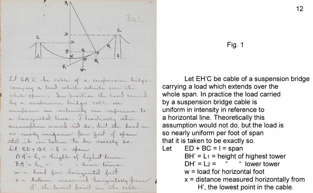
Fig. 1
Let EH’C be cable of a suspension bridge carrying a load which extends over the whole span. In practice the load carried by a suspension bridge cable is uniform in intensity in reference to a horizontal line. Theoretically this assumption would not do, but the load is so nearly uniform per foot of span that it is taken to be exactly so.Let ED + BC = I = span
BIT = Li = height of highest tower DH’ = L2 = “ “ lower towerw = load for horizontal foot
x = distance measured horizontally fromH’, the lowest point in the cable.
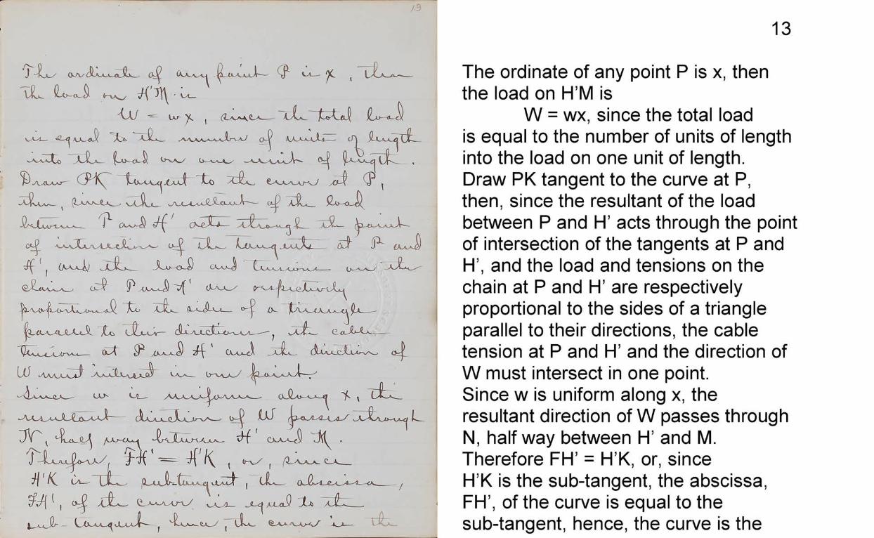
13The ordinate of any point P is x, then the load on H’M is
W = wx, since the total load is equal to the number of units of length into the load on one unit of length.Draw PK tangent to the curve at P, then, since the resultant of the load between P and H’ acts through the point of intersection of the tangents at P and H’, and the load and tensions on the chain at P and H’ are respectively proportional to the sides of a triangle parallel to their directions, the cable tension at P and H’ and the direction of W must intersect in one point.Since w is uniform along x, the resultant direction of W passes through N, halfway between H’ and M.Therefore FIT = H’K, or, since H’K is the sub-tangent, the abscissa, FIT, of the curve is equal to the sub-tangent, hence, the curve is the
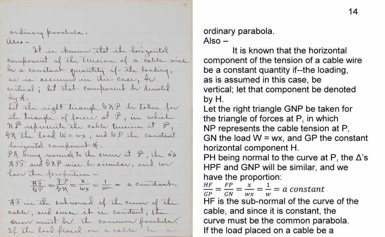
14ordinary parabola.Also -
It is known that the horizontal component of the tension of a cable wire be a constant quantity if—the loading, as is assumed in this case, be vertical; let that component be denoted by H.Let the right triangle GNP be taken for the triangle of forces at P, in which NP represents the cable tension at P,GN the load W = wx, and GP the constant horizontal component H.PH being normal to the curve at P, the A ’s HPF and GNP will be similar, and we have the proportion:HF FP X 1— = — = — = — = a constan tGP GN wx wHF is the sub-normal of the curve of the cable, and since it is constant, the curve must be the common parabola.If the load placed on a cable be a
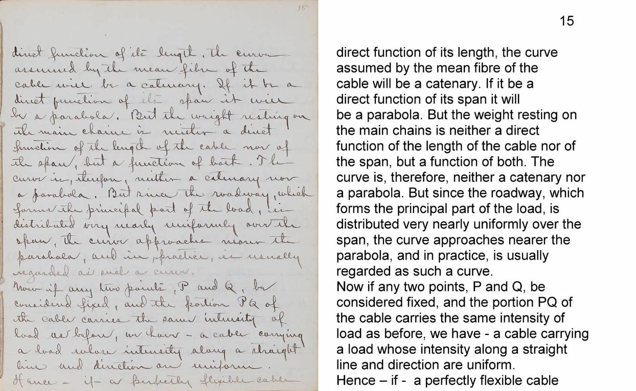
15direct function of its length, the curve assumed by the mean fibre of the cable will be a catenary. If it be a direct function of its span it will be a parabola. But the weight resting on the main chains is neither a direct function of the length of the cable nor of the span, but a function of both. The curve is, therefore, neither a catenary nor a parabola. But since the roadway, which forms the principal part of the load, is distributed very nearly uniformly over the span, the curve approaches nearer the parabola, and in practice, is usually regarded as such a curve.Now if any two points, P and Q, be considered fixed, and the portion PQ of the cable carries the same intensity of load as before, we have - a cable carrying a load whose intensity along a straight line and direction are uniform.Hence - if - a perfectly flexible cable
16
carry a load uniform in direction and intensity in reference to a straight line, the cable will assume the form of an ordinary parabola whose axis will be parallel to the loading.
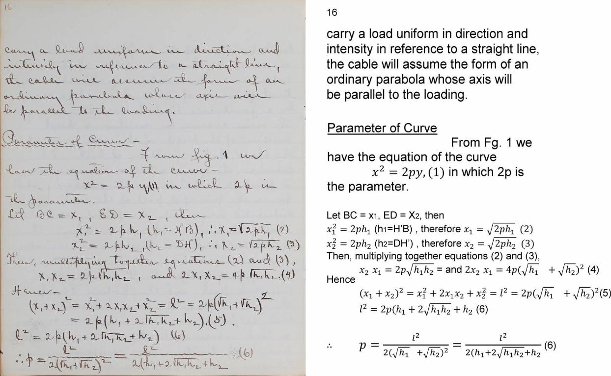
Parameter of CurveFrom Fg. 1 we
have the equation of the curvex l 2 = 2 py,(1) in which 2p is
the parameter.
Let BC = xi, ED = X2, thenx2 = 2ph1 (hi=H’B ), therefore xt = (2)x2 - 2 ph2(h2=DH’) , therefore x2 - 2 (3)Then, multiplying together equations (2) and (3),
x2 x1 = 2p jh1hz = and 2x2 x± = 4p(Jh[ + -y/ 2)2 (4)Hence
(*i + x 2) 2 = x l + 2x xx 2 + = 2 p ( J h 1 +
l 2 = 2 p ( h 1 + 2yJ h 1h 2 + h 2 (6)
l2 l2^ 2 (_sj hi + [h2)2 2(hi+2 / hih2+h2
17
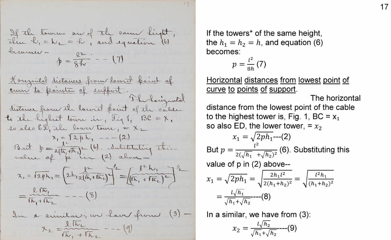
If the towers* of the same height, the h± = h2 = h, and equation (6) becomes:
VHorizontal distances from lowest point of curve to points of support.
The horizontaldistance from the lowest point of the cable to the highest tower is, Fig. 1, BC = Xi so also ED, the lower tower, = x2
*1 = y[2phi— (2)
But P = 2 (6)- Substitutin9 thisvalue of p in (2) above--Xl = ^ = J ^ Z Z =
_ hua____(g)V^T+a/^2
In a similar, we have from (3):_ ly/x2 = Jhl+Jhl— (9)
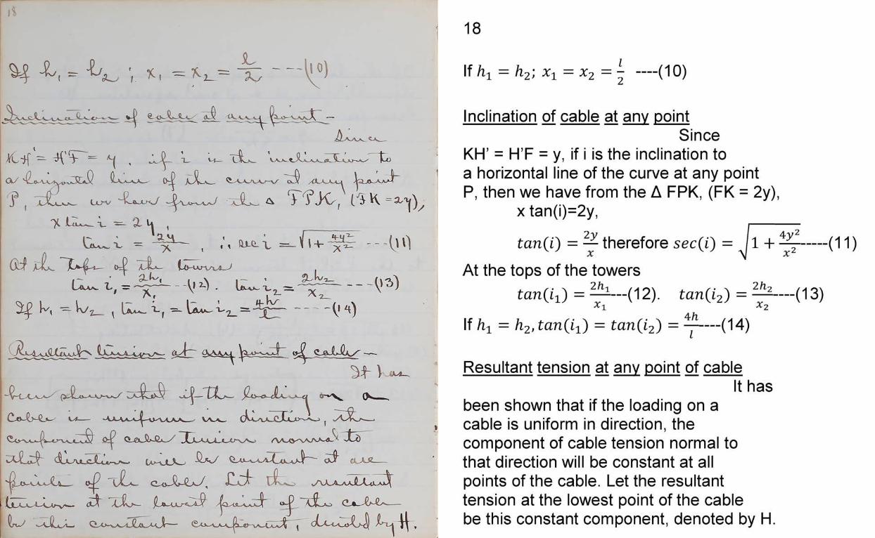
18If h = h2; x1 = x 2 = l- — (10)
Inclination of cable at any pointSince
KH’ = H’F = y, if i is the inclination to a horizontal line of the curve at any point P, then we have from the A FPK, (FK = 2y),
x tan(i)=2y,
tan(i) = — therefore sec(i) = 4 y 2 X 2
(11)
At the tops of the towerstan(i i ) = ^ — (12). tan(i2) = ^ — (13)Xi *241If /i -l = h2,tan(i1') = tan(i2) = —------ (14)
Resultant tension at any point of cableIt has
been shown that if the loading on a cable is uniform in direction, the component of cable tension normal to that direction will be constant at all points of the cable. Let the resultant tension at the lowest point of the cable be this constant component, denoted by H.
19
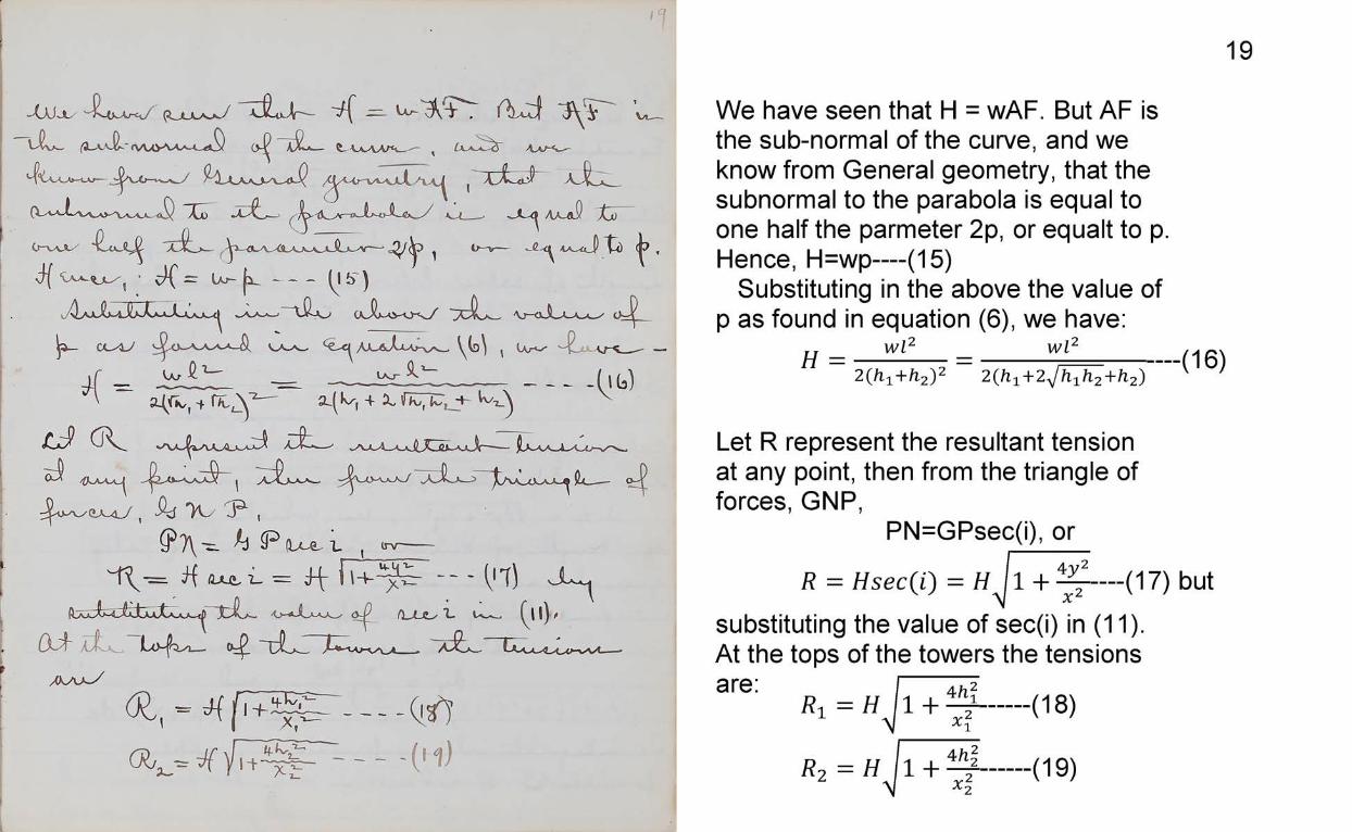
We have seen that H = wAF. But AF is the sub-normal of the curve, and we know from General geometry, that the subnormal to the parabola Is equal to one half the parmeter 2p, or equalt to p. Hence, H=wp— (15)
Substituting in the above the value of p as found in equation (6), we have:
H _ W*2 _ W*2______________________ H Q \
2 (ft1+h2)2 2(h1+2A//l1ft2+ l2 )
Let R represent the resultant tension at any point, then from the triangle of forces, GNP,
PN=GPsec(i), or
R = Hsec(i) = H l l + ^ — (17) butsubstituting the value of sec(i) in (11).At the tops of the towers the tensions are:
(18)R1 = H\
A h 21 x:
R ,= H / IX t
(19)
20
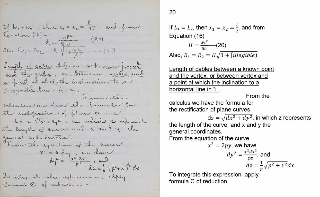
If L i = L2, then xx = x2 = -, and from Equation (16)
H = ^ — (20)8 h v ’___________Also, = R2 = H ^/l + [illegible)
Length of cables between a known point and the vertex, or between vertex and a point at which the inclination to a horizontal line in “i”.
From thecalculus we have the formula for the rectification of plane curves
dz = j d x 2 + dy2, in which z represents the length of the curve, and x and y the general coordinates.From the equation of the curve
x2 = 2 py ,we havex 2d x 2
pz ’and
dz = - J p 2 +p vTo integrate this expression, apply formula C of reduction.
21
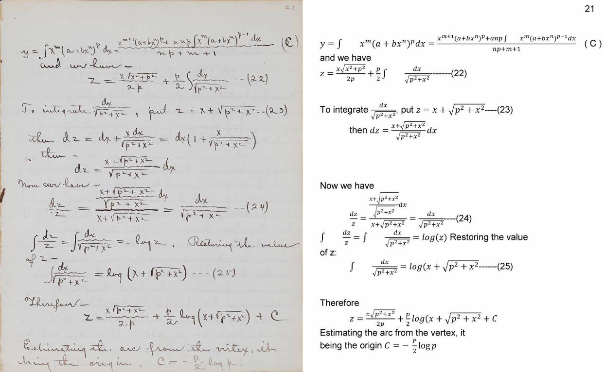
y = J x"»(g + bxny d x = x j ^ bp g +b(C )
and we haven p + m + l
x J x 2 + p 2 , p fz = -----------h -2 p 2 J
dxyJp2+X‘ --------- (22)
To integrate dxIp2 +X2» put z = X + Vp2 + * 2— (23)
then dz = x+/ p +x dxylV2+X2
Now we have2 j.y2
dz
x+ p +xp2+x2
-dxdx - - ( 24)
/ T = / of z:
Z x + j p 2 + x 2 j p 2 + x 2dx = log(z) Restoring the valuey jp 2+X‘
f dxyJp2+X‘ = log (x + ^/p2 + x2----- (25)
Thereforez = x v2pX + ^log(x + ^/p2 + x2 + C
Estimating the arc from the vertex, it being the origin C = - ^logp
22
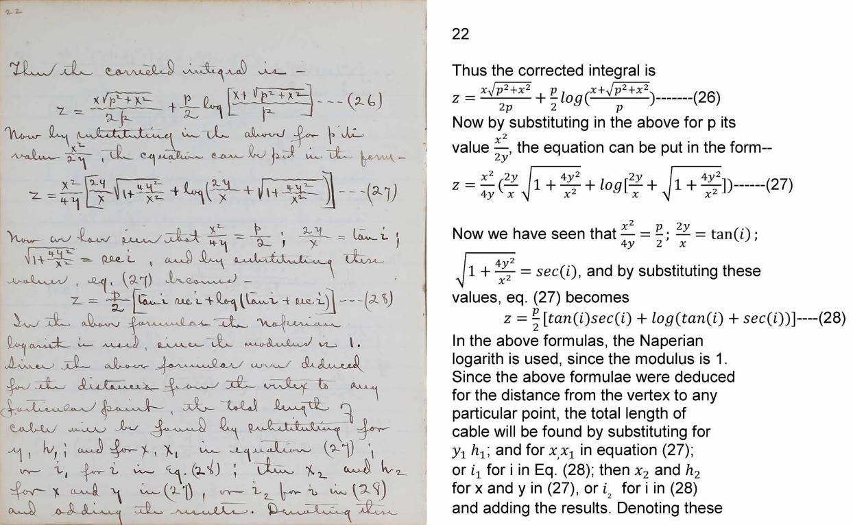
(26)Thus the corrected integral is
x J p 2+ x 2 . p , , x + J p 2+ x 2^z = —--------\-- lo a (— -------- )—2 p 2 a K p '
Now by substituting in the above for p its 2
value j-, the equation can be put in the form--
X 2y 4 y : ■2yz = — ( ^ l + ^ - + / o ^ F +4 y v x \J x^ L x i+ ^ ] >X' (27)
Now we have seen that — = - ; — = ta n (i);4 y 2 x w ll
l l +-^r = sec(i), and by substituting thesevalues, eq. (27) becomes
z = -[tan(i)sec(i) + log(tan(i) + sec(i))]— (28)In the above formulas, the Naperian logarith is used, since the modulus is 1.Since the above formulae were deduced for the distance from the vertex to any particular point, the total length of cable will be found by substituting for y1 ht \ and for x x x in equation (27); or i i for i in Eq. (28); then x2 and h2 for x and y in (27), or i2 for i in (28) and adding the results. Denoting these
results by ^ and l2, then total length will be:
k + 12— (29)A formula, which is close enough for practical purposes, and which is frequently used, is deduced as follows.In fig. 1 suppose H’P is an arc of a circle whose radius is R. The coordinates x and y are the same as before. The expression for a circular arc in the integral calculus is:
r dx r dx - x iJ -1= f = J — approximatelyJ i- fz 1 2R2
considering R very large as compared with x.
24
Suspension RodsIt is usually assumed in
the calculations relating to suspension rods, that the cable lies in a vertical beam, and that the suspension rods are vertical. Since in all cases the suspension rods are parallel to each other, the above assumption does not affect the generality of the results.If the rods are inclined, the true lengths can be found by multiplying the values obtained by the secant of the inclination of the rods to a vertical line.A flat parabola nearly coincides with a circle and we may suppose the camber to be found by a parabolic arc.
25
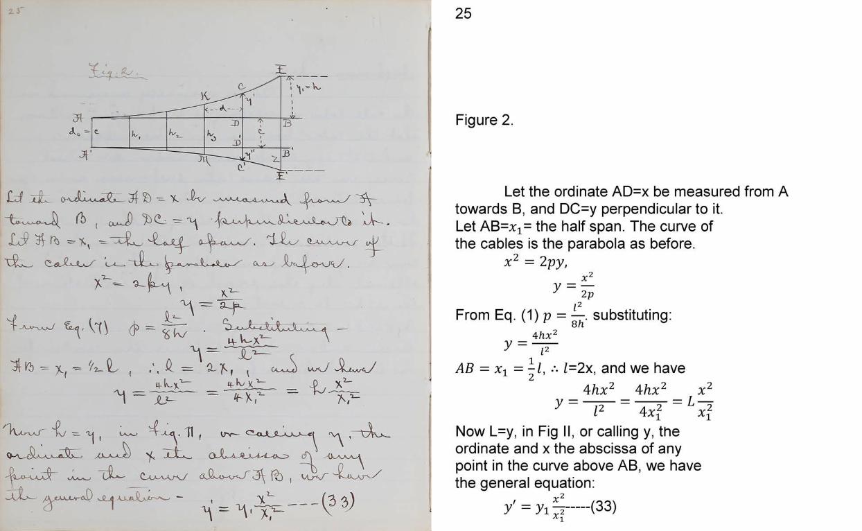
Figure 2.
Let the ordinate AD=x be measured from A towards B, and DC=y perpendicular to it.Let AB=x1= the half span. The curve of the cables is the parabola as before.
x2 = 2 py,_ X 2y ~ 2 pi2From Eq. (1) p = —. substituting:8h
4hx2y = —
AB = Xi =- l , ••• 1=2x, and we have 1 2 4hx2 Ahx2 x2 l2 4x2 ^ x2
Now L=y, in Fig II, or calling y, the ordinate and x the abscissa of any point in the curve above AB, we have the general equation:
y = yi p-(33)A ^
26
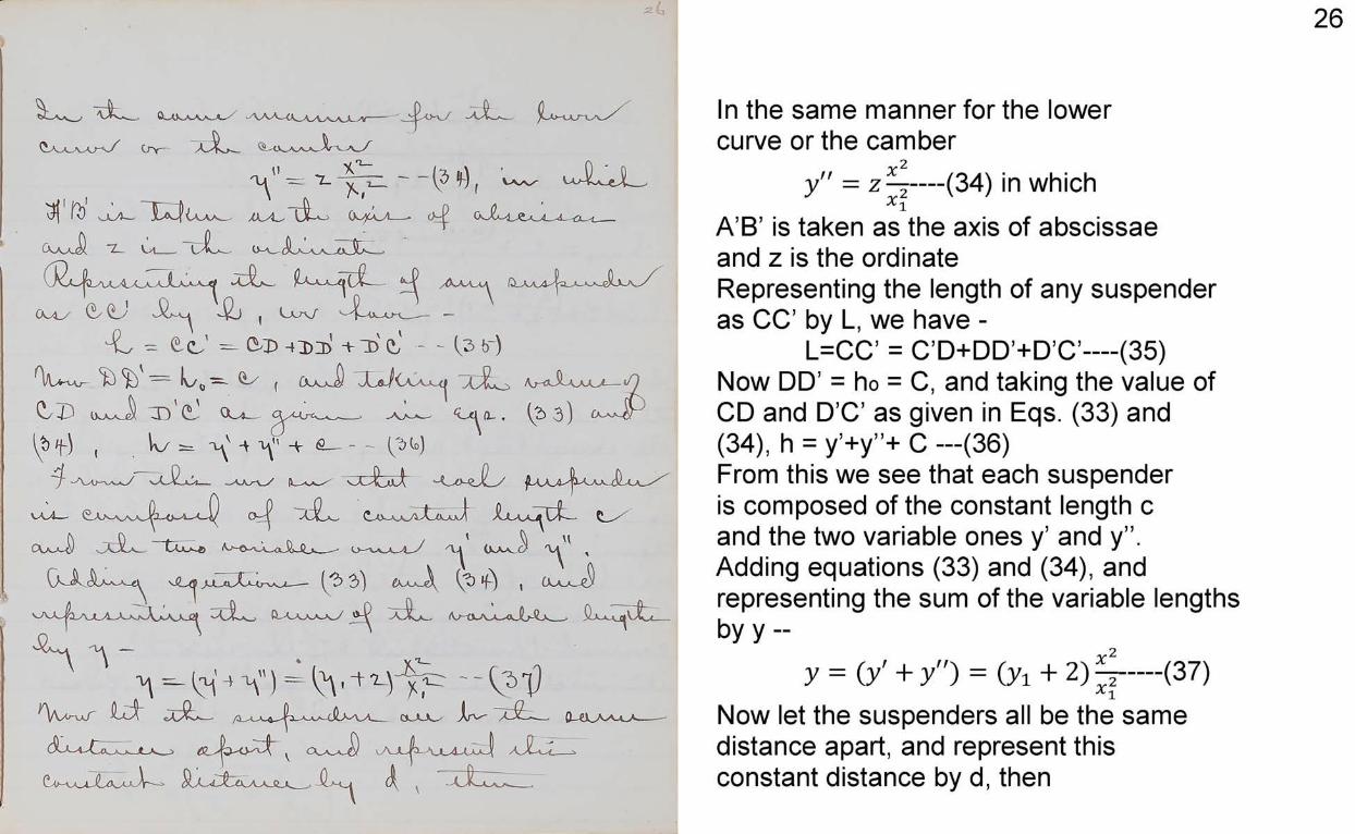
In the same manner for the lower curve or the camber
y" = z — (34) in whichX A’B’ is taken as the axis of abscissae and z is the ordinateRepresenting the length of any suspender as CC’ by L, we have -
L=CC’ = C’D+DD’+D’C’— (35)Now DD’ = ho = C, and taking the value of CD and D’C’ as given in Eqs. (33) and (34), h = y’+y”+ C —(36)From this we see that each suspender is composed of the constant length c and the two variable ones y’ and y” .Adding equations (33) and (34), and representing the sum of the variable lengths by y --
y = (y' + y") = (yi + 2 ) ~ - (37)A *t
Now let the suspenders all be the same distance apart, and represent this constant distance by d, then
27
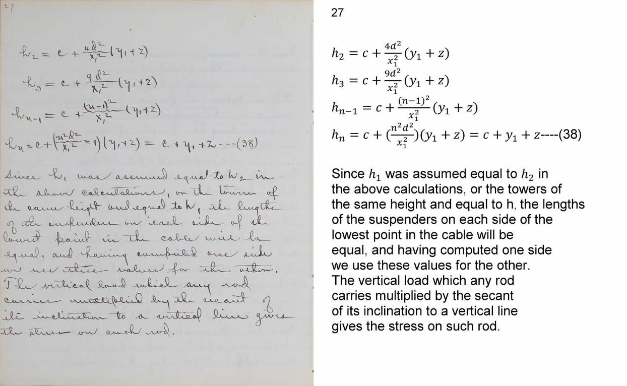
h = c + - r ( y i + z )A
^3 = c + (y i + z)
/1„_1 = c + ^ r - ( y ! + z)
K = c + (24 - ) (y i + z) = c + z— (38)
Since h± was assumed equal to h2 in the above calculations, or the towers of the same height and equal to h, the lengths of the suspenders on each side of the lowest point in the cable will be equal, and having computed one side we use these values for the other.The vertical load which any rod carries multiplied by the secant of its inclination to a vertical line gives the stress on such rod.
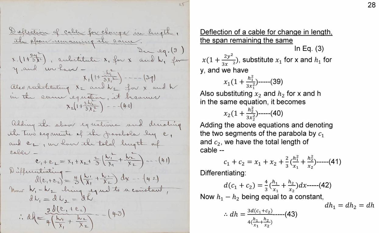
Deflection of a cable for change in length, the span remaining the same
In Eq. (3)2 y 2x ( l + r r - j) , substitute ^ for x and hx for
y, and we have
* i ( l + j | ) ---- (39)Also substituting x2 and h2 for x and h in the same equation, it becomes
* 2( ! + ^ > -----(40)Adding the above equations and denoting the two segments of the parabola by cx and c2, we have the total length of cable --
2 Jl? . Jlo,C1 + c 2 = x t + X 2 + - (■— + — )---(41)•3 a *[ A 2
Differentiating:
d ( c i+ c 2) = i ( ^ + ^ 0 * -----(42)•3 a i A 2
Now ^ - h2 being equal to a constant,dhx =
•"• dh = 3d(Cl+Cz)----- (43)
29
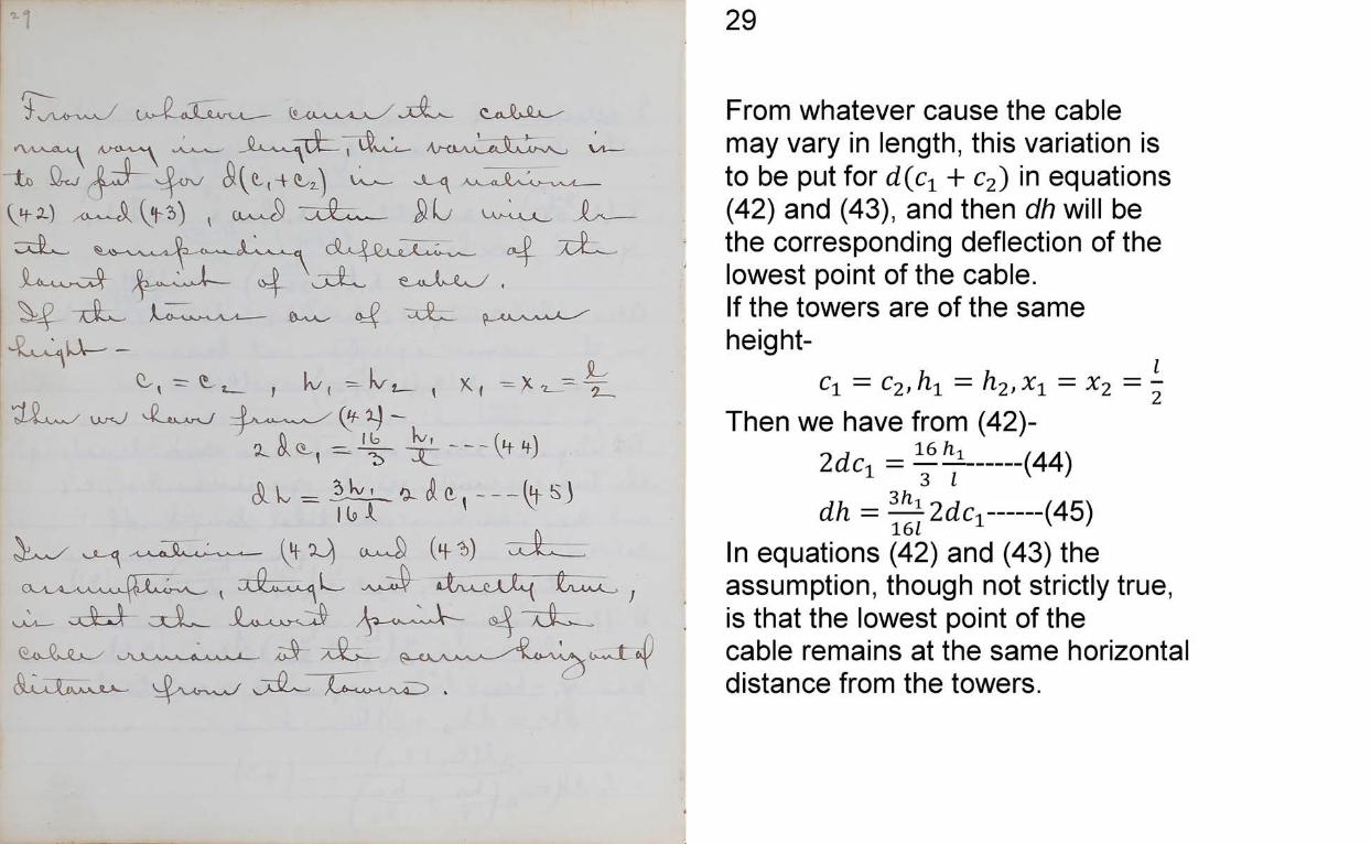
From whatever cause the cable may vary in length, this variation is to be put for d(cn + c2) in equations (42) and (43), and then dh will be the corresponding deflection of the lowest point of the cable.If the towers are of the same height
en = C2, = h.2,%1 =Then we have from (42)-
2dci = 7 7 -— <44>dh = —j2d c ,------(45)161
In equations (42) and (43) the assumption, though not strictly true, is that the lowest point of the cable remains at the same horizontal distance from the towers.
30
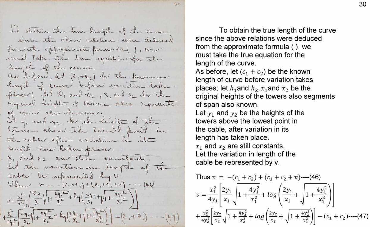
To obtain the true length of the curve since the above relations were deduced from the approximate formula (), we must take the true equation for the length of the curve.As before, let (cx + c2) be the known length of curve before variation takes places; let /i^and h2,x1and be the original heights of the towers also segments of span also known.Let y1 and y2 be the heights of thetowers above the lowest point in the cable, after variation in its length has taken place. x1 and x2 are still constants.Let the variation in length of the cable be represented by v.
Thus v = — (cj + c2) + + c2+ )— (46)
v =V 24yi
2yi l +4y! + log( 2yl + l + 4f )[ XU x\ \\ x' >1 x\ J
+ x ‘4 y
2y2x- 1 + ~ t + i°gA> o
2 y2x- + 1 + - (Cl + c2)— (47)
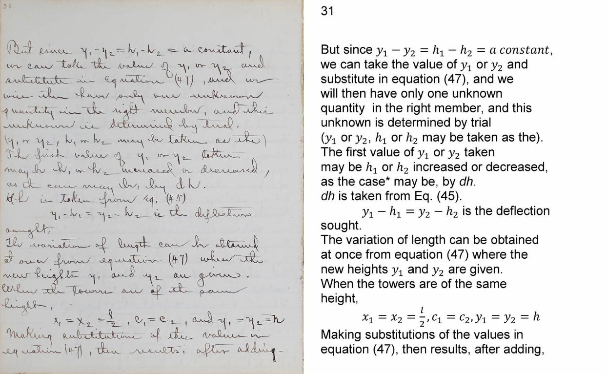
31
But since yx — y2 = hx — h2 = a constantwe can take the value of yx or y2 andsubstitute in equation (47), and wewill then have only one unknownquantity in the right member, and thisunknown is determined by trial(yi or y2, hx or h2 may be taken as the).The first value of y1 or y2 takenmay be ht or h2 increased or decreased,as the case* may be, bydh is taken from Eq. (45).
y1 - h 1 = y2 - h2 is the deflectionsought.The variation of length can be obtained at once from equation (47) where the new heights y1 and y2 are given.When the towers are of the same height,
x± = x2 = -, c± = c2,y1 = y2 =Making substitutions of the values in equation (47), then results, after adding,
32
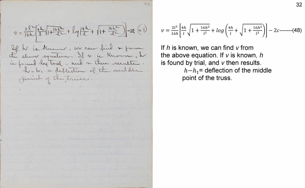
t; = 2Z216/1
4/1 L 16/l2
z >/1 + Z2 + log -2c (48)
If h is known, we can find v from the above equation. If v is known, h is found by trial, and vthen results.
h - h x- deflection of the middle point of the truss.
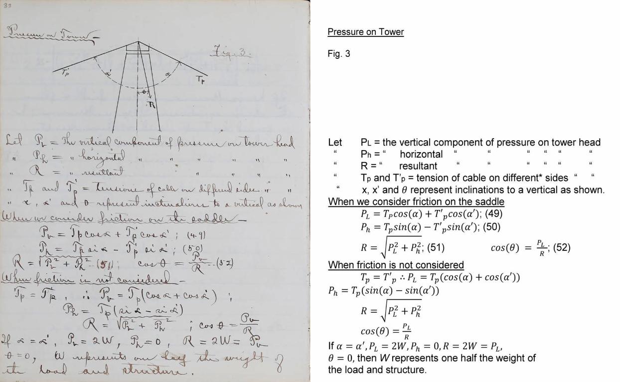
Pressure on Tower
Fig. 3
Let Pl = the vertical component of pressure on tower head“ Ph = “ horizontal “ “ ......................“ R = “ resultant “ “ “ ................
Tp and T’p = tension of cable on different* sides “ x, x’ and 6 represent inclinations to a vertical as shown.
When we consider friction on the saddle PL = TPc o s (a ) + T 'pcos(ci)\ (49)
Ph = Tpsin(a) - T'psin(a'y, (50)
R = J pl2 + P l (51) cos(0) = ^-; (52)When friction is not considered
Tp = T ’v .*. PL = Tp (c o s(a) + cos (a'))Ph = Tp(sin(a) — sin(a'))
R = Jp.~l + Plcos(0) = ^
If a = a ' ,P L = 2 W ,P h = 0 ,R = 2 W PL, 0 = 0, then IV represents one half the weight of the load and structure.
34
Bracing to resist heavy traveling loadVarious
methods have been proposed, and some of them tried, to enable a suspension bridge to resists the action of a heavily traveling load so as to undergo no more disfigurement than a girder. To ensure this in a bridge of several bays, the piers must be made very strong, and the chains securely fastened to them.The best way of bracing is by means of auxiliary girders, or a pair of straight girders of any convenient form hung from the cable by suspending rods and supporting the cross joists of the platform. These girders should be supported at each end, and also fastened down, as there are certain positions of the rolling load which would tend to raise one end of the truss. The ends should be free to move horizontally, however.
35
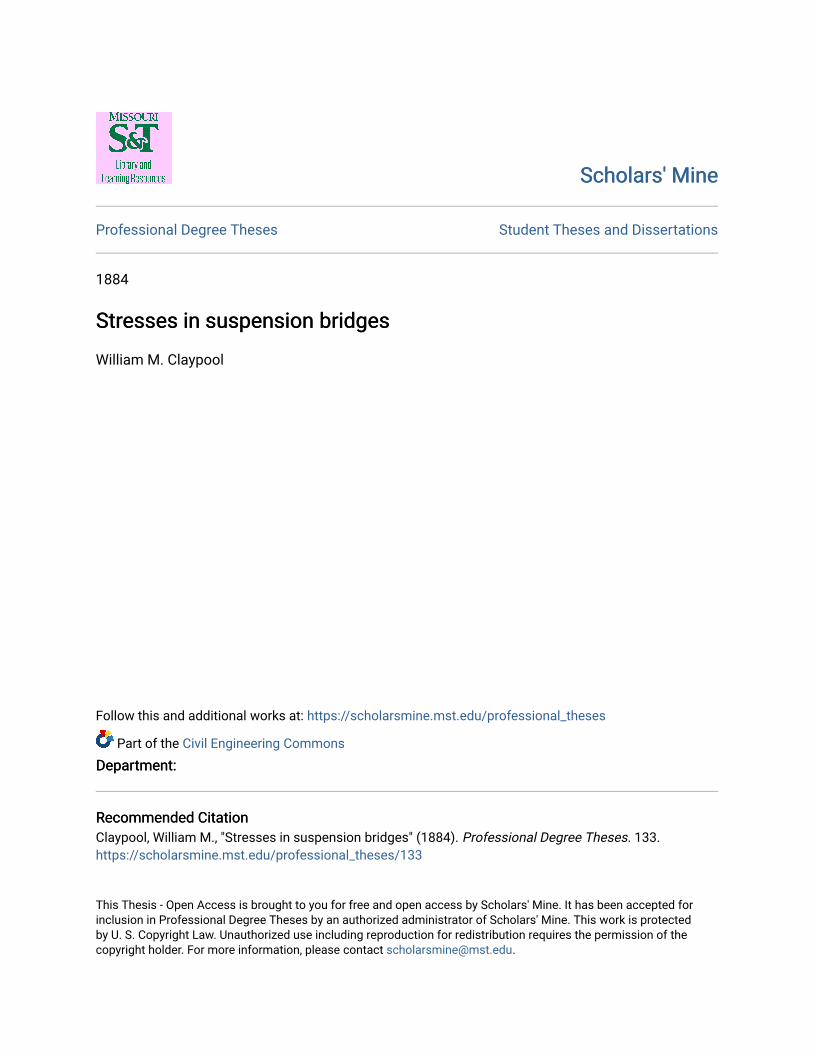
By preventing a change in the form of the cable, which is accomplished by the stiffening truss, we not only prevent very injurious undulations, but also lessen the work of computing stresses, which would be very difficult if the cable did not retain the same form. The cable will assume the same parabolic curve only when there is a uniform pull on the suspension rods from end to end.Let Tbe the uniform pull on any suspension rod, and t its intensity per unit of span. Now if p represents one panel length in the russ, T=pt Let w be the fixed load per unit of span sustained by the cables, and w’ the moving load sustained by them;Let i be the span; R the reaction at B (fig.);R ’ the reaction A. Suppose the moving load to pass on from B.Let xt be the distance from B to the front ofthe moving load. The load is supposed continuous.
36
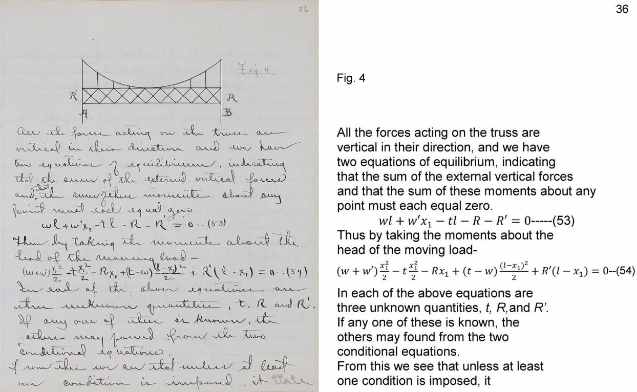
Fig. 4
All the forces acting on the truss are vertical in their direction, and we have two equations of equilibrium, indicating that the sum of the external vertical forces and that the sum of these moments about any point must each equal zero.
wl + w'xx — tl — R — R' = 0---- (53)Thus by taking the moments about the head of the moving load-(w + w') y — t y — Rx1 + (t — w) 4- R'(l — x -l) = 0~(54)In each of the above equations are three unknown quantities, t, R,and R’.If any one of these is known, the others may found from the two conditional equations.From this we see that unless at least one condition is imposed, it
37is impossible to ascertain how much the truss will carry, either in connection with the cable, or alone. Assuming a value for t, R, or R ’, makes the stiffening truss act altogether in connection with the cable, and carry no load as an ordinary truss.From the above it is seen that the sum of all the loads w, w’, and c*, must be equal to the sum of all the uniform upward forces, T=pt.The resultant of the two forces act in different lines, and the truss is then subjected to the action of a couple, which must be counteracted another couple of equal moment but opposite lines of action. These couples must act at the extremities A and B. They are the reactions R and R’.Therefore-
R = -R ”Substituting this value in Equation (53),
38
and solving for z,z = w + wr Y ---- (55)From substituting the same in (54),
r = - r ' = (i - i i ) — (56)In (56), if x± = l, or w’ = 0, both reactions become zero, R = -R ’ = 0 It is also seen that R and R ’ are numerically equal, but have opposite directions.R ’ is a downward reaction and will show the amount of anchorage required. Differentiating (56) and finding value of _
dR wf wfx t w x-t , l-— = --------- ---------- - ,and Xi = -d x - L 2 21 21 1 2
Now substituting xx = - in equation (56) R = ^ ----- (57)2
Equation shows the greatest shear to be provided for at either end of the truss, and also the maximum amount of anchorage to be provided for.
39The matter on stresses proper is very limited, on account of space.
Respectfully Submitted W. M. Claypool
Rolla, Mo., June 7th 1884.