Embed Size (px)
Citation preview
U. S. Department of CommerceNational Bureau of Standards
Research Paper RP1905Volume 41, July 1948
Part of the Journal of Research of the National Bureau of Standards
Stress-Corrosion Tests on High-Strength AluminumAlloy Sheet
By Hugh L. Logan and Harold Hessing
This paper describes stress-corrosion tests on high-strength aluminum alloy sheet. Thematerials investigated were 24S-T, aged 0 to 12 hours at 375° F; R301-T; bare and clad75S-T; bare and clad R303-T275: and bare and clad R303-T315 alloys. The materialswere exposed unstressed and stressed in tension to three-quarters of the yield strength in asodium chloride-hydrogen peroxide solution and in a marine atmosphere. The zinc bearingalloys, 75S-T and R303-T, were also exposed, while stressed by bowing, in a boiling 6-percentNaCl solution. Corrosion damage was evaluted from losses in tensile strength and elonga-tion. Commercial 24S-T material, aged 4 hours or longer, and the other alloys as suppliedby the manufacturers, with the exception of the R301-T alloy, were resistant to stress-corrosion cracking.
I. Introduction
In 1911 Wilm [1] l announced the preparation ofan aluminum-copper-magnesium alloy that, afterbeing rapidly cooled from approximately 500° C,continued to increase in hardness over a period ofseveral days. This material, in the heat-treatedcondition, had tensile properties approaching thoseof structural steel. Alloys having the same generalcomposition and the property of hardening atroom temperature after heat treatment came tobe known as duralumin. By 1920 fabricationproblems had been solved, and duralumin wasavailable for use as a lightweight, high-strengthstructural material. Although its resistance tocorrosion was generally satisfactory, it was foundin some cases to be appreciably attacked on ex-posure to a marine atmosphere or sea water.
About 1927 a duralumin alloy sheet, sandwichedbetween and integrally bonded to two thin layersof commercially pure aluminum, was introducedin this country under the trade name Alcladl7 S-T[2]. This material proved to be adequately resist-ant to corrosion even under severe corrosiveconditions. However, it had somewhat lower ten-sile properties than the bare 17S-T sheet, inasmuch
1 Figures in brackets indicate the literature references at the end of thispaper.
as approximately 10 percent of the cross-sectionalarea was commercially pure aluminum with tensileand yield strengths much lower than those of thecore material.
In 1932 [3] a duralumin type of alloy designatedas 24S was introduced. It contained appreciablymore magnesium and slightly more copper thanthe 17S-T alloy. This alloy in the heat-treatedcondition (24S-T) had appreciably higher tensileand yield strengths than the 17S-T alloy andabout the same corrosion resistance. By the endof that decade, the 24S-T alloy had largely re-placed the 17S-T material as sheet material foraircraft construction. The 24S alloy was suppliedbare or clad, as described above.
At the outbreak of the war in Europe in 1939,it became desirable to have, for aircraft structures,aluminum alloys of higher strengths than the24S-T material if they could be obtained withoutsacrificing corrosion resistance.
Developments of the next few years were alongthe following lines: (a) Increasing the strength ofclad duralumin-type alloys by substituting analloy cladding layer of higher strength than com-mercially pure aluminum, (b) introduction ofalloys containing appreciable amounts of zinc,and (c) elevated-temperature aging of the 24S-Talloy.
Stress-Corrosion Testing of Aluminum Alloys

The R301-T alloy was of the first type. The-oretically, the use of an alloy having a more nega-tive electrochemical solution potential than thecore material should protect that material againstcorrosion. However, there was no service experi-ence to indicate whether the alloy would satisfac-torily replace commercially pure aluminum asthe clad layer.
The 75S-T and R303-T alloys contained appre-ciable quantities-of zinc. However, the work ofGorgan and Pleasance [5] on aluminum alloyscontaining 10 percent or more of zinc, and someunpublished work in this laboratory, had indi-cated that certain zinc-bearing alloys were sus-ceptible to stress-corrosion cracking. The workof Forrest [6] on an alloy with 4.7 percent of Zn,2 percent of Cu, 2 percent of Mg, and 0.5 percentof Ni was not conclusive.
It has been known for a number of years thatthe hardness of the duralumin type of alloy couldbe increased by elevated-temperature aging.Early in the war Mozley [4] showed that the yieldstrength of the 24S-T sheet alloy, heat-treatedand subsequently strained, could be appreciablyincreased by elevated-temperature aging. How-ever, work done some years ago at this Bureau [7]had indicated that elevated-temperature aging ofthe duralumin type of alloy would probably makeit susceptible to intercrystalline corrosion andstress-corrosion cracking.
The Bureau of Aeronautics of the Navy Depart-ment wished to make use of these new high-strength alloys in aircraft construction, providedthey were sufficiently resistant to corrosion so thatairplanes could be based on tropical islands forconsiderable periods of time without serious dam-age from corrosion. The tests described hereinwere undertaken at the request of that agency todetermine in as short a time as possible whetherthese newly developed alloys were sufficientlyresistant to corrosion.
Prior to the war the bare 24S-T alloy hadproved satisfactory for use under many conditionsand the clad 24S-T (with a 5- or 2^-percentthickness of 99.3 +-percent aluminum on eachsurface) had proved satisfactory in aircraft ex-posed under severely corrosive conditions.Methods of testing the 24S-T alloy to predict itsresistance to corrosion in service had been de-veloped, and a large amount of data had beenaccumulated by various investigators. Long-
time exposure tests of materials in a marineatmosphere usually indicated whether or not thematerial would be satisfactory in service. Labor-atory tests that could be completed in a few hoursor a few days frequently gave valuable informa-tion about the resistance of a material to corrosion.
The effect of stress in accelerating corrosion incertain metals and alloys is well known; it hasrecently been shown that under certain conditionsstress may increase the damage to aluminumalloys that are exposed in a corrosive medium [8].
In order to obtain as much information aspossible in a relatively short time, the resistance ofthese new materials to corrosion was investigatedboth in the laboratory and in a marine atmosphere.Specimens were exposed in corrosive media understresses equal to three-fourths of their yieldstrengths. Specimens were also exposed underthe same corrosive conditions, but unstressed, inorder that the effect of stress in increasing corro-sion damage could be evaluated. Losses inultimate tensile strength and in percentageelongation were taken as criteria of corrosiondamage.
II. MaterialsThe materials tested included the sheet alloys
obtained from commercial sources, as follows:Clad 24S-T, used as a reference material; R301-T;75S-T, clad and bare; R303, clad and bare in the-T275 and -T315 tempers; and commercially flat24S-T alloy sheet, aged for various periods in thelaboratory at 375° F. The compositions of thevarious commercial alloys are given in table 1. In
TABLE 1. Chemical composition of the commercial alu-minum alloys tested
(Type compositions except as indicated)
Alloy
24S-T1
Clad 24S-T—core 2
R301-T—coreClad layer 3
Clad and bare 75S-T—core
Clad layer .Clad and bare R303-
T—coreClad layer L
Cop-per
%4 34.54.5
1.6
1.0
Zinc
%
5.61.0
6.72.4
Magne-sium
%1.41.5.5
1 i
2.50.1
3.0
Manga-nese
%0.6.6.8
. 2
.05
Sili-con
%0.27
.85
Iron
%0.43
Chro-mium
%
0.25
.25
.25
.13
1 As determined at this Bureau.2 Clad layer contains 99.3 percent or more of aluminum.3 The composition of the clad layer of the R301 alloy has been modified
somewhat since this work was done.
70 Journal of Research

addition to the alloys listed in the table an ex-truded aluminum alloy, of Japanese origin, con-taining 9.1 percent of zinc, 2.2 percent of copperand 1.4 percent of magnesium was included insome of the tests as an example of high zinccontent alloys.
Tests were conducted with bare 24S-T 0.064in. thick; with clad 24S-T, R301-T, and 75S-Talloys 0.064, 0.040, 0.032, and 0.020 in. thick; andwith R303-T 0.125, 0.064, 0.040 and 0.020 in.thick.
III. Methods of Test
Two types of laboratory tests have been com-monly used for determining whether aluminumalloys are subject to stress corrosion. A sodiumchloride-hydrogen peroxide solution [9] (NaCl, 57 g;H2O2 (30%), 10 ml; H2O, 990 ml) has been usedover a period of years to indicate the resistance tointercrystalhne corrosion of alloys containing ap-preciable amounts of copper. A boiling 6-percentsodium chloride solution has been used for corro-sion tes t ing of alloys containing appreciableamounts of zinc [10, 11]. Unpublished work atthe National Bureau of Standards bad indicatedthat in many eases the sodium chloride-hydrogenperoxide solution developed Lntercrystalline corro-sion in alloys containing appreciable amounts ofzinc. Hence, in this investigation specimens ofall compositions were tested in this solution.
All materials were machined into standardASTM flat tensile specimens with 'j-in. reducedsection. The long axes of the specimens weretransverse to the direction of rolling of the sheelunless otherwise indicated.
1. Tests in Sodium Chloride-Hydrogen PeroxideSolution
The typical laboratory setup for testing spec-imens in the NaCl + H2()2 solution is shown infigure 1. The cells were Pyrex glass cylindricaltubes, 2.4-in. outside diameter, fitted into slottedBakelite disks, which formed the tops and bottomsof the cells. Tight seals were made by placingrubber gaskets between the Bakelite and glass.Rubber stoppers moulded with rectangular slotsslightly smaller I ban the grip ends of the specimenscompleted the cell assemblies. The specimens
were held in place by %-'m. bolts or pins passingthrough holes situated on the central lines of thespecimens and %e-in. from each end. Specimensup to 0.064 in. in thickness were immersed for24 hours in the sodium chloride-hydrogen peroxidesolution. One-eighth inch thick specimens wereimmersed for 72 hours, the solution being renewedat the end of each 24-hour period. Specimenswere immersed in the corroding solution with nosurface treatment other than degreasing. All cladmaterials were tested with the cladding intact,since the purpose of the test was to determine theresistance of the commercial alloy, not the corematerial, to stress-corrosion cracking. For mostof the specimens tested, the temperature of thesolution was maintained at 95° ± 1 ° F during thetest. In general, three or more specimens of eachmaterial were stressed to three-quarters of theyield strength, and three specimens were immersedunder the same conditions except that they werenot stressed. At the close of the test periodspecimens were removed from the corroding solu-tion, cleaned by scrubbing with a brush, immersedfor 10 minutes in concentrated HN08 , rinsed inwater, dipped in a L.5-percent X11,()I I solution,again rinsed in water and finally dried. Thespecimens were subsequently broken in a hydraulic-type tensile-testing machine, at a cross-head speedof 0.05 to 0.1 in. per minute. Yield strengths wereobtained from autographic recordings of the load-strain diagrams obtained with a Templin-typehigh-magnificat ion stress-strain recorder.
FIGURE I. Laboratory stress-corrosion rack with cells forindividual specimens and lever systems for stressing
en*.
Stress-Corrosion Testing of Aluminum Alloys 71

2. Tests in Boiling 6-Percent Sodium ChlorideSolution
Specimens for test in a boiling sodium chloridesolution were stressed by bowing. Bowed spec-imens held in monel metal fixtures and the gageused for measuring the deflections are shown infigure 2. It was necessary to bend some of therods, such as the one shown in the upper part offigure 2, to make it possible to insert the specimensinto the large mouthed flasks shown in figure 3.The monel metal rod was clamped in a vise andthe nuts were tightened until the desired deflectionof the specimen was obtained. If the centralsection of the specimen is deflected into the arc ofa circle, the stress in the outer fiber is
S=4 Etd
I2 ' (1)
where
S=stress in outer fiber£J= Young's modulusd= distance from the outer fiber of the arc to
the chord.£=Thickness of the specimen£=length of the chord; for a chord length of
2 in., equation (1) reduces to
S=Etd in lb/in2. (2)
d was measured by means of a dial gage reading to0.0001 in. The fixed pins at either end of thedevice were 2 in. apart, and the third pin, centrallylocated, was attached to the plunger of the dialgage. The zero reading of the gage was deter-mined on a piece of plate glass.
Stresses calculated from the dial gage measure-ments were checked against those computed fromwire strain-gage readings, using the average of theabsolute values of the strain measured on the con-cave and convex sides of the specimens. Thestresses corresponding to these strains weredetermined from the autographically recordedload-strain diagrams for- the materials used. Thedata indicated that t he stresses computed from thedial gage readings probably differed by less than 2percent (at three-quarters of the yield strength)from the true stresses in the outer Gibers.
Three bowed specimens of each material wereplaced in wide-mouthed flasks connected to refluxcondensers as shown in figure .">. The specimensremained in the boiling solution for M days unless
earlier failures occurred. At the conclusion of thetest the specimens were removed, cleaned asindicated above and broken in tensile tests.
FIGURE 2. Bowed specimens for immersion in boiling6-percent NaCl solution and gage for determining deflectionin 2-in. gage length.
Ends of specimens were placed in sluts in Bakelite washers to insulate themfrom the monel metal.
FlGtJRB '3. Bowed specimen* in- place in 6-percent sodiumchloride solution.
3. Marine Atmospheric Exposure Tests
For marine atmospheric exposure stress-cor-rosion tests, racks similar to those used in thelaboratory were installed at the Naval Air Station,Hampton Roads, Va., as shown in figure 4. Themethod of supporting the specimens was similarto that used in the laboratory. Three specimensfrom each lot of material tested were stressed tothree-quarters of the yield strength by means oflevel- systems. Usually three unsiressed speci-mens from the same lot were also exposed, mounted
72 Journal of Research

FIGURE 4. Stress corrosion racks at Hampton Roads, Va.
between the stressed specimens. Tensile speci-mens of the R301-T, clad and bare 75S-T, andclad 24S-T alloys were anodized2 prior to theatmospheric-exposure tests. Specimens of theR303-T alloys, additional clad 24S-T ma-terial exposed at the same time as the R303-T,and the artificially aged 24S--T material were ex-posed without prior surface treatment exceptdegreasing. At the close of the exposure periods,specimens were returned to the laboratory andbroken in tensile tests. Metallographic exami-nations of coupons cut from the specimens werealso made to determine the types of corrosion thathad developed in the materials.
IV. Results and Discussion
The results of laboratory tests of the variousalloys in the sodium chloride-hydrogen peroxidesolution are given in tables 2, 3, and 4. Resultsof tests of the artificially aged 24S-T alloy areshown graphically in figure 5 and those of theR303-T alloy in figure 6. Results of tests in theboiling 6-percent sodium chloride solution aregiven in table 5, and of the marine atmospheric-exposure tests in tables 2, 6, and 7, and showngraphically in figures 5, 7, 8, 9, 10, and 13.
'Specimens were anodized in a LO-perceni chromic acid bath for l hr, at35° (' and an applied voltage of 40 v.
1. Tests in Sodium Chloride-Hydrogen PeroxideSolution
The commercially heat-treated 24S-T alloy, asreceived and after aging at 375° F, and the ex-truded 9.1-percent zinc alloy from a Japanesesource, both 0.064 in. thick, were the most severelydamaged in the chloride-peroxide solution.
The ultimate tensile strength of the 24S-Tmaterial (exposed without elevated-temperatureaging) was reduced from 67,300 to 55,000 lb/in. 2
by exposure under stress in the NaCl + H2O2
solution for 24 hr. The tensile strength of speci-mens of the same material, exposed under thesame conditions but not stressed, was 61,700lb/in.2
Three specimens of the 9.1-percent zinc, Japa-nese extrusion, exposed under stress of 61,300lb./in.2, i. e., approximately three-fourths of theyield strength, failed in 4 hr. or less. The ulti-mate tensile strengths of the unstressed specimenswere not greatly reduced by immersion in thecorroding medium.
Complete data for laboratory tests in the sodiumchloride-hydrogen peroxide solution are given intables 2, 3, and 4; data for the 24S-T and R303-Talloys are shown graphically in figures 5 and 6.The data show that (a) stress was not effective inincreasing damage to the 24S-T alloy that hadbeen aged for 4 hr. or longer at 375° F; materialaged for this period or longer was at least asresistant to corrosion as the commercially heattreated, but imaged material; and (b) the R301-T,clad 75S-T, clad R303-T275 and the clad andbare R303-T315 alloys were very resistant to thecombined action of stress and corrosion in thesodium chloride-hydrogen peroxide solution.Losses in tensile properties of the thinner gages ofthe bare 75S-T and R303-T275 alloys were notlarge, were independent of the stress applied inthe corroding medium, and are believed to be theresult of pitting, which would be more effective inreducing the tensile strengths of these specimensthan of the thicker ones.
Metallographic examinations of all specimensafter their removal from the corroding solutionsindicated that (a) the Japanese extrusion wassusceptible to severe intercrystalline corrosion, (b)all of the bare 24S-T material was susceptible to
Stress-Corrosion Testing of Aluminum Alloys

<CD
O
D
Uncorroded
Corroded marine atmosphere
No stress
Corroded marine atmosphere
Stress • 3 /4 Y.S.
x Corroded NaCI + H 2 0 2
No stress
o Corroded NaCI + H202
Stress =3 /4 Y.S.
10 124 6 8
AGING PERIOD-HOURS
FIGURE 5. Effect of stress and corrosion on tensile properties of 0.06^-in. thick 2%S-T material aged at 375° F.
74 Journal of Research

82
80
78
76
74
72
74
72
70
68
66
64
10
8
6
4
2
-
U LS L125"
I LS LJ065"
U1LS L
.040"U LS L
.020U LS I
.125"u LSI
.065"
III
It LS L.040"
U LS L0?0"
I I
, ,
, ,
. 1
, ,
,
T 275 Temper T 315 Temper
FIGURE 6. Effect of stress and corrosion on tensile prop-erties of the bare R303-T275 and T315 alloys.
U, Uncorroded. LS, Corrodent: NaCl+H"2O2. Stress=three-fourths ofyield strength, L, Corrodent: NaCl+H2O2. Stress=O.
inter crystalline corrosion is some degree, and (c)the R301-T, the 75S-T, and the R303-T alloyswere susceptible to the pitting type of corrosionin the NaCl-j-H2O2 solution. No intercrystallinecorrosion was found in these materials.
2. Tests in Boiling 6-Percent Sodium ChlorideSolution
Data in table 5 give the results of tests inboiling 6-percent sodium chloride solution for theartificially aged 24S-T alloy, the bare 75S-Talloy, the bare and clad R303 material in the— T275 and —T315 tempers, and the extrudedJapanese alloy.
Two specimens of the Japanese alloy failedduring the test; one in approximately 1 hr, thesecond in about 1 day. No other specimens of anyalloy failed. The ultimate tensile strength of thebare R303-T275 alloy (0.040 in. thick) was re-duced from 80,000 to 74,300 lb/in.2. There wasno significant reduction in the tensile strength ofany other of the R303-T specimens. The percent-age elongations of the bare R303-T275 and
85
80
CO ^ 75
65 -
60-
70
^ 9 50
45
O
U E ESClad 24S-T
U E ESR30I-T
U E ESClad 75S-T
u E ESBare 75S-T
FIGURE 7. Effect of marine atmosphere on tensile prop-erties of 0.064-in. gage anodized specimens exposed10/27/44 to 1126/45, 91 days.
—T315 material were reduced as the result ofstress and exposure, from approximately 10 to 3percent, and from 9.5 to 5 percent, respectively.The tensile properties of the 75S-T specimens werenot significantly changed. The ultimate tensilestrength of bare 24S-T material, aged 1 hr at385° F, and susceptible to severe intercrystallinecorrosion in the NaCl+H2O2 solution [12], wasincreased slightly and the yield strength was in-creased appreciably, i. e., from 52,800 to 59,400lb/in2., as the result of aging in the boiling solution.The change in percentage elongation of the 24S-T specimens was about what would be expected toaccompany the increase in yield strength. Hence,subsequent boiling chloride tests were confined toalloys containing appreciable amounts of zinc.
Metallographic examination of specimens of theJapanese extrusion, on removal from the boilingchloride solution, revealed severe intercrystalline
Stress-Corrosion Testing of Aluminum Alloys 75

80
75
(0 | 70
=> | 65
60
55
70
g 65
k 1
>" 50
45
E •
| l -1 * 84
-
-
-
-
-
-
-
-
-
-
-
-
-
-
-
-
U E ESClod 24ST
IR
J E301-T
U E ESClad 75S-1
-
-
-
-
-
-
-
-
-
-
-
-
•
-
-
-
U E ESBare 75S-T
FIGURE 8. Effect of marine atmosphere on tensile prop-erties of 0.040-in. gage anodized specimens exposed1124145 to 4/14/45, 80 days.
U, Uncorroded; E, exposed unstressed; ES, exposed stressed.
corrosion and stress-corrosion cracking. Speci-mens of the other materials were pitted, but no inter-crystalline corrosion or evidence of stress-corrosion•cracking was found.
3. Marine Atmospheric Exposure Tests(a) Artificially Aged Bare 24S-T Material
Data on the bare 24S-T material aged for vari-ous times at 375° F are given in table 2 and showngraphically in figure * 5. The ultimate tensilestrength of the commercially heat-treated (butunaged) material was reduced from 67,300 to61,300 lb/in.2 and the elongation from 18 to 8% per-cent by the combined action of stress and marineatmospheric exposure. Specimens unstressed, butotherwise exposed under the same conditions, hadan average tensile strength of 66,700 lb/in.2 and anelongation of 15 percent. Generally there waslittle difference in the corrosion damage to the
85
80
65
60
70
65
1 60o8 55
50
45
16
I l2
& 8
4
-
:
-
-
-
-
-
-
-
-
• -
-
-
-
_
-
-
-
_
-
-
-
U E ES
Clod 24S-Tu E
R30I-TU E ES
Clod 75S-T
FIGURE 9. Effect of marine atmosphere on tensile prop-erties of 0.032-in. gage anodized specimens exposed10/27/44 to 1/2/45, 67 days.
material that had been aged for 4 hr or longer at375° F, whether the material was exposed stressedor unstressed. Data also indicated that materialaged 4 hr or longer was no more severely damagedas the result of stress and exposure than the com-mercially heat-treated but unaged material.
Intercrystalline corrosion in some degree wasfound in all of these specimens.
(b) 75S-T, R301-T, and Clad 24S-T Alloys
The results of marine atmospheric exposuretests on the clad 24S-T, R301-T, and bare andclad 75S-T alloys, 0.020 to 0.064 in. thick, *allanodized prior to exposure, are given in tables 6and 7, and are shown graphically in figures 7, 8, 9,and 10.
The data indicated that the bare and clad 75S-Tmaterial of all gages was very resistant to corro-sion in a marine atmosphere.
76 Journal of Research

85
80
C/ii 751- £3 O
8 70
65
60
70
<3 65
S i 60
>50
45
Z 16O
l l '2§5 eUJ
4
1 :
' 1
1 1
-
1 1
1 1
1 1
1 1
i 1
! 1
1 1
1 1
1
U E ES
Clad 24S-TU E ES
R 301-TU E ES U E ES
Clad 75S-T Bare 75S-T
FIGURE 10. Effect of marine atmosphere on tensile prop-erties of 0.020-in. gage anodized specimens exposed1126145 to 4/25/45, 89 days.
U, Uncorroded; K, exposed unstressed; ES, exposed stressed.
FIGTJBB II. Intercry8talline corrosion, penetrating intocore material at fracture
Plane of micrograph is parallel t<> and less than 0.000 In. from the exposedmachined edge of specimen. CTnetched, X100.
hI
FIGURE 12. Beginnings of stress-corrosion cracks pene-trating into core material from machined edge ofspecimens.
Plane of micrograph is parallel to and less than 0.005 in. from exposed edgeof material. Stress-corrosion cracks are at right angles to long axis of speci-men. Unetched, X100.
Z 16O
i i 12
R3O3T275 R3O3T3I5 R3O3 T275
U MS M U MS M U MS M U MS M U MS M U MS M U MS M
FIGURE L3. Comparison of ultimate tensile strength andpercentage of elongation of clad ,.'',s T material andRSOS T material U7l8tre88ed (U) anil after exposure for66 days Stressed to three-fourths of the yield sirenijlh (MS)and unstressed i .V) in a marine atmosphere.
Stress-Corrosion Testing of Aluminum Alloys 77

TABLE 2. Effect of aging period at 375° F on the resistance to corrosion of 0.064-in. bare 2/f.S-T aluminum alloy sheet in the NaCl-\-H2O2 solution and in amarine atmosphere
Specimens taken parallel to direction of rolling of sheet
Aging period
hr00
22
44
66
88
1212
avgstd. dev. % *max std. dev. %
avg std dev %max std dev %
Tensile properties of uncor-roded material
Yieldstrength 1
Ib/inf3 50,500
50,500
56,20056, 200
63,20063, 200
62.90062, 900-
60,30060, 300
60,80060,800
1.02.2
Ultimatetensile
strength
lb/in*67,30067,300
67,90067,900
69,60069,600
69, 40069,400
67, 40067,400
67, 500• 67, 500
0.61.4
Elonga-tion in
2 in.
%1818
1313
7.57.5
6.56.5
66
66
920
Averageappliedstress in
corrodingmedium
Iblin*0
37,900
042,200
047, 400
047, 300
045, 300
045, 600
Unstresseddo
Stresseddo
Tensile properties of material after 24 hr exposure in NaCl+H2O2solution
Yield strength
Average
lb/in*46,30043, 600
46,80047,800
55, 70056,100
57, 30057, 700
56, 60056, 800
55, 80056, 200
1.31.8
1.52.1
Changefrom un-orrodedmaterial
% of col. &8.3
13.7
16.714.9
11.911.2
8.98.3
6.15.8
8.27.6
Ultimate tensilestrength
Average
Ib/in*61,70055,000
58.20055,800
63. 30063, 200
63, 20062, 900
61, 50061,800
61, 60061, 600
0.91.7
0.91 8
Changefrom un-corrodedmaterial
% of col. 3 28.3
18.3
14.317.8
9.19.2
8.99.4
8.88.3
8.78.7
Elongation in 2 in.
Averags
%9.56.0
8.05.0
6.05.5
5.04.0
4.03.5
4.54.5
1318
186 39
Changefrom un-corrodedmaterial
% of col. 4 2
4767
3862
2027
2339
3342
2525
Tensile properties of materials after 6-weeks exposure in marineatmosphere
Yield strength
Average
Ib/in*48,20049, 200
61, 70062, 500
62,00060, 500
59,90059, 600
59, 60061, 303
2.35 5.1
1.7M . I
Changefrom un-corrodedmaterial
% of col. 2*4.22.6
2.41.1
1.43.8
0.71.2
2.0+18
Ultimate tensilestrength
Average
Ib/in*66, 70061, 303
67, 30067,100
68,40067.000
66,00366, 500
65,00066; 300
1 41.8
1.4M.6
Changefrom un-corrodedmaterial
% of col. 3 20.98.9
3.33. 6
1.43.5
2.11.3
3.71.8
Elongation in 2 in.
Average
%15.08.5
4.54.0
5.04.0
4.04.0
4.05.0
1631
208 47
Changefrom un-corrodedmaterial
% of col. 423353
4047
2339
3333
3317
1 0.2% offset from modulus line.2 Changes in properties were negative unless preceded by +, which indicates gains,s Values are average of 3 or more specimens, unless otherwise indicated.4 Standard deviations for all materials were obtained from the individual groups of specimens by using the equation
Standard deviation^ / 7—5
where Xi are individual values, X is the average for the group as given in table above, and iV=3 is the number of samples. Standard deviations are given in percentages of the average values, X.. [ s Material aged 12 hr.O 6 Material aged 8 hr.£j 7 Material aged 6 hr.3 s Material not aged.
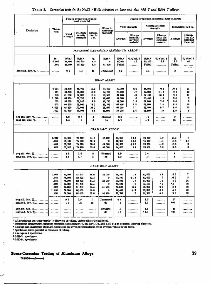
TABLE 3. Corrosion tests in the NaCl+H2O2 solution on bare and clad 75S-T and RS01-T alloys ]
1 All specimens cut transversely to direction of rolling, unless otherwise indicated.2 Specimens (transverse) Japanese extrusion containing 9.1% Zn, 2.2% Cu, and 1.4% Mg as principal alloying elements.3 Average and maximum standard deviations are given in percentages of the average values in the table.4 Specimens taken parallel to direction of rolling.* Average of 2 specimens.6 0.032-in. specimens.7 0.020-in. specimens.
Deviation
max std. dev. % 3
npv.in].
in.0.064
.064
Tensile properties of unex-posed material
•strength
Ultimatetensile
strength
Elonga-tion in2 in.
Stress incorrodingmedium
Tensile properties of material after exposure
Yield strength
Average
JAPANESE EXTRUDED ALUMINUM
Ib/inf81,40081,400
0.9
0/*i.>85,60085,600
0.4
%4.54.5
17
Z6/m.20
61,300
Unstressed
lb/in.>80,400Failed
0.9
R301-T ALLOY
avg std. dev %max std. dev. %
0.064.051.040
4.040.032.025
<.O25.020
59,60060,60061,80064,40059,60060,90062,20058,800
1 02.5
avg std dev. %max std. dev. %
avg std dev. %max std. dev. %
avg std dev %max std. dev. %
0.064.040.040.020
0.064.040.040.032.032
8.020.020
64,90065,10065,20067,300
1 i1.4
69,30071,30071,30069,60069,60074,20074,200
0 61.1
66,70066,80069,30071,70068,80069,000
.70,00066,400
0 61.1
78,50074,80074,80078,900
0 81.7
83,20082,60082,60081,50081,50085,00085,000
0 6. 8
10.510.010.59.09.5
10.010.08.5
4
8
CLAD
14.510.010.012.0
5
8
BARE
14.010.510.512.512.512.012.0
7
15
45,00045,70046,90048,00045,70045,70046,20045,000
Str6SS6cLdo
59,10060,20061,60064,00058,70060,40060,90056,200
2 05.9
75S-T ALLOY
47,7000
49,00050,000
Stresseddo
65,00066,20066,20064,000
1 01.2
75S-T ALLOY
52,0000
53,9000
51,9000
55,800
Unstresseddo
Stresseddo
68,30072,30072,50068,50069,30074,40073,700
0 4. 8
7
1.6
. Changefrom un-corrodedmaterial
ALLOY 2
% of col. 31.2
Ultimate tensilestrength
Average
ib/inS83,100Failed
0.4
Changefrom un-corrodedmaterial
%o/co/.42.9
Elongation in 2 in.
Average
%2.5
Failed
17
Changefrom un-corrodedmaterial
% of col. 644
0.8. 7. 3.6
1.50.82.14.4
66,60067,80069,40070,40067,00068,00069,500 ,65,800
1 i4.2
0.1+1.5+0.1
1.82.6 •1.40.7
. 9
10.09.59.09.09.08.58.08.0
9
18
21201406
15206
+0.1+1.5+1.5
4.9
78,50075,10075,00076,400
0.4. 5
1.4
+1.41.71.60.4
+.3.7
82,00082,00081,60075,10076,60082,30080,200
1.2O q
1.66 4.4
0.0
+.4+.33.2
13.510.510.012.0
4
8
1.4. 7
1.27.96.03.25.6
13.010.08.0
«33.55.02.5
27» 65
287 69
7
+500
75
2476725879
Stress-Corrosion Testing of Aluminum Alloys789520—48 6
79

TABLE 4.—Results
Commercial temper Thick-ness
of corrosion tests
Tensile properties of un-corroded material
Yieldstrength
Ultimatetensile
strength
Elonga-tion in2 in.
in NaCl+H2O2 solution on
Stress incorrodingmedium
the R309-Alloy1
Tensile properties after exposure in NaCl+H2O2 solution
Yield strength
AverageChange
from un-corrodedmaterial
Ultimate tensilestrength
AverageChange
from un-corrodedmaterial
Elongation in 2 in.
AverageChange
from un-corrodedmaterial
BARE MATERIAL
T275T275T275T275...T275T275T275T275
avg std. dev. % 4
max std dev. %
avg std. dev. % __.max std. dev. %
T315T315.T315T315T315.T315T315T315
avg std. dev. %max std. dev. %
avg std. dev. %max std. dev. %
in.0.122.122
2.0662.066
.040
.040
.020
.020
0.126.126.066.066.040.040
2.0202.020
Ib/in*74,10074,10073,40073,40074,40074,40072,70072,700
0.81.2
73,20073,20067,70067,70066,10066,10070,10070,100
0.4.4
Ib/in*82,10082,10079,80079,80080,10080,10080,30080,300
0.61.3
80,10080,10076,60076,60074,30074,30076,50076,500
6.50.8
Percent•11.511.511.011.010.010.010.510.5
45
10.010.09.59.59.59.59.59.5
711
lb\in?0
55,7000
56,1000
55,7000
54,600
Unstressed. . .do
Stresseddo
054,800
050,700
049,400
052,600
Unstressed...do
Stresseddo
Ib/in*72,30072,90074,00075,30069,70070,20073,20072,900
1.12.2
1.31 6
73,30073,70067,70067,80064,90065,30069,400
»71,500
1.42.3
1.22 2
% of col. 32.41.60.8
3+2.46.35.6
+0.7+.3
+0.1+.7
.0+.11.81.21.0
+2.0
lb/in*81,70081,30079,10079,30078,10077,80079,10077,900
0.4.8
. 92.5
80,40080,40076,60076,80073,30073,50075,300
5 76,600
0.5. 8
6
. 8
% of col 40.51.00.9.6
2.52.91.53.0
+0.4+.4
.0+.31.31.11.6
+0.1
Percent
10.011.55.54.05.03.0
1534
3787
9.07.0
10.010.08.08.08.0
« 9.0
58
1945
% of col. 5
9+545605271
1030
+5+51616165
CLAD MATERIAL
T275T275T275T275T275. .T275— , __T275T275.
avg std. dev. %..max std. dev. %.
avg std. dev. %max. std. dev. %
T315T315..T315...T315T315T315T315T315
avg std. dev. %max std. dev. %.
avg std. dev. %.max std. dev. %
0.126.126.065.065
2.0402.040
.020
.020
0.126.126.064.064
2.0402.040
.020
.020
70,70070,70067,40067,40069,20069,20068,00068,000
0.91.5
69,00069,00064,80064,80066,30066,30062,00062,000
0.91.3
78,10078,10074,50074,500 ..75,00075,00075,90075,900
0.37
75,60075,60072,60072,60072,70072,70070,30070,300
0.71.0
11.011,011.511.511.011.09.59.5
46
10.010.09.59.5
11.011.09.09.0
512
052,900
050,600
050,000
050,500
Unstresseddo
Stresseddo
051,900
048,400
050,000
046,600
Unstressed. . .do . . . .
Stresseddo
69,10068,60064,10063,40070,20069,80066, 70068,800
1.52 3
2.23 8
69,20070,40065,00064,90067,00067,40060,10059,700
2.56 6.0
1.7«4.9
2.33.04.95.9
+1.40.91.9
+1.2
+0.3+2.0+0.3+.2
+1.0+1.7
3.03.7
77,80077,00073,00071,70076,40076,00074,70074, 400
0.81.4
1.62.9
75,80075,50072,30072,40073,60073,80069,50070,000
1 86 4.6
1 22.2
0.41.42.03.8
+1.8+1.3
1.62.0
+0.3.1.4.3
+1.2+1.5
1.10.4
11.511.511.011.511.010.09.5
10.0
48
610
10.510.010.510.010.59.06.08.0
811
2245
+4+4
40090
+5
+50
+11+5
5223311
i All specimens taken transversely to direction of rolling. 2 Heat treated from "O" condition at the Bureau. 3 + sign indicates gain.* Average and maximum standard deviations are given in percentages of the average values in the table. «Average of 2 specimens. 6 0.020-in. material.
80 Journal of Research

TABLE 5. Effect of boiling NaCl solution on specimens stressed (three-fourths of yield strength) by bowing :
1 Specimens taken transversely to direction of rolling of sheet except Japanese extruded material.2 Average standard deviations are given in percentages of the average values reported in the table.3 Specimens aged 1 hr at 385° F.4 Specimens from Japanese extrusions contained Zn, Cu, and Mg as principal alloying elements.5 Single specimen; 2 specimens failed in test, 1 in approximately 1 hr, the second in about 1 day.6 Heat treated from " 0 " condition at the Bureau.
Material
75S-T . . .75S-T
avg std. dev. %
24S-T3
avg std. dev. %
Ext.*R303-T275«. .R303-T275
avg std. dev. %--_. -
R303-T315R303-T315 .
avg std. dev. %
R303-T275R303-T2756
avg std. dev. %
R303-T315R303-T315 6 .
avg std. dev. %
Thick-ness
in.0.064.040
0.064
0.064.066.040
0.066.040
0.064.041
0.064.041
Tensile properties ofunexposed material2
Yieldstrength
ib/inJ72,80071,200
0.6
52,800
5.6
86,60073,40074,400
0.9
67, 70066,100
0.3
67,40069,200
0.9
64,80066,300
1.1
Ultimatetensile
strength
Iblin.*83,30081,400
0.3
70,000
1.1
91,10079,80080,100
0.9
76,60074,300
0.5
74,50075,000
0.4
72,60072, 700
0.8
Elonga-tion in
2 in.
Stress incorrodingmedium
Tensile properties after exposure in boiling 6-percent NaCl solution
Yield strength
Average
BARE M A T E R I A L
%10.512
11
14.5
21
101110
5
9.59.5
9
Ib/inl54,70053,400
Stressed
39,600
Stressed
64,90055,00055,800
Stressed
50,70049,600
Stressed
Ib/in.*75,90073,800
1.4
59,400
1.5
5 84,80074,80068,100
1.3
66,50064,800
1.3
CLAD M A T E R I A L
11.511
2
9.511
8
50,50051,900
Stressed
48,60049,700
Stressed
69,30071,800
0.3
65,20071,100
0.4
Changefrom un-corrodedmaterial
% of col. 3+4.3+3.7
+12.5
2.1+1.9 .
8.4
1.82.0
+2.7+3.8
+0.6+7.2
Ultimate tensilestrength
Average
lb/in.2
83,80080,000
1.4
73,900
0.3
88,20079,10074,300
2.1
75,30071,900
1.2
75,80076,900
0.4
72,60075,400
2.0
Changefrom un-corrodedmaterial
%ofcol.4+0.6
1.8
+5.6
3.20.97.2
1.73.2
+1.7+2.5
.0+3.7
Elongation in 2 in.
Average
%99.5
22
13.5
5
8.53
• 3
28
5.05.0
24
10.58.5
6
9.09.0
13
Changefrom un-corrodedmaterial
% of col. 51421
7
157370
4747
923
5;; is
Stress-Corrosion Testing of Aluminum Alloys

jj§ TABLE 6. Tensile properties of transverse specimens of clad 24S- T, R801- T, and clad and bare 75S- T alloys before and after exposure (anodized) in a marine atmosphere
Material
Clad24S-TClad24S-TR301-TR301-TClad 75S-TClad75S-TBare75S-TBare75S-TClad24S-TClad24S-TR301-T.R301-T.. .Clad 75S-TClad75S-TBare75S-TBare75S-TClad24S-TClad24S-TR301-TR301-TBare75S-TBare75S-TClad24S-TClad24S-TR301-T .R301-T.. .Clad75S-TClad75S-TBare75S-TBare75S-T
Clad 24S-T
R301-T
Clad75S-T.____
Bare75S-T
Nominal thick-ness
in.0.064.064.064.064.064.064.064.064.040.040.040.040.040.040.040.040.032.032.032.032.032.032.020.020.020.020.020.020.020.020
[avg std. dev. %[max std dev %
[avg std dev %_[max std. dev.%
} avg std. dev. %[max std. dev. %
javg std. dev. %[max std. dev. %
Exposure
Period *
111111112222222233333344444444
Dura-tion
days919191919191919180808080808080806767676767678989898989898989
Tensile properties of un-corroded material 2
Yieldstrength
Ib/in*41,10041,10059,60059,60063,60063,60072,80072,80043,80043,80061,80061,80064,20064,20071,20071,20043,90043,90059,60059,60066,30066,30044, 70044, 70058,80058,80067,30067,30074,20074,200
1.01.71.32.51.11.40.61.1
Ultimatetensile
strength
Ib/in*64,50064,50066,80066,80077,00077,00083,30083,30066,70066,70069,30069,30077,40077,40081,40081,40065,70065,70068,80068,80079,20079,20063,30063,30066,20066,20078,90078,90085,00085,000
0.81.40.5
.8
.81.70.6
.8
Elonga-tion in2 in.
Percent19.519.510.510.5141410.510.518.518.510.510.512.512.5121219199.59.5
11.511.516168.58.5
12121212
33
814587
15
Appliedstress incorrod-
ingmedium
lb/in*0
31,8000
44,0000
48,7000
54,7000
32,8000
46,4000
47,4000
52,9000
32,4000
45,0000
49,1000
32,8000
44,1000
52,5000
55,200
Tensile properties of exposed material
Yield strength
Average
Z6/m.242,10043,00059,20060,00064,30065,30072,60072, 70043,90046,10061,700
5 59,20064,00063,90071,30071,60045,00045,20059,400
6 57, 80067,10067,80045,300
7 46,60059,60062,40066,500
7 67,50073,40074,600
Standarddevia-tions 3
% of col. 90.8.8
2.51.10.41.40.0
.5
.83.34.0
0.4.5.5
1.40.51.70.9
1.90.8
.81.54.44.00.81.50.3
.6
Changefrom un-corrodedcondition
% of col. 5+2.4+4.6
0.7+.7
+1.1+2.7
0.3.1
+.2+5.3
0.24.20.3
.5+.1+.6
+2.5+3.0
0.33.0
+1.2+2.3+1.3+4.3+1.4+6.1
1.2+0.3
1.1
+0.5
Ultimate tensile strength
Average
Ib/in*64,70059,00068,00066,60078,90079,10083,80083,60066,80066,80068,200
5 68,00077, 70077,60082,10080,60066,50066,10067,300
6 67,10080,30080,30064,70063,50067,60064,10079,600
7 79,60084,80084,400
Standarddevia-tions
% of col. 121.2
413.62.00.8
.3
.3
.7
.6
.5
.22.1
0.3.4.4
4.00.5.8
3.5
0.8.1
1.64.21.2
<9.30.42.10.51.5
Changefrom un-carrodedcondition
% of col. 6
+0.38.5
+1.80.3
+2.5+2.7+0.6+.4+.2+.21.61.9
+0.4+.3+.91.0
+1.2+0.6
2.22.5
+1.4+1.4+2.2+0.3
+2.13.2
0.9+.90.2
.7
Elongation in 2 in.
Average
Percent18.5
10.5
13.513.5111117.516.56
5 4.51212.510.510.56.565.5
6 4.01112.514157.54
11.57 11
108.5
Standarddevia-tions
% of col. 1521
6
445503
68
04
'18259
1082
1807
11
55100
5115
52
Changefrom un-corrodedcondi-tions
% of col. 75
0
44
+5+5
511435740
1313666842584
+9136
125348
1729
1 Period 1, 10/27/44 to 1/26/45; period 2, 1/24/45 to 4/14/45; period 3, 10/27/44 to 1/2/45; period 4, 1/26/45 to 4/25/45.2 The average and maximum standard deviations are given in percentages of the average values of tensile properties.3 See footnote 1, table 2, for methods of computing standard deviations.* This high value of standard deviation indicated nonuniform resistance to corrosion.
5 Single specimen; 2 specimens failed during test.6 2 specimens: 1 specimen failed during test.7 Average of 2 specimens.

TABLE 7. Tensile properties of transverse specimens of the clad 24S-56
T, bare and clad R303-T275 and R303-T315 alloy material before and after exposure forin a marine atmosphere l
Material Nominal thickness
Tensile proi>erties ofuncorroded material
Yieldstrength
Ultimatetensile
strength
Elonga-tion
in 2 in.
Appliedstressin cor-roding
medium
Tensile properties of exposed material
Yield strength
AverageStandard
devia-tions 2
Changefrom un-corrodedmaterial
Ultimate tensile strength
AverageStandard
devia-tions
Changefrom un-corrodedmaterial
Elongation in 2 in.
AverageStandard
devia-tion
Changefrom un-corrodedmaterial
Clad R303-T275 s_.Clad R303-T275 3.
Bare R303-T315. _Bare R303-T315. _
Clad 24S-T.Clad 24S-T.
Clad R303-T275.Clad R303-T275.
Bare R303-T275-* Bare R303-T275-
Clad R303-T315_Clad R303-T315-
Clad 24S-T.Clad 24S-T.
Clad R303-T275-Clad R303-T275_
Bare R303-T275.Bare R303-T275.
Clad 24S-T 2_.
Bare R303-T.
Clad R303-T_
in.0.064.064
.064
.064
.040
.040
.040
.040
.040
.040
.040
.040
.020
.020
.020
.020
.020
.020
Javg std. dev. %[max std. dev. %
javg std. dev. %Imax std. dev. %
Javg std. dev. %(max std. dev. %
Ib/in*68,20068,200
67,70067,700
43,80043,800
66,30066,300
74,40074,400
66,10066,100
44,70044,700
68,00068,000
72,70072.700
1.51.7
0.6.8
1.5
lb/in*75,60075,600
76,60076,600
66,70066,700
73,50073,500
80,10080,100
74,30074,300
63,30063,300
75,90075,900
80,300"80,300
1.31.4
0.5,6
.4
.7
Percent12.512.5
9.59.5
18.518.5
1010
1010
9.59.5
1616
9.59.5
10.510.5
33
Ib/in*0
51,400
050,700
033,500
049,500
056,100
049,600
034,100
050,600
054,800
69,60070,000
67,00069,700
43,40045, 500
66,20066,000
72,00072,600
65,50066,100
43,90045,500
67,00067,500
71,60073,200
Percent1.01.4
0.82.5
0.32.5
0.7
.4
.5
1.0
.51.2
1.10.6
% of col. 3+2.0+2.6
1.0+3.0
0.9+3.9
0.2.5
3.22.4
0.9.0
1.8+1.8
1.50.7
1.5+0.7
76,90076,200
75,60075,900
65,20063,700
73,30073,000
79,20079,000
73,60073,300
62,30062,000
75,80075,800
78,40078,100
Percent0.3.7
.6
.4
1.01.8
0.2.2
1.4
0.5
.4
.4
.6
.6
.3
% of col. 4+1.7+0.8
1.30.9
2.34.5
0.3.7
1.11.4
0.91.3
1.62.0
0.1.1
2.42.7
Percent12.012.0
9.59.0
16.510.5
9.510
9.5
15.514
3.53.5
Percent55
820
2743
55
2529
136
311
107
1451
% of col. 544
05
1143
50
313
6767
1 Specimens exposed 4/26/45 to 6/21/45 without surface preparation except degreasing.2 Average and maximum standard deviations are given in percentages of average values given in table.3 Heat treated from " O " condition at this Bureau.

The average tensile strength of the clad 24S-Tmaterial, 0.064 in. thick, was reduced from 64,500lb/in.2 for the unexposed material to 59,000 lb/in.2
for material exposed under stress. The tensilestrength of exposed but unstressed material wasnot significantly reduced. The large value of thestandard deviation, 13.6 percent, for the clad24S-T alloy in this gage indicates that the speci-mens were not uniformly resistant to the combinedaction of stress and corrosion. The ultimate ten-sile strengths of the clad 24S-T material in thethinner gages were not appreciably decreased bycorrosion or the combined action of stress andcorrosion. The elongation of the 0.032-in. thickmaterial was reduced from 19 to 6 percent as theresult of exposure; the elongations of the 0.040-and 0.020-in. specimens were not appreciablyreduced as the result of stress and exposure in themarine atmosphere. No intercrystalline corrosionwas found in the clad 24S-T or 75S-T alloy speci-mens after they had been exposed in the marineatmosphere.
The ultimate tensile strength of the 0.064-in.R301-T material was not appreciably changed asthe result of stress and exposure. For the 0.020-in. thicknesses, the tensile strength of the stressedspecimens was reduced from 66,200 to 64,100lb/in.2, and the elongation was reduced from 8.5 to4 percent. Two of the 0.040-in. specimens, andone of the 0.032-in. specimens failed during theexposure period. One 0.040-in. specimen failedafter 38 days and the other after 80 days of expo-sure; the 0.032-in. specimen failed after 67 days.As indicated above, these specimens were exposedunder stresses equal to about three-fourths of theyield strength; the stresses amounted to 46,400lb/in.2 for the 0.040-in. specimens and 45,000lb/in.2 for the 0.032-in. specimens.
Because there had been no failures of specimensof the other materials in exposure periods as longas 91 days, additional sets of R301-T specimensin three gages were exposed without surface pro-tection by anodizing or other]means, in the marineatmospheric exposure^racks in November of 1946.Specimens were unstressed and stressed to three-fourths of the yield strength. Two of the 0.025-in.-thick specimens failed after approximately 18days of exposure. Intercrystalline-corrosion andstress-corrosion cracks, as shown in figures 11 and
12, were found penetrating into the core materialfrom the unclad surfaces of the specimens. Thefractured surfaces of these specimens were verysimilar to those found in the specimens that hadfailed in the earlier tests. Although no evidenceof stress-corrosion cracking had been found onmetallographic examination of the earlier speci-mens, it seems possible that all of the failures thatoccurred in the marine atmosphere were due tointercrystalline corrosion penetrating into the corematerial from the cut surfaces.
The fact that there was no appreciable loss intensile strength of the R301-T material afterexposure in the sodium chloride-hydrogen perox-ide solution may be explained as follows: Theclad layer may be considered to be the anode of agalvanic cell, the core material the cathode, thecorroding solution the electrolyte, and the ex-ternal circuit the material itself. In such a cellthe clad material may be preferentially destroyedwith no appreciable attack on the core material.In atmospheric exposure the same type of celldevelops as long as any drops of moisture, col-lected at the cut edges, are sufficiently largeto connect the core material and clad layers.However, if the drops of moisture are confined tothe core material alone, a new type of cell isset up. The galvanic cells cease to be macroscopicand become microscopic. The material adjacentto the grain boundaries in this type of heat-treated alloy is believed to be impoverished incopper and has been shown to have a more neg-ative electrochemical solution potential than thematerial within the grain or crystal [13]. Thematerial at or adjacent to the grain boundarybecomes the anode, the body of the crystalbecomes the cathode, and the grain-boundarymaterial goes into solution, giving rise to thewell-known intercrystalline type of corrosion.
(c) R303-T and Clad 24S-T Materials
Data for the R303 alloys, clad and bare, inthe — T275 and — T315 tempers and for the clad24S-T alloy are given in table 7 and are showngraphically in figure 13, These specimens wereexposed for 56 days in the marine atmospherewithout surface protection by anodizing or othermeans.
84 Journal of Research

The data indicate that the R303 material,bare and clad, in both the —T275 and —T315conditions, was generally at least as resistant tocorrosion and to the combined action of stressand corrosion as the clad 24S-T material in thesame gages.
No intercrystalline corrosion was found ineither of these alloys on metallographic examina-tion after they had been exposed in the marineatmosphere.
V. Summary
The results of marine atmospheric weatherexposure and laboratory stress-corrosion testsdescribed in this paper indicate that:
1. Commercially flat bare 24S-T aluminumalloy sheet, aged 4 hr or longer at 375° F, was notsusceptible to stress-corrosion cracking in eitherlaboratory tests in the NaCl+H2O2 solution orin marine atmospheric exposure tests. Specimensaged for this period or longer were at least asresistant to the combined action of stress and corro-sion as the commercially heat-treated but unagedmaterial exposed under the same conditions.
2. Clad and bare specimens of the 75S-Talloy and of the clad and bare R303 alloy in the—T275 and — T315 conditions were found, afterexposure periods of 60 to 90 days to be generallyas resistant to corrosion or the combined actionof stress and corrosion as the clad 24S-T alloyin the same gages.
3. The maximum loss in tensile strength of anyset of specimens of the R301-T alloy immersed for24 hr in the NaCl+H2O2 solution was 2.6 percentand was attributed to the pitting type of corrosion.The tensile strength of the 0.064-in. material wasnot significantly reduced as the result of exposureunder stress in the marine atmosphere. How-ever, five specimens of this alloy in 0.025-,0.032-, and 0.040-in. gages exposed under stressequal to three-fourths of the yield strength failedafter exposure in the marine atmosphere for periodsranging from 18 to 80 days. Intercrystallinecorrosion and stress-corrosion cracks, penetratinginto the core material from the cut edges, werefound in two of these failed specimens.
It should be noted that the failed specimenswere }2 in. wide. The failure of specimens of this
width does not indicate that wide sheets of thismaterial, exposed under stress in a marine atmos-phere, will fail as the result of intercrystallinecorrosion penetrating into the core material fromthe cut edges.
4. The results indicated that stress may appre-ciably increase corrosion damage to certain alloysof the duralumin type and to certain aluminumalloys containing appreciable quantities of zincthat are continually immersed for 24 hr in theNaCl+H2O2 solution.
5. The data indicated that a boiling 6-percentNaCl solution may produce stress-corrosion crack-ing in alloys containing appreciable amounts ofzinc. The 24S-T alloy, artificially aged so as tobe susceptible to severe intercrystalline corrosionin the NaCl+H2O2 solution, was not stress-cracked in the boiling chloride solution.
6. The results indicate that there was generallygood agreement between weather exposure andlaboratory tests, except for the R301-T alloy.The contradictory results obtained in the twomedia on this material indicate the desirability ofchecking the results obtained on a clad materialcontinuously immersed in the NaCl+H2O2 solu-tion with those obtained on stressed specimensexposed to the weather.
The assistance of Houston Babb, Thomas P.Royston, Jr., and Richard C. Rohan, and the co-operation of Fred M. Reinhart and the late WillardH. Mutchler of this Bureau; of Harold E. Francis,formerly of this Bureau; and of Lts. C. A. Snavelyand M. Franklin of the Naval Air Station, Hamp-ton Roads, Va., in this investigation is gratefullyacknowledged. Data on the Japanese extrusionwere obtained in cooperation with the NationalAdvisory Committee for Aeronautics. Their per-mission to use these data is appreciated.
VI. References
[1] A. Wilm, Metallurgie 8, 225 (1911).[2] E. H. Dix, Jr., NACA Tech. Note 259 (1927).[3] Private communication from E. H. Dix, Jr., Alumi-
num Co. of America, to National Bureau of Stand-ards.
[4] P. P. Mozley, J. Aeron. Sci. 10, 180 (1943).[5] J. D. Grogan and R. J. Pleasance, J. Inst. Metals 64,
57 (1939).
Stress-Corrosion Testing of Aluminum Alloys 85

[6] G. Forrest, Metal Ind. (London) 56, 229 (1940). [11] G. F. Sager, R. H. Brown, and R. B. Mears, Am. Soc.[7] H. S. Rawdon, NACA Tech. Note 284 (April 1928). Symposium on Stress Corrosion Cracking of Metals,[8] R. B. Mears, R. H. Brown, and E. H. Dix, Jr., Am. p. 255, ASTM and AIME (1944).
Symposium on Stress Corrosion Cracking of Metals, [12] R L L H H e s s i n g ' a n d H . E. Francis, J. Re-p. 329, ASTM aod AIME (1944). search NBS 38, 465 (1947) RP1788.
[9] Army-Navy Aeronautical Specification A^-QQ-H-186a, Heat treatment of aluminum alloys, process [13] E. H. Dix, Jr., Trans. Inst. Metals Div. Am. Inst.for, paragraph E-7 (b). Mining Metal Engrs. 137, 11 (1940).
[10] Private communication from F. P. Somers, Bureau ofAeronautics, Navy Department, Washington. WASHINGTON, August 20, 1947.
o
86 Journal of Research


![Advanced Cast Aluminum Alloys - DTIC · Wrought 7055 aluminum alloy is the highest strength conventionally processed, commercially available, wrought aluminum alloy [2]. The yield](https://img.pdfslide.us/doc/110x75/5f33c89d21254a014f5911cb/advanced-cast-aluminum-alloys-dtic-wrought-7055-aluminum-alloy-is-the-highest.jpg)