Embed Size (px)
Citation preview

7/23/2019 STRESS AND BURST PRESSURE DETERMINATION OF SHRINK FITTED COMPOUND CYLINDRICAL PRESSURE VESSEL
http://slidepdf.com/reader/full/stress-and-burst-pressure-determination-of-shrink-fitted-compound-cylindrical 1/78
STRESS AND BURST PRESSURE DETERMINATION
OF SHRINK FITTED COMPOUND CYLINDRICAL
PRESSURE VESSEL
Thesis is submitted in thepartial fulfillment of therequirement for thedegreeof
MASTER OF MECHANICAL ENGINEERING
By :
HARERAM LOHAR
Examination Roll No. : M4MEC13-24
Registration No. : 117131 of 2011-2012
Department of Mechanical Engineering
Jadavpur University
Under the Guidance of :
DR. SUSENJIT SARKAR
&
DR. SAMAR CHANDRA MONDAL
Faculty of Engineering and Technology
Department of Mechanical Engineering
Jadavpur University
Kolkata – 700 032
May, 2013

7/23/2019 STRESS AND BURST PRESSURE DETERMINATION OF SHRINK FITTED COMPOUND CYLINDRICAL PRESSURE VESSEL
http://slidepdf.com/reader/full/stress-and-burst-pressure-determination-of-shrink-fitted-compound-cylindrical 2/78
ii
FACULTY OF ENGINEERING AND TECHNOLOGY
DEPARTMENT OF MECHANICAL ENGINEERING
JADAVPUR UNIVERSITY
KOLKATA – 700 032
DECLARATION OF ORIGINALITY AND
COMPLIANCE OF ACADEMIC ETHICS
I hereby declare that this thesis contains literature survey and original research work by the
undersigned candidate, as part of his Master of Mechanical Engineering (MachineDesign)
studies.
All information in this document havebeen obtained and presented in accordancewith academic rules
and ethical conduct.
I also declare that, as required by these rules and conduct, I have fully cited and referred all
material and results that arenot original to this work.
Name : Hareram Lohar
Examination Roll Number :
Registration Number :
Thesis Title : Stress Analysis and Burst Pressure
Determination Of Shrink fitted
Compound Cylindrical Pressure Vessel
Signature :
Date :

7/23/2019 STRESS AND BURST PRESSURE DETERMINATION OF SHRINK FITTED COMPOUND CYLINDRICAL PRESSURE VESSEL
http://slidepdf.com/reader/full/stress-and-burst-pressure-determination-of-shrink-fitted-compound-cylindrical 3/78
iii
FACULTY OF ENGINEERING AND TECHNOLOGY
JADAVPUR UNIVERSITY
CERTIFICATE OF APPROVAL *
This foregoing thesis is hereby approved as a credible study of an engineering subject carried
out and presented in a manner satisfactory to warrant its acceptanceas a prerequisiteto the
degreefor which it has been submitted. It is understood that by this approval the undersigned do
not endorse or approve any statement made, opinion expressed or conclusion drawn therein but
approvethethesis only for thepurposefor which it has been submitted.
Committee Signature_______________________________
on Date_______________________________
Final Examination for Seal
Evaluation of theThesis
Signature_________________________________
Date_________________________________
Seal
* Only in casethethesis is approved

7/23/2019 STRESS AND BURST PRESSURE DETERMINATION OF SHRINK FITTED COMPOUND CYLINDRICAL PRESSURE VESSEL
http://slidepdf.com/reader/full/stress-and-burst-pressure-determination-of-shrink-fitted-compound-cylindrical 4/78
iv
FACULTY OF ENGINEERING AND TECHNOLOGY
JADAVPUR UNIVERSITY
CERTIFICATE OF SUPERVISION
We hereby recommend that the thesis presented under our supervision by Mr. HareramLohar
entitled “STRESS AND BURST PRESSURE DETERMINATION OF SHRINK FITTED
COMPOUND CYLINDRICAL PRESSURE VESSEL” beaccepted in partial fulfillment of the
requirements for thedegreeof Master of Mechanical Engineering.
1)
________________________________
2)
________________________________
(Signatures of theThesis Adviser)
Countersigned by : Date:
Seal :
_______________________________________________________
( Signatureof theHead of theDepartment, Mechanical Engineering )
Date:
Seal :
______________________________________________________
( Signatureof theDean of Faculty of Engineering and Technology )
Date:
Seal

7/23/2019 STRESS AND BURST PRESSURE DETERMINATION OF SHRINK FITTED COMPOUND CYLINDRICAL PRESSURE VESSEL
http://slidepdf.com/reader/full/stress-and-burst-pressure-determination-of-shrink-fitted-compound-cylindrical 5/78
v
ACKNOWLEDGEMENT
In every work, there have been so many heads behind the screen without whomthe
work might not reach that far as it should be. Very likely, I can remember many names who helped
me a lot during my project work. In this regard I pay my well gratitude to themwhosesupport
and cooperation inspired memorally in my good and bad days during thecourseof work.
At thevery outset, I acknowledgethegenerous and arduous assistanceand inspiration
provided by my guide, Dr. Susenjit Sarkar and my co. guideDr. Samar Chandra Mondal. Without
whosekind attention and tremendous support my thesis could not havereached this stage in proper
way. Words of thanks fall short to express my gratitude to them in proper dimensions for
their kind cooperation and methodical guidance in theentirespan of theprocess.
I would like to convey my regards to the Laboratory-in-Charge of ‘MachineElements
Laboratory’ and all other Professors who helped meduring thework.
I am greatly indebted to my friends and seniors of machine design specialization who
havehelped meconceiving certain ideas related to my project and also gavemesubstantial support in
thesoftwarepart.
Lastly, it is likely to mention that without the suggestions and hospitality of my family
and well wishers, it could havebeen difficult to carry out theproject work and completethethesis in
time. Hence, I would liketo express my gratitudeto themtoo.
Date:
______________________________________
( HARERAM LOHAR )
Examination Roll No.: M4MEC13-24
Registration No. : 117131 of 2011-2012

7/23/2019 STRESS AND BURST PRESSURE DETERMINATION OF SHRINK FITTED COMPOUND CYLINDRICAL PRESSURE VESSEL
http://slidepdf.com/reader/full/stress-and-burst-pressure-determination-of-shrink-fitted-compound-cylindrical 6/78
vi
This thesis is solely dedicated to my
P arents

7/23/2019 STRESS AND BURST PRESSURE DETERMINATION OF SHRINK FITTED COMPOUND CYLINDRICAL PRESSURE VESSEL
http://slidepdf.com/reader/full/stress-and-burst-pressure-determination-of-shrink-fitted-compound-cylindrical 7/78
vii
CONTENTS
SUBJECTS PAGENO.
DECLARATION ii
CERTIFICATE OF APPROVAL iii
CERTIFICATE OF SUPERVISION iv
ACKNOWLEDGEMENT v
DEDICATION vi
CONTENTS vii
LIST OF FIGURES ix
LIST OF TABLES xi
NOMENCLATURE xii
1. INTRODUCTION 1-11
1.1
Fundamental Idea of Pressure Vessel 2
1.2 Compound Cylinder 2
1.3 Burst Pressure 5
1.4 FEM Analysis 6
1.5
History and Context of the Present Work 8
1.6
Objective and Methodology 9
1.7 Summary of the Thesis 10
2. LITARATURE REVIEW 12-19
2.1 Compound Cylinder 13
2.2 Burst Pressure 16
2.3
FEM Analysis 18
3. MATHEMATICAL FORMULATION 20-43
3.1
Stress Analysis 21-38
3.1.1
Stress Analysis of Single Layer Cylinder 21
3.1.2 Stress Analysis of Two Layer Compound Cylinder 26

7/23/2019 STRESS AND BURST PRESSURE DETERMINATION OF SHRINK FITTED COMPOUND CYLINDRICAL PRESSURE VESSEL
http://slidepdf.com/reader/full/stress-and-burst-pressure-determination-of-shrink-fitted-compound-cylindrical 8/78
viii
3.1.3
Stress Analysis of Three Layer Compound Cylinder 29
3.2
Burst Pressure Determination 39-43
3.2.1
Burst Pressure of Single Layer Compound Cylinder 39
3.2.2
Burst Pressure of Two Layer Compound Cylinder 41
3.2.3
Burst Pressure of Three Layer Compound Cylinder 42
4. ANALYTICAL MODEL 44-49
4.1 Stress Analysis 45-47
4.1.1 Stress Analysis of Single Layer Cylinder 45
4.1.2
Stress Analysis of Two Layer Compound Cylinder 45
4.1.3 stress analysis of three layer compound cylinder 46
4.2
Burst Pressure Determination 47-49
4.2.1
Burst Pressure of Single Layer 47
4.2.2
Burst Pressure of Two Layer Compound Cylinder 47
4.2.3
Burst Pressure of Three Layer Compound Cylinder 49
5. FEM ANALYSIS 50-56
5.1
Stress Analysis 51-
5.1.1
Stress Analysis of Single Layer Cylinder 51
5.1.2
Stress Analysis of Two Layer Compound Cylinder 51
5.1.3 Stress Analysis of Three Layer Compound Cylinder 53
5.2 Burst Pressure Determination 53-56
5.2.1 Burst Pressure of Single Layer 53
5.2.2 Burst Pressure of Two Layer Compound Cylinder 54
5.2.3
Burst Pressure of Three Layer Compound Cylinder 55
6. DISCUSSION 57-58
7. CONCLUSION 59-61
8. REFERENCES 62-64

7/23/2019 STRESS AND BURST PRESSURE DETERMINATION OF SHRINK FITTED COMPOUND CYLINDRICAL PRESSURE VESSEL
http://slidepdf.com/reader/full/stress-and-burst-pressure-determination-of-shrink-fitted-compound-cylindrical 9/78
ix
LIST OF FIGURES
Fig. 1.1 Compound Cylinder
Fig. 1.2 Internal Pressure Vs Hoop Stress Distribution
Fig. 1.3 Two Layer Compound CylinderFig. 1.4 Three Layer Compound Cylinder
Fig. 3.1 Stress in a Thick Wall Cylinder
Fig. 3.2 A Three Layer Compound Cylinder Vessel
Fig. 3.3 Radial and Hoop Stress Distribution in Three Separate Cylinders of Three Layer
Compound Cylinder
Fig. 3.4 Interference between Cylinder 1 & 2 of Three Layer Compound Cylinder
Fig. 3.5 Interference between Cylinder 2 & 3 of Three Layer Compound Cylinder
Fig. 3.6 Superposition of Hoop Stress due toi
P & Residual Stress due to12s
P in Cylinder
1 of Three Layer Compound Cylinder
Fig. 3.7 Superposition of Hoop Stress due toiP & Residual Stress due to
12sP &23sP in
Cylinder 2 of Three Layer Compound Cylinder
Fig. 3.8 Superposition of Hoop Stress due toiP & Residual Stress due to
23sP in Cylinder
3 of Three Layer Compound Cylinder
Fig. 3.9 Superposition of Hoop Stress due toiP & Residual Stress due to
12sP &23sP in
all Cylinder of Three Layer Compound Cylinder
Fig. 5.1 Maximum Principal Stress due to 35 Mpa Internal Pressure in Thick Cylinder inANSYS
Fig. 5.2 Maximum Principal Stress due to 35 Mpa Internal Pressure in Two Layer
Compound Cylinder in ANSYS
Fig. 5.3 Maximum Principal Stress due to 35 Mpa Internal Pressure in Inner Tube in
ANSYS of Two Layer Compound Cylinder
Fig. 5.4 Maximum Principal Stress due to 35 Mpa Internal Pressure in Jacket in ANSYS
of Two Layer Compound Cylinder
Fig. 5.5 Maximum Principal Stress due to 35 Mpa Internal Pressure in Three Layer
Compound Cylinder in ANSYS
Fig. 5.6 Maximum Principal Stress due to Elastic Break-Down Pressure of Single
Cylinder Layer in ANSYS
Fig. 5.7 Maximum Principal Stress due to Burst Pressure of Single Layer Cylinder in
ANSYS

7/23/2019 STRESS AND BURST PRESSURE DETERMINATION OF SHRINK FITTED COMPOUND CYLINDRICAL PRESSURE VESSEL
http://slidepdf.com/reader/full/stress-and-burst-pressure-determination-of-shrink-fitted-compound-cylindrical 10/78
x
Fig. 5.8 Maximum Principal Stress due to Burst Pressure of Two Layer Cylinder in
ANSYS
Fig. 5.9 Maximum Principal Stress due to Elastic Break-Down Pressure of Three Layer
Compound Cylinder in ANSYS
Fig.5.10 Maximum Principal Stress due to Burst Pressure of Three Layer Compound
Cylinder in ANSYS

7/23/2019 STRESS AND BURST PRESSURE DETERMINATION OF SHRINK FITTED COMPOUND CYLINDRICAL PRESSURE VESSEL
http://slidepdf.com/reader/full/stress-and-burst-pressure-determination-of-shrink-fitted-compound-cylindrical 11/78
xi
LIST OF TABLES
Table 4.1 Stresses due to Internal Pressure of Two Layer Compound Cylinder
Table 4.2 Stresses due to Shrinkage Pressure for Inner Tube & Jacket of Two Layer
Compound CylinderTable 4.3 Resultant Stresses of Two Layer Compound Cylinder
Table 4.4 Data for Modeling Stress Analysis due to internal pressure 35 Mpa of Three
Layer Compound Cylinder
Table 5.1 Data for Modeling Stress Analysis in ANSYS for Thick Single Layer Cylinder
Table 5.2 Data for Modeling Stress Analysis in ANSYS for of Two Layer Compound
Cylinder
Table 5.3 Data for Modeling in ANSYS for Stress Analysis of Three Layer Compound
Cylinder
Table 5.4 Data for Modeling Elastic Break-down Pressure and Burst Pressure of Single
Layer Cylinder
Table 5.5 Data for Modeling Burst Pressure in ANSYS of Two Layer Compound Cylinder
Table 5.6 Data for Modeling Elastic-Breakdown Pressure in ANSYS of Three Layer
Compound Cylinder
Table 5.7 Data for Modeling Burst pressure in ANSYS of Three Layer Compound Cylinder

7/23/2019 STRESS AND BURST PRESSURE DETERMINATION OF SHRINK FITTED COMPOUND CYLINDRICAL PRESSURE VESSEL
http://slidepdf.com/reader/full/stress-and-burst-pressure-determination-of-shrink-fitted-compound-cylindrical 12/78
xii
NOMENCLATURE
SINGLE LAYER CYLINDER
a Inner radius of Cylinder
b Outer radius of Cylinder
wP Working Pressure on the Inner Surface
t Hoop Stress in Cylinder
r Radial stress in the cylinder
a Axial Stress in Cylinder
Poisson’s ratio
t Hoop Strain in Cylinder
r Radial Strain in Cylinder
a Axial Strain in Cylinder
TWO LAYER COMPOUND CYLINDER
j
Increase in inner diameter of jacket
c Decrease in outer diameter of cylinder
= total Interference
t j Tangential Strain for Jacket
t c Tangential Strain for Inner Cylinder
1 D Inner Diameter of the Inner Cylinder
2 D Outer Diameter of the Inner Cylinder & Outer Diameter of the Jacket
3 D Outer Diameter of the Jacket
iP Internal Pressure
P Shrinkage Pressure between Inner Cylinder and Jacket
t Hoop Stress in Cylinder
THREE LAYER COMOUND CYLINDER
iP Internal pressure acting on the cylinder 1

7/23/2019 STRESS AND BURST PRESSURE DETERMINATION OF SHRINK FITTED COMPOUND CYLINDRICAL PRESSURE VESSEL
http://slidepdf.com/reader/full/stress-and-burst-pressure-determination-of-shrink-fitted-compound-cylindrical 13/78
xiii
Hoop stress in the cylinder
r Radial stress in the cylinder
1r Inner radius of cylinder 1
2r Outer radius of cylinder 1 and Inner radius of cylinder 2
3r Outer radius of cylinder 2 and Inner radius of cylinder 3
4r Outer radius of cylinder 3
12sP Contact pressure between cylinder 1 and 2
23sP Contact pressure between cylinder 2 and 3
12 Total interference at the contact between cylinder 1 and 2
23 Total interference at the contact between cylinder 2 and 3
Poisson’s ratio
1t 2
1
r r
2t 3
2
r
r
3t 4
3
r
r

7/23/2019 STRESS AND BURST PRESSURE DETERMINATION OF SHRINK FITTED COMPOUND CYLINDRICAL PRESSURE VESSEL
http://slidepdf.com/reader/full/stress-and-burst-pressure-determination-of-shrink-fitted-compound-cylindrical 14/78
xiv
ABSTRACT
PressureVessels, storepressurized fluids in different phase, pressureand temperature
conditions with great importanceand safety precautions, arewidely used in household
and industrial purpose. Multilayer pressurevessel is designed to work under high-
pressure condition. This thesis introduces the stress analysis and burst pressure
calculation of a multi-layer shrink fitted pressurevessel. In theshrink-fitting problems,
considering long hollow cylinders, the plane strain hypothesis can be regarded as
more natural. Generally hoops stress distribution is non-linear and sharply reduced
toward theouter surface. By shrink fitting concentric shells towards theinner shells are
placed in residual compression so that theinitial compressive hoop stress must be
relieved by internal pressurebefore hoop tensile stress are developed. Therefore the
maximumhoop stress will bereduced, resulting moreburst pressure. Theanalytical
results of stress distribution and burst pressureis calculated and validated by ANSYS
Workbench results.

7/23/2019 STRESS AND BURST PRESSURE DETERMINATION OF SHRINK FITTED COMPOUND CYLINDRICAL PRESSURE VESSEL
http://slidepdf.com/reader/full/stress-and-burst-pressure-determination-of-shrink-fitted-compound-cylindrical 15/78
Chapter – 1
Introduction
This chapter named as Introduction provides a general
introduction to the entire work. It gives an overall idea of
pressure vessel and burst pressure context of the
present work, objective and planning of the work and
brief summary of the entire thesis
sequentially.

7/23/2019 STRESS AND BURST PRESSURE DETERMINATION OF SHRINK FITTED COMPOUND CYLINDRICAL PRESSURE VESSEL
http://slidepdf.com/reader/full/stress-and-burst-pressure-determination-of-shrink-fitted-compound-cylindrical 16/78
Introduction
2
1.1
INTRODUCTION TO PRESSURE VESSELS
Pressure vessels are used to contain fluid (liquid or gas) under pressure and
temperature. The pressure acting on vessel may sometimes be from outside also. So the
pressure situation may be internal or external.
Vessels which carry fluid under pressure and temperature are also subjected to the
action of steady or dynamic support loading, piping reactions and thermal shock which require an
overall knowledge of the stresses imposed by these conditions.
Pressure vessels commonly have the form of spheres, cylinders, ellipsoids, or some
composite of these. In practice, vessels are usually composed of two or more pressure containing
shells together with flange, rings and fastening devices for connecting and securing mating parts.
The main difference of thick shell pressure vessel from the thin shell is the
stresses developed over the section thickness cannot be assumed to be uniformly distributed
(as in the thin shells have). Only the axial stress is found to be uniformly distributed over
the wall thickness. Both the tangential and radial stresses are dependent on the radius of the
geometry under consideration.
1.2
COMPOUND CYLINDER
One of the common method of pre-stressing is to use compound (or composite) cylinders
- two or more cylinders which are assembled with an interference fit. The analysis which follows
is elastic since the method does not generally involve yielding - and may be applied to sleeves
pressed onto shafts, etc.
Two open cylinders only are considered. They are shown in exaggerated fashion both
before assembly (individually completely free), and after assembly and pressurising (ie. after all
load components have been applied). The bore of the outer cylinder and the outside diameter of
the inner cylinder are made to the same nominal common diameter Dc - however there is a known
small diametral interference, Δ << Dc. The cylinders are then assembled concentrically using heat
or force, and loaded by pressures internal and external to the assembly, pi and po respectively.

7/23/2019 STRESS AND BURST PRESSURE DETERMINATION OF SHRINK FITTED COMPOUND CYLINDRICAL PRESSURE VESSEL
http://slidepdf.com/reader/full/stress-and-burst-pressure-determination-of-shrink-fitted-compound-cylindrical 17/78
Introduction
3
Before safety of either cylinder can be addressed, the common interface pressure pc must
be known. But the problem is statically indeterminate since statics reveals only that if pcexists as a
contact pressure internal to the outer cylinder, then the inner cylinder is pressurised externally by
the same amount. Geometric compatibility and the cylinders' constitutive laws must be invoked.
If the common diameter Dc increases by δi measured on the inner cylinder as sketched, and by
δo measured.
On the outer the compatibility requires that:
Δ = δo - δi
Fig.1.1 Compound Cylinder
In thick walled cylinders subjected to internal pressure only, it can be seen from the
equation of the hoop stress that the maximum stresses occur at the inside radius and this can be
given by:
This means that as pi increases σt may exceed yield stress even when p i < σyield .
Furthermore, it can be shown that for large internal pressures in thick walled cylinders the wall
thickness is required to be very large. This is shown schematically in figure
Fig.1.2 Internal pressure vs. hoop stress distribution

7/23/2019 STRESS AND BURST PRESSURE DETERMINATION OF SHRINK FITTED COMPOUND CYLINDRICAL PRESSURE VESSEL
http://slidepdf.com/reader/full/stress-and-burst-pressure-determination-of-shrink-fitted-compound-cylindrical 18/78
Introduction
4
This means that the material near the outer edge of the cylinder is not effectively used
since the stresses near the outer edge gradually reduce.
In order to make thick-walled cylinders that resist elastically large internal pressure
and make effective use of material at the outer portion of the cylinder the following
methods of pre-stressing are used:
• Shrinking a hollow cylinder over the main cylinder. (Compound cylinders)
• Multilayered or laminated cylinders.
• Autofrettage or self hooping.
An outer cylinder (jacket) with the internal diameter slightly smaller than the outer
diameter of the main cylinder is heated and fitted onto the main cylinder. When the
assembly cools down to room temperature, a compound cylinder is obtained. In this process the
main cylinder is subjected to an external pressure leading to radial compressive stresses at the
interface (Pc) as shown in figure 3.
The outer cylinder is subjected to an internal pressure leading to tensile circumferential
stresses at the interface (Pc) as shown in figure 4. Under these conditions as the internal pressure
increases, the compression in the internal cylinder is first released and then only the cylinder
begins to act in tension.
Fig.1.3 Two layer compound cylinder

7/23/2019 STRESS AND BURST PRESSURE DETERMINATION OF SHRINK FITTED COMPOUND CYLINDRICAL PRESSURE VESSEL
http://slidepdf.com/reader/full/stress-and-burst-pressure-determination-of-shrink-fitted-compound-cylindrical 19/78
Introduction
5
Fig.1.4 Three layer compound cylinder
1.3
BURST PRESSURE
On subjecting a thick-walled vessel to increasing internal pressure, stresses are induced in
the shell which are maximum at the bore, as predicted by the various criteria for failure based
upon theory of elasticity. Contrary what might be expected, failure of a shell of ductile material
usually does not begin at the fibers along the bore but the fibers along the outside surface of the
shell. On stressing beyond the yield point, most metals pass through a region of plastic flow in
which elongation progresses without an increase in resisting stress. This condition is firstly
reached in the inner part of the cylinder. However, the strain of the inner zone is limited by the
outer zone, which is not stressed beyond the yield point; thus the inner fibers are incapable of
rapture. The inner fibers of an over-stressed vessel often show evidence of slip where failure
began but halted because of the restraint offered by the outer fibers. The inner fibers therefore
prevented from failing, provided that the outer fibers offer sufficient restraint. There is no such
protection of the outer fibers by the inner fibers.
Manning has discussed the rapture of thick-walled cylinders of ductile metal. The
pressure necessary for the yield point of the metal fibers in the bore to be reached is known as the
“elastic-breakdown” pressure. At this pressure the maximum fiber stress is the tangential stress at

7/23/2019 STRESS AND BURST PRESSURE DETERMINATION OF SHRINK FITTED COMPOUND CYLINDRICAL PRESSURE VESSEL
http://slidepdf.com/reader/full/stress-and-burst-pressure-determination-of-shrink-fitted-compound-cylindrical 20/78
Introduction
6
the inner surface. The radial stress also has its maximum value at the bore, and this stress is equal
to the internal pressure. As the pressure is raised, the region of plastic flow, termed overstrain
moves radially outward and causes the tangential stress to decrease in the inner layers and to
increase rapidly in the outer layers. Progressive increase in pressure moves the elasto-plastic
interference radially outward until the interference reaches the outer radius and no elastic zone
remains. At this situation maximum hoop stress is at the outer surface. Manning has reported that
from the beginning of overstrain for a vessel in which the outer diameter to inside diameter ratio
was 2:1 and the pressure was 12750 psi, the tangential stress at the inner radius was 21000 psi and
at the outer radius 8000 psi. for the same vessel. for the same pressure vessel with 100%
overstrain (plastic-elastic interface at r o) at a pressure of 27,620 psi, the tangential stress at bore
was 16000 psi, and at the outer surface 34000 psi. thus it is apparent that the tangential stress
distribution is totally different in the 100% plastic state than in the complete elastic state. On the
other hand, the radial stress pattern has similar shapes for the complete elastic and complete
plastic state.
When failure occurs in the shell of a ductile metal as the result of progressive increase in stress, it
usually follows the path of a continuous helix from the outer surface onward.
Prager and Hodge have defined the internal pressure in a cylindrical vessel that is
required to place the elasto-plastic interference on the outer surface of the vessel. this is the
pressure required to place all the vessel wall beyond the yield point. In deriving the relationship it
is necessary to establish the condition under which plastic flow is initiated.
1.4 FEM ANALYSIS
The Finite element Analysis (FEA) method, originally introduced by Turner (1956), is a
powerful computational technique for approximate solutions to a variety of “real-world”
engineering problems having complex domains subjected to general boundary conditions. FEA
has become an essential step in the design or modeling of physical phenomenon in various
engineering disciplines. A physical phenomenon usually occurs in a continuum of matter (solid,

7/23/2019 STRESS AND BURST PRESSURE DETERMINATION OF SHRINK FITTED COMPOUND CYLINDRICAL PRESSURE VESSEL
http://slidepdf.com/reader/full/stress-and-burst-pressure-determination-of-shrink-fitted-compound-cylindrical 21/78
Introduction
7
liquid, gas) involving several field variables. The field variables vary point to point, these
processing infinite solutions in the domain.
In this method, the body or structure is divided into on equivalent system of smaller
bodies or units. The assemblage of such a units that represents the original bodies. Instead of
solving the problem for the entire body in one operation, the solutions are formulated for each
constituents unit and combine the solution for the original body or structure. This approach is
known as going from part to whole.
The method can be symmetrically programmed to accommodate such complex and
difficult problems as non-homogeneous materials, non-linear stress-strain behavior and
complicated boundary conditions.
The basic theory of Finite Element Method is representation of a body or a structure by an
assemblage of small sub-divisions called finite elements. These elements are considered inter-
connected at joints, which are nodes or nodal points. The elements are super-imposed on to a co-
ordinate guided system, where nodal points are preferred with respect to a co-ordinate system.
The position and elastic properties of elements are defined by the matrices, so that the
displacement of each elements can be related to the forces on the element. Finally a composite
matrix of the system of every elements of the structure is are formed which relates to the
displacements of the nodal point of each element to the external force on the structure. Once the
displacement field is determined, the strains can be evaluated by using the strain-displacement
relationship and finally, the stress can be evaluated by stress-strain relations.
The finite element analysis method requires the following steps:
Discretization of the domain into a finite number of sub domains (elements).
Selection of interpolation function (the value of field variables at specific points
refers to as nodes).
Development of the element matrix for the sub domain (elements).
Assembly of the element matrices for each sub domain to obtain the global
matrix for the entire domain.

7/23/2019 STRESS AND BURST PRESSURE DETERMINATION OF SHRINK FITTED COMPOUND CYLINDRICAL PRESSURE VESSEL
http://slidepdf.com/reader/full/stress-and-burst-pressure-determination-of-shrink-fitted-compound-cylindrical 22/78
Introduction
8
Imposition of the boundary conditions.
Solution of equations.
Additional computation (if desired).
1.5
HISTORY AND CONTEXT OF THE PRESENT WORK
Pressure vessel is an age old term, with the advancement of modern civilization
the use of pressure vessel also increased. It is used in everywhere from household goods to large
scale industries with same importance. The basic conception was invented long ago in about
15th
century related to the history of canons, but its significance to the practical life started
increasing since 19th century when Lamè proposed the eq.(s) for thick walled cylinder.
Relative to this plasticity also attracted the researcher’s attention in 19th century when
Tresca published a preliminary account of experiments on punching and extrusion, which
led him to state that a metal yielded plastically when the maximum shear stress attained a critical
value.
The idea of determining burst pressure of a compound pressure vessel is a very new
approach. A full understanding of the behavior of a pressurized thick walled cylinder was not
possible without an understanding of the post-yield behavior of metals under a biaxial stress
state. This was provided by the maximum shear stress theory of ‘‘failure’’ as proposed by
Tresca. Saint-Venant published an analysis of the plastic deformation of a pressurized
thick-walled cylinder which introduced the concept of Autofrettage.
Many researchers have focused on methods to extend lifetimes of vessels. Majzoobi et
al. have proposed the optimization of bi-metal compound cylinders and minimized the
weight of compound cylinder for a specific pressure [6]. The variables were shrinkage radius
and shrinkage tolerance. Patil S. A. has introduced optimum design of two layer compound
cylinder and optimized intermediate, outer diameter and shrinkage tolerance to get minimum
volume of two layer compound cylinders [7-8]. Niranjan et at.have proposed the optimization of
shell thickness in multilayer pressure vessels and also investigated the effect of no. of shell on

7/23/2019 STRESS AND BURST PRESSURE DETERMINATION OF SHRINK FITTED COMPOUND CYLINDRICAL PRESSURE VESSEL
http://slidepdf.com/reader/full/stress-and-burst-pressure-determination-of-shrink-fitted-compound-cylindrical 23/78
Introduction
9
maximum hoops stress[4]. At the same time Ayub A. Miraje and Sunil A. Patil have proposed the
optimization of three layer shrink fitted cylinder for uniform stress distribution[5].
To incorporate this new movement into the determination of burst pressure of a
compound pressure vessel this entire work is carried out, hope we will have some fruitful results.
1.6 OBJECTIVE AND METHODOLOGY
In a sentence Increased Strength -to- weight Ratio and Extended Burst Pressure are the
main objectives of the optimal Autofrettaging. The process of compounding itself ensure
uniform stress distribution and increased burst pressure. The process involves cost so optimum
uniform distribution is very important and also give better result.
The objective of this present work is to formulate the stress distribution equations
in the pressurize condition for the each layer then to find out the shrinkage pressure in between
the two layer by equating the inner side hoop stress of the each layer. From this shrinkage
pressure the shrinkage interference in between two layers will be determined. As the busting of a
compound cylinder occur at the outer layer, so the pressure required at the inner side of the outer
layer to bust the outer layer have to calculate. Then have to equate this pressure with the sum of
shrinkage pressure and the interference pressure to get the burst pressure of the whole compound
cylinder.
The problem is defined now and to evaluate we need to plan our methodology as
follows :
1)
Mathematically formulate the problem for the stress distribution using Lame’s equations
for the each layer.
2)
After finding hoop stresses at all the radii, the principle of superposition is applied, i.e.
the various stresses are then combined algebraically to produce the resultant hoop stresses
in the compound cylinder subjected to both shrinkage pressures and internal pressure.

7/23/2019 STRESS AND BURST PRESSURE DETERMINATION OF SHRINK FITTED COMPOUND CYLINDRICAL PRESSURE VESSEL
http://slidepdf.com/reader/full/stress-and-burst-pressure-determination-of-shrink-fitted-compound-cylindrical 24/78
Introduction
10
3) For optimum stress distribution it is considered that the resultant stress in the inner
surface of each layer is equal and the optimum contact shrinkage pressure and the
optimum shrinkage interferences are calculated.
4)
For formulating the burst pressure of compound cylinder it is considered that the outer
layer will burst first and the whole compound cylinder.
5)
After mathematical deduction is done, an analytical model is deduced by taking a certain
problem.
6)
After that we validated our results by using FEM software ANSYS Workbench version
v11.
7)
Finally we compared results, analyzed and got to some conclusions.
The entire work can be divided into three phases they are:
I. Mathematical Formulation (step 1 – step 4, chapter 3),
II. Analytical Model (step 5, chapter 4), and
III. FEM Analysis and Validation (step 6 – step 7, chapter 5).
1.7
SUMMARY OF THE THESIS
The thesis is based on the work discussed above. It constitutes of mainly five chapters.
The first chapter named as Introduction provides a general introduction to the entire
work. It gives an overall idea of pressure vessel, compound cylinder, burst pressure and FEM
Analysis, context of the present work objective and planning of the work and brief summary of
the entire thesis sequentially.
The second chapter is titled as Literature Review, where different works of several
researchers up to present time are surveyed, historical background is nurtured and context of the
present work are planned.

7/23/2019 STRESS AND BURST PRESSURE DETERMINATION OF SHRINK FITTED COMPOUND CYLINDRICAL PRESSURE VESSEL
http://slidepdf.com/reader/full/stress-and-burst-pressure-determination-of-shrink-fitted-compound-cylindrical 25/78
Introduction
11
The third chapter named as Mathematical Formulation gives the through deduction of
stress distributions for single layer thick cylinder, two layer compound cylinder and three layer
compound cylinder. Also the burst pressure of single layer thick cylinder, two layer compound
cylinder and three layer compound cylinder is determined at the end of the chapter.
The fourth chapter named as Analytical Model where a certain problem is considered
and stress analysis and burst pressure determination is done for corresponding single layer thick
cylinder, two layer compound cylinder and three layer compound cylinder.
The fifth chapter named as FEM Analysis where a finite element analysis is done using
ANSYS Workbench v11 software and the stresses and burst pressure of single layer thick
cylinder, two layer compound cylinder and three layer compound cylinder is validated.
The sixth chapter is the most important chapter named as Discussion. Here the results of
analytical model and FEM analysis are compared and error is also computed and shown that the
errors are in acceptable limits.
The seventh chapter is the general Conclusion, where merits and demerits of the present
work are dealt and the readers of the thesis are directed towards the future scope of work or
further continuation or modification of the present work.

7/23/2019 STRESS AND BURST PRESSURE DETERMINATION OF SHRINK FITTED COMPOUND CYLINDRICAL PRESSURE VESSEL
http://slidepdf.com/reader/full/stress-and-burst-pressure-determination-of-shrink-fitted-compound-cylindrical 26/78
Chapter – 2
Literature Review
This chapter is titled as Literature Review, where different
works of several researchers upto present time are surveyed,
historical background is nurtured and context of the present
work are planned.
7/23/2019 STRESS AND BURST PRESSURE DETERMINATION OF SHRINK FITTED COMPOUND CYLINDRICAL PRESSURE VESSEL
http://slidepdf.com/reader/full/stress-and-burst-pressure-determination-of-shrink-fitted-compound-cylindrical 27/78
Literature Review
13
It is customary and quite meaningful to introduce any subject through its historical
development; hence the review work may start mentioning some earlier studies in the area of
proposed work constructing the context of the same.
The history of high-pressure technology began in the early 14th century. The earliest
pioneer in the field of Autofrettage was a German monk named Berthold Schwarz, who invented
the first known “cannon”. A canon is a thick walled pressure vessel open at one end, intended to
contain the high pressure and temperature gaseous products of an explosive detonation while they
accelerate projectile through its muzzle. For several centuries, the gun was the only significant
application of high pressure in which the pressure is contained. Gradually as the time passed
away, range of high-pressure technology got broad. Then it covers pipes, boilers, reactors etc.
2.1. COMPOUND CYLINDER
Due to the ever-increasing industrial demand for axisymmetric pressure vessels which
have had wide applications in chemical, nuclear, fluid transmitting plants, power plants, gas
storages [1,2] and military equipments, the attention of designers has been concentrated on this
particular branch of engineering. On the other hand, the increasingly scarcity of materials and
higher costs have led researchers not to confine themselves to the customary elastic regime but
attracted their attention to the elastic-plastic along with optimization approach which offer more
efficient use of materials. Basically there are two basic different elastic-plastic techniques to
increase the pressure capacity of thick-walled cylinders. In the first, the cylinder is subjected to
internal pressure so that its wall becomes partially plastic. The pressure is then released and the
resulting residual stresses increase the pressure capacity of the cylinder in the next loading stage.
This procedure is called 'autofrettage' [3,4]. The analysis of residual stresses and deformation in
an autofrettaged thick-walled cylinder has been given by Chen [5] and Franklin and Morrison [6].
In the second technique, two or more cylinders are shrunk into each other with different
diametral interferences to form a compound cylinder. The shrinkage produces a residual stress

7/23/2019 STRESS AND BURST PRESSURE DETERMINATION OF SHRINK FITTED COMPOUND CYLINDRICAL PRESSURE VESSEL
http://slidepdf.com/reader/full/stress-and-burst-pressure-determination-of-shrink-fitted-compound-cylindrical 28/78
Literature Review
14
distribution within the walls of the cylinders, which improves the cylinder behavior against the
working pressure.
Many researchers contributed in the field of Compound Cylinder. Some of them
discussed various ways to find out stress distribution in pressure vessels considering the pressure
condition and sometimes thermal loading as well.
The basic governing mathematical formulation for stress generation in thick walled
pressure vessel was proposed by Lamè (1795-1870) and his colleagues in 1833 [1].
Gun designers during the mid-1800s recognised the poor utilisation of material (uneven
stress distribution) within thick-walled guns, applying a practical upper limit on the range of wall
ratios that could be used. It was realised that if some inwards force could be applied to a barrel,
the effect of poor material utilisation could be mitigated. To this end, barrels were “hooped” to
pre-compress the inner surface of the barrel – for example, William Armstrong [2] assembled
compound cylinders from wrought iron tubes. Additionally, it was recognised by Rodman [3] that
if the cooling of cast cannon were controlled, the sequence of crystallisation from liquid could
influence the residual stress distribution and hardness of the tube material at the bore.
The relationships which follow in compound cylinder were first presented by H.L. Cox in
1936. The theory as developed is based upon the assumption that the maximum combined stresses
(hoop-pressure stress plus hoop-shrinkage stress) existing at the inner surface of each of the
several shells will attain a certain identical value. It is assumed that both the internal and external
diameters are known and that the number of shells is to be a minimum. It is also assumed that the
combined cylinder is fabricated by shrinking on each successive shell from the inside outwards
and that after each shell is shrunk on, the outside diameter is machined to size before the next
cylinder is shrunk on to the inner shell or shells.
In 2005 G.H. Majzoobi, A. Ghomi proposed Optimisation of two layer compound
pressure cylinders [13].The purpose of this paper was optimization of the weight of compound

7/23/2019 STRESS AND BURST PRESSURE DETERMINATION OF SHRINK FITTED COMPOUND CYLINDRICAL PRESSURE VESSEL
http://slidepdf.com/reader/full/stress-and-burst-pressure-determination-of-shrink-fitted-compound-cylindrical 29/78
Literature Review
15
cylinder for a specific pressure where the variables were shrinkage radius and shrinkage tolerance.
SEQ technique for optimization, the finite element code ANSYS for numerical simulation is
employed to predict the optimized conditions. They investigated that the weight of a compound
cylinder could reduce by 60% with respect to a single steel cylinder. The reduction is more
significant at higher working pressures. While the reduction of weight is negligible for k<2.5, it
increases markedly for 2.5<k<5.5. The stress at the internal radii of the outer and inner cylinders
become equal to the yield stresses of the materials used for compound cylinders.
In 2011 investigated on optimization of shell thickness in multilayer pressure vessel and
study on effect of number of shells on maximum hoop stress [11]. In this paper, optimization of
thickness of each layer in multilayer vessel was carried out by Genetic Algorithm and then stress
distribution was analyzed under optimum shrink-fit condition. The fatigue life was calculated for
shrink-fit multilayer vessel. Thickness of each vessel was considered as design variable and
objective function was maximum hoop stress through-out the thickness at the given working
pressure. Multilayer vessel was assumed to be constructed by insertion of different vessels with
zero interference and zero clearance such that interface pressure at the mating surfaces was equal
to the pressure generated at the same surface due to interference fit. Effect of number of shells on
the maximum value of hoop stress was analyzed. Apart from this, effect of overall thickness of
pressure vessel on the effectiveness of multi-layering was brought into focus. Stress distribution
and fatigue life for the obtained thickness of each vessel from Genetic Algorithm was nearer to
that obtained from Lagrange’s multiplier method.
In 2011he (Niranjan Kumar et al.) extended his work to optimum autofrettage pressure
and shrink-fit combination for minimum stress in multilayer pressure vessel. In this paper,
optimization of thickness of each layer in multilayer vessel was carried out by Genetic Algorithm
and then stress distribution was analyzed under optimum shrink-fit condition. The fatigue life was
calculated for shrink-fit multilayer vessel. Thickness of each vessel was considered as design

7/23/2019 STRESS AND BURST PRESSURE DETERMINATION OF SHRINK FITTED COMPOUND CYLINDRICAL PRESSURE VESSEL
http://slidepdf.com/reader/full/stress-and-burst-pressure-determination-of-shrink-fitted-compound-cylindrical 30/78
Literature Review
16
variable and objective function was maximum hoop stress through-out the thickness at the given
working pressure.
At the same time (2012) Ayub A. Miraje and Sunil A. Patil introduced the optimum
design for minimization of thickness of three-layer shrink-fitted compound cylinder to get equal
maximum hoop stresses in all the cylinders [12]. In this paper effort is made to find optimum
minimum thicknesses of three cylinders so that material volume is reduced and hoop stress is
equal in all the cylinders. The analytical results of optimum design calculated with computer
programming are validated in comparison with Finite Element Analysis in ANSYS Workbench.
2.2. BURST PRESSURE
Many researchers contributed in the field of burst pressure.
In 2009 burst tests and volume expansions of vehicle toroidal LPG fuel tanks was
proposed by kisioglu [18]. This study addressed the prediction of the burst pressures and
permanent volume expansions of the vehicle toroidal LPG fuel tanks using both experimental and
finite element analysis (FEA) approaches. The experimental burst test investigations were carried
out hydrostatically in which the cylinders were internally pressurized with water. The LPG tanks
were subjected to incremental internal uniform pressure in the FEA modeling. 2D nonlinear plane
models were developed and evaluated under non-uniform and axisysmmetric boundary
conditions. For the analysis, the required actual shell properties including weld zone and thickness
variations were investigated. Therefore, the results of the burst pressures and volume expansions
were predicted and compared to experimental one.
Kaptan and Kisioglu determined the BP of the cylindrical LPG fuel tanks using both
experimental and finite element method _FEM_ approaches in 2007 [19]. The primary aim of
this study was to determine the burst pressures (BP) and the failure locations of LPG cylinders
whose service pressure (SP) and test pressures (TP) are known. The purpose of this work was to
investigate the BP and failure locations of LPG fuel tanks using both experimental burst tests and

7/23/2019 STRESS AND BURST PRESSURE DETERMINATION OF SHRINK FITTED COMPOUND CYLINDRICAL PRESSURE VESSEL
http://slidepdf.com/reader/full/stress-and-burst-pressure-determination-of-shrink-fitted-compound-cylindrical 31/78
Literature Review
17
FEA. To predict the BP and the failure location using computer modeling, the actual shell and
weld zone material properties (MPs) including thickness variations were investigated from the
LPG tanks. These properties were used in the FEA to approximate the BP values obtained
experimentally. Two different types of two-dimensional (2D) nonlinear FEA models, plane and
shell, were developed under axi-symmetric boundary conditions.
Aksoley et al. compared the BP of the LPG tank, used for home-kitchen applications,
employing the experimental and FEM techniques in 2008 [20].
Mirzaei analyzed the failure of the exploded cylinders containing and transporting the
hydrogen gas using the analytical methods in 2008 [21]. This paper reported the major activities
carried out during the failure analysis of an exploded cylinder containing hydrogen. The general
cracking pattern of the cylinder, the fractographic features, and the stress analysis results were all
indicative of an internal gaseous detonation. Accordingly, several specific characteristics of
detonation-driven fracture of closed-end cylindrical tubes were identified. These characteristics
were analyzed through detailed examinations of the fracture surfaces, cracking patterns, and
dynamic stress analysis of the cylinder using a transient analytical model. Based on the size and
location of special markings found on the shear lips, and using the time duration of flexural
waves, the crack growth increments and speed were computed. Consequently, the basic features
of the gaseous detonation and the composition of the original gas mixture were identified. The
results indicated that the detonation of a low-pressure oxygen-rich mixture of hydrogen and
oxygen was the cause of this failure. The presence of oxygen was attributed to an improper
usageof an oxygen cylinder for hydrogen storage.
Xue et al. determined the influence of geometrical parameters on the burst pressure of a
cylindrical shell intersection using analytical method in 2010 [22]. In this paper, the FEA
simulation procedure was validated by comparison with the results from experiments employing
test vessels, which were hydraulically pressurized to burst. Based on the agreement between the
numerical and experimental results, a parametric analysis was here carried out to determine the

7/23/2019 STRESS AND BURST PRESSURE DETERMINATION OF SHRINK FITTED COMPOUND CYLINDRICAL PRESSURE VESSEL
http://slidepdf.com/reader/full/stress-and-burst-pressure-determination-of-shrink-fitted-compound-cylindrical 32/78
Literature Review
18
influence of geometric parameters (diameter ratio, thickness ratio, and diameter to thickness ratio)
on the burst pressure of radial intersections. An empirical formula for this pressure was then
developed based on the parametric analysis results.
Finite element analysis of burst pressure of composite hydrogen storage vessels by P. Xu
a, J.Y. Zheng b, P.F. Liu b in 2009 [23]. In this research, a 3D parametric finite element model
was proposed to predict the damage evolution and failure strength of the composite hydrogen
storage vessels, in which a solution algorithm was proposed to investigate the progressive damage
and failure properties of composite structures with increasing internal pressure. The maximum
stress, Hoffman, Tsai–Hill and Tsai–Wu failure criteria which awere employed respectively to
determine the failure properties of composite vessels were incorporated into the numerical method
as individual subroutines. The birth-to-death element technique in the finite element analysis was
used to describe the mechanical properties of carbon fiber/epoxy composite elements. Parametric
studies in terms of the effects of different failure criteria were performed and the calculated
failure strengths of composite vessels were also compared with the experimental results.
Research on bursting pressure formula of mild steel pressure vessel by ZHENG Chuan-
xiang, LEI Shao-hui in 2006 [24]. Of several formulas for calculating bursting pressure of mild
steel vessel, the Faupel formula is the most famous one. In fact, Faupel formula is conservative in
calculating mild steel pressure. Based on hundreds of bursting experiments on mild steel pressure
vessels such as Q235(Gr.D), 20R(1020) and, after statistically analyzing data on bursting
pressure, it was found that the Faupel formula had some errors in calculation. The authors derived
a more approximate modified formula from the data, which proved more general after examining
the data on other mild steel pressure vessels with different diameters and shell thickness.
2.3. FEM ANALYSIS
The Finite element Analysis (FEA) method, originally introduced by Turner (1956), is a
powerful computational technique for approximate solutions to a variety of “real-world”
engineering problems having complex domains subjected to general boundary conditions. FEA

7/23/2019 STRESS AND BURST PRESSURE DETERMINATION OF SHRINK FITTED COMPOUND CYLINDRICAL PRESSURE VESSEL
http://slidepdf.com/reader/full/stress-and-burst-pressure-determination-of-shrink-fitted-compound-cylindrical 33/78
Literature Review
19
has become an essential step in the design or modeling of physical phenomenon in various
engineering disciplines.
The Finite Element Method and Application in Engineering Using ANSYS by Erdogan
Madenci and Ibrahim Guven [25]. In this book mathematical formulation of finite element
method and a variety of analysis tutorials are given.
ANSYS Workbench Tutorial (ANSYS Release 10) by Kent L. Lawrence [26]. In this
book a variety of tutorials are given which help to understand the ANSYS Workbench Software.

7/23/2019 STRESS AND BURST PRESSURE DETERMINATION OF SHRINK FITTED COMPOUND CYLINDRICAL PRESSURE VESSEL
http://slidepdf.com/reader/full/stress-and-burst-pressure-determination-of-shrink-fitted-compound-cylindrical 34/78
Chapter-3
Mathematical Formulation
This chapter named as Mathematical Formulation gives the through deduction of stress
distributions for single layer thick cylinder, two layer compound cylinder and three layer
compound cylinder. Also the burst pressure of single layer thick cylinder, two layer compound
cylinder and three layer compound cylinder is determined at the end of the chapter.

7/23/2019 STRESS AND BURST PRESSURE DETERMINATION OF SHRINK FITTED COMPOUND CYLINDRICAL PRESSURE VESSEL
http://slidepdf.com/reader/full/stress-and-burst-pressure-determination-of-shrink-fitted-compound-cylindrical 35/78
Mathematical Formulation
21
3.1 STRESS ANALYSIS
3.1.1
STRESS ANALYSIS OF SINGLE LAYER CYLINDER
From the geometry given below, let ‘r’ be any radius, ‘dr’ is any elementary
radius after r, ‘l’ is any length in axial direction. Now, ifr and
t denote the radial and
tangential stresses,
Fig.3.1 Stress in a thick walled cylinder
then from the consideration of equilibrium under vertical forces :
. . . . 2 . . .sin 02
r r r t
d d l r dr d l rd i dr
For small values of ‘ d ’, sin2
d
2
d ; and the above equation becomes :
. . 0r r t dr rd ld dr l d
neglecting the product of small quantities, this implies :
0r r t dr rd dr
7/23/2019 STRESS AND BURST PRESSURE DETERMINATION OF SHRINK FITTED COMPOUND CYLINDRICAL PRESSURE VESSEL
http://slidepdf.com/reader/full/stress-and-burst-pressure-determination-of-shrink-fitted-compound-cylindrical 36/78
Mathematical Formulation
22
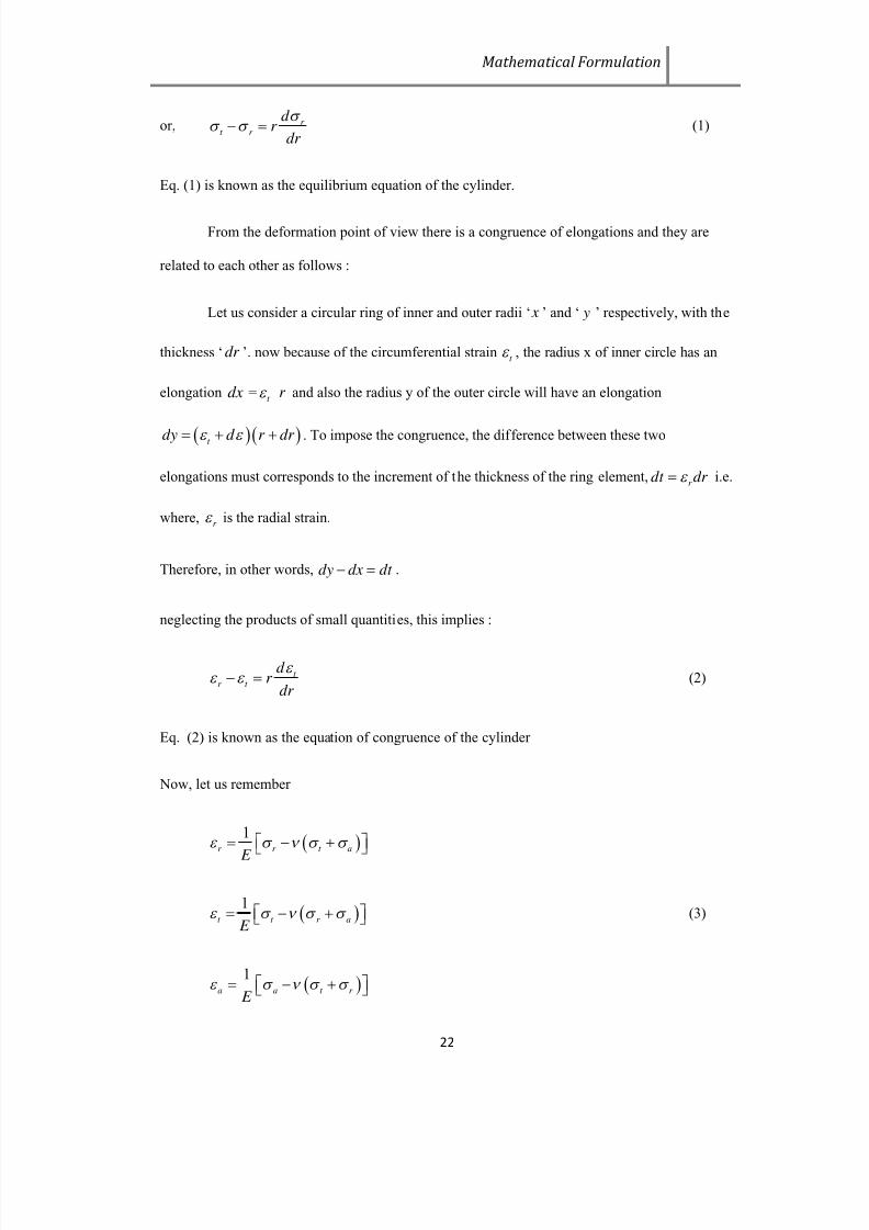
or, r t r
d r
dr
(1)
Eq. (1) is known as the equilibrium equation of the cylinder.
From the deformation point of view there is a congruence of elongations and they are
related to each other as follows :
Let us consider a circular ring of inner and outer radii ‘ x ’ and ‘ y ’ respectively, with the
thickness ‘ dr ’. now because of the circumferential straint
, the radius x of inner circle has an
elongation dx =t r and also the radius y of the outer circle will have an elongation
t dy d r dr . To impose the congruence, the difference between these two
elongations must corresponds to the increment of the thickness of the ring element,r dt dr i.e.
where,r is the radial strain.
Therefore, in other words, dy dx dt .
neglecting the products of small quantities, this implies :
t r t
d r
dr
(2)
Eq. (2) is known as the equation of congruence of the cylinder
Now, let us remember
1
r r t a
E
1
t t r a E
(3)
1
a a t r E

7/23/2019 STRESS AND BURST PRESSURE DETERMINATION OF SHRINK FITTED COMPOUND CYLINDRICAL PRESSURE VESSEL
http://slidepdf.com/reader/full/stress-and-burst-pressure-determination-of-shrink-fitted-compound-cylindrical 37/78
Mathematical Formulation
23
Where, E is the Modulus of Elasticity and ‘ν’ is the Poisson’s ratio of the thick cylinder material.
Now applying eq. (3), eq. (2) becomes :
0ar r t r t r d d d r r r
dr dr dr
This can also be written as :
1 0t ar r t r
d d d d r r r r
dr dr dr dr
Comparing this eq. with eq. (1) we find :
t ar d d d
dr dr dr
Now, if we differentiate 1
a a t r E
1a a t r d d d d
dr E dr dr dr
Now, comparing last two eq. (s) we have :
21a ad d
dr E dr
As thea
is uniform throughout radial direction, i.e. transverse section remains plane, and hence
the axial strain ‘a ’ is constant, therefore :
0t r d d
dr dr
Now, if we differentiate eq. (1) w.r.t ‘r’, we have :
7/23/2019 STRESS AND BURST PRESSURE DETERMINATION OF SHRINK FITTED COMPOUND CYLINDRICAL PRESSURE VESSEL
http://slidepdf.com/reader/full/stress-and-burst-pressure-determination-of-shrink-fitted-compound-cylindrical 38/78
Mathematical Formulation
24
2
20t ar r
d d d d r
dr dr dr dr
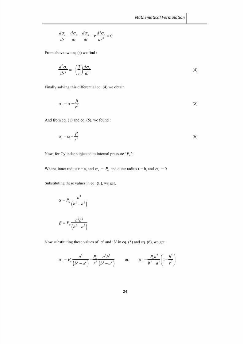
From above two eq.(s) we find :
2
2
3r r
d d
dr r dr
(4)
Finally solving this differential eq. (4) we obtain
2r r
(5)
And from eq. (1) and eq. (5), we found :
2t r
(6)
Now, for Cylinder subjected to internal pressure ‘wP ’;
Where, inner radius r = a, andr =
wP and outer radius r = b, andr = 0
Substituting these values in eq. (E), we get,
2
2 2w
aP
b a
2 2
2 2w
a bP
b a
Now substituting these values of ‘α’ and ‘β’ in eq. (5) and eq. (6), we get :
2 2 2
22 2 2 2
w
r w
Pa a bP
r b a b a
or,
2 2
2 2 21w
r
P a b
b a r
7/23/2019 STRESS AND BURST PRESSURE DETERMINATION OF SHRINK FITTED COMPOUND CYLINDRICAL PRESSURE VESSEL
http://slidepdf.com/reader/full/stress-and-burst-pressure-determination-of-shrink-fitted-compound-cylindrical 39/78
Mathematical Formulation
25
2 2 2
22 2 2 2
w
t w
Pa a bP
r b a b a
or,
2 2
2 2 21w
t
P a b
b a r
As far asa is concern, it can be calculated considering the equilibrium of the forces along
axial direction i.e. mainly the thrust on the heads. It will come out to be constant
2 2 2
w aP a b a or,
2
2 2
wa
P a
b a
To summarize, the three principal stresses are as follows :
2 2
2 2 2
1w
r
P a b
b a r
2 2
2 2 21w
t
P a b
b a r
(7)
2
2 2
wa
P a
b a
The equations shown in eq. (7) are known as Lamè’s equations.
The Lamè’s equations are based on two basic assumptions. 1) Cylinder material is Brittle
in nature, and 2) Cylinder has closed end conditions.
The entire analysis in this thesis is based on Lamè’s equations and assumptions. Now we
will see what happens if we pre stress the same cylinder with an enough high amplitude internal
pressure. One thing should be cleared, that though Lamè’s equations and assumptions deals with
brittle material, but in practice it has been seen that ductile materials are also responds well in
overloading Autofrettaging as those material passes through a strain – hardening process in the
post elastic region.

7/23/2019 STRESS AND BURST PRESSURE DETERMINATION OF SHRINK FITTED COMPOUND CYLINDRICAL PRESSURE VESSEL
http://slidepdf.com/reader/full/stress-and-burst-pressure-determination-of-shrink-fitted-compound-cylindrical 40/78
Mathematical Formulation
26
Now we will discuss about the formulation of stress distribution of the Autofrettaged
thick cylinder. Most of the assumptions and calculations are same for both considering and not
considering Bauschinger Effect. Only the difference comes when we formulate the unloading
stress distribution. For both the cases, for vessels to be subjected to internal pressure it is required
to pre-stress the vessel in the same direction as the working pressure do, but in a enough larger
magnitude. This will develop a compressive residual stress upon release.
From the elementary study on pressure vessel it is clear that mainly Circumferential or
Tangential Stress is more prone to failure, and hence it is taken for designing pressure vessels
with suitable factor of safety.
3.1.2
STRESS ANALYSIS OF TWO LAYER COMPOUND CYLINDER
Let us consider a compound cylinder, consisting of a cylinder and a jacket as shown in
fig. The inner diameter of the jacket is slightly smaller than the outer diameter of the cylinder.
When the jacket is heated, it expands sufficiently to move over the cylinder. As the jacket cools, it
tends to contract onto the inner cylinder, which induces residual compressive stresses. There is a
shrinkage pressure p between the cylinder and jacket. The pressure p tends to contract the cylinder
and expand the jacket .
3.1.2.1 TOTAL INTERFERENCE
Let,
j increase in inner diameter of jacket
c decrease in outer diameter of cylinder
The tangential strain (t
) for the jacket is given by,
t j change in circumference / original circumference
2
j
D
(8)
The tangential strain t c for the cylinder is given by,

7/23/2019 STRESS AND BURST PRESSURE DETERMINATION OF SHRINK FITTED COMPOUND CYLINDRICAL PRESSURE VESSEL
http://slidepdf.com/reader/full/stress-and-burst-pressure-determination-of-shrink-fitted-compound-cylindrical 41/78
Mathematical Formulation
27
t c
2
c
D
(9)
Also, 1
t t r j E (10)
From (1), 2 j t r
D
E
(11)
Where,
2 2
3 2
2 2
3 2
i
t
P D D
D D
and
r iP
Substituting the above values in Eq. (11),
2 2
3 22
2 2
3 2
i j
D D D P
E D D
Similarly, t c
1t r
E
From (2), 2c t r
D
E (12)
Where,
2 2
2 1
2 2
2 1
i
t
P D D
D D
and
r iP
Substituting the above values in Eq. (12),
2 2
2 12
2 2
2 1
ic
D D D P
E D D
The negative sign indicates contraction. Neglecting the positive and negative signs and
considering only magnitudes, the total deformation ( ) is given by,
2 2 2
2 3 12
2 2 2 2
3 2 2 1
2i
D D DPD
E D D D D
(13)
3.1.2.2 STRESS DUE TO INTERNAL PRESSURE
Stress due to internal pressure at1
D

7/23/2019 STRESS AND BURST PRESSURE DETERMINATION OF SHRINK FITTED COMPOUND CYLINDRICAL PRESSURE VESSEL
http://slidepdf.com/reader/full/stress-and-burst-pressure-determination-of-shrink-fitted-compound-cylindrical 42/78
Mathematical Formulation
28
1
2 2
1 3
22 213 1
1i
t atD
P D D
D D D
(14)
At2
D
2
2 2
1 3
22 223 1
1i
t atD
PD D
D D D
(15)
At3 D
3
2
1
2 2
3 1
2 i
t atD
PD
D D
(16)
3.1.2.3
STRESS DUE TO SHRINKAGE PRESSURE
3.1.2.3.1 JACKET
Let P is the shrinkage pressure
So stress due to shrinkage pressure P at2 D of the jacket
2
22
32
22 223 2
1t atD
DPD
D D D
(17)
At 3 D
3
2
2
2 2
3 2
2t atD
PD
D D
(18)
3.1.2.3.2
INNER TUBE
So stress due to shrinkage pressure P at1 D of inner tube
1
2
2
2 2
2 1
2t atD
PD
D D
(19)
At2
D
2
2 2
2 1
22 222 1
1t atD
PD D
D D D
(20)

7/23/2019 STRESS AND BURST PRESSURE DETERMINATION OF SHRINK FITTED COMPOUND CYLINDRICAL PRESSURE VESSEL
http://slidepdf.com/reader/full/stress-and-burst-pressure-determination-of-shrink-fitted-compound-cylindrical 43/78
Mathematical Formulation
29
3.1.2.4 SHRINKAGE PRESSURE
Equating stresses at the inner surfaces of tube and jacket. From equation (14), (15), (19) & (17).
2 2 2 2 22 21 3 1 3 32 2
2 2 22 2 2 2 2 2 2 21 2 23 1 2 1 3 1 3 2
21 1 1i iPD D P D D DPD PD
D D D D D D D D D D D
Or,2 2 2 2 2 22 2
3 1 3 2 3 21 2
2 2 2 2 2 2 2 2 2
3 1 2 3 1 2 1 3 2
2/
i
D D D D D D D DP P
D D D D D D D D D
(21)
3.1.3
STRESS ANALYSIS OF THREE LAYER COMPOUND CYLINDER
Consider three cylinders have same material. The method of solution for compound
cylinders constructed from similar materials is to break the problem down into four separate
effects:
i) shrinkage pressure12sP only on the cylinder 1
ii) shrinkage pressure12s
P and23s
P only on the cylinder 2
iii) shrinkage pressure23s
P only on the cylinder 3
iv) internal pressureiP only on the complete cylinder
Thus for each condition the hoop and radial stresses at any radius can be evaluated.

7/23/2019 STRESS AND BURST PRESSURE DETERMINATION OF SHRINK FITTED COMPOUND CYLINDRICAL PRESSURE VESSEL
http://slidepdf.com/reader/full/stress-and-burst-pressure-determination-of-shrink-fitted-compound-cylindrical 44/78
Mathematical Formulation
30
Fig.3.2 A three layer compound pressure vessel
Fig.3.3 Radial and hoop stress distribution in three separate cylinders
Fig.3.4 Interference between cylinder 1 & 2 Fig.3.5 Interference between 2 & 3

7/23/2019 STRESS AND BURST PRESSURE DETERMINATION OF SHRINK FITTED COMPOUND CYLINDRICAL PRESSURE VESSEL
http://slidepdf.com/reader/full/stress-and-burst-pressure-determination-of-shrink-fitted-compound-cylindrical 45/78
Mathematical Formulation
31
3.1.3.1 Radial and Hoop stress in Cylinder 1
Ifi
P i.e. no internal pressure, radial stress in cylinder 1 is given by using Lame’s equation
2 2
2 1
12 2 2 22 1
1r s
r r P
r r r
(22)
r is maximum at outer radius2r of cylinder 1 . Using equation (22)
2 12max sr atr P (23)
Hoop stress in cylinder 1 is given by using Lame’s equation
2 2
2 112 2 2 2
2 1
1s
r r P
r r r
(24)
Hoop stress at outer radius2
r is
2
2 2
2 112 2 2
2 1
satr
r r P
r r
(25)
While hoop stress at inner radius1
r is
1
2
12 2
max 2 2
2 1
2 s
atr
P r
r r
(26)
In the shrink-fitting problems, considering long hollow cylinders, the plane strain hypothesis
(in general, 0 z ) can be regarded as more natural. Hence as per the relation
z r
the expression for the hoop strain is given by
21 1 11r z r r r
E E E
Using equations (23) and (25), assuming plane strain condition the hoop strain at the outer wall2r
of cylinder 1 is

7/23/2019 STRESS AND BURST PRESSURE DETERMINATION OF SHRINK FITTED COMPOUND CYLINDRICAL PRESSURE VESSEL
http://slidepdf.com/reader/full/stress-and-burst-pressure-determination-of-shrink-fitted-compound-cylindrical 46/78
Mathematical Formulation
32
2 2
2 11 12 122 2
2 1 2
1 11 1 rlo
o r s s
U r r P P
E E r r r
(27)
Radial displacement1r oU is
2 212 2 2 1
1 12 2 2
2 1
1s
r o s
P r r r U P
E r r
(28)
3.1.3.2
Radial and Hoop stress in Cylinder 2
Contact pressure12sP is acting as internal pressure and contact pressure
23sP is acting as external
pressure on cylinder 2.
Using Lame’s equation, radial stress in the cylinder 2 at inner radius2
r is given by
212sr atr
P (29)
While radial stress in the cylinder 2 at outer radius3
r is given by
3 23sr atr
P (30)
Hoop stress in the cylinder 2 at inner radius2
r is given by
2
2 2 2
3 2 23 312max 2 2 2 2
3 2 3 2
2 ssatr
r r P r P
r r r r
(31)
While hoop stress in the cylinder 2 at outer radius3r is given by
3
2 2 2
12 2 3 2232 2 2 2
3 2 3 2
2 ssatr
P r r r P
r r r r
(32)
Using equations (29) and (31), assuming plane strain condition the hoop strain at the inner wall2
r
of cylinder 2 is

7/23/2019 STRESS AND BURST PRESSURE DETERMINATION OF SHRINK FITTED COMPOUND CYLINDRICAL PRESSURE VESSEL
http://slidepdf.com/reader/full/stress-and-burst-pressure-determination-of-shrink-fitted-compound-cylindrical 47/78
Mathematical Formulation
33
2 2 2
3 2 23 3 22 12 122 2 2 2
3 2 3 2 2
21 11 1 s r i
i r s s
r r P r U P P
E E r r r r r
(33)
Radial displacement2r i
U
2 2 22 3 2 23 3
2 12 2 2 2 2
3 2 3 2
1 21 1 s
r i s
r r r P r U P
E r r r r
(34)
Referring figure 3 and using equations (28) and (34), total interference12
at the contact between
cylinder 1 and 2 is
12 2 1r i r oU U
2 2 2 2 22 12 23 2 23 3 2 112 122 2 2 2 2 2
3 2 3 2 2 1
1 121 1 ss
s sr P r r r P r r r P P
E r r r r E r r
2 2 22 22 3 2 32 1
12 232 2 2 2 2 2
3 2 2 1 3 2
12s s
r r r r r r P P
E r r r r r r
(35)
Using equations (30) and (32), hoop strain in the outer wall3r of cylinder 2 is given by
2 22
23 3 212 2 22 232 2 2 2
3 2 3 2 3
21 11 1
ss r oo r s
P r r P r U P
E E r r r r r
(36)
Hence radial displacement2r oU
2 2 2 212 23 3 2
2 232 2 2 2
3 2 3 2
2 11 1
s
r o s
P r r r r U P
E r r r r
(37)
3.1.3.3
Radial and Hoop stress in Cylinder 3
Contact pressure23sP is acting as internal pressure on cylinder 3 and external pressure
oP is zero.
Radial stress in the cylinder 3 at inner radius3
r is given by
3 23sr atr P (38)
7/23/2019 STRESS AND BURST PRESSURE DETERMINATION OF SHRINK FITTED COMPOUND CYLINDRICAL PRESSURE VESSEL
http://slidepdf.com/reader/full/stress-and-burst-pressure-determination-of-shrink-fitted-compound-cylindrical 48/78
Mathematical Formulation
34
Hoop stress in the cylinder 3 at inner radius3r is given by
3
2 2
4 323max 2 2
4 3
satr
r r P
r r
(39)
While hoop stress in the cylinder 3 at outer radius4
r is given by
4
2
23 3
2 2
4 3
2 s
atr
P r
r r
(40)
Using equations (38) and (39), hoop strain at inner wall3
r of cylinder 3 is given by
2 2
4 3 33 23 232 2
4 3 2
1 11 1 r i
i r s s
r r U P P
E E r r r
(41)
Radial displacement3r iU
2 223 3 4 3
3 2 2
4 3
11
s
r i
P r r r U
E r r
(42)
Referring figure 4 and using equations (37) and (42), total interference23
at the contact between
cylinder 2 and 3
23 3 2r i r oU U
2 22 2 2 212 223 3 4 3 3 3 2
232 2 2 2 2 2
4 3 3 2 3 2
2 111 1 1
ss
s
P r P r r r r r r P
E r r E r r r r
2 2 2 2 23 4 3 3 2 2
23 122 2 2 2 2 2
4 3 3 2 3 2
12s s
r r r r r r P P
E r r r r r r
(43)
Hoop stress at any radius r in compound cylinder due to internal pressure only is given by
2 2
1 4
2 2 2
4 1
1i
r r P
r r r
(44)
7/23/2019 STRESS AND BURST PRESSURE DETERMINATION OF SHRINK FITTED COMPOUND CYLINDRICAL PRESSURE VESSEL
http://slidepdf.com/reader/full/stress-and-burst-pressure-determination-of-shrink-fitted-compound-cylindrical 49/78
Mathematical Formulation
35
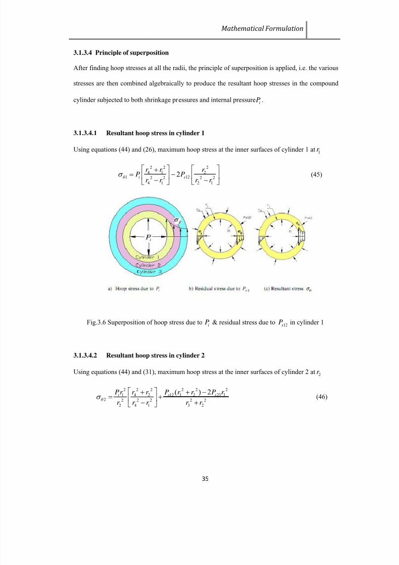
3.1.3.4 Principle of superposition
After finding hoop stresses at all the radii, the principle of superposition is applied, i.e. the various
stresses are then combined algebraically to produce the resultant hoop stresses in the compound
cylinder subjected to both shrinkage pressures and internal pressure iP .
3.1.3.4.1
Resultant hoop stress in cylinder 1
Using equations (44) and (26), maximum hoop stress at the inner surfaces of cylinder 1 at1
r
2 2 2
4 1 21 122 2 2 2
4 1 2 1
2i s
r r r P P
r r r r
(45)
Fig.3.6 Superposition of hoop stress due toi
P & residual stress due to12s
P in cylinder 1
3.1.3.4.2 Resultant hoop stress in cylinder 2
Using equations (44) and (31), maximum hoop stress at the inner surfaces of cylinder 2 at2r
2 2 2 22 2
1 12 3 2 23 34 22 2 2 2 2 2
2 4 1 3 2
( ) 2i s s
Pr P r r P r r r
r r r r r
(46)
7/23/2019 STRESS AND BURST PRESSURE DETERMINATION OF SHRINK FITTED COMPOUND CYLINDRICAL PRESSURE VESSEL
http://slidepdf.com/reader/full/stress-and-burst-pressure-determination-of-shrink-fitted-compound-cylindrical 50/78
Mathematical Formulation
36
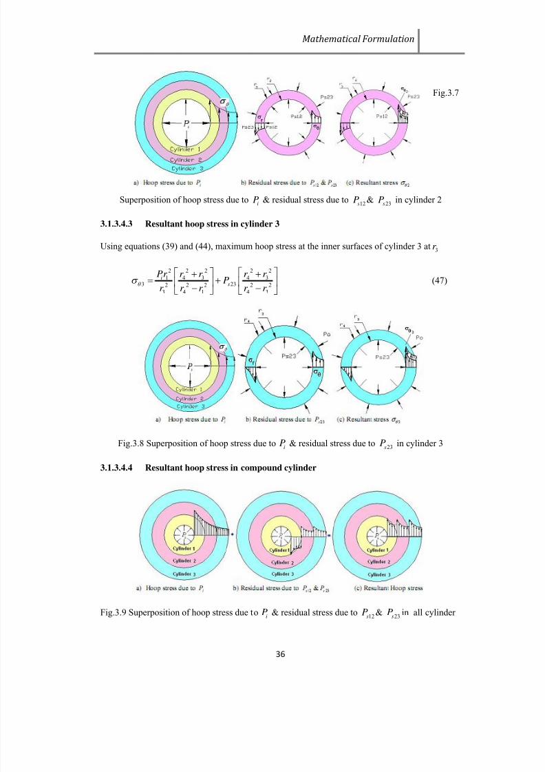
Fig.3.7
Superposition of hoop stress due toiP & residual stress due to
12sP &23sP in cylinder 2
3.1.3.4.3
Resultant hoop stress in cylinder 3
Using equations (39) and (44), maximum hoop stress at the inner surfaces of cylinder 3 at3r
2 2 2 2 21 4 3 4 3
3 232 2 2 2 2
3 4 1 4 3
is
Pr r r r r P
r r r r r
(47)
Fig.3.8 Superposition of hoop stress due toi
P & residual stress due to23s
P in cylinder 3
3.1.3.4.4
Resultant hoop stress in compound cylinder
Fig.3.9 Superposition of hoop stress due toi
P & residual stress due to12s
P &23s
P in all cylinder

7/23/2019 STRESS AND BURST PRESSURE DETERMINATION OF SHRINK FITTED COMPOUND CYLINDRICAL PRESSURE VESSEL
http://slidepdf.com/reader/full/stress-and-burst-pressure-determination-of-shrink-fitted-compound-cylindrical 51/78
Mathematical Formulation
37
3.1.3.5 Methodology of optimum compounder cylinder
To obtain optimum values of the contact (shrinkage) pressures12s
P and23s
P which will produce
equal hoop (tensile) stresses in all the three cylinders, maximum hoop stresses given by the
equations (45), (46) and (47) have been equated.
Equating equations (45) and (46) i. e.1 2
and rearranging,
2 2 2
4 1 2122 2 2 2
4 1 2 1
2i s
r r r P P
r r r r
=
2 2 2 22 2
1 12 3 2 23 34 2
2 2 2 2 2
2 4 1 3 2
( ) 2i s s
Pr P r r P r r r
r r r r r
2 2 22 2 2 2 2 2
3 2 32 4 1 1 4 112 232 2 2 2 2 2 2 2 2 2 2
2 1 3 2 4 1 2 4 1 3 2
22s i s
r r r r r r r r r P P P
r r r r r r r r r r r
(48)
Let the ratios1t = 2
1
r
r ,
2t = 3
2
r
r ,
3t = 4
3
r
r (49)
Let
2 2 2 2
2 4 1 21 2 2 2 2 2
2 1 4 1 2
21
21
12
1
2
1
r r r t k
r r r r t
t
t
(50
2 2 2 2 22 2 2 2 2
1 2 3 2 34 1 1 4 22 2 2 2 2 2 2 2 2 2 2 2
4 1 2 4 1 1 2 3 1 2 3
1 1
1 1
t t t t t r r r r r k
r r r r r t t t t t t
(51)
2 2
3 23 2 2 2
3 2 2
22
1
r t k
r r t
(52)
Hence equation (48) becomes
3212 23
1 1
s i s
k k P P P
k k
(53)
Equating equations (46) and (47) i. e. 2 3 and rearranging,
2 2 2 2 2 2 2 2 22 2
1 12 3 2 23 3 1 4 3 4 34 2232 2 2 2 2 2 2 2 2 2
2 4 1 3 2 3 4 1 4 3
( ) 2i s s i
s
Pr P r r P r Pr r r r r r r P
r r r r r r r r r r

7/23/2019 STRESS AND BURST PRESSURE DETERMINATION OF SHRINK FITTED COMPOUND CYLINDRICAL PRESSURE VESSEL
http://slidepdf.com/reader/full/stress-and-burst-pressure-determination-of-shrink-fitted-compound-cylindrical 52/78
Mathematical Formulation
38
2 2 2 2 2 2 22 2 2 2
3 2 4 3 4 3 31 1 4 212 232 2 2 2 2 2 2 2 2 2 2 2
3 2 3 4 1 2 4 1 4 3 3 2
2s i s
r r r r r r r r r r r P P P
r r r r r r r r r r r r
(54)
Let
2 2 2
4 2 2
4 2 2 24 1 2
1
1
r r t
k r r t
(55)
2 2 22 2 2 2 2 2
3 2 31 4 2 1 4 25 2 2 2 2 2 2 2 2 2 2 2 2
3 4 1 2 4 1 1 2 3 1 2 3
1 1
1 1
t t t r r r r r r k
r r r r r r t t t t t t
(56)
2 2 2 2
3 4 3 36 2 2 2 2 2
3 2 4 3 3
22
22
12
1
2
1
r r r t k
r r r r t
t
t
(57)
Hence equation (54) becomes
5 612 23
4 4
s i s
k k P P P
k k
(58)
Equations (32) and (36) have been solved to get12s
P and23s
P in terms ofi
P as follows,
5 6 2 3
12
4 6 1 3
/ /
/ /s i
k k k k P P
k k k k
(59)
5 4 2 1
23
3 1 6 4
/ /
/ /s i
k k k k P P
k k k k
(60)
Putting the values of1
t ,2
t and3
t , the equations (35) and (43) can be written as
2 2 2 22 2 1 2
12 12 232 2 2
2 1 1
1 1 12
1 1 1s s
r t t t P P
E t t t
(61)
2 2 23 3 122
23 23 2 2 2
3 2 2
1 1 21
1 1 1
ss
r t Pt P
E t t t
(62)

7/23/2019 STRESS AND BURST PRESSURE DETERMINATION OF SHRINK FITTED COMPOUND CYLINDRICAL PRESSURE VESSEL
http://slidepdf.com/reader/full/stress-and-burst-pressure-determination-of-shrink-fitted-compound-cylindrical 53/78
Mathematical Formulation
39
3.2 BURST PRESSURE DETERMINATION
3.2.1 BURST PRESSURE OF SINGLE LAYER CYLINDER
A widely used yield criterion is that of Von Mises. This criterion can be expressed by the
following relationship:
. . 3 y p s y
(63)
Where. . y p = yield-point stress of the material in the simple tension, pound per square inch
.s y =yield limit in simple shear, pound per square inch
We know that the maximum shear stress in three component system is:
max2
t r
s
(64)
Combining the above relationships with eq (63) gives:
.
2 3
y pt r (65)
By making allowance for sign convention with the compressive stressr
, negative, it may be
written as:
r t r
d r
dr
(66)
Substituting fort
in eq (66) by eq (65) gives:
.2
3
y p
r
dr d
r
(67)
Integration of eq (E) gives:

7/23/2019 STRESS AND BURST PRESSURE DETERMINATION OF SHRINK FITTED COMPOUND CYLINDRICAL PRESSURE VESSEL
http://slidepdf.com/reader/full/stress-and-burst-pressure-determination-of-shrink-fitted-compound-cylindrical 54/78
Mathematical Formulation
40
. .2ln
3
y p o
i
r p
r
(68)
Where p = internal pressure required to stress the outer surface to the yield point, pound per
square inch
. . y p = yield point of the shell material in single tention, pound per square inch
or =outside radius of the vessel
ir = inside radius of the vessel
Equation (68) was derived for a ideal plastic solid. For this ideal condition the yield strength and
tensile strength have the same value; therefore the bursting strength would be that predicted by
either eq (68) or eq (69).
. .2
ln3
t s o
i
r p
r
(69)
Where. .t s = ultimate tensile strength, pound per square inch
In the actual case for ordinary metals the ultimate tensile stress is appreciably higher the
yield strength, and the stress at bursting will be lie between the yield and ultimate strengths.
Faupel has proposed that eqs. (68) and (69) be modified as follows:
. . . .. . . .
. . . .
2 2ln 1 ln
3 3
y p y pt s o t s o
t s i t s i
r r p
r r
(70)
Equation (70) reduces to:
. . . .
. .
2ln 2
3
y p y po
i t s
r p
r
(71)

7/23/2019 STRESS AND BURST PRESSURE DETERMINATION OF SHRINK FITTED COMPOUND CYLINDRICAL PRESSURE VESSEL
http://slidepdf.com/reader/full/stress-and-burst-pressure-determination-of-shrink-fitted-compound-cylindrical 55/78
Mathematical Formulation
41
Equations (70) and (71) proportionally weight the stress values to their ratios; thus, when
the ratio…… is equal to 0.25, Eq (68) contributes 75% and Eq (69) contributes 25% to the
bursting pressure. Faupel reported the tests on the rapture of nearly 100 thick-walled cylinders
fabricated from a variety of high strength steels and Equation (71) was reliable within +-15% for
predicting the observed rapture pressure on a 90% certainty.
3.2.2
BURST PRESSURE OF TWO LAYER COMPOUND CYLINDER
Stress generated in interference between inner tube and jacket due to only for the internal
pressurei
P (excluding the shrinkage pressure) is
2
2 21 3
22 223 1
1i
t atD
PD D
D D D
To generate 2t atD
stress, pressure required at the interference (int er
p )
2
2 2
int 2 3
22 223 2
1er
t atD
P D D
D D D
Or, 2
2 2
3 2int 2 2
3 2
er t atD
D DP
D D
Total interference pressure in the inner surface of the jacket
int inter er total p p P
But pressure required at the inner surface of jacket to burst the jacket of the compound cylinder
from equation (1)
. . . .
. .
2ln 2
3
y p y pob
i t s
r p
r
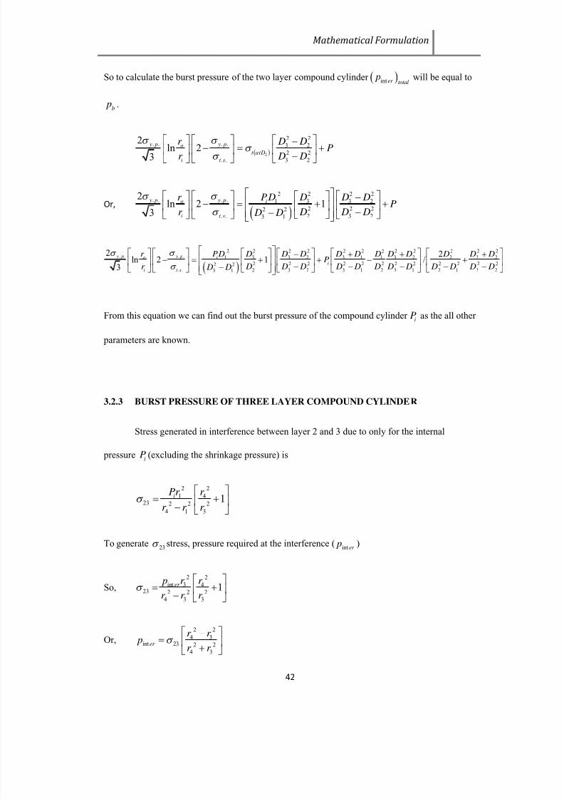
7/23/2019 STRESS AND BURST PRESSURE DETERMINATION OF SHRINK FITTED COMPOUND CYLINDRICAL PRESSURE VESSEL
http://slidepdf.com/reader/full/stress-and-burst-pressure-determination-of-shrink-fitted-compound-cylindrical 56/78
Mathematical Formulation
42
So to calculate the burst pressure of the two layer compound cylinder int er total p will be equal to
b p .
2
2 2. . . . 3 2
2 2
. . 3 2
2 ln 23
y p y po
t atD
i t s
r D D Pr D D
Or,
2 2 2 2. . . . 1 3 3 2
2 2 22 2. . 2 3 23 1
2ln 2 1
3
y p y po i
i t s
r P D D D DP
r D D D D D
2 2 2 2 2 2 2 2 2 22 2. . . . 1 3 3 2 3 1 3 2 3 21 2
2 2 2 2 2 2 2 2 2 2 2 22 2. . 2 3 2 3 1 2 3 1 2 1 3 23 1
2 2ln 2 1 /
3
y p y po ii
i t s
r PD D D D D D D D D D D DP
r D D D D D D D D D D D D D D
From this equation we can find out the burst pressure of the compound cylinderiP as the all other
parameters are known.
3.2.3 BURST PRESSURE OF THREE LAYER COMPOUND CYLINDER
Stress generated in interference between layer 2 and 3 due to only for the internal
pressurei
P (excluding the shrinkage pressure) is
2 2
1 423 2 2 2
4 1 3
1iPr r
r r r
To generate23 stress, pressure required at the interference (
int er p )
So,
2 2
int 3 423 2 2 2
4 3 3
1er p r r
r r r
Or,
2 2
4 3int 23 2 2
4 3
er
r r p
r r
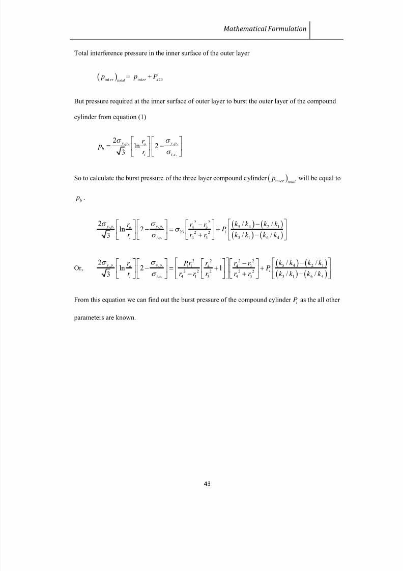
7/23/2019 STRESS AND BURST PRESSURE DETERMINATION OF SHRINK FITTED COMPOUND CYLINDRICAL PRESSURE VESSEL
http://slidepdf.com/reader/full/stress-and-burst-pressure-determination-of-shrink-fitted-compound-cylindrical 57/78
Mathematical Formulation
43
Total interference pressure in the inner surface of the outer layer
int er total p =
inter p +
23sP
But pressure required at the inner surface of outer layer to burst the outer layer of the compound
cylinder from equation (1)
. . . .
. .
2ln 2
3
y p y pob
i t s
r p
r
So to calculate the burst pressure of the three layer compound cylinder int er total p will be equal to
b p .
2 2. . . . 5 4 2 14 3
23 2 2
. . 4 3 3 1 6 4
2 / /ln 2
/ /3
y p y poi
i t s
k k k k r r r P
r r r k k k k
Or,
2 2 22. . . . 5 4 2 11 4 34
2 2 2 2 2
. . 4 1 3 4 3 3 1 6 4
2 / /ln 2 1
/ /3
y p y po ii
i t s
k k k k r Pr r r r P
r r r r r r k k k k
From this equation we can find out the burst pressure of the compound cylinder iP as the all other
parameters are known.

7/23/2019 STRESS AND BURST PRESSURE DETERMINATION OF SHRINK FITTED COMPOUND CYLINDRICAL PRESSURE VESSEL
http://slidepdf.com/reader/full/stress-and-burst-pressure-determination-of-shrink-fitted-compound-cylindrical 58/78
Chapter- 4
Analytical Model
This chapter named as Analytical Model where a certain problem is considered and
stress analysis and burst pressure determination is done for corresponding single layer thick
cylinder, two layer compound cylinder and three layer compound cylinder.

7/23/2019 STRESS AND BURST PRESSURE DETERMINATION OF SHRINK FITTED COMPOUND CYLINDRICAL PRESSURE VESSEL
http://slidepdf.com/reader/full/stress-and-burst-pressure-determination-of-shrink-fitted-compound-cylindrical 59/78
Analytical Model
45
4.1 STRESS ANALYSIS
4.1.1 STRESS ANALYSIS OF SINGLE LAYER CYLINDER
Let us consider a thick cylinder with= 25 mm and = 50 mm subjected to an internal
pressure 35 Mpa.
So hoop stress in the inner surface from Lame’s Equation
i = 58.333 Mpa
Hoop stress in the outer surface from Lame’s Equation
0 = 23.333 Mpa
4.1.2
STRESS ANALYSIS OF TWO LAYER COMPOUND CYLINDER
Let us consider a two layer compound cylinder with1r =25mm or
1 D = 50mm,
2r
=37.50mm or2
D =75mm and3
r =50mm or3
D =100mm subjected to an internal pressure 35
Mpa. The material for all three layer is structural steel with E = 210 Gpa, = 0.3,. . y p f =250
Mpa,. .t s
f =460 Mpa.
4.1.2.1
STRESSES DUE TO INTERNAL PRESSURE (i
P ):
Substituting the proper values in equations (14), (15), (16), we got the tangential stresses
at radius1r ,
2r and
3r are:
Table 4.1. Stresses due to internal pressure:
r 25 37.5 50
t 58.35 32.42 23.34
4.1.2.2
STRESSES DUE TO SHRINKAGE PRESSURE ( P ):
Substituting the proper values in equations (17), (18), (19) and (20), we got the tangential
stresses for the shrinkage pressure ( P ) for jacket and inner tube at radius1r , 2r and
3r are:

7/23/2019 STRESS AND BURST PRESSURE DETERMINATION OF SHRINK FITTED COMPOUND CYLINDRICAL PRESSURE VESSEL
http://slidepdf.com/reader/full/stress-and-burst-pressure-determination-of-shrink-fitted-compound-cylindrical 60/78
Analytical Model
46
Table 4.2. Stresses due to shrinkage pressure:
For jacket
r 37.5 50
t 3.57 P 2.57 P
For inner tube
r 25 37.5
t -3.6 P -2.6 P
4.1.2.3
TOTAL SHRINKAGE INTERFERENCE ( ):
Substituting the proper value in Eq (13), we got the shrinkage interference ( ) = 0.008
mm.
The inner diameter of the jacket should be (75 – 0.008) or 74.992 mm.
Table 4.3. Resultant stresses:
Inner tube Jacket
r = 25 r =37.5 r = 37.5 r = 50
Stresses due to P b
(P b=332.78Mpa)
555.74 309.49 309.49 222.96
Stresses due to P
(P= 34.34 Mpa)
-123.4 -89.28 122.59 88.25
Resultant stresses 432.34 220.21 432.08 311.21
4.1.3
STRESS ANALYSIS OF THREE LAYER COMPOUND CYLINDER
Let us consider a three layer compound cylinder with1r =25mm,
2r =33.33mm,
3r
=41.67mm and4r =50mm subjected to an internal pressure 35 Mpa . The material for all three
layer is structural steel with E = 210 Gpa, = 0.3,. . y p f =250 Mpa,
. .t s f =460 Mpa.

7/23/2019 STRESS AND BURST PRESSURE DETERMINATION OF SHRINK FITTED COMPOUND CYLINDRICAL PRESSURE VESSEL
http://slidepdf.com/reader/full/stress-and-burst-pressure-determination-of-shrink-fitted-compound-cylindrical 61/78
Analytical Model
47
Substituting these value in the equation (5) and (6) we will get,
12sP = 0.1048iP
23sP = 0.0673 iP
Substituting the value of12sP and
23sP in the equation (2), (3) and (4) we will get,
1 =
2 =
3 = 1.188
iP
Also substituting in the equation (7) and (8) we will get,
12 = 0.000083957
iP
23 =0.00005547iP
Table 4.4. Parameter due to internal pressure 35 Mpa
1
2
3
12sP 23sP
12
23
41.58 41.58 41.58 3.668 2.3555 0.00294 0.00194
4.2
BURST PRESSURE DETERMINATION
4.2.1
BURST PRESSURE OF SINGLE LAYER
From Faupel Equation (71) burst pressure for the thick cylinder is
b p = 291.44 Mpa
Stress generated due to burst pressure in the inner side
i = 485 Mpa
Stress generated due to burst pressure in the out side
0 = 194 Mpa
4.2.2
BURST PRESSURE OF TWO LAYER COMPOUND CYLINDER
Let assume pressure required in the inner surface to burst the compound cylinder = P b
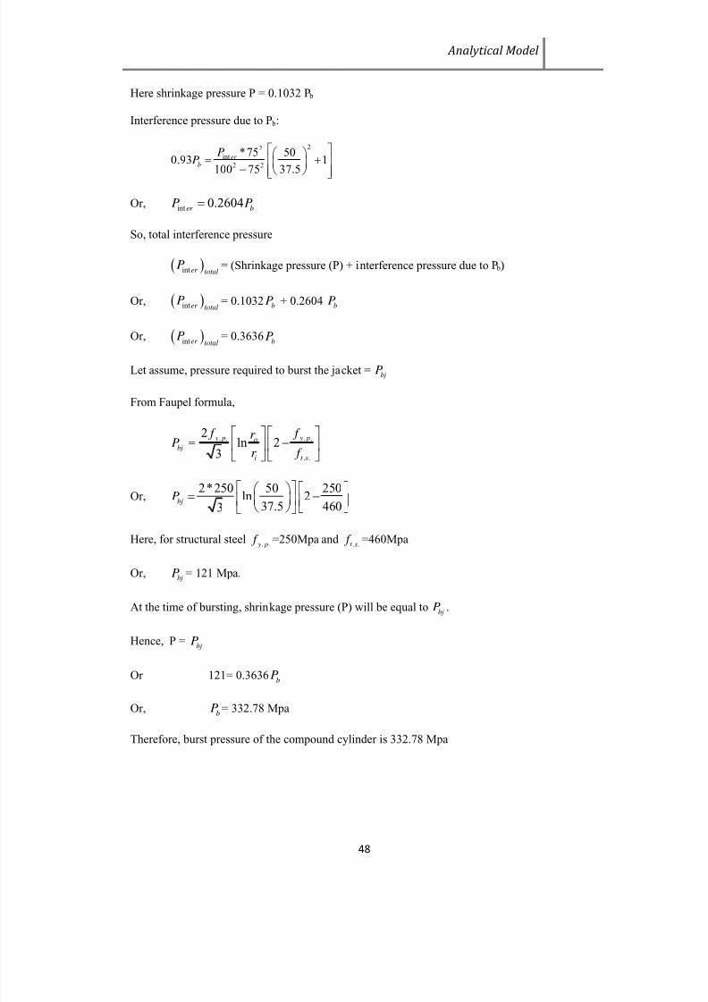
7/23/2019 STRESS AND BURST PRESSURE DETERMINATION OF SHRINK FITTED COMPOUND CYLINDRICAL PRESSURE VESSEL
http://slidepdf.com/reader/full/stress-and-burst-pressure-determination-of-shrink-fitted-compound-cylindrical 62/78
Analytical Model
48
Here shrinkage pressure P = 0.1032 P b
Interference pressure due to P b:
22
int
2 2
*75 500.93 1
100 75 37.5
er b
PP
Or,int 0.2604
er bP P
So, total interference pressure
inter totalP = (Shrinkage pressure (P) + interference pressure due to P b)
Or, inter totalP = 0.1032 bP + 0.2604 bP
Or, inter totalP = 0.3636
bP
Let assume, pressure required to burst the jacket =bj
P
From Faupel formula,
bjP =
. . . .
. .
2ln 2
3
y p y po
i t s
f f r
r f
Or,2*250 50 250
ln 237.5 4603
bjP
Here, for structural steel. . y p
f =250Mpa and. .t s f =460Mpa
Or,bjP = 121 Mpa.
At the time of bursting, shrinkage pressure (P) will be equal tobj
P .
Hence, P =bj
P
Or 121= 0.3636b
P
Or,b
P = 332.78 Mpa
Therefore, burst pressure of the compound cylinder is 332.78 Mpa
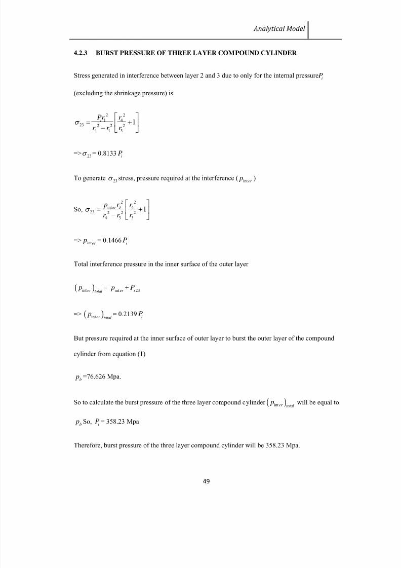
7/23/2019 STRESS AND BURST PRESSURE DETERMINATION OF SHRINK FITTED COMPOUND CYLINDRICAL PRESSURE VESSEL
http://slidepdf.com/reader/full/stress-and-burst-pressure-determination-of-shrink-fitted-compound-cylindrical 63/78
Analytical Model
49
4.2.3 BURST PRESSURE OF THREE LAYER COMPOUND CYLINDER
Stress generated in interference between layer 2 and 3 due to only for the internal pressureiP
(excluding the shrinkage pressure) is
2 2
1 423 2 2 2
4 1 3
1iPr r
r r r
=>23 = 0.8133
iP
To generate23
stress, pressure required at the interference (int er p )
So,
2 2
int 3 423 2 2 2
4 3 3
1er p r r
r r r
=>inter
p = 0.1466i
P
Total interference pressure in the inner surface of the outer layer
inter total p =
inter p +
23sP
=> inter total p = 0.2139
iP
But pressure required at the inner surface of outer layer to burst the outer layer of the compound
cylinder from equation (1)
b p =76.626 Mpa.
So to calculate the burst pressure of the three layer compound cylinder inter total p will be equal to
b p So,
iP = 358.23 Mpa
Therefore, burst pressure of the three layer compound cylinder will be 358.23 Mpa.

7/23/2019 STRESS AND BURST PRESSURE DETERMINATION OF SHRINK FITTED COMPOUND CYLINDRICAL PRESSURE VESSEL
http://slidepdf.com/reader/full/stress-and-burst-pressure-determination-of-shrink-fitted-compound-cylindrical 64/78
Chapter-5
FEM Analysis
This chapter named as FEM Analysis where a finite element analysis is done using ANSYS
Workbench v11 software and the stresses and burst pressure of single layer thick cylinder, two
layer compound cylinder and three layer compound cylinder is validated.

7/23/2019 STRESS AND BURST PRESSURE DETERMINATION OF SHRINK FITTED COMPOUND CYLINDRICAL PRESSURE VESSEL
http://slidepdf.com/reader/full/stress-and-burst-pressure-determination-of-shrink-fitted-compound-cylindrical 65/78
FEM Analysis
51
5.1 STRESS ANALYSIS
5.1.1. STRESS ANALYSIS OF A SINGLE LAYER CYLINDER
Table 5.1. Data for modeling in ANSYS
iP 1
D 2 D
35 50 100
Fig.5.1 Maximum principal stress in thick cylinder
5.1.2. STRESS ANALYSIS OF TWO LAYER COMPOUND CYLINDER
Table 5.2. Data for modeling in ANSYS
iP 1
D 2 D 2i
D 3 D
35 50 75 74.992 100 0.008
Where,
D1 ,D2 = inner and outer diameter of the tube
D2i, D3 = inner and outer diameter of the jacket
Shrink fit is applied between tube and jacket in ANSYS Workbench. Contact between tube and
jacket is applied using contact tool in ANSYS Workbench.
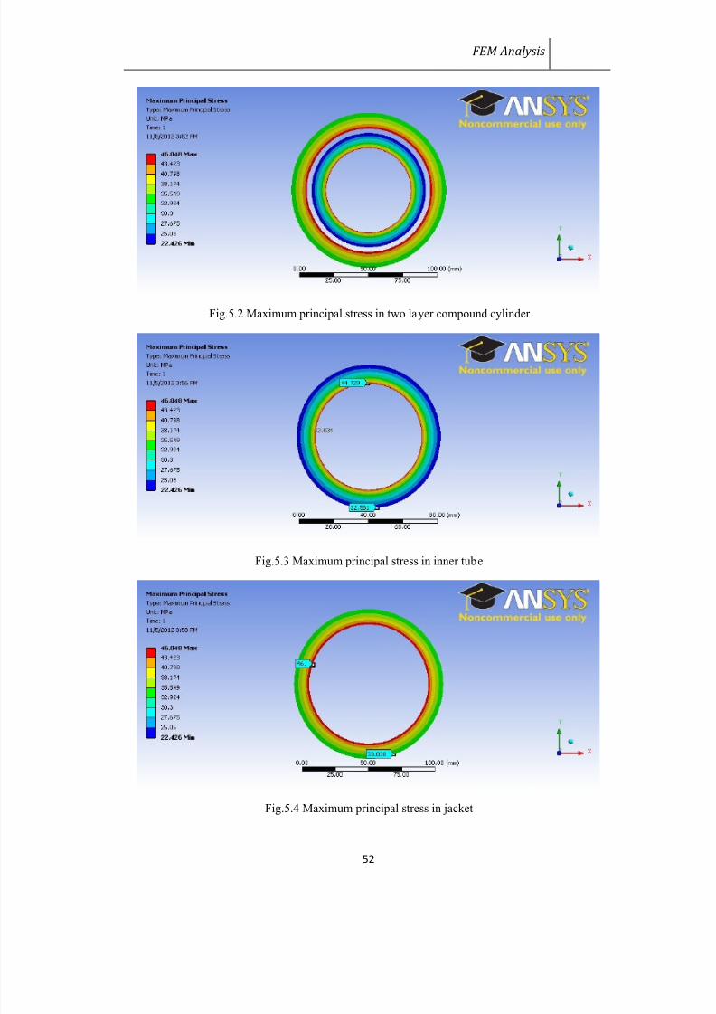
7/23/2019 STRESS AND BURST PRESSURE DETERMINATION OF SHRINK FITTED COMPOUND CYLINDRICAL PRESSURE VESSEL
http://slidepdf.com/reader/full/stress-and-burst-pressure-determination-of-shrink-fitted-compound-cylindrical 66/78
FEM Analysis
52
Fig.5.2 Maximum principal stress in two layer compound cylinder
Fig.5.3 Maximum principal stress in inner tube
Fig.5.4 Maximum principal stress in jacket

7/23/2019 STRESS AND BURST PRESSURE DETERMINATION OF SHRINK FITTED COMPOUND CYLINDRICAL PRESSURE VESSEL
http://slidepdf.com/reader/full/stress-and-burst-pressure-determination-of-shrink-fitted-compound-cylindrical 67/78
FEM Analysis
53
5.1.3. STRESS ANALYSIS OF THREE LAYER COMPOUND CYLINDER
Table 5.3 Data for modeling in ANSYS
iP 1 D 2 D 2i D 3 D 3i D 4 D 12 23
35 50 66.66 66.60 83.34 83.30 100 0.00294 0.00194
Fig.5.5 Maximum principal stress in three layer compound cylinder
5.2. BURST PRESSURE DETERMINATION
5.2.1. BURST PRESSURE OF SINGLE LAYER
Table5.4: Data for modeling Elastic break-down pressure and burst pressure
1 D
2 D
50 100

7/23/2019 STRESS AND BURST PRESSURE DETERMINATION OF SHRINK FITTED COMPOUND CYLINDRICAL PRESSURE VESSEL
http://slidepdf.com/reader/full/stress-and-burst-pressure-determination-of-shrink-fitted-compound-cylindrical 68/78
FEM Analysis
54
Fig.5.6 Maximum principal stress due to Elastic break-down pressure
Fig.5.7 Maximum principal stress due to burst pressure
5.2.2. BURST PRESSURE OF TWO LAYER COMPOUND CYLINDER
Table 5.5 Data for modeling in ANSYS
1 D 2
D 2i D 3
D
50 75 74.924 100 0.076

7/23/2019 STRESS AND BURST PRESSURE DETERMINATION OF SHRINK FITTED COMPOUND CYLINDRICAL PRESSURE VESSEL
http://slidepdf.com/reader/full/stress-and-burst-pressure-determination-of-shrink-fitted-compound-cylindrical 69/78
FEM Analysis
55
Fig.5.8 Maximum principal stress due to burst pressure
Using Design of Experiment in ANSYS Workbench, the pressure required to generate maximum
principle stress 332.34Mpa is 327Mpa.
5.2.3. BURST PRESSURE OF THREE LAYER COMPOUND CYLINDER
Table 5.6 Data for modeling Elastic-breakdown pressure in ANSYS
1 D
2 D
2i D
3 D
3i D
4 D
12
23
50 66.66 66.625 83.34 83.317 100 0.0177 0.0116
Where
1 D ,
2 D = inner & outer diameters of cylinder 1 respectively.
2i D ,
3 D = inner & outer diameters of cylinder 2 respectively for shrink fit.
3i D ,
4 D = inner & outer diameters of cylinder 3 respectively for shrink fit.

7/23/2019 STRESS AND BURST PRESSURE DETERMINATION OF SHRINK FITTED COMPOUND CYLINDRICAL PRESSURE VESSEL
http://slidepdf.com/reader/full/stress-and-burst-pressure-determination-of-shrink-fitted-compound-cylindrical 70/78
FEM Analysis
56
Fig. 5.9 Maximum principle stress due to Elastic break-down Pressure
Using Design of Experiment in ANSYS Workbench, the pressure required to generate maximum
principle stress 250 Mpa is 203 Mpa.
Table 5.7. Data for modeling Burst pressure in ANSYS
1 D
2 D
2i D
3 D
3i D
4 D
12 23
50 66.66 66.60 83.34 83.30 100 0.0301 0.0199
Fig. 5.10 Maximum principle stress due to Burst Pressure
Using Design of Experiment in ANSYS Workbench, the pressure required to generate maximum
principle stress 425. 57 Mpa (1.188 * 358.23) on the inner surface of the outer layer is 354 Mpa.

7/23/2019 STRESS AND BURST PRESSURE DETERMINATION OF SHRINK FITTED COMPOUND CYLINDRICAL PRESSURE VESSEL
http://slidepdf.com/reader/full/stress-and-burst-pressure-determination-of-shrink-fitted-compound-cylindrical 71/78
Chapter-6
Discussion
The sixth chapter is the most important chapter named as Discussion. Here the results of
analytical model and FEM analysis are compared and error is also computed and shown that the
errors are in acceptable limits.

7/23/2019 STRESS AND BURST PRESSURE DETERMINATION OF SHRINK FITTED COMPOUND CYLINDRICAL PRESSURE VESSEL
http://slidepdf.com/reader/full/stress-and-burst-pressure-determination-of-shrink-fitted-compound-cylindrical 72/78
Discussion
58
6.1. SINGLE LAYER COMPOUND CYLINDER
Table6.1 . Comparison of burst pressure
Burst pressure(P b)
Analytical 291.44
ANSYS Workbench 291
%Error Less than 1%
6.2. TWO LAYER COMPOUND CYLINDER
Table 6.2. Comparison of burst pressure
Burst pressure(P b)
Analytical 332.78
ANSYS Workbench 327
%Error 1.74
6.3. THREE LAYER COMPOUND CYLINDER
Table 6.3. Comparison of Burst Pressure
Burst Pressure
Analytical 358.23
ANSYS Workbench 354
%Error 1.18

7/23/2019 STRESS AND BURST PRESSURE DETERMINATION OF SHRINK FITTED COMPOUND CYLINDRICAL PRESSURE VESSEL
http://slidepdf.com/reader/full/stress-and-burst-pressure-determination-of-shrink-fitted-compound-cylindrical 73/78
Chapter-7
Conclusions
This chapter is the generalConclusion , where merits and demerits of the present work
are dealt and the readers of the thesis are directed towards the future scope of work or further
continuation or modification of the present work.

7/23/2019 STRESS AND BURST PRESSURE DETERMINATION OF SHRINK FITTED COMPOUND CYLINDRICAL PRESSURE VESSEL
http://slidepdf.com/reader/full/stress-and-burst-pressure-determination-of-shrink-fitted-compound-cylindrical 74/78
Conclusions
60
CLOSING REMARK
The combination of advanced materials and techniques of multi-layering processes are
being employed to develop pressure vessels that have improved pressure capacity, fatigue life,
and reduced weight that enables pressure vessels to ensure higher performance and more
reliability.
In this thesis of shrink fitted compound cylinder, the stress analysis is studied and at the
same time the burst pressure of the compound cylinder is determined. From the discussion it is
clear that the difference in analytical and ANSYS Software results are within acceptable
limits. This difference is due to numerical techniques of Finite Element Method in ANSYS. Since
analytical results are validated by FEM calculations, the design methodology proposed in this
paper can be successfully applied into the real-world mechanical applications for the stress
analysis and to determine the burst pressure of multi-layered compound cylinders to assure best
utilization of material.
From this work, following conclusions are drawn:
I.
Maximum hoop stress at the innermost surface decreases due to compounding. Thus
compound cylinder with same dimension of monobloc cylinder can withstand high
pressure without actual failure.
II.
Compounding of vessel decreases the difference between maximum and minimum hoop
stress. Thus material is safer compared to monobloc or autofrettaged vessel as there is
approximate uniform stress dustribution.
III. Though hoop stress decreases with increase in number of layers, but decrease in hoop
stress is more effective up to n=3. Hence, number of layers used in pressure vessel
depends on requirement.
IV. The burst pressure of compound cylinder is higher than the monobloc cylinder upto three
layer. For the given problem in the thesis the burst pressure of monobloc cylinder is 291
Mpa where of two layer and three layer compound cylinder with same dimension and
same material properties is 332.78 Mpa and 358.23 Mpa.

7/23/2019 STRESS AND BURST PRESSURE DETERMINATION OF SHRINK FITTED COMPOUND CYLINDRICAL PRESSURE VESSEL
http://slidepdf.com/reader/full/stress-and-burst-pressure-determination-of-shrink-fitted-compound-cylindrical 75/78
Conclusions
61
V.
As the outer layer of compound cylinder is subjected to burst first. So provision can be
made to increase the burst pressure using harder material for the outer layer.
7.2 FUTURE SCOPE OF WORK
In this thesis we solely dedicate our focus to the stress analysis and burst pressure
determination of multi layer shrink fitted compound cylindrical pressure vessel. we selected a
common same material for the each layer.
In this present work we did not focus our attention on the fatigue life of the vessel, though
it is well aware that compounding increases fatigue life. There should be a scope remains.
Other than compounding there are other techniques that help increase the pressure
capacity and reliability – like autofrettage technology. Autofrettaging and shrink fitting in
different combination can do the trick. In that case, the percentage of Autofrettage and degree of
interference fit serve the purpose.
The main motto of the study of pressure vessel is to increase pressure capacity and
reliability with adequate safety at a time. And also at the same time it should be more economical.
For these reasons, we need to optimise all the facts related to its performance. Hence optimization
has a crucial role and future prospect in the study of multi layered pressure vessel technology.
This can be done extensively using different material data, different material model,
selecting different types of strain hardening and different yield criteria in different combinations.
In the present time many research are going on functionally graded material. So we also
can incorporate FGM to analyze the same thing.

7/23/2019 STRESS AND BURST PRESSURE DETERMINATION OF SHRINK FITTED COMPOUND CYLINDRICAL PRESSURE VESSEL
http://slidepdf.com/reader/full/stress-and-burst-pressure-determination-of-shrink-fitted-compound-cylindrical 76/78
References
62
[1]. Lamé, G. “Leçons sur la Théorie Mathématique de l’Élasticité des Corps Solides,”
Gauthier-Villars, Paris, 1852.
[2]. “Modern Weapons and Weapon Systems,” Technology of War article, Encyclopædia
Britannica, Volume 29, 1992.
[3]. Rodman, T J. “Improvement in Casting Ordnance,” US Patent No. 5236, August 14,
1847.
[4]. Macrae, A E. “Overstrain in Metals,” HM Stationery Office, London, 1930.
[5]. Manning, W R D. “High Pressure Engineering, Bulleid Memorial Lectures,” University
of Nottingham, Volume II, 1963.
[6]. Dirmoser, O. “Design of High Strength Gun Tubes (Built up and Cold Worked) having
Normal and Artificially Raised Elastic Limit,” Vienna Technical College, Vienna,
Austria, 1931.
[7]. Faupel, J H. “Residual Stresses in Heavy-Wall Cylinders,” Journal of the Franklin
Institute, Volume 259, Issue 5, pp. 405-420, 1955.
[8]. Brownell, Llyod E.; Young, Edwin H. (2009): Equipment Design, Wiley Eastern Limited,
Chapter- (14 & 15)
[9]. Bhandari V. B. (2010): Design of Machine Elements, Tata McGraw Hill Education
Private Limited Chapter- (22)
[10]. ASME (2007): An International Code, “ 2007 ASME Boiler & Pressure Vessel Code,”
KD-412, pp- 74.
[11]. Kumar, et al. (2011): Optimization of Shell Thickness in Multilayer Pressure Vessels and
Study on Effect of Shell on Maximum Hoops Stress, International Journal of Engineering
Science and Technology (IJEST). Vol. 3, No. 4, April
[12]. Miraje Ayub A. and Patil Sunil A. (2011): Optimum Thickness of Three-Layer Shrink-Fit
Compound Cylinder for Uniform Stress Distribution, International Journal of Advances
in Engineering & Technology, Vol. 3, Issue 2, May.

7/23/2019 STRESS AND BURST PRESSURE DETERMINATION OF SHRINK FITTED COMPOUND CYLINDRICAL PRESSURE VESSEL
http://slidepdf.com/reader/full/stress-and-burst-pressure-determination-of-shrink-fitted-compound-cylindrical 77/78
References
63
[13]. Majzoobi G.H., Ghomi A. (2006): Optimisation of compound pressure cylinders, Journal
of Achievements in Materials and Manufacturing Engineering, Vol. 15. Issue 1-2,
March-April.
[14]. Patil Sunil A., (2005) “Optimum Design of compound cylinder used for storing
pressurized fluid”, ASME International Mechanical Engineering Congress and
Exposition (Proceeding of IMECE05), Nov 5-11,2005,Orlando, Florida USA.
[15]. Patil Sunil A., (2011) “Finite Element Analysis of optimized compound cylinder”,
Journal of Mechanical Engineering Research, Vol. 3(1), Issue March.
[16]. Miraje Ayub A., Patil Sunil A.,(2011) “Minimization of material volume of three
layer compound cylinder having same materials subjected to internal pressure”,
International Journal of Engineering, Science and Technology , Vol. 3, No. 8, 2011, pp.
26-40.
[17] Raparla Siva Krishna, Seshaiah T. (2012): Design and Analysis of Multilayer High
Pressure Vessels, International Journal of Engineering Research and Applications
(IJERA), Vol. 2, Issue 1, Jan-Feb 2012, pp. 355-361
[18] Kisioglu. (2009): Burst tests and Volume expansions of Vehicle Toroidal LPG fuel tanks,
TurkishJ.Eng.Env.Sci. 33 (2009) , 117 – 125.
[19] Kaptan, Kisioglu (2007): Determination of Burst Pressures and Failure Locations of
Vehicle LPG Cylinders, International Journal of Pressure Vessels and Piping, 84 (2007)
451–459
[20] Egemen Aksoley M., Ozcelik Babur, Bican Ismail. (2007): Comparison of Bursting
Pressure Results of LPG Tank using Experimental and Fnite Element Method, Journal of
Hazardous Materials 151 (2008) 699–709
[21] Mirzaei Majid. (2007): Failure Analysis of an Exploded Gas Cylinder, Engineering
Failure Analysis 15 (2008) 820–834

7/23/2019 STRESS AND BURST PRESSURE DETERMINATION OF SHRINK FITTED COMPOUND CYLINDRICAL PRESSURE VESSEL
http://slidepdf.com/reader/full/stress-and-burst-pressure-determination-of-shrink-fitted-compound-cylindrical 78/78
References
[22] Xue L., Widera G. E. O., Sang G. E. O. (2010): Parametric FEA Study of Burst Pressure
of Cylindrical Shell Intersections’, Journal of Pressure Vessel Technology, Vol. 132 /
031203-1
[23] Xu P., Zheng J.Y., Liu P.F. (2009): Finite Element Analysis of Burst Pressure of
Composit Hydrogen Storage Vessels, Materials and Design 30 (2009) 2295–2301
[24] Chuan-xiang ZHENG, Shao-hui LEI. (2006): Research on Bursting Pressure Formula of
Mild Steel Pressure Vessel’, Zheng et al. / J Zhejiang Univ SCIENCE A 2006 7(Suppl.
II):277-281
[25] Madenci Ergodan, Guven Ibrahim.: The Finite Element Method and Applications in
Engineering Using ANSYS.
[26]. Lawrence L. Kent: ANSYS Workbench Tutorial, ANSYS Release 10.