Embed Size (px)
Citation preview
EN-84-13
LnL
STRESS ANALYSISON
SCREW THREAD
A. R. YAO and J. A. DORAN0
AUGUST 1984
LUU
ENGIEERIG DRECTRAT
ROKILN REA
ROK SAN, LINIS629-5085 09 2 0 4

,,,
THIS DOCUMENT IS BEST QUALITY AVAILABLE. THE COPY
FURNISHED TO DTIC CONTAINED
A SIGNIFICANT NUMBER OF
PAGES WHICH DO NOT
REPRODUCE LEGIBLY.

BLANK PAGES IN THIS DOCUMENT WERE NOT FILMED
UNCLASSIFTIDSECURITY CLASSIFICATION OF THIS PAGE (hem Data Entered)
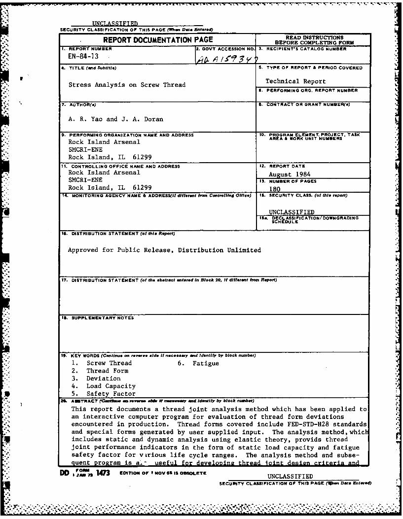
REPORT DOCUMENTATION PAGE BEFORE COMPLETING FORKI. REPORT NUMBER 2. GOVT ACCESSION NO. 3. RECIPIENT'S CATALOG NUMBER
EN -84 -13 , . I/_ _ _ _ _ _ _ _
4. TITLE (and Subtitle) S. TYPE OF REPORT & PERIOD COVERED
Stress Analysis on Screw Thread Technical Report6. PERFORMING ORG. REPORT NUMBER
7. AUTHOR(e) S. CONTRACT OR GRANT NUMBER(e)
A. R. Yao and J. A. Doran
9. PERFORMING ORGANIZATION NAME AND ADDRESS 10. PROGRAM ELEMENT. PROJECT. TASK
Rock Island Arsenal AREA & WORK UNIT NUMBERS
SMCRI-ENERock Island, IL 61299
II. CONTROLLING OFFICE NAME AND ADDRESS 12. REPORT DATE
Rock Island Arsenal August 1984SMCRI-ENE IS. NUMBER OF PAGES
Rock Island, IL 61299 18014. MONITORING AGENCY NAME & ADDRESS(Ih different from Controlling Office) IS. SECURITY CLASS. (of thli report)
UNCLASSIFIEDIS*. DECL ASSI FI CATION/ DOWNGRADING
SCHEDULE
IS. DISTRIBUTION STATEMENT (of this Report)
Approved for Public Release, Distribution Unlimited
17. DISTRIBUTION STATEMENT (of the abatract entered In Block 20, If different from Report)
1. SUPPLEMENTARY NOTES
L
19. KEY WORDS (Continue on revere side If necesary and tdentify by block number)
1. Screw Thread 6. Fatigue2. Thread Form3. Deviation4. Load Capacity5. Safety Factor
2[26 AEWSTAC (vtue sm ,e r e ml f nmeenwy aced Identify by block number)
This report documents a thread joint analysis method which has been applied toan interactive computer program for evaluation of thread form deviationsencountered in production. Thread forms covered include FED-STD-H28 standardsand special forms generated by user supplied input. The analysis method, whictincludes static and dynamic analysis using elastic theory, provids threadjoint performance indicators in the form of static load capacity and fatiguesafety factor for virious life cycle ranges. The analysis method and subse-quent program is a.- useful for develonine thread joint design criteria and
D FOre 17 EDITION OF I NOV 65 IS OBSOLETECJAN 7 3 UNCLASSIFIED
SECURITY CLASSIFICATION OF THIS PAGE (1ien Data Entered)
,. :*,
SECURITY CLASSFICATION OF THIS PAOE(Whoi D408 Xntot*0
Block 20. Abstract
verification of existing designs.
2
SECURITY CLASSIFICATION OF THIS PAGE(Whon Dt Enterod)
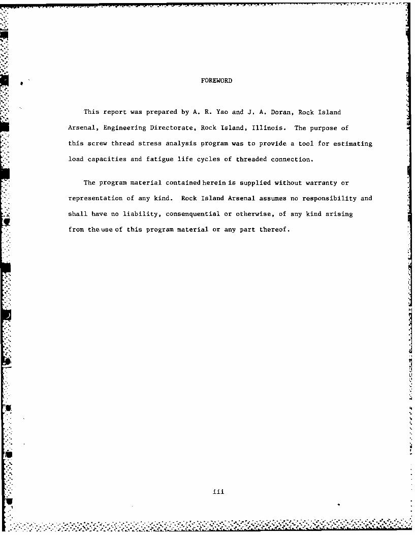
FOREWORD
This report was prepared by A. R. Yao and J. A. Doran, Rock Island
Arsenal, Engineering Directorate, Rock Island, Illinois. The purpose of
this screw thread stress analysis program was to provide a tool for estimating
load capacities and fatigue life cycles of threaded connection.
The program material contained herein is supplied without warranty or
representation of any kind. Rock Island Arsenal assumes no responsibility and
shall have no liability, consenquential or otherwise, of any kind arising
from the use of this program material or any part thereof.
iii
L!"
-~~~~ - 7.. 7. - j-~-
%
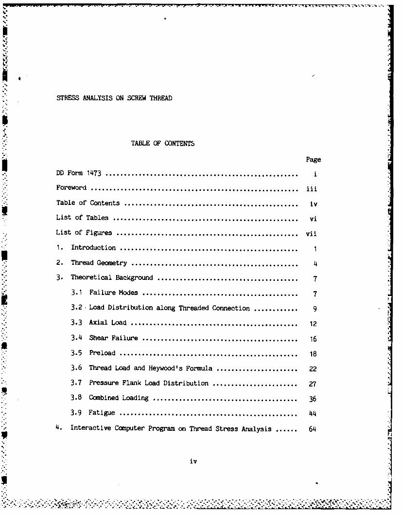
STRESS ANALYSIS ON SCREW THREAD
TABLE OF CONTENTS
Page
DD Form 1473 .................................................... i
Foreword ........................................................
Table of Contents ............................................... iv
List of Tables .................................................. vi
List of Figures ................................................. vii1. Introduction ................................................
1
2. Thread Geometry ................................... .......... 4
3. Theoretical Background ...................................... 7
3.1 Failure Modes .......................................... 7
3.2- Load Distribution along Threaded Connection ............ 9
3.3 Axial Load ............................................ 12
3.4 Shear Failure .................. . .... ................. 163.5 Preload ................................................
18
3.6 Thread Load and Heywood's Formula ...................... 22
3.7 Pressure Flank Load Distribution ....................... 27
3.8 Combined Loading ....................................... 36
3.9 Fatigue ................................................ 44
4. Interactive Computer Program on Thread Stress Analysis ...... 64
iv
a
5. Discussion ... . .. . . . . . . . .. . . . . . .. . . . . 69
6. References .................................................. 71
7. Appendices ................................................. Al
A.1 Program Variable List...................................A2
A.2 Common BLOCKS ......................................... A10
A.3 Compile and Load Instructions............... 0...........A12
A.'4 Main Program and Subroutines........................... A13
A.5 Example 1: V Thread.................................... A89
tA.6 Example 2: Acme Thread................................. A91
A-7 Example 3: Stub Acme Thread............................ A93
A.8 Example 4: Buttress Thread............................. A95
A.9 Example 5: PF20 Waterviet Special Thread...............A99
__ V
pig , - .""
LIST OF TABLES
TABLE Page
3.7.1 Calculated load distribution parameters ................ 35
3.9. 1 Reliability factor Cr .................................. 53
4.1 Thread Stress Analysis Information Input Form .......... 66
4.2 Example for Thread Stress Analysis Information Input Form 67
q
vi
........................
LIST OF FIGURES
FIGURE Page p
2. 1 Typical thread geometry ..................... . ......... 5
3.6.1 Typical thread form with Heywood's parameters ............ 25
3.7.1 Application of load to screw thread (Sopwith) ............ 28
3.7.2 Photoelastic stress patterns of thread projection ........ 30
3.7.3 Load distribution on pressure flank ...................... 32
3.7.4 Location of load diameter .................... 33
3.8.1 Locations of maximum fillet stresses due to axial load &
thread load .............................................. 37
3.8.2 Combined fillet stresses on fillet contour ............... 40
3.8.3 The state of stress at location of maximum fillet stress
due to combined loading .................................. 42
3.9.1 Generlized S-N diagram ................................... 45
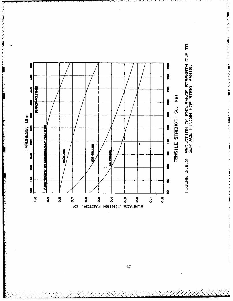
3.9.2 Reduction of endurance strength due to surface finish
for steel parts .......................................... 47
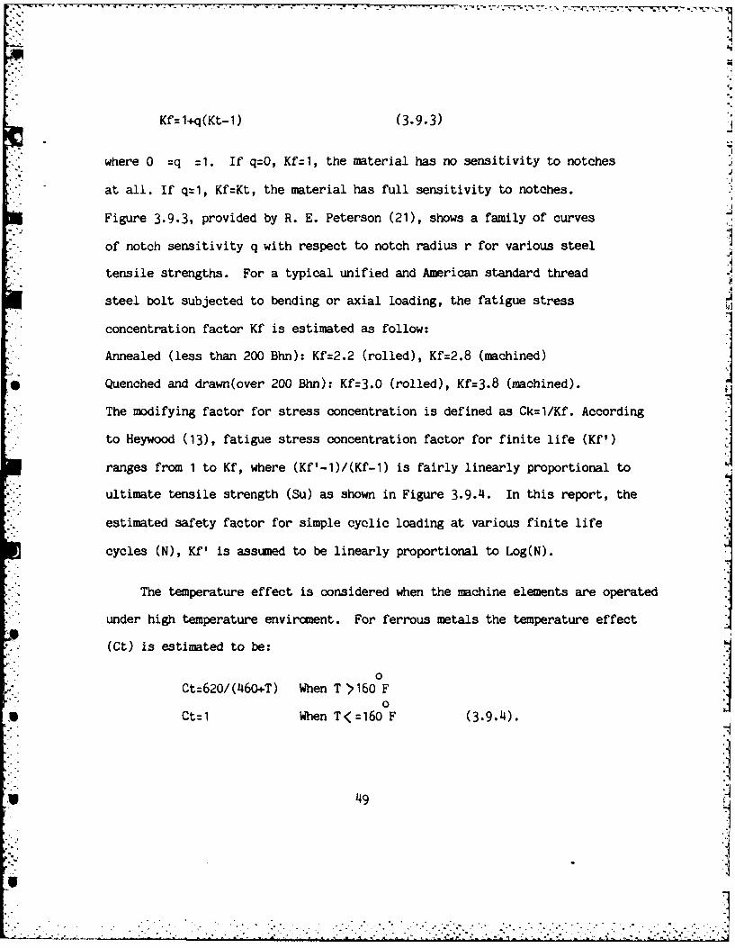
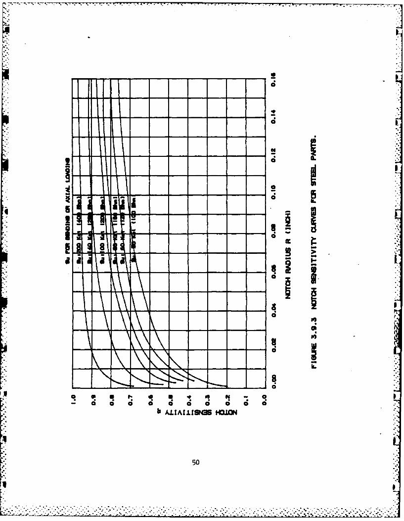
3.9.3 Notch sensitivity curves for steel parts ................ 50
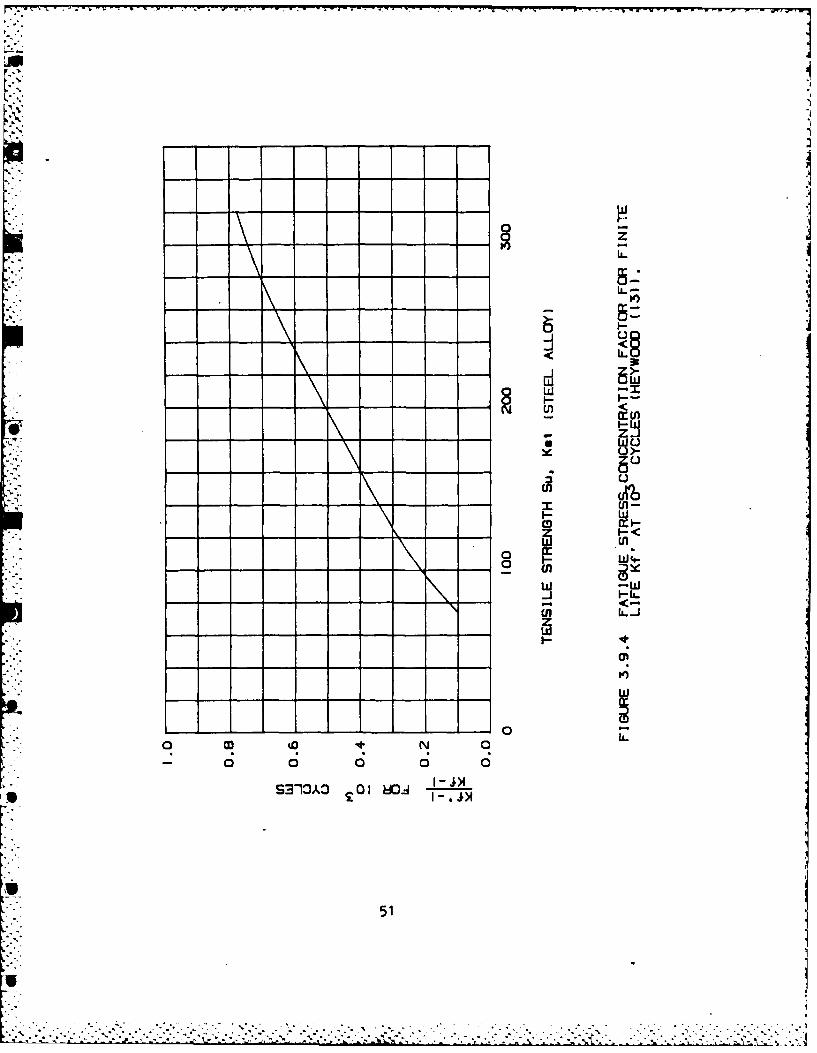
3.9.4 Fatigue stress concentration factor for finite life Kf'
3at 10 cycles ............................................ 51
3.9.5 Proposed fatigue fracture criteria on Sm-Sa diagram ...... 55
3.9.6 Sm-Sa diagram for ductile metals ......................... 57
vii
......... . ... ...
3.9.7 Fatigue strength diagram for alloy steel, Su=125 to
180 ksi axial loading .................................... 59
3.9.8 Three possible design overload for safety factor
calculation ........................................... 61
3.9.9 Safety factors corresponding to various fatigue life ..... 63
I
viii '
TJ
1. Introduction
During the past several years of production at Rock Island Arsenal,
approximately 10% of all submitted material nonconformances have directly
involved thread forms. Variations in minor, pitch, and major diameters
along with other geometry considerations in V, Acme, Buttress, and special
thread forms; may adversely affect the assembly, life, and strength of
a given thread joint. Nonconforming parts have ranged from common fast-
eners under static loading to recoil yokes and piston adapters subjected
to enormous weapon firing loads. The cost/scheduling impact and critical
function requirements have established a crucial need for a rapid and
reliable thread joint evaluation method.
Thread analysis procedures to date include (1) Precedent Method,
(2) Thread Class Substitution, (3) Routine Stress Analysis, and (4) Testing.
The Precedent Method, as the name implies, bases a thread nonconform-
ance evaluation on previous evaluations of similar types under similar
loading and environmental conditions, where these results may be derived
from calculations, experiments, or experience. This method is practical
and effective, being employed whenever a reasonable and verifiable
precedent case can be found. The quantitative "how much" or "how bad"
answers, however, must be obtained by other means.
The Class Substitution Method, somewhat similar in philosophy to
"' .'. ' i+ .' i '. - -i -_- -' - ..- -[ + . -++ .+i . ' . ' ' + i- -' -'. -.-. '- -" " . -i ' ..' i'-1
r:
the Precedent Method, uses the tolerance variations within thread class
specifications as a criterion for acceptance. The method is primarily a
"rule-of-thumb" approach and also lacks quantitative accessment of thread
joint performance. The Class Substitution Method, used only occasionally
for critical fit applications, does have the distinct advantage of pro-
viding distinct documented limits, but is generally so conservative as to
disqualify thread conditions that still possess adaquate strength.
Routine Stress Analysis, using the more readily available textbook
references, serve to provide quantitative analysis of limited accuracy,
being based on several simplifying and gross assumptions. Highly
detailed stress results, leading to more accurate analysis, is not
a simple exercise and must generally be conducted by persons having
that specialized discipline. Usually, evaluation response time for a
given occurance precludes this type of in-depth analysis.
The testing approach, used sparingly due to cost and time constraints,
offers perhaps the most accurate and verifiable means of analyzing thread
nonconformances. Testing as a sole means of evaluation, however, would
require experimental recreation of exact geometry and loading conditions
per given nonconformance. More general experiments designed to evaluate
"trends" due to certain geometry and load conditions can provide useful
and interesting results, but seldom provide the required degree of accuracy.
2

An alternative evaluative method, which is being documented in this
report, involves development of three-dimensional state-of-stress equations
using specific thread geometry relati )nships and Heywood's formula. Thorough
literature research on thread analysis, both domestic and foreign, have
confirmed and further refined this analytical approach to solve joint
strength of nonconforming threads. However, as with any analytical solution,
several key assumptions were required to simplify complicated geometries
and loading conditions. Some experimental data adopted from literatures
and mathematical model were integrated into an interactive computer program
for solution of user supplied thread geometry, applied loads and material
property parameters. In this report, both static analysis and fatigue
analysis were provided under assumption of elasticity.
3
2. Thread Geometry
A screw thread is a complex configuration comprised of several elements
and characteristics. According to definition of FED-STD-H28 (1) and ANSI BI
(2) handbooks, a screw thread is a ridge, usually of uniform section and
"." produced by forming a grove in the form of a cylinder. (Taper thread is not
included in this report.) A thread is a portion of a screw thread encompassed
by one pitch. On a single-start thread it is equal to one turn.
There are several basic thread forms such as V thread, Acme thread,
Buttress thread, square thread and special thread such as Watervliet 20/45
modified Buttress thread. Due to loading conditions and applications,
threads are identified with thread type, thread series, size, fit or class,
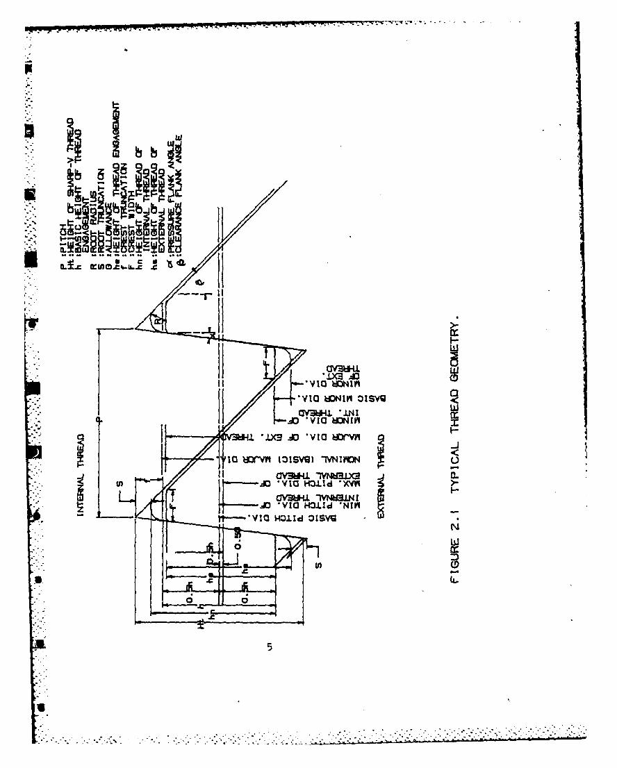
and some special specifications. Figure 2.1 shows a typical thread geometry.
For detail definition, geometry, allowance, tolerance and limit of size of
thread forms, FED-STD-H28 and ANSI B1 handbooks are recommended. Typical
thread forms, thread series and classes are listed as follow:
UNC: Unified coarse thread, Classes-1A,2A,3A,1B,2B and 3B.
UNF: Unified fine thread, Classes-1A,2A,3A,1B,2B and 3B.
UNEF: Unified extra fine thread, Classes-1A,2A,3A,1B,2B and 3B.
UNM: Unified miniature thread
UNJ: Unified controlled root radius thread, ANSI B1.15.
UNR: Unified controlled root radius thread, ANSI B1.14.
* . I4UN,6UN,8UN,12UN,16UN,20UN,28UN and 32UN: Unified thread,
V.
.4
- '.-&2
ww
OLL. L. a
M
IX7 I 0
w
OV3WI~. .L I.r
-0 ' VI .OI x
*0 - --- ~ *0*. * . .. - - - .. -LX X * . I - lU
Classes-1A,2A,3A,1B,2B and 3B.
ACME: Acme thread, two general applications for Acme thread used chiefly for
purpose of producing traversing motions on machines and tools. Acme
thread is divided into three general classes, 2G,3G and 4G, and five
centralizing classes, 2C,3C,4C,5C and 6C.
STUB A(ME: Used for unusual applications pertinent to Acme thread but where
a coarse pitch or shallow depth is required. While no class callout,
the Stub Acme corresponds to class 2G of the Acme thread.
BUTT and PUSH-BUTT: Buttress thread for pull or push type, used where high
stresses are along the thread axis in one direction only.
Classes-1A,2A,3A,1B,2B and 3B.
Thread design is to a large extent empirical and is partially based on
previous experience with similar designs and the judgment of the designer.
The interrelation of length of engagement, minimum major diameter of the
external thread, maximum minor diameter of the internal thread, and the
strength of the assembled thread needs to be understood and carefully
considered in order to produce the optimum design of a special thread. It
is not economical to use either a length of thread engagement which is longer
than required or shorter than that which will develop the full strength of
the externally threaded member. Other factors such as loading conditions
and geometry restrictions required careful analysis and adjustment of the
design with respect to selection of the diameter-pitch combination, the class
of thread, length of engagement, and minor and major diameter tolerances.
6
-:. ... . . . .. .. _. .. . . . . ....... . 1.... . . ..... . .. ........... -..... .. ..-. .. , .. .. . . .- -. ..
3. Theoretical Background
3.1 Failure Modes
The screw thread is one of the machine elements, in the form of a nut
and bolt or stud, which have widespread application for virtually every machine
and structure. A screw thread differs from a conventional cylindrical notched
specimen in that, firstly, a screw thread consists of a series of adjacent
notches and, secondly, the load is transmitted through the stress con-
centration, that is, the nut transmits the load to the bolt through the
flank and root radius of the thread. The threaded connections are, in
general, subjected to tension, compression, shear, bending and torsion,
statically and dynamically. Torsional stress is presented in the threaded
connection during tightening, however, the threaded connection will unwind
slightly during the initial period of operation under dynamic loading,
and relieve the torsional stress. In addition to the stress due to axial
loading (tension and compression), the thread contact surface transmits
bending stress at the thread roots.
Thread failure modes are mainly: (1) shear failure, and (2) failure
due to maximum fillet stress at thread roots subjected to uniaxial static
or fatigue loadings. Other detrimental factors for threaded connections
are fretting on thread contact surface and eccentric loading conditions.
Under simple tension test of a threaded connection with thread form
manufactured per designed specification, the failure is due to bending
(or maximum fillet stress). However, according to Smith (3), the
7
,S.:.....-:: :.: , :::-/:..: " ::,.:-, / :..., 2i:i" _ 'i' i- J 2J
2VV
truncated or deviated threads fail in bending and shear where the degree
of failure due to shear increasing with the amount of truncation. The
effect of deviation or truncation on thread failure strength is not too
great. Tests on both ground and rolled threads showed that a reduction
in the depth of engagement, even to 25% of normal, caused no significantloss in fatigue strength, provided that the truncation was either divided
equally between the external and internal thread or nearly all in the
internal thread.
Thread surface finish, degree of lubrication, accuracy of thread form
machining and material of thread members are factors which relate to fretting
and galling. When a threaded connection is subjected to cyclic loading, fretting
may occur along the thread contact surface. As the fretting area is remote
from the region of maximum fillet stress, according to Field (4), fretting
plays no part in crack initiation, fatigue cracks grew from the thread
roots not from an area of fretting. Eccentric loading condition on
threaded connection may be produced by inclination of the contact face of the
nut and the adjacent structural member or by deformation of the structure
under the working loads. The eccentric loads will introduce additional
bending stress to the thread pressure flank and increase the maximum
fillet stress in the thread root area, and therefore increase the chance
of failure at the thread root area. In this report, fretting, galling,
and eccentric loading conditions will not be considered.
8
S
-. ' , l f ,. .'s " _ . . , - . , - - . .. . . .... .- - . . . , - -. " . .. " . ., ,.-' ' -. -. ; : .
3.2 Load Distribution Along Threaded Connection
The distribution of thread loads along a threaded connection has been
studied theoretically by Sopwith (5). A thread load concentration factor
H was introduced to account for nonuniform thread load distribution
along the thread helix. This factor is defined as the ratio of the
maximum thread load per inch of thread helix to the average thread load
per inch over the entire length of engagement of external and internal
threads.
The experimental study on this topic was carried out by Goodier (6),
Hetenyi (7) and Chalupni (8), etc.. The highest thread load was found
at the external thread at about one turn in from the loaded face of the
internal thread. This occurred because the load carried by a external
thread was not distributed uniformly between the mating threads, the
first engaged thread carrying a higher percentage of the total thread
load than succeeding threads. The thread load concentration factor were
estimated varying from 1 to 4. This factor depends on coefficient of
friction between internal and external threads and thread geometries,
such as thread form, equivalent outside diameter and height of internal
thread member, hollow diameter in external thread member, pitch and
included angle. From a photoelastic model of threaded connection
having six engaged threads, Cazaud (9) found that the percentages of
the external thread load carried by the first and subsequent engaged
threads were 34, 23, 16, 11, 9 and 7, respectively. The thread load
concentration factor for this threaded connection is 2.04. Both theoretical
9
and experimental studies were performed under elastic condition. If the
external loads applied to the thread joint causes the thread root regions
to deform plastically, the resulting thread load distribution along the
contact surface will become more uniform. This indicates that strength of a
thread connection can be improve by prestressing the thread connection such
that the material at thread roots region must to be equal to or become close
to yield point.
Threaded connections of the cannon breech mechanism, consisting of breech
ring, breech block and gun tube, were studied by using both two and
three dimensional photoelasticity methods by Marino and Riley (10).
Their attempt was to optimize thread root contours for designing cannon
breech mechanism. In the breech mechanism the breech block and gun tube
have external threads, whereas the breech ring threads are internal. The
threads on all components are sectored to permit quick and convenient
assembly of the parts.
Experimental data from 3-dimensional photoelastic test for breech
block with standard Buttress thread, the mean maximum fillet stress at
the center of the sector is 6.16 times p (internal pressure applied in the
breech mechanism). The mean maximum fillet stress at the edge of thread
sector of the breech block is 7.45 times p, and H is 1.114. For breech
ring with Buttress thread, the mean maximum fillet stress at the center
of thread sector is 4.36 times p, and H is 1.69. Whereas, the mean uaxinu
fillet stress at the edge of thread sector is 4.52 times p, and H is 1.66.
In the similar test, 3/8" pitch V threads were tried in the breech mechanism.
10
S. * .[. * **
For breech ring the mean maximum fillet stress at the center of thread
sector is 3.3 times p, and H is 1.9, while the mean maximum fillet stress
at the edge of thread sector is 3.6 times p and H is 1.7. In the same
report, the same thread forms were tried and load distribution along the
threaded connection were compared. The thread load concentration factor
for Buttress thread H is averaging 1.5 for 3-D model, while for 2-D
model the tnread load concentration factor H is 2.48. Obviously, the
thread load concentration factor in 3-D model is smaller than that in
2-D model.
Dynamic tests on full scale cannon breech mechanism were performed by
Weigle and Lasselle (11). In the test a peak pressure of 48,000 psi and
a rise time of 3.45 mrsec with operation at a rate of 68-70 cpm were
applied. Thread forms of Buttress thread, V thread and modified 20/45
Buttress thread were used in the full scale dynamic tests. The thread
load concentration factor H was estimated to be 1.4. In the interactive
computer thread stress analysis program, the default value of thread load
concentration factor H is 1.5. However, users have options to define
H value ranged from 1 to 4.
11
S!
- ' " - "- ' " ' ' " " " o '. " - "- "o - - -.'.. . . . . -.. . .,,-,,...
*~~- 7. 7 -- -7 -7- ' r
3.3 Axial Load
The threaded connections are usually subjected to uniaxial loading.
The axial loading conditions applied to external thread (bolt) and internal
thread (nut) can be tension, and/or compression. The most frequent case of
threaded connection, however, is external thread under tension and internal
thread under compression. In this case, on the external thread, the axial
tensile stress tends to increase the tensile fillet stress caused by thread
load, while on the internal thread, the axial compressive stress tends to
drease the tensile fillet stress caused by thread load, which increases the
load capacity of internal thread. This is why, on most occasions external
occasion, external threads (bolts) fail instead of the internal threads
(nuts). In the case of cannon breech mechanism, both external thread (breech
block and gun tube) and internal thread (breech ring) are subjected to
tensile stresses.
For axial loading, according to Neuber (12) and Heywood (13), the
maximum elastic stress concentration factor occurring in the vicinity
of a row of grooves is not so great as that created by a single groove
of the same geometry. The difference depending on the specimen and
groove geometries and the distance between adjacent grooves. With
multiple grooves, Neuber considered that the reduced stress concentration
factor wnay attributed to a small effective depth of groove. In addition,
the stress concentration factor for thread forms depend on included
12
L
angle (o(+4), equivalent outside diameter (Do), minimum major diameter
(Dimin) of the internal thread, inside (hollow) diameter (d), and minimum
minor diameter (Kemin) of the external thread. The stress concentration
factor for a row of thread forms at the boundary of the thread root, in
general, can be expressed as
..
Ka(O):1+f(L+A, rh/R,(Kemin-d)/(2rh) or (Do-Dimin)/(2rh),Cos20) (3.3.1)
0.7where r:0.3(P/h) , r is a factor less than unit, h is the thread height,
R is the thread root radius and 0 is an angle in degree measured from the
bottom of the thread root. It is observed that for standard thread
(Kemin-d)/(2rh) and (Do-Dimin)/(2rh) are always greater than 1.0. From
Neuber's nomographs (12), the stress concentration factor (Kae(G)) of
external thread due to axial load can be calculated by the equation
~~1+2.4(R/rh)Kae8) I I.25(K-I )(Kemin/2R -I ) (-((bt+p)/180) )Cos26?[
Kae(9)=l- -------------------------------------------------------2 2
((K-1) +1.5625((Kemin/2R) -1) ) (3.3.2)
0.6(rh/R) (6((Kemin-d)/2R) -1)where K1= ------------------------------------------- (3.3.3).
2(4rh/R+O.O9(6((Kemin-d)12R) -1) )'i
13
1
, ... .. ., . ,i . : i - - ... .. . - . . . - - , ., - . - .- -
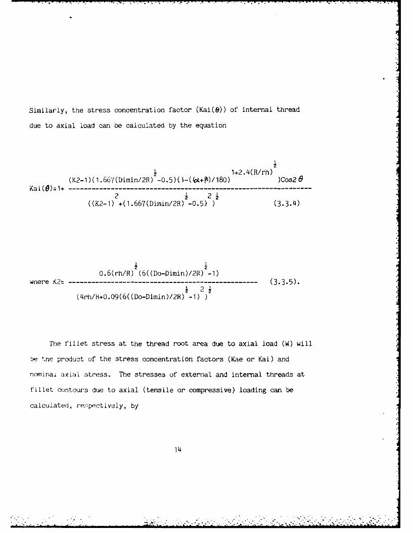
Similarly, the stress concentration factor (Kai(e)) of internal thread
due to axial load can be calculated by the equation
~1+2. 14(R/rh)(K2-1)(1.667(Dimin/2R) i-0.5)(1-(6L+4)/180) 124Rr))Cos2
Kai(tl)=1+ - - - - - - - - -- - - - - - - - - - - -- - - - - - - - - - -
2 2((K2-1) +(1.667(Dimin/2R) -0.5) ) (3.3.4)
0.6(rh/R) (6((Do-Dimin)/2R) -1)where K2= ------------------------------------------------- (3.3.5).
2(4rh/H+0.09(6((Do-Dimin)/2R) -1)
The fillet stress at the thread root area due to axial load (W) will
be the product of the stress concentration factors (Kae or Kai) and
nominai axial stress. The stresses of external and internal threads at
fiLlet contours due to axial (tensile or compressive) loading can be
calculated, re ;pectively, by
14
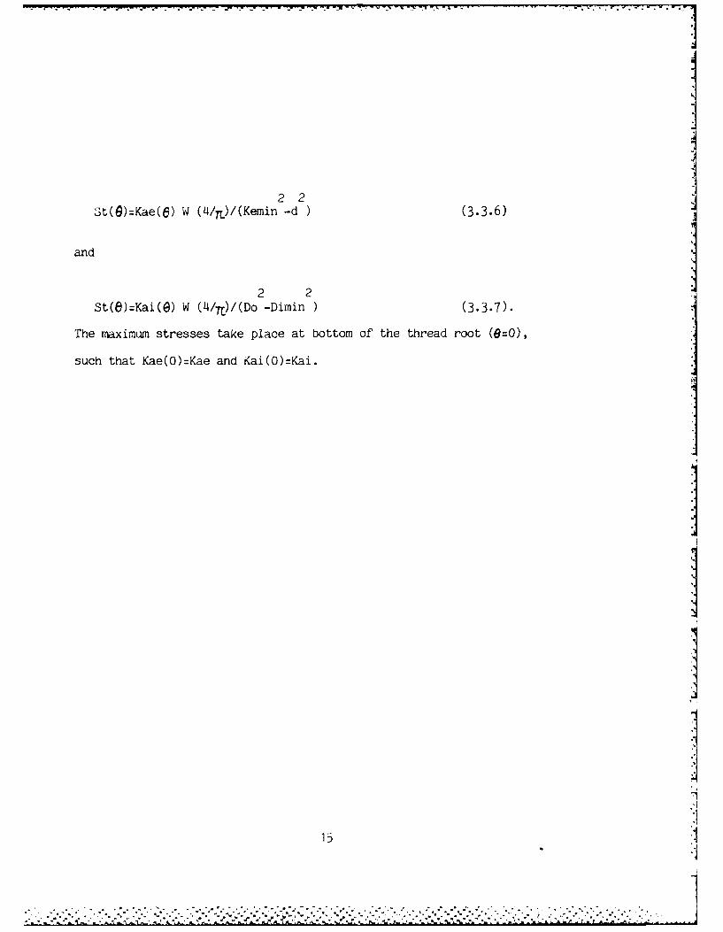
2 2St(g)=Kae(e) W (4/ 1 )/(Kemin -d )(3.3.6)
and2 21
The maximum stresses take place at bottom of the thread root (0=0),
such that Kae(O)=Kae and Kai(O)=Kai.
7I
I
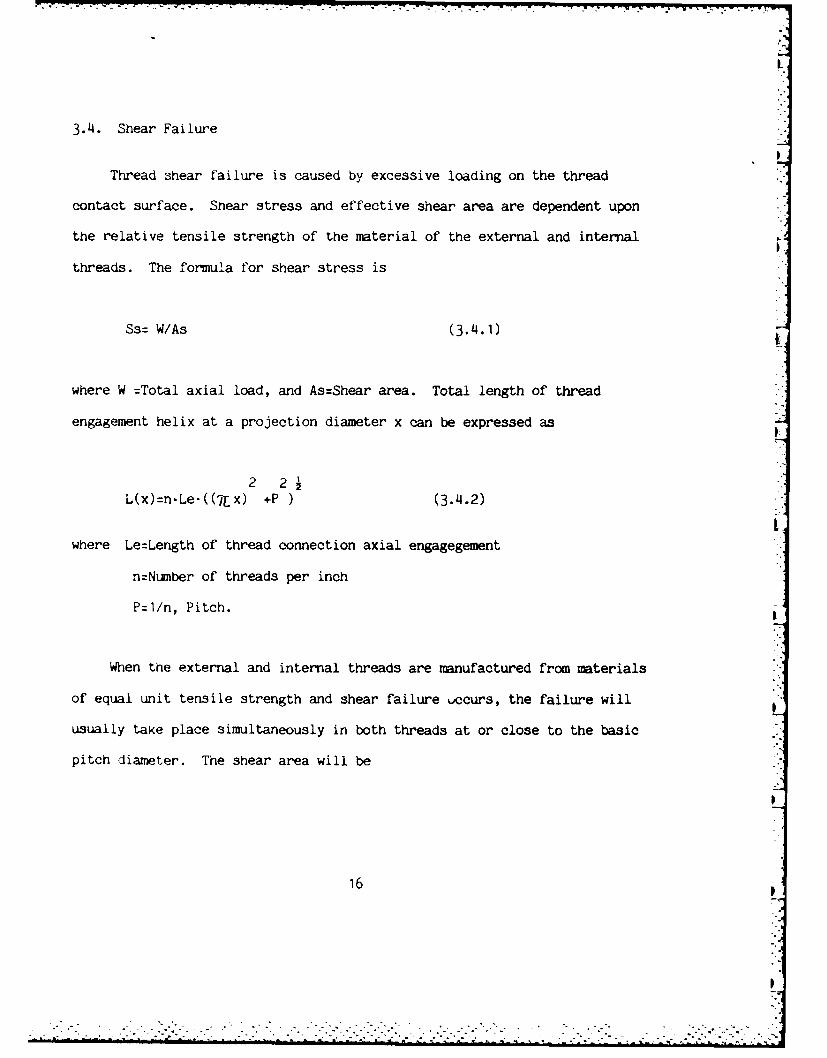
3.4. Shear Failure
Thread shear failure is caused by excessive loading on the thread
contact surface. Shear stress and effective shear area are dependent upon
the relative tensile strength of the material of the external and internal
threads. The formula for shear stress is
Ss= W/As (3.4.1)
where W =Total axial load, and As:Shear area. Total length of thread
engagement helix at a projection diameter x can be expressed as
2 2
L(x)-n-Le-((12x) +P ) (3.4.2)
where Le:Length of thread connection axial engagegement
n:Number of threads per inch
P=1/n, Pitch.
When the external and internal threads are manufactured from materials
of equal unit tensile strength and shear failure uccurs, the failure will
usually take place simultaneously in both threads at or close to the basic
pitch diameter. The shear area will be
1
16
"I
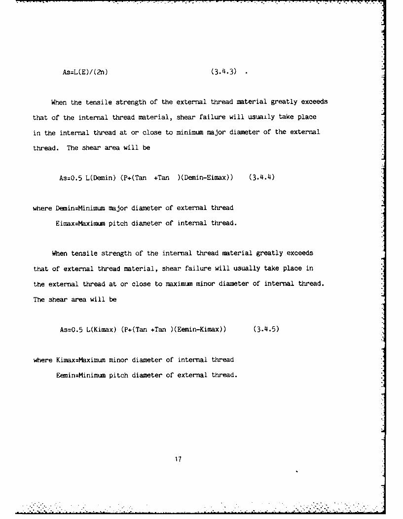
As=L(E)/(2n) (3.4.3)
When the tensile strength of the external thread material greatly exceeds
that of the internal thread material, shear failure will usuaily take place
in the internal thread at or close to minimum major diameter of the external
thread. The shear area will be
As=0.5 L(Demin) (P+(Tan +Tan )(Demin-Eimax)) (3.4.4)
where Deiin=Minimum major diameter of external thread
Eimax=Maximum pitch diameter of internal thread.
When tensile strength of the internal thread material greatly exceeds
that of external thread material, shear failure will usually take place in
the external thread at or close to maximum minor diameter of internal thread.
The shear area will be
As:O.5 L(Kimax) (P+(Tan +Tan )(Eemin-Kimax)) (3.4.5)
where Kimax:Maximum minor diameter of internal thread
Eemin=Minimum pitch diameter of external thread.
17
-- TO
3.5 Preload
Tightening and preload are recommended on some threaded connections
due to mechanical or structural design criteria, such as functional
and strength requirements. Statically, preloads improve locking effect
of the thread joint. For example, sufficient tensile preload is required
- in pipe flange bolts to overcome the longitudinal forces caused by the
pressure in the piping, so that the flanged connection does not leak.
A similiar problem is faced in tightening the nut on the cylinder head
of an engine block, so that the studs are all stressed equally and to a
"! tension that precludes leakage. If the threaded connection subjected
to cyclic loading, preload reduces the ratio of alternating stress (Sa)
to mean stress (Sm) and that improves the fatigue resistance of the
threaded connection, according to the fatigue fracture critertia in
Sa-Sm diagram.
Preload is recommended only for the material of threaded connections
with a stress-strain curve in which there is no clearly defined yield
point and progresses smoothly upward until fracture. For the described
material, proof load is defined as the maximum load applied to the
material without creating permanent deformation. For static loading
conditions, the torsional stress due to preload disappears after
.* tightening, if the strain of the material pass plastic yielding.
Therefore, the minimum preload is recommended as 90% of the proof load,
18
*-
and takes the form
Fp=0.9SyAt (3.5.1)
where Sy is the yield stress and At is the stress area of the threaded
connection. According to Federal Standard H-28 handbook, for steel parts
with tensile strength up to 180 ksi, the stress area is computed from
the following formula:
2
At= (Ir/4)(E-3h/4) (3.5.2)
where E is basic pitch diameter and h is the thread height. A threaded
connection subjected to slight movement3 will cause flattening of high
spots, paint or dirt and will relieve the torsional friction. Thus,
if the threaded connection does not fail during tightening, there is
a very good chance that it will never fail under static loading condition.
For cyclic loading condition, care must be taking for deciding direction
of preload. According to Juvinall (14), an overload causing yielding
produces residual stresses which are favorable to future overloads in the
same direction and unfavorable to future overloads in the opposite
direction. Apply preload only in the direction of anticipated service
loads.
Torque required to provide the specified preload for thread joint
19
is
T=KpFpD (3.5.3)
where Kp is torque coefficient, and D is major diameter of the threaded
connection. According to Shigley (15), Blake and Kurtz (16), no matter
what size and condition of lubrication of the threaded connection,
the torque coefficient Kp can be estimated as a constant 0.2, and
equation (3.5.3) becomes
T=O.2FpD (3.5.4)
The torque applied to the nut is used up in three ways. About 50% of
it is used to overcome the friction between the bearing face of the nut
and the member. About 40% of the applied torque is used to overcome
thread friction, and the balance produces the bolt tension. Only the last
two items contribute the torsion in the screw thread. During tightening
the torsional stresses of external and internal threads due to torque
become, respectively,
4 4Tpe=(0.16/idFpDemaxKemin/(Kemin -d ) (3.5.5)
and
20
.........................................................
4 4Tpi (0.16/16 FpDoDimin/ (Do -Dimin ) (3.5.6)
where Demax=Maximum major diameter of external thread
Kemin=Minimum minor diameter of external thread
Dimin:Minimum minor diameter of internal thread
Do:Equvalent outside diameter of internal thread
d:Inside (Hollow) diameter of external thread.
21
= .°. . . .
- - . - -, .- w - , " °.• t • . , . . .- -4-o- - . .- % i . - l -.- , - '
3.6 Thread Load and Heywood's Formula
The screw thread on each thread form can be considered as a short,
very wide cantilever, the width being the total length of the thread
along the helix. If the thread load is applied at a relatively great
distance from the thread root, the fillet stress at the thread root is
caused by bending moment. However, if the thread load is applied close to
the thread root, the nominal fillet stress can not be determined by merely
considering the effect of bending moment. The well-known Lewis formula (17)
calculating the maximum fillet stress for loaded projection, such as screw
and gear tooth, is based on a pure bending effect. The modified Lewis formula
proposed combined bending and compression effects to assess the maximum
fillet stress. But with introduction of stress concentration factor both
Lewis formula and modified Lewis formula can only correctly correlate well
with experimental results for a comparatively narrow range of shapes of loaded
projection.
From photoelastic data, Heywood (18), Kelly and Pedersen (19) introduced
load proximity and shear effects and proposed an empirical formula for estimating
fillet stress for various type of loaded projections. Heywood's empirical
formula correlates rather well, over a wide range of shapes of loaded projection,
with the experimental results from different researchers. Heywood observed
that, in case of screw thread, the maximum fillet stress occurred at approximately0
30 to the flank. The Heywood's empirical formula take the form:
22
~~~~~~~~~~.... ._ "., .. ,. ., .,,,.,...,. _ ..................... .**... .,
-q.b"
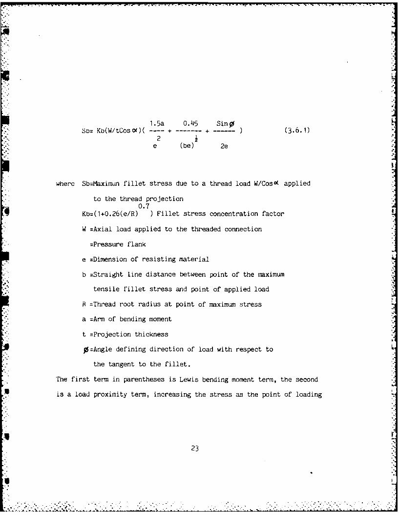
1.5a 0.45 Sin9So= KO(W/tCosX)( - - + - ) (3.6.1)
2e (be) 2e
where Sb=Maximun fillet stress due to a thread load W/Cos( applied
to the thread projection0.7
Kb=(1+O.26(e/R) ) Fillet stress concentration factor
W =Axial load applied to the threaded connection
=Pressure flank
e =Dimension of resisting material
b =Straight line distance between point of the maximum
tensile fillet stress and point of applied load
R =Thread root radius at point of maximum stress
a =Arm of bending moment
t =Projection thickness
O=Angle defining direction of load with respect to
the tangent to the fillet.
The first term in parentheses is Lewis bending moment term, the second
is a load proximity term, increasing the stress as the point of loading
23
U4
.
-. -.
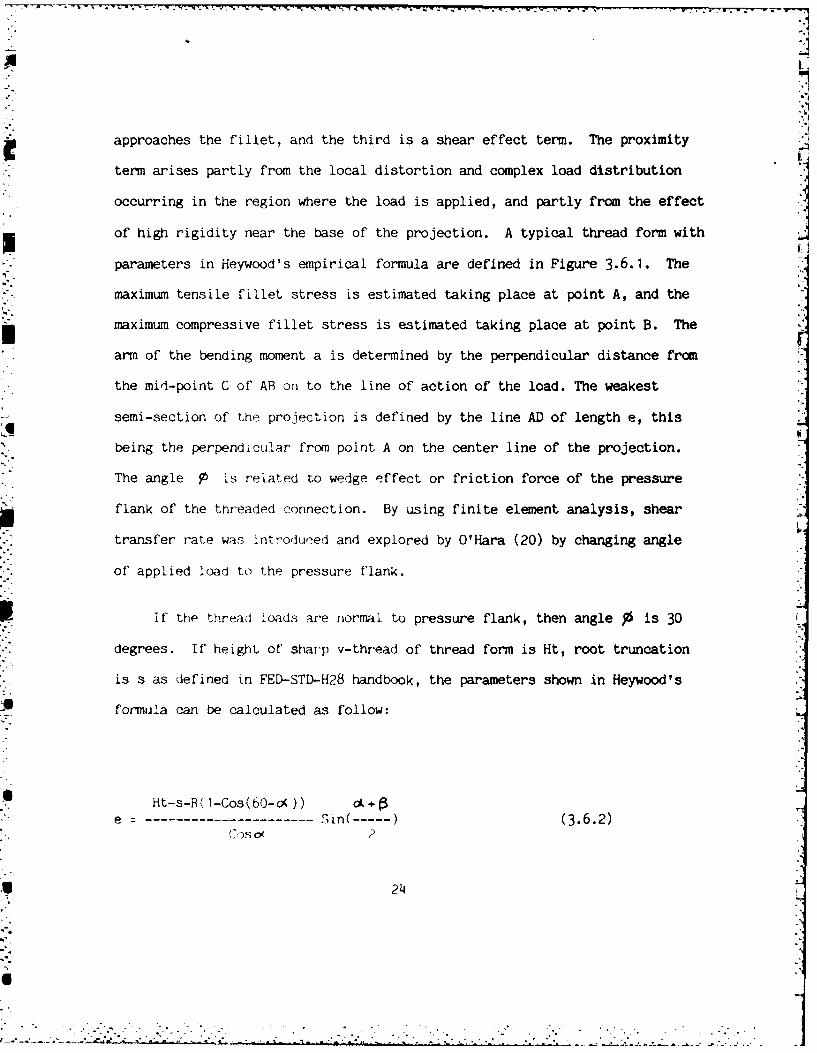
approaches the fillet, and the third is a shear effect term. The proximity
term arises partly from the local distortion and complex load distribution
occurring in the region where the load is applied, and partly from the effect
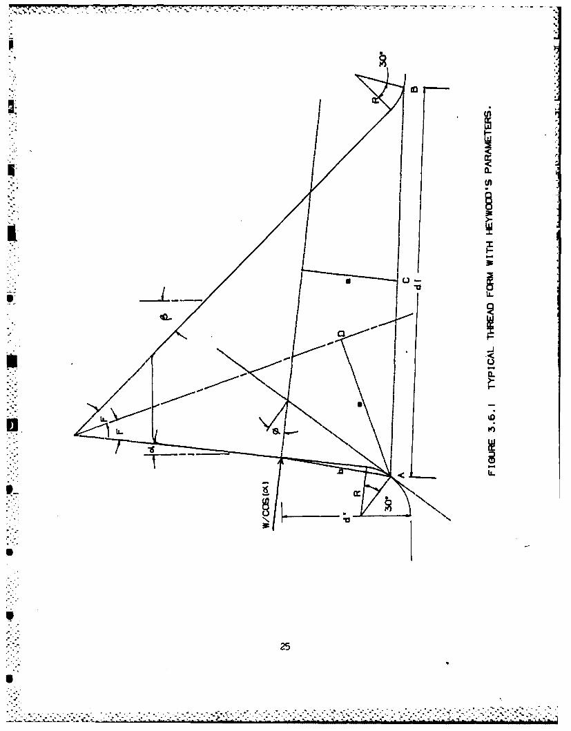
of high rigidity near the base of the projection. A typical thread form with
parameters in Heywood's empirical formula are defined in Figure 3.6.1. The
maximum tensile fillet stress is estimated taking place at point A, and the
maximum compressive fillet stress is estimated taking place at point B. The
arm of the bending moment a is determined by the perpendicular distance from
the mid-point C of AB on to the line of action of the load. The weakest
semi-section of the projection is defined by the line AD of length e, this
being the perpendicular from point A on the center line of the projection.
The angle O Is related to wedge effect or friction force of the pressure
flank of the threaded connection. By using finite element analysis, shear
transfer rate was introduced and explored by O'Hara (20) by changing angle
of applied load to the pressure flank.
If the threaA Loads are normal to pressure flank, then angle J is 30
degrees. If height of sharp v-thread of thread form is Ht, root truncation
is s as defined in FED-STD-H28 handbook, the parameters shown in Heywood's
J4 formula can be calculated as follow:
Ht-s-R(1-Cos(60-o()) ot3e ---------------------- Sin( - ) (3.6.2)
244
* IDISI* 0.
25i
d ' -R 1 l-Cos (60--)-
a = - Sin(cL+6) (dl/2-RTan(45-O(/2)+R Sin(60-o9) (3.6.3)Cos N
d'-R( l-CoF (60- ,) )
b = (3 .6.4)-1 d'Tan +RTan(45-o/2)-RSin(60 - 0 )
Cos(Tan ( -) )-d' -R( 1-Cos (60- 0))
where
dl: ml/cos(6) (3.6.5)
-11o=Tan (F-(Cos(60-j)-Cos(6-cK))/ml) (3.6.6)
ml: R(Tan(45- /2)+Tan(45-P/2)-Sin( 60- )-Sin(60- ) )
+P/2+(Tano(+Tan )(Eemin-Kemin)/2 (for external thread) (3.6.7)
or
m1= R(Tan(45-0'/2)+Tan(45-P/2)-Sin(60-cK)-Sin(6o0)) -
+P/2+(Tan* +Tan P)(Dimin-Eimin)/2 (for internal thread) (3.6.8)
and d' is the distance from point of applied load to minimum minor diameter
of the external thread (Kemin) or minimum major diameter of the internal
thread (Dimin). The parameter dl is the distance in between point A and _A
point B as shown in Figure 3.6.1.
26 .- °
S.
". ,
W-71
3.7 Pressure Flank Load Distribution
A pressure flank load distribution and application method was needed
for the mathematical thread joint model that would reflect real world
behavior and conform in principle to the leading accepted load distribution
theories of Sopwith and Heywood. In addition, this method was required to
handle loading of a variety of non-confe-ming thread conditions. The result-
ing method represents an approximation to actual thread loading phenomena and
does not attempt to quantify the effects of surface hardness and finish,I
friction, non-axial loading, non-parallel pressure flank surfaces, residual
stress, and other factors involved in the overall thread loading mechanism.
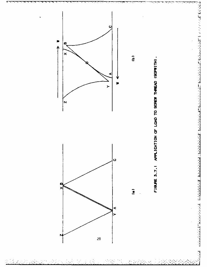
According to Sopwith (5), the screw thread on each component can be
considered as a short, very wide cantilever, the width being the total length
of the thread measured along the helix. The method of load application is
shown in Figure 3.7.1. The cantilevers ABC and XYZ in Figure 3.7.1a are
intially in contact over the their entire length, but when load W is applied,
the cantilevers deform as shown in Figure 3.7.1b. Sopwith contends that by
symmetry, the load will be concentrated at the center 0 of the two cantilevers;
the inner parts AO and OX will bend as shown, the unloaded outer parts
remaining straight and in line (BOY). Sopwith further asserts that, "In Ipractice the load will be distributed over a narrow band, such that the pres-
sure is of the order of the Brinnell hardness of the material, and even at
failure the width of this band will not exceed about 1/10th the length AB2
:1
ii- jI I
0
I
U
i
I
or XY (depth of engagement of thread) and may be taken as concentrated. In
the screw thread case, the mean width of the two 'cantilevers' is slightly
different, and the load will be concentrated not at mid-depth, but very
slightly nearer the root of the male thread." To condense Sopwith's analysis,
the thread loading is a point load (possibly a small distribution) acting very
near the center of the thread depth.
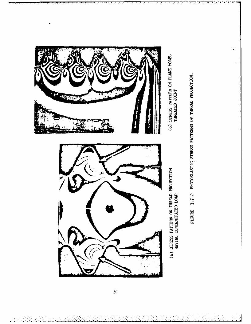
Heywood (18), presents two-dimensional photoelastic analysis of thread
joints under single point loads having different orientations and simulated
thread-to-thread contact loads. In comparing the two photographs of Figure
3.7.2, they both exhibit some similar tendencies in the relative locations
and magnitude of stresses, except at the contact surfaces where some obvious
differences are noted. The interference bands indicating the stress contours
in Figure 3.7.2a show a concentrated high stress from which circular bands
emulate. However, in Figure 3.7.2b the simulated thread-to-thread contact
shows an elongated stress contour roughly parallel to the pressure flank
surface, a marked departure from the point load photograph. The contour
appears to be a slightly lop-sided parabolic shape with the axis located
approximately at the center of the thread depth.
Before proceeding with developing a non-uniform load distribution, the
uniform load distribution using seven point loads proposed by O'Hara (20)
was studied for possible application to this effort. In our opinion, the
29
.4
IMF
300
* . . . . •w---w--. x~ .'-- . - '
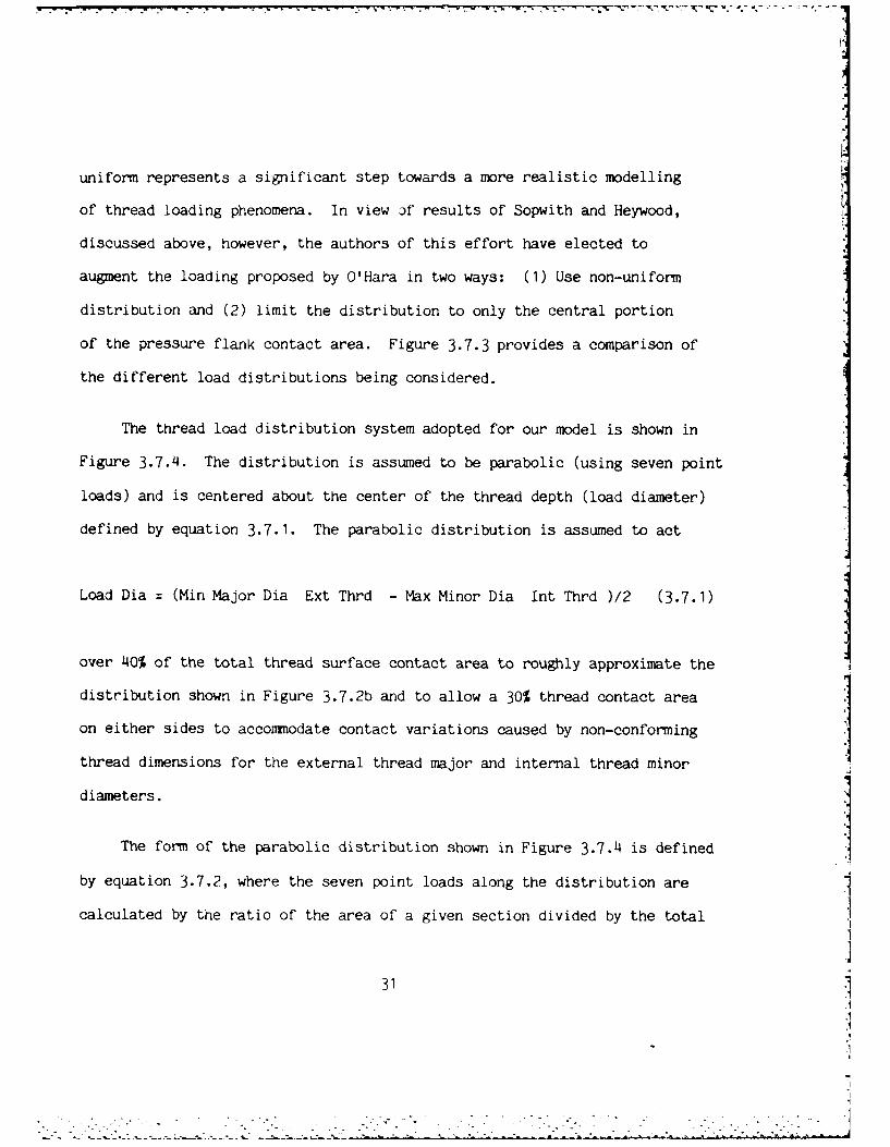
uniform represents a significant step towards a more realistic modelling
of thread loading phenomena. In view Df results of Sopwith and Heywood,
discussed above, however, the authors of this effort have elected to
augment the loading proposed by O'Hara in two ways: (1) Use non-uniform
distribution and (2) limit the distribution to only the central portion
of the pressure flank contact area. Figure 3.7.3 provides a comparison of
the different load distributions being considered.
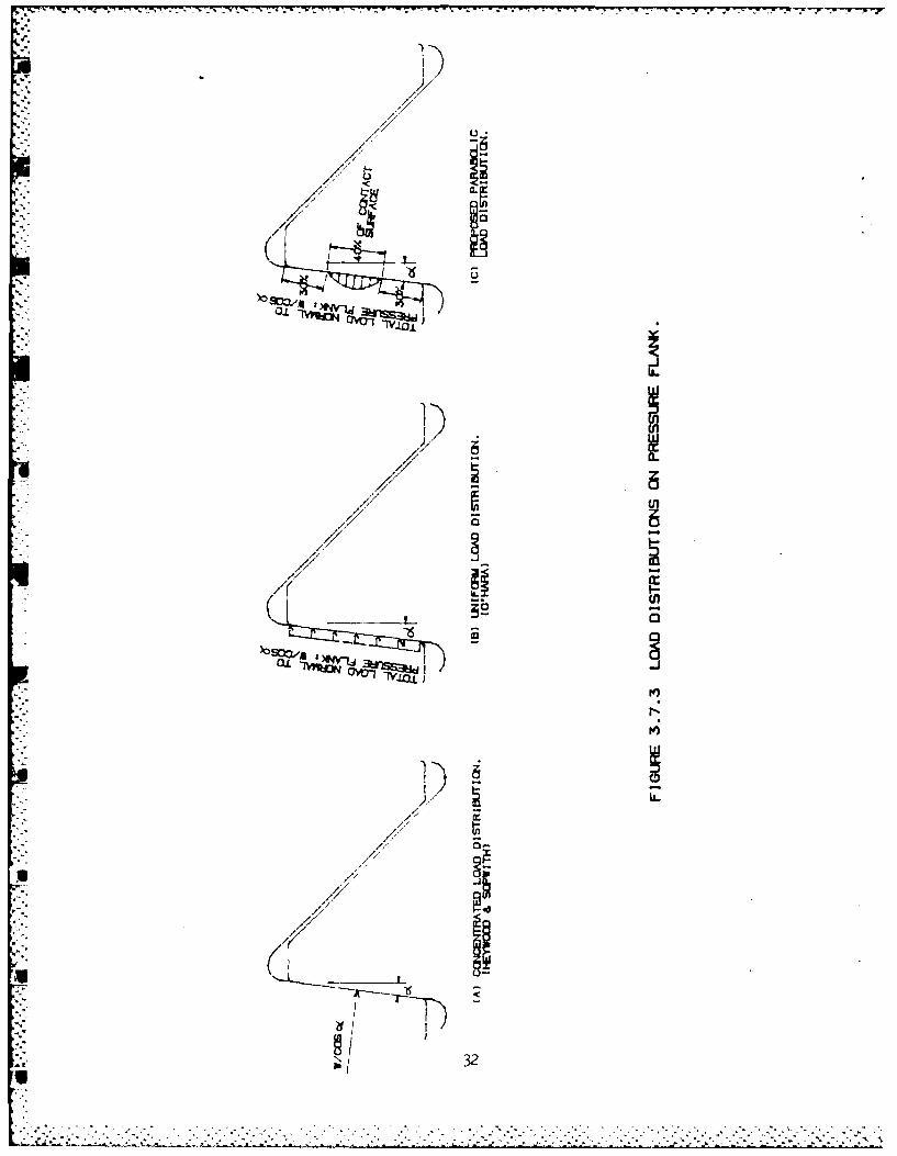
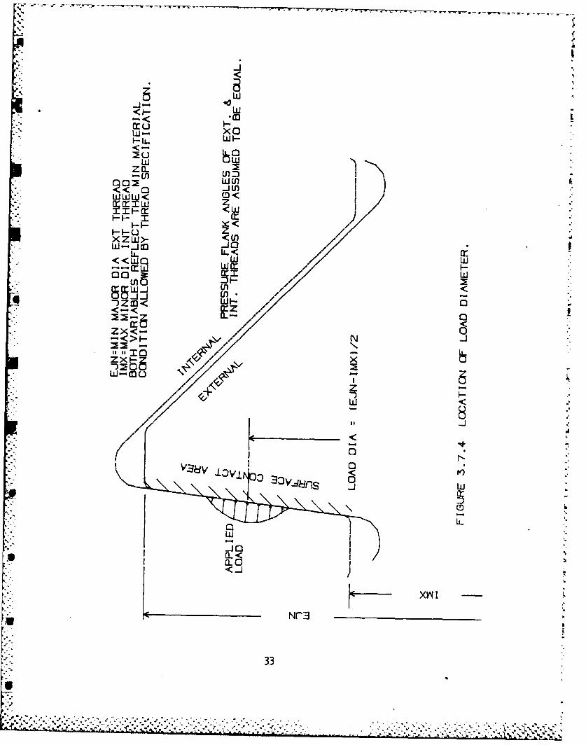
The thread load distribution system adopted for our model is shown in
Figure 3.7.4. The distribution is assumed to be parabolic (using seven point
loads) and is centered about the center of the thread depth (load diameter)
defined by equation 3.7.1. The parabolic distribution is assumed to act
Load Dia = (Min Major Dia Ext Thrd - Max Minor Dia Int Thrd )/2 (3.7.1)
over 40% of the total thread surface contact area to roughly approximate the
distribution shown in Figure 3.7.2b and to allow a 30% thread contact area
on either sides to accommodate contact variations caused by non-conforming
thread dimensions for the external thread major and internal thread minor
diameters.
The form of the parabolic distribution shown in Figure 3.7.4 is defined
by equation 3.7.2, where the seven point loads along the distribution are
calculated by the ratio of the area of a given section divided by the total
31.1A
soo/a
O7<
P../u
/ U)
21
- - '- 2~ ' ~ r r. - - . e . . r--r w -.- <
W- XW
LWW
«0 CD<
SL«om WW
* ~ < 00 -U.
IIIm zoZ- Z m
&,' <
0 -';-. -
W~t FW
C33J0 It:
IZn QW <
3<>F- N -
M 3311J5
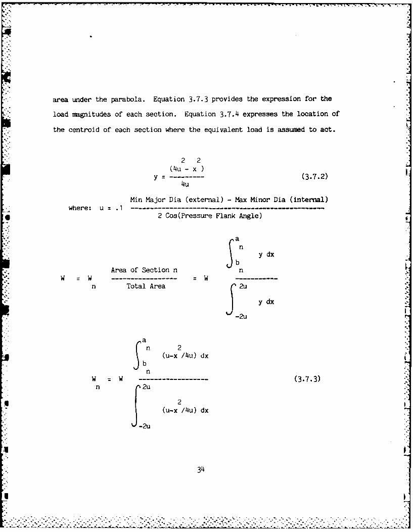
area under the parabola. Equation 3.7.3 provides the expression for the
load magnitudes of each section. Equation 3.7.14 expresses the location of
the centroid of each section where the equivalent load is assumed to act.
2 2(1u -x
y (3.7.2)4u
Min Major Dia (external) -Max Minor Dia (internal)where: u .1 --------------------------------------------
*2 Cos(Pressure Flank Angle) W
Area f Setionn S n ydn
W =W- ---------------- = W ------
n Total Area C2u
-2u
(u-x/1Au) dx
nW = W -- - - - - - - - -(3.7.3)n 2* 3 (u-x /4u) dx
314
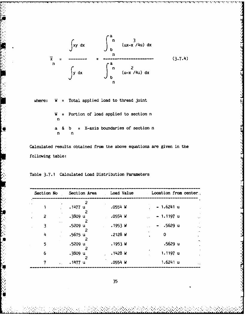
dx (ux-x Au) dx
nx -- - - -- - - -- - - - - - (3.7.4)nadx (u-x /Au) dx
where: W Total applied load to thread joint
W Portion of load applied to section nn
a & b = X-axis boundaries of section nn n
Calculated results obtained from the above equations are given in the
following table:
Table 3.7.1 Calculated Load Distribution Parameters
-------------------------------------------------------- -- - - p
Section No Section Area Load Value Location from center,
21 .1477 u .0554 W - 1.6241 u
22 .3809 u .0554 W - 1.1197 u
23 .5209 u .1953 W - .5629 u
24 .5675 u .2128 W 0
25 .5209 u .1953 W .5629 u
26 .3809 u .1428 W 1.1197 u
27 .1477 u .0554 W 1.6241 u- - -- ---------------------------------------------
35
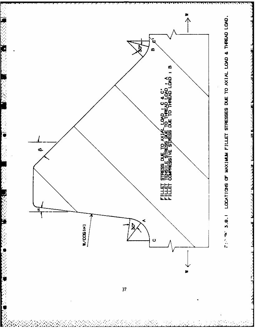
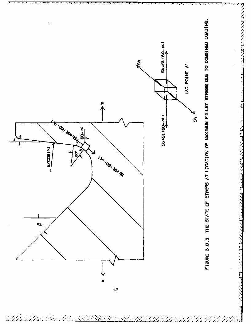
3.8 Combined Loading
Both axial loads and thread loads produce fillet stresses in the thread
root area. As indicated in Figure 3.8.1, the axial loads cause concentration
of stress at the bottom of thread roots (points c and c'); while thread loads
cause stress concentration at approximately 30 degrees to pressure flank
(point A), and compressive stress at approximately 30 degrees to clearance
flank (point B). The magnitude of tensile fillet stress is usually much
larger than that of compressive fillet stress. The angle between fillet
stress due to axial load and tensile fillet stress is (60- 0'), where co( is
the pressure flank angle in degrees. Combined loading will produce a maximum
fillet stress which is considered a major factor of thread failure.
Notched parts subjected to bending or axial loads often experience a
biaxial stress at the surface of the notch. A threaded connection in
tension sees a tangential or a circumferential tensile stress in the notch,
in addition to the primary axial stress. Peterson (21) has considered the
influence of this biaxial stress factor, as assessed by the distortion
energy theory of failure. Addition of the primary and secondary principal
stresses, which have the same sign, reduces the energy of distortion.
The biaxial effect is a favorable one which lowers the effective stress
concentration factor to an estimated maximum of' 15% lower than the regular
stress concentration factor.
36
U*-*.. . .
-.P -7
ct4o
CalJ
370
Tangential (hoop) stress at the thread root area should be included in
the thread stress analysis, as in the case of the cannon breech mechanism
where the threaded connections are subjected to internal pressure. Consider
a thick wall cylinder with inside radius (ri) and outside radius (ro), which
is subjected to an internal pressure (pi). The radial stress (Sr) and tangen-
tial stress (Sh) can be expressed as
2
Sr(r)=Kh (1-(ro/ri)) (3.8.1)
* . and
2Sh(r):Kh (1+(ro/ri)) (3.8.2)
2 2 2where Kh=(pi)(ri) /((ro) -(ri) ), r is the radius varying from ri to ro.
At outside surface of the thick wall cylinder r=ro, the radius stress
and tangential stress become
Sr(ro):O (3.8.3)
and
2 2 2Sh(ro)=2(pi)(ri) /((ro) -(ri) ) (3.8.4).
The tangential stress at external thread root area can be estimated by
the equation
2 2 2Sh:2(pi)(d) /((Kemin) -d ) (3.8.5)
38
.IS.
where d is hollow diameter and Kemin is minimum minor diameter of the
external thread. If preload is applied on the threaded connection,
the tangential stress for internal thread at the thread root area can
be estimated by simulating the threaded connection as concentric
cylinders with an interference fit. Since the loading condition of
internal pressure is two-dimensional, only plane stresses will be
involved. The tangential stress can be superimposed with fillet stres-
ses due to axial load and thread load.
The actual magnitudes of combined stresses due to axial load, thread
load and internal pressure at any point along the thread root boundary
are extremely difficult to assess for they depend on the complicated
distortions and strains occurring in the two threaded members. However,
photoelastic data show that the tensile fillet stress is the dominating
component in the combined loading effects. The maximum fillet stress
is observed in between bottom of the thread root and point A, 30 degrees
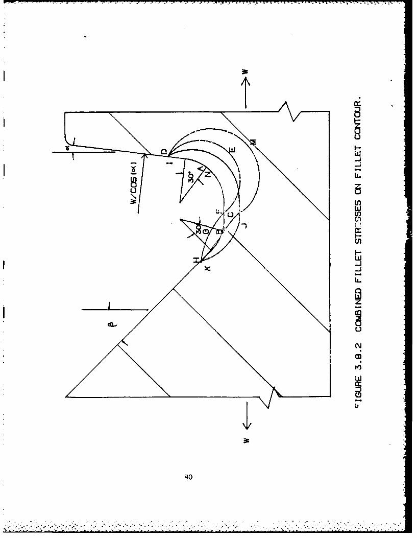
to pressure flank, and very close to point A. Figure 3.8.2 shows the
combined effect of fillet stresses. The dotted line DEF represents the
distribution of tensile fillet stress due to thread load (along the
bounuary of thiread root) and has its maximum value at point A. The
dotted line FGH represents the distribution of compressive fillet stress
due to thread load and has its maximum value in magnitude at point B.
Similarly, dotted line IJK represents distribution of tensile fillet
39
H',
K -•9"9." .. . j j . **..."," .- '*' ",- -" * ,I
w7
w-J
It
UR
w
I-
w-J
40J
stress due to axial load having its maximum value at point C. By adding
the three stresses at points along the thread root boundary, an estimate
is obtained for the stress distribution due to the combined effect,
which is represented by chain dotted line HMD having a maximum value
at point N and very close to point A. For simplicity, it is assumed
that -he maximum value of the combined effect takes place at point A.
The maximum combined stress, obviously, is not equal to the algebraic
sum of maximum values due to separately applied loads.
On the boundary of the thread root, stresses normal to fillet contours
are zero, and there are no shear stresses on free contour surface.
Therefore, the combined fillet stress at point A is a principal stress
which is tangent to the fillet contour, and takes the form
Sc=Sb+St(60-oQ (3.8.6)
where Sb is the maximum fillet stress due to thread load and St(60-)
is the fillet stress due to axial load at point A. Including tangential
(hoop) stress Sh, the state stress at point A is shown in Figure 3.8.3.
The nydrostatic tension and pure shear on octahedral plane can be
written, respectively, asA
Soct=(1/3)(Sb+St(60-o)+Sh) (3.8.7)
and
Toct=(1/3)(Sb+St(60-cO-Sh) (3.8.8)
4 1
. .7
393
Ilia~
a "'v
42,
Under the static loading condition, the safety factors of the threaded
connection due to triaxial tensile fillet stress are defined as
Ny=Sy/Soct (3.8.9)
and
Nu=Su/Soct (3.8.10)
wnere Ny and Nu are safety factors referring to yield stress and ultimate
strength, respectively. Similarly, if the maximum distortion energy
theory is applied, safety factors of the threaded connection due to
triaxial shear fillet stress are defined as
Ny=O.577Sy/Toct (3.8.11)
and
Nu=0.577Su/Toct (3.8.12)
43
i.-.
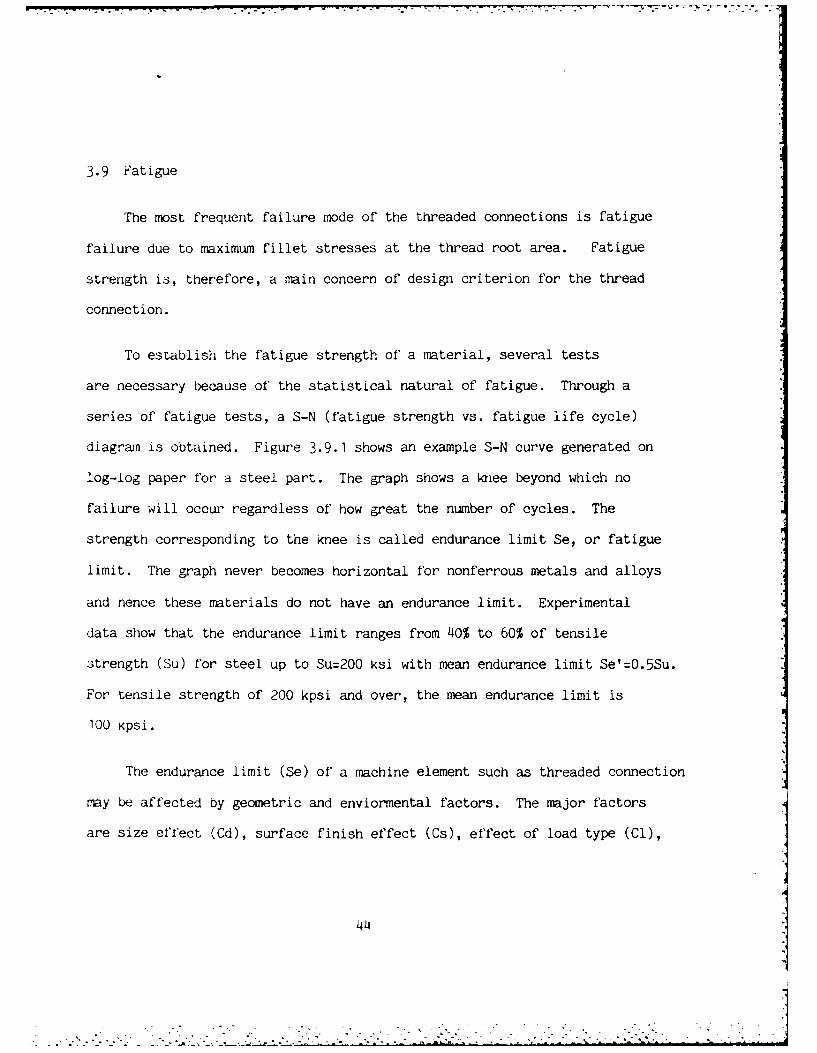
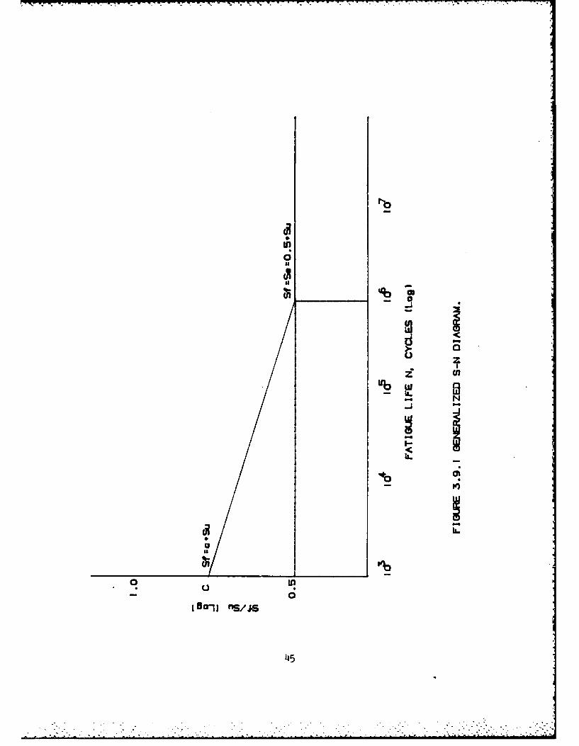
3.9 Fatigue
The most frequent failure mode of the threaded connections is fatigue
failure due to maximum fillet stresses at the thread root area. Fatigue
strength is, therefore, a main concern of design criterion for the thread
connection.
To establish the fatigue strength of a material, several tests
are necessary because of the statistical natural of fatigue. Through a
series of fatigue tests, a S-N (fatigue strength vs. fatigue life cycle)
diagram is obtained. Figure 3.9.1 shows an example S-N curve generated on
log-log paper for a steel part. The graph shows a knee beyond which no
failure will occur regardless of how great the number of cycles. The
strength corresponding to the knee is called endurance limit Se, or fatigue
limit. The graph never becomes horizontal for nonferrous metals and alloys
and hence these materials do not have an endurance limit. Experimental
data show that the endurance limit ranges from 40% to 60% of tensile
strength (Su) for steel up to Su=200 ksi with mean endurance limit Se'=O.5Su.
For tensile strength of 200 kpsi and over, the mean endurance limit is
100 kpsi.
The endurance limit (Se) of a machine element such as threaded connection
may be affected by geometric and enviormental factors. The major factors
are size effect (Cd), surface finish effect (Cs), effect of load type (Cl),
44 W-L I
NO
00
- 0
L)L
00
45
.- .. - . ,. .- _ - - . .. . , . - " - -, - . . '-- . . . - - -
modifying factor due to fatigue stress concentration (Ck), temperature effect
- . (Ct) and reliability factor (Cr). The modified endurance limit may be
written as
Se=CdCsClCkCtCrSe' (3.9.1).
The size effect is generally believed to be related to the stress gradient.
For bending and torsion Cd is selected as follow:
Cd=1 D<=O. 4"
Cd=0.85 0.4" (D (=2"
Cd=0.75 D >2" (3.9.2)
where D is major diameter of the threaded connection. And for axial load Cd=1.
Surface finish of a part may affect its endurance limit in three ways:
(1) by introducing stress concentration resulting from surface roughness,
(2) by altering the physical properties of the surface layer of the material,
e.g., an as-forged surface is not only rough but also decarburized, and
the decarburization decreases the strength of the surface layer, and (3)
* by introducing residual stresses, e.g., grinding operations often leave the
surface layer in residual tension and thereby reduce its ability to withstand
reversed loading. The surface finish effect Cs is defined as the ratio
between the endurance limit obtained with arbitrary surface finish and that
obtained with the standard Moore mirror-polished finish as shown in Figure
3.9.2.
4
?" . . .. . . . . . . . . . . ,4 . . . . . . . . . .
0
W<
m-
CD-____ ___U)* I -w x
U g
T- WDMo
___ _ _ LEcl
I-i-I-N
CD
0 a a a a a aJ.3~OIVA HSINIA 2Z3v.ifs
47
......................................................
6
According to Juvinall (14i), the endurance limit at 10 -cycle strength
for various load types may, in absence of specific test data, be approximated
by multiplying "the standard mean endurance limit Se' by the following load
constants (Cl):
Reversed or rotating bending: C1=1.0
Reversed axial loads: Cl=O.9 without bending,
01=0.6 to 0.85 with indeterminate bending
Reversed torsion: 01:0.58 ductile metals,
01=0.8 cast iron (and mst brittle materials).
Stress concentration is a highly localized effect. The high stresses
actually exist in only very small region in the vicinity of the discontinuity
* such as fillet, notch and crack. In the case of ductile materials the first
load applied to the member will cause yielding at the discor'inuity which
relieves the stress concentration. Thus when the parts are made of ductile
materials and the loads are static, it isn't necessary to use a stress
concentration factor. However, when parts are made of brittle materials
or when they are subject to fatigue loading ,then the stress concentration
to be considered. Fatigue stress concentration factor Kf is defined as a
ratio between endurance limit of notch free specimen and endurance limit
of notched specimen. This factor can be expressed in terms of notch sensitivity
q and stress concentration factor Kt, such that
48
. . . .°.
Kf= 1+q(Kt-1) (3.9.3)
where 0 =q =1. If q=O, Kf1, the material has no sensitivity to notches
at all. If q=1, Kf=Kt, the material has full sensitivity to notches.
Figure 3.9.3, provided by R. E. Peterson (21), shows a family of curves
of notch sensitivity q with respect to notch radius r for various steel
tensile strengths. For a typical unified and American standard thread
steel bolt subjected to bending or axial loading, the fatigue stress
concentration factor Kf is estimated as follow:
Annealed (less than 200 Bhn): Kf=2.2 (rolled), Kf=2.8 (machined)
Quenched and drawn(over 200 Bhn): Kf=3.0 (rolled), Kf=3.8 (machined).
The modifying factor for stress concentration is defined as Ck=1/Kf. According
to Heywood (13), fatigue stress concentration factor for finite life (Kf')
ranges from 1 to Kf, where (Kf'-1)/(Kf-1) is fairly linearly proportional to
ultimate tensile strength (Su) as shown in Figure 3.9.4. In this report, the
estimated safety factor for simple cyclic loading at various finite life
cycles (N), Kf' is assumed to be linearly proportional to Log(N).
The temperature effect is considered when the machine elements are operated
under high temperature enviroment. For ferrous metals the temperature effect
(Ct) is estimated to be:
0Ct:620/(460+T) When T >160 F
0
Ct=1 When T< =160 F (3.9.4).
49
S°" •
H-* - - - -
d
4
I
- - I1=- ~~~~0 I20
U Ii------------------ - U ~ cS
___ 0 C8
5ii i a I-
S i- - - - a - - -I
0I')
SS
Ii.
~00 6 U U- * U 4 1 N - 0
S S
b AI.IAI±ISI2S H~LCNK -oo d 00 a
50
U
. . . -
8 6z
I-i
X-Jlww
0 -z.a inw C-W
Go WW
0 g...
I JA)
51
a
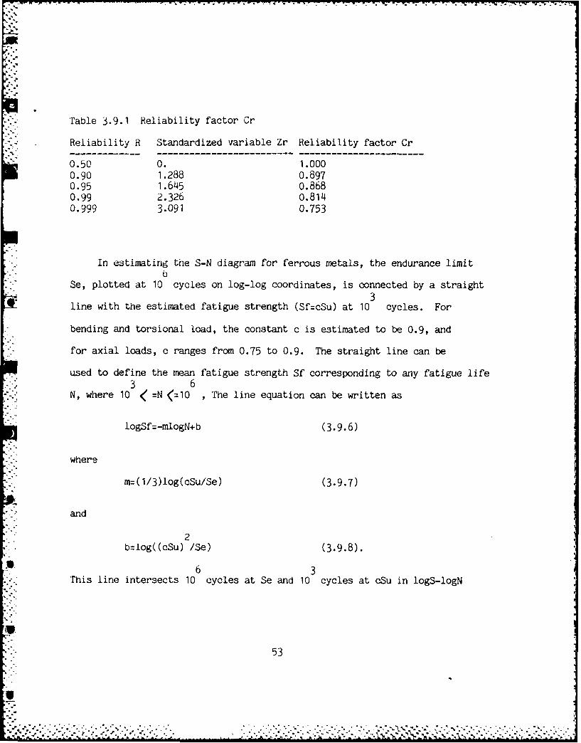
Table 3.9.1 Reliability factor Cr
Reliability R Standardized variable Zr Reliability factor Cr
0.50 0. 1.0000.90 1.288 0.8970.95 1.645 0.8680.99 2.326 0.8140.999 3.091 0.753
In estimating the S-N diagram for ferrous metals, the endurance limitb
Se, plotted at 10 cycles on log-log coordinates, is connected by a straight3
line with the estimated fatigue strength (Sf=cSu) at 10 cycles. For
bending and torsional load, the constant c is estimated to be 0.9, and
for axial loads, c ranges from 0.75 to 0.9. The straight line can be
used to define the mean fatigue strength Sf corresponding to any fatigue life3 6
N, where 10 < =N <=10 , The line equation can be written as
logSf=-mlogN+b (3.9.6)
where
m=(I/3)log(cSu/Se) (3.9.7)
and
2b=log((cSu) /Se) (3.9.8).
6 3This line intersects 10 cycles at Se and 10 cycles at cSu in logS-logN
53
"9 j ' ' ' ' ... .° ' " ' ° . " • . " . . "' ' '" ." , ' ' , " . ,, ' ., -' ' 2 , ' - - -" , ,
- --.-..--- - - ..
curve. When Su and Se are given, parameters m and b can be solved. Then if
fatigue life N is given, the corresponding fatigue strength Sf can be
calculated through the following relation:
b m 3 6Sf=10 /N , 10 <=N<=10 (3.9.9).
Alternatively, if the fatigue strength Sf is given, the fatigue life N
can be found as
I -~
b/m 1/m 3 6N=10 /Sf , 10 <:N<=I0 (3.9.10).
4 For the loading history, fluctuating stresses are presented in terms of
maximum stress Smax (or Tmax for torsion), minimum stress Smiin (or Trin),
mean stress Sm (or Tm), alternating stress Sa (or Ta) and prestress Sp (or Tp).
The mean stress and alternating stress can be expressed as
Sm=Sp+(Smax+Smin)/2 (3.9.11)
and
Sa=(Smax-Smin)/2 (3.9.12).
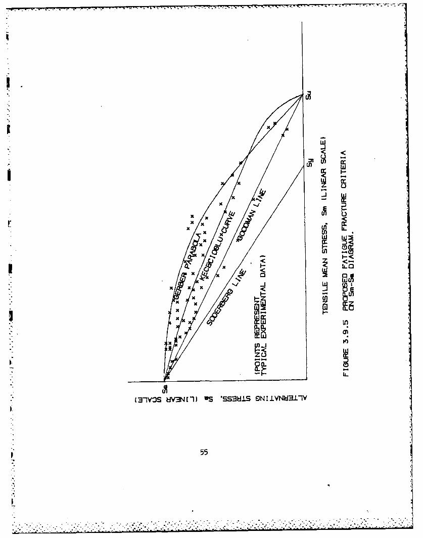
A few criteria for fatigue fracture are presented in the literatures
such as Soderberg line, Goodman line, Gerber parabola, Sine octahedral
approach and Kececioglu curve. Figure 3.9.5 shows a typical Sa-Sm diagram
- with test data and various fatigue fracture criteria with respect to the
I endurance limit. The Sine octahedral approach cannot be illustrated except
for special cases. These proposals, each having their particular degree
54
4J
. -. -. -. . . . .. ... .. . -- . - . . . . . .. .. . • .2" A t .. .-.. . . . . . . .
w~< <
J wm
x xxw w
XEX
O(LL
(-1VZ3S 8V3N 1-11 8S 'SS3UlS SN I VN8311V
p 55
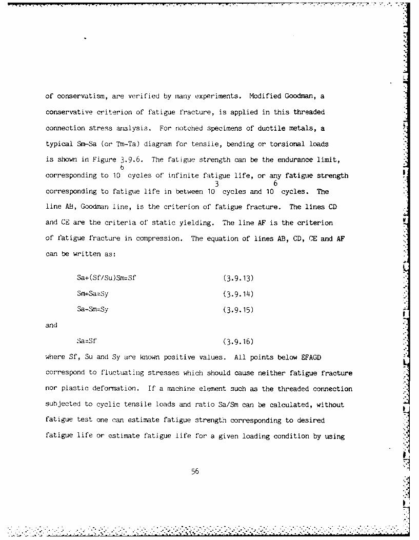
of conservatism, are verified by many experiments. Modified Goodman, a
conservative criterion of fatigue fracture, is applied in this threaded
connection stress analysis. For notched specimens of ductile metals, a
typical Sm-Sa (or Tm-Ta) diagram for tensile, bending or torsional loads %
is shown in Figure 3.9.6. The fatigue strength can be the endurance limit,6
corresponding to 10 cycles of infinite fatigue life, or any fatigue strength3 6
corresponding to fatigue life in between 10 cycles and 10 cycles. The
line AB, Goodman line, is the criterion of fatigue fracture. The lines CD
and CE are the criteria of static yielding. The line AF is the criterion W
of fatigue fracture in compression. The equation of lines AB, CD, CE and AF
can be written as:
Sa+(Sf/Su)Sm=Sf (3.9.13)
Sm+Sa-Sy (3.9.114)
Sa-Sm:Sy (3.9•15)
and
Sa=Sf (3.9.16)
where Sf, Su and Sy are known positive values. All points below EFAGD
correspond to fluctuating stresses which should cause neither fatigue fracture
nor plastic deformation. If a machine element such as the threaded connection
subjected to cyclic tensile loads and ratio Sa/Sm can be calculated, without
fatigue test one can estimate fatigue strength corresponding to desired
fatigue life or estimate fatigue life for a given loading condition by using
56
,:-
JF)
CD <
F-L-)0
ui <(-) <u'e es~lis (n
~iNI.N~LIV 0 r w<
z L)
7-. E
I',
Ii-
U)
57
--------------------- ,.... A6
L• .1
I.:
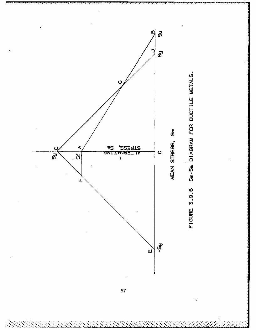
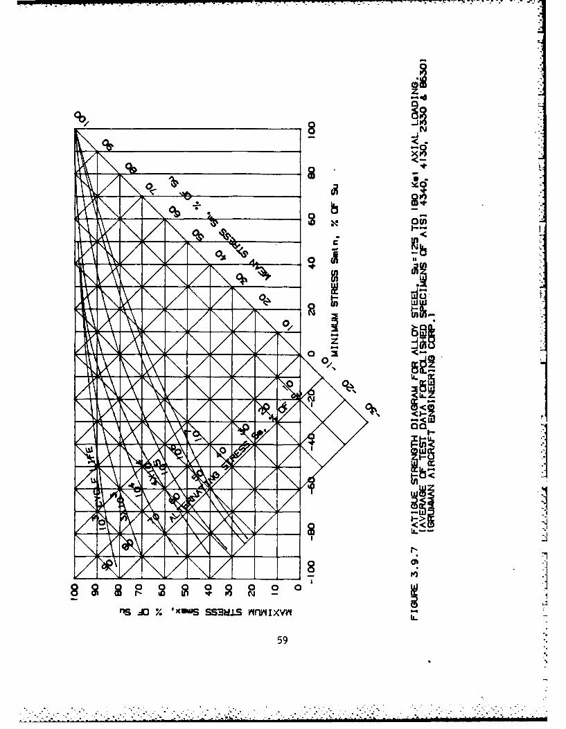
Figures 3.9.1 or 3.9.6. Figure 3.9.7 shows a experimental fatigue strength
diagram for alloy steel with Su=125 to 180 kpsi under axial loading using
Sm-Sa as well as Smax-Smin coordinates. The curves are generated by Grumman
Aircraft Engineering Corp., and applicable to alloy steel as AISI 4340, 4130,3
2330 and 8630 etc. The diagram shows that the fatigue strength at 10 cycles
is about 84% of the ultimate strength. This diagram and fatigue factor of size
effect (Cd), surface finish effect (Cf), load type effect (Cl), modifying factor
due to fatigue stress concentration (Ck), temperature effect (Ct) and reliability
factor (Cr) will be used in the program to estimate the safety factor of the
threaded joint under a simple cyclic loading condition at various fatigue life
cycles.
From Section 3.8, combined loading, the elements on the fillet contour have
two stress components which are the hoop stress (Sh) and the combined fillet stress
due to axial load and thread load (Sc). Both stresses Sh and Sc may have both I
mean and aiternating components (Shm, Sha, Scm and Sca). By using distortion
energy theory, the mean and alternating von Mises stresses are defined as:
S'm:(Shm -ShmScm+Scm ) (3.9.17)
and
22S'a=(Sha -ShaSca+Sa ) (3.9.18) .
58 §1
*,a . .....e- ............ z~dr~.ia nni|i ......... ....... . , ..... ... .. :
01z
-JN
______ I
WL
cn
0,0
flS Xd % v(UU SSB.LS fM I lXVII
59
These two stress components may then be applied to S'm-S'a diagram and
fatigue criterion such as modified Goodman criterion to estimate fatigue
strength or fatigue life.
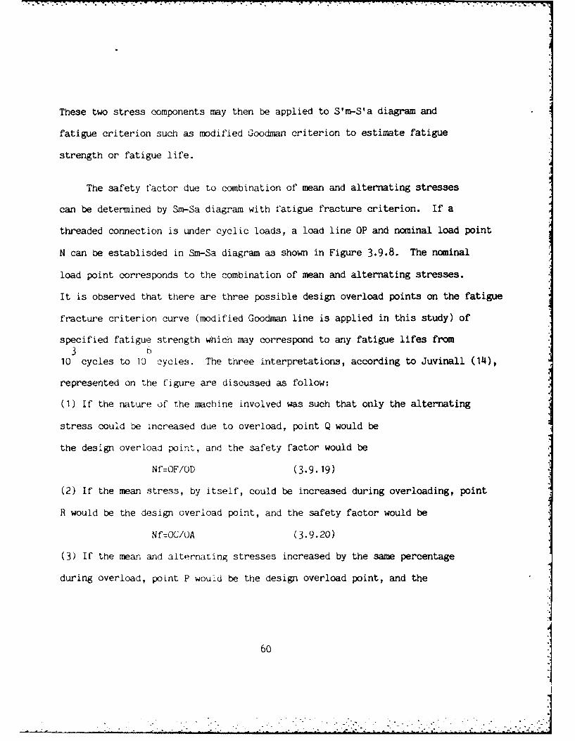
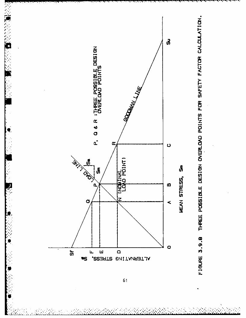
The safety factor due to combination of mean and alternating stresses
can be determined by Sm-Sa diagram with fatigue fracture criterion. If a
threaded connection is under cyclic loads, a load line OP and nominal load point
N can be establisded in Sm-Sa diagram as shown in Figure 3.9.8. The nominal
load point corresponds to the combination of mean and alternating stresses.
It is observed that there are three possible design overload points on the fatigue
fracture criterion curve (modified Goodman line is applied in this study) of
specified fatigue strength which may correspond to any fatigue lifes from3
10 cycles to 10 cycles. The three interpretations, according to Juvinall (14),
represented on the figure are discussed as follow:
(1) If the nature of the machine involved was such that only the alternating
stress could be increased due to overload, point Q would be
the design overload point, and the safety factor would be
Nf=OF/OD (3.9.19)
(2) If the mean stress, by itself, could be increased during overloading, point
R would be the design overload point, and the safety factor would be
Nf:OC/OA (3.9.20)
(3) If the mean and alternating stresses increased by the same percentage
during overload, point P would be the design overload point, and the
60
ptl
w4aDC
U)WI--iJz
d2 0.
Z u l
IN I
0
-10
U)Q )
US 'SS RS ON IlYN31V W
61
-7-771--7- -. -.r
safety factor would be
Nf=OP/ON=OE/OD:OB/OA (3.9.21)
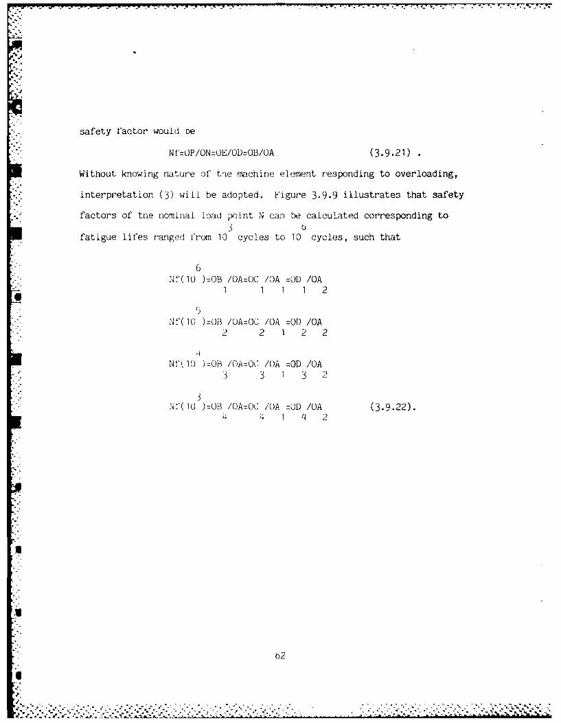
Without knowing nature of the machine element responding to overloading,
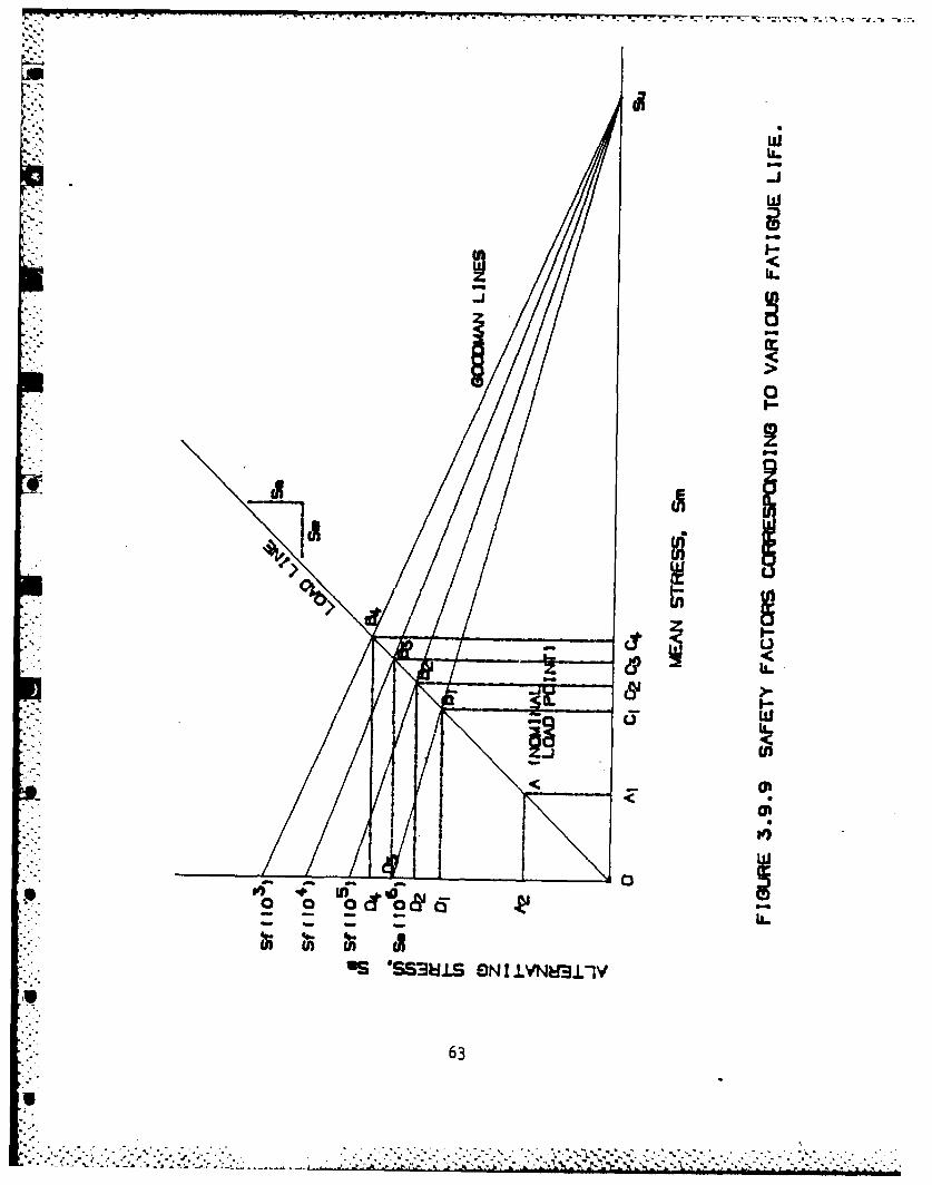
interpretation (3) will be adopted. Figure 3.9.9 illustrates that safety
. factors of the nominal load point N can be calculated corresponding to3 o
fatigue lifes ranged from 10 cycles to 10 cycles, such that
"" 6
Nf(10 )=OB /OA:OC /OA =OD /OA1 1 1 1 2
Nf(10 ):OB /OA:OC /OA =OD /OA2 2 1 2 2
Nf'1I )=OB /OA=OC /OA =OD /OA3 3 1 3 2
N'(IJ )=03 /OA=OC /OA =OD /OA (3,9.22).4 4 1 4 2
62I'e
.1
rulL.
-Jw
evI06
OS 'S3U.L ON IIVNE31.-
63R
L" -LIT
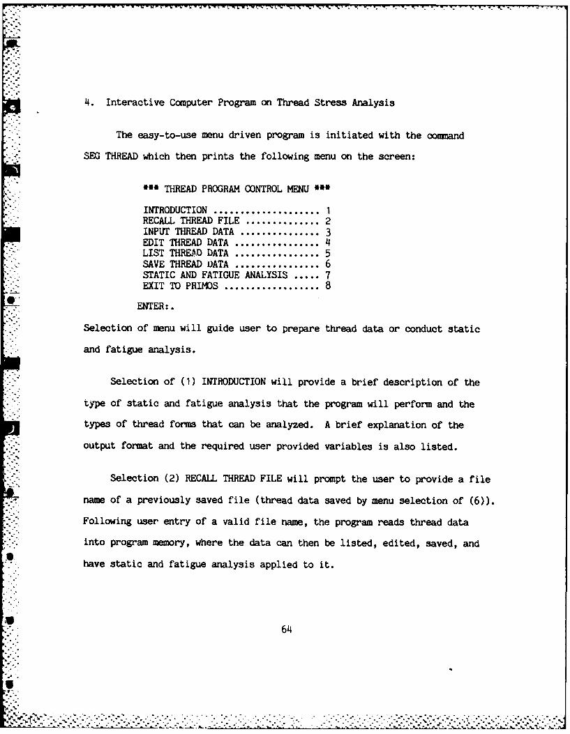
4. Interactive Computer Program on Thread Stress Analysis
The easy-to-use menu driven program is initiated with the command
SEG THREAD which then prints the following menu on the screen:
*** THREAD PROGRAM CONTROL MENU *
INTRODUCTION .................... 1RECALL THREAD FILE ............. 2INPUT THREAD DATA .............. 3EDIT THREAD DATA ................ 4LIST THREAD DATA ................ 5SAVE THREAD DATA ................ 6STATIC AND FATIGUE ANALYSIS ..... 7EXIT TO PRIMOS .. . .. ....... 8
ENTER:.
Selection of menu will guide user to prepare thread data or conduct static
and fatigue analysis.
Selection of (1) INTRODUCTION will provide a brief description of the
type of static and fatigue analysis that the program will perform and the
types of thread forms that can be analyzed. A brief explanation of the
output format and the required user provided variables is also listed.
Selection (2) RECALL THREAD FILE will prompt the user to provide a file
name of a previously saved file (thread data saved by menu selection of (6)).
Following user entry of a valid file name, the program reads thread data
into program memory, where the data can then be listed, edited, saved, and
have static and fatigue analysis applied to it.
64
Uo
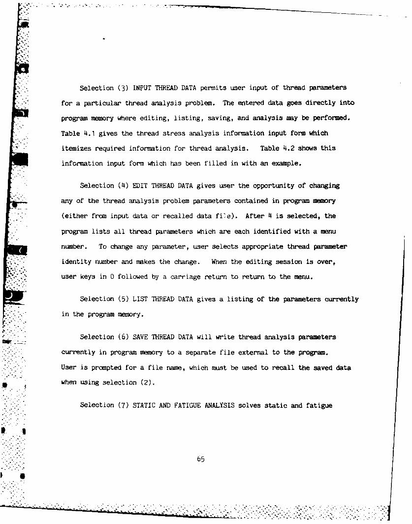
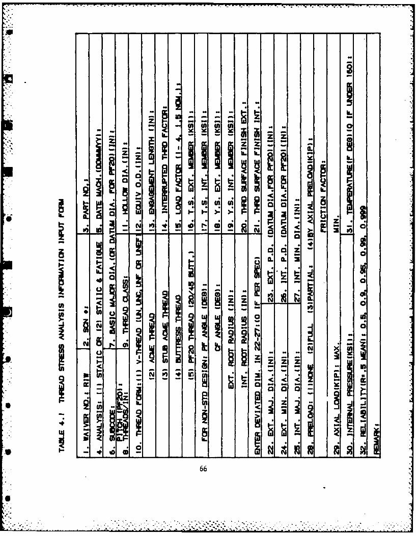
Selection (3) INPUT THREAD DATA permits user input of thread parameters
for a particular thread analysis problem. The entered data goes directly into
program memory where editing, listing, saving, and analysis may be performed.
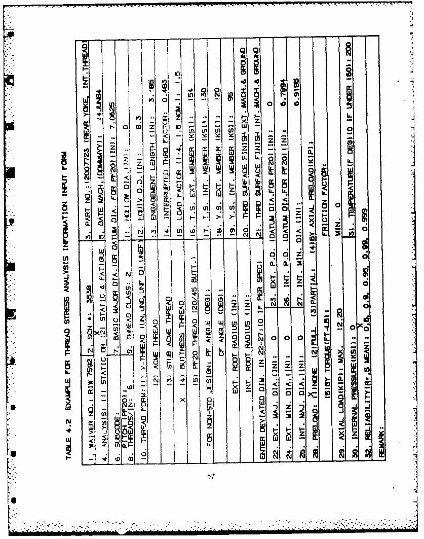
Table 4.1 gives the thread stress analysis information input form which
itemizes required information for thread analysis. Table 4.2 shows this
information input form which has been filled in with an example.
Selection (4) EDIT THREAD DATA gives user the opportunity of changing
any of the thread analysis problem parameters contained in program memory
*i •I (either from input data or recalled data fie). After 4 is selected, the
program lists all thread parameters which are each identified with a menu
number. To change any parameter, user selects appropriate thread parameter
identity number and makes the change. When the editing session is over,
user keys in 0 followed by a carriage return to return to the menu.
Selection (5) LIST THREAD DATA gives a listing of the parameters currently
in the program memory.
_ -- Selection (6) SAVE THREAD DATA will write thread analysis parameters
currently in program memory to a separate file external to the program.
User is prompted for a file name, which must be used to recall the saved data
- when using selection (2).
Selection (7) STATIC AND FATIGUE ANALYSIS solves static and fatigue
65o-°......., .
,- . . .
44 i I -
ILi
r:~ op
a6
'III
iLn 40*n6* =*(
22
It CL(Dj
IL -
< wp ci
w; J 1T. .~z . ..
['.-
< 5U)..
I. . -
,- - I.
I . I , i' - IN
Z SIb, C)
- - i
67
(simple load history) problems under assumption of elasticity for thread
parameters currently in program memory. In static analysis, load capacity
of the threaded joint and safety factors are calculated under maximum, minimum
and actual material conditions corresponding to yield stress and tensile
strength. In fatigue analysis, safety factors corresponding to various
fatigue life cycle ranges are estimated based on user supplied parameters.
Selection (8) EXIT TO PRIMOS returns user to the PRIME operating system
at the conclusion of the thread analysis session.
Specific example sessions for V, Acme, Stub Acme, Buttress, and PF20
Watervliet Special Threads are given in appendices A.5 through A.9, respectively.
The interactive thread analysis program documented in this report is
written in PRIME F77, an extended version of FORTRAN 77 which conforms fully
to ANSIx3.9-1978. A complete software reference including program variable
list, common block definitions, source code listing, and compile load instructions
is provided in appendices A.I through A.4.
68
5. Dijcussion
The object of this report is to establish a program for estimating load
capacities and fatigue life cycles of designed threaded connection subjected
to a simple cyclic loading. Elastic material property is assumed in this
report. For a more realistic material model and numerical method of analysis,
finite element analysis with assumption of elastic-plastic material model is
recommended for tnis project in the future. This approach nas been explored
oy many researches such as O'Hara (22), and Chen and O'Hara (23).
A parabolic load distribution on pressure flank is proposed in this report
to reflect stress response in the threaded connection. Flank angle deviation
is assumed to be negligible in the program. If flank angle deviation is
significant for a non-conforming thread, bias load distribution may occur and
a complicated load distribution program will be needed to describe the mismatched
flank angles of non-conforming threaded connection. Hoop stress of internal
thread member is considered far less than fillet stresses due to bending and
axial loading and is not included in the program. However for external thread
member, hoop stress is calculated if internal pressure applied. It is noticed
that stress due to shear is far less than triaxial root stresses so that thread
failure usually due to fillet stress. Shear failure takes place when threads
have significant truication and reduce thread contact surface.
In fatigue analysis, load history is calculated by using user supplied
69
. . .. . . . . . . . .'
.--' -'i.' <'-ii . .- i '-. i~ -.i-..ili " i~ - -< ." .''. i -<.-i .' -. - -i --..--- 'i . '<- -ii--' '-i.- . . i -'l- l I i i~ . i 2--i il'i ':" -i.-. -.
axial maximum applied and minimum applied load to calculated alternating and
mean stresses. Internal pressure applied to threaded joint is assumed to be
in phase with load history. The threaded connection is assumed to be subjected
to axial loading, hence, size effect is Cd=1 and load type effect is Cl=0.9. In
the program, an experimental fatigue strength diagram for alloy steel with tensile
strength Su=125 to 180 ksi under axial loading is adopted. To estimate safety
factors at various fatigue life cycles, factors of size effect (Cd), surface
finish effect (Cs), load type effect (Cl), modifying factor due to fatigue
stress concentration (Ck), temperature effect (Ct) and reliability factor (Cr)
are applied. Those factors are adopted from various sources, although precision
is not claimed, but the results can serve as a reference or indicator. For
material with tensile strength Su less than 125 ksi or larger than 180 ksi, S-N
curves with equation (3.9.10) and Goodman lines with equation (3.9.22) can be
applied to find fatigue life cycle and safety factor at various fatigue life
cycles.
Currently, this program only cover thread forms of UN, UNC, UNF, UNEF, AC E,
Stub A(CIE, Buttress and PF20 Watervliet special thread. It is planned to add
additional thread forms used on the components manufactured at Rock Island Arsenal.
70i
4- . . - =
6. References
1. FED-STD-H28, Screw-thread standards for federal services,
General service Administration, 1978.
2. ANSI B1, American National Standard, ASME, 1973.
3. Smith C.W.,"Effect of fit and truncation on the strength
of Whitworth threads",Engineer,July 22,1949.
4. Field J.E., Engineer, #200 and #301, 1955.
5. Sopwith D.G.,"The distribution of load in screw threads" Proceeding
Institute of Mechanical Engineering, pp.373-383, 1948.
6. Goodier J.N.,"The distribution of load in the threads of screws"
Trans. A.S.M.E.,vol.62, pp.A-10, 1940.
7. Hetenyi M. ,"A photoelastic study of bolt and nut fastenings"
Trans. A.S.M.E.,vol.65, pp.A-93, 1943.
8. Chalupnik J.D. ,"Stress concentrations in bolt-thread roots"
Experimental Mechanics, 1967.
9. Cazaud R.,"Fatigue of metals", Chapman and Hall,London,1953.
10. Marino R.l. and Riley W.F.,"Optimizing thread-root countours
using photoelastic methods",Experimental Mechanics,Jan. 1964. |
11. Weigle R.E. and Lasselle R.R.,"Experimental techniques for
predicting fatigue failure of cannon-breech mechanisms"
February 1965.
12. Neuber H. and Springer J.,Kerbspannungslehre,Berlin 1937 & 1958,
trans. by Navy Dept.,David Taylor Model Basin,Washington,Nov.1945.
71
-°
..................................................................................
13. Heywood R.B.,"Designing against fatigue of metals", Reinhold
Publishing Corp., New York 1962.
14. Juvinall R.C.,"Stress strain and strength",McGraw-Hill Inc.,1967.
15. Shigley J.E.,"Mechanr al engineering design",McGraw-Hill Inc.,1977.
16. Blake J.C. and Kurtz H.J.,"The uncertainties of measuring fastener
preload",Machine Design,vol.37, pp.128-131, Sept. 30, 1965.
17. Lewis W.,Proc. Eng. Club, Philadelphia,vol.10, p.16, 1893.
18. Heywood R.B.,"Tensile fillet stresses in loaded projections"
Proc. IME, pp.384-391, 1948.
19. Kelley B.W. and Pedersen R.,"The beam strength of modern gear
tooth-design",Trans. SAE, vol.66, pp.137-157, 1958.
20. O'Hara G.P.,"Stress concentration in screw threads", ARRADCOM
Technical Report, ARLCB-TR-80010, 1980.
21. Peterson R.E.,"Fatigue of metals in engineering and design"
ASTM, Philadelphia, 1962.
22. O'hara G.P.,"Elastic-plastic analysis of screw threads", AMMS
Technical Report, ARLCB-TR-80043, November 1980
23. Chen P.C.T. and O'Hara G.P.,"Finite element results of pressurized thick
tubes based on two elastic-plastic material models", AMCMS
Technical Report, ARLCB-TR-83047, December 1983
72
APPENDICES
I Al
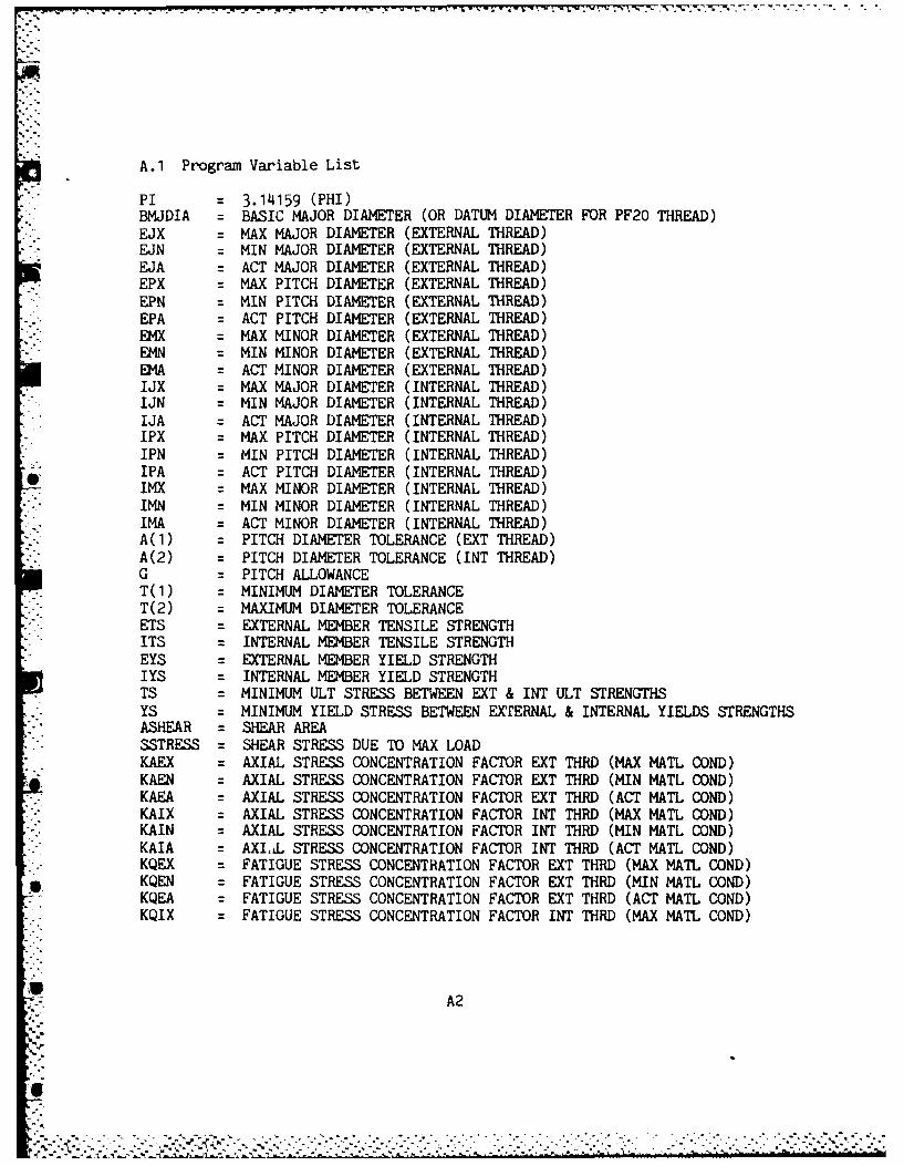
A.1 Program Variable List
PI = 3.14159 (PHI)BMJDIA = BASIC MAJOR DIAMETER (OR DATUM DIAMETER FOR PF20 THREAD)EJX = MAX MAJOR DIAMETER (EXTERNAL THREAD)EJN = MIN MAJOR DIAMETER (EXTERNAL THREAD)EJA = ACT MAJOR DIAMETER (EXTERNAL THREAD)EPX = MAX PITCH DIAMETER (EXTERNAL THREAD)EPN = MIN PITCH DIAMETER (EXTERNAL THREAD)EPA = ACT PITCH DIAMETER (EXTERNAL THREAD)EMX = MAX MINOR DIAMETER (EXTERNAL THREAD)EMN = MIN MINOR DIAMETER (EXTERNAL THREAD)EMA = ACT MINOR DIAMETER (EXTERNAL THREAD)IJX = MAX MAJOR DIAMETER (INTERNAL THREAD)IJN = MIN MAJOR DIAMETER (INTERNAL THREAD)IJA = ACT MAJOR DIAMETER (INTERNAL THREAD)IPX = MAX PITCH DIAMETER (INTERNAL THREAD)IPN = MIN PITCH DIAMETER (INTERNAL THREAD)IPA = ACT PITCH DIAMETER (INTERNAL THREAD)IMX = MAX MINOR DIAMETER (INTERNAL THREAD)IMN = MIN MINOR DIAMETER (INTERNAL THREAD)IMA = ACT MINOR DIAMETER (INTERNAL THREAD)A(1) = PITCH DIAMETER TOLERANCE (EXT THREAD)A(2) = PITCH DIAMETER TOLERANCE (INT THREAD)G = PITCH ALLOWANCET(1) = MINIMUM DIAMETER TOLERANCE
- T(2) = MAXIMUM DIAMETER TOLERANCEETS = EXTERNAL MEMBER TENSILE STRENGTHITS = INTERNAL MEMBER TENSILE STRENGTHEYS = EXTERNAL MEMBER YIELD STRENGTHIYS = INTERNAL MEMBER YIELD STRENGTHTS = MINIMUM ULT STRESS BETWEEN EXT & INT ULT STRENGTHSYS = MINIMUM YIELD STRESS BETWEEN EXTERNAL & INTERNAL YIELDS STRENGTHSASHEAR = SHEAR AREASSTRESS = SHEAR STRESS DUE TO MAX LOADKAEX = AXIAL STRESS CONCENTRATION FACTOR EXT THRD (MAX MATL COND)KAEN = AXIAL STRESS CONCENTRATION FACTOR EXT THRD (MIN MATL COND)KAEA = AXIAL STRESS CONCENTRATION FACTOR EXT THRD (ACT MATL COND)KAIX = AXIAL STRESS CONCENTRATION FACTOR INT THRD (MAX MATL COND)KAIN : AXIAL STRESS CONCENTRATION FACTOR INT THRD (MIN MATL COND)KAIA = AXI.LL STRESS CONCENTRATION FACTOR INT THRD (ACT MATL COND)KQEX = FATIGUE STRESS CONCENTRATION FACTOR EXT THRD (MAX MATL COND)KQEN = FATIGUE STRESS CONCENTRATION FACTOR EXT THRD (MIN MATL COND)KQEA = FATIGUE STRESS CONCENTRATION FACTOR EXT THRD (ACT MATL COND)
" KQIX : FATIGUE STRESS CONCENTRATION FACTOR INT THRD (MAX MATL COND)
A2
°
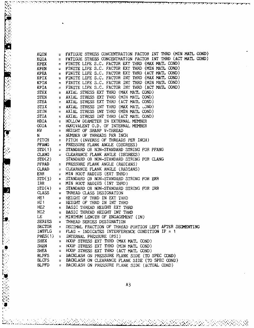
|. ', V. . - . . s ' r ' '
KQIN FATIGUE STRESS CONCENTRATION FACTOR INT THRD (MIN MATL COND)KQIA : FATIGUE STRESS CONCENTRATION FACTOR INT THRD (ACT MATL COND)KPEX : FINITE LIFE S.C. FACTOR EXT THRD (MAX MATL COND)KPEN = FINITE LIFE S.C. FACTOR EXT THRD (MIN MATL COND)KPEA = FINITE LIFE S.C. FACTOR EXT THRD (ACT MATh COND)KPIX = FINITE LIFE S.C. FACTOR INT THRD (MAX MATL COND)KPIN = FINITE LIFE S.C. FACTOR INT THRD (MIN MATL COND)KPIA = FINITE LIFE S.C. FACTOR INT THRD (ACT MATL COND)
-- STEX = AXIAL STRESS EXT THRD (MAX MAT L COND)STEN = AXIAL STRESS EXT THRD (MIN MATL CONDSTEA = AXIAL STRESS EXT THRD (ACT MATL COND)STIX = AXIAL STRESS ENT THRD (MAX MATL COND)STIN = AXIAL STRESS ENT THRD (MIN MATL COND)STIA = AXIAL STRESS INT THRD (ACT MATL COND)HDIA = HOLLOW DIAMETER IN EXTERNAL MEMBERODIA = EQUIVALENT O.D. OF INTERNAL MEMBERHV = HEIGHT OF SHARP V-THREAD
. N = NUMBER OF THREADS PER INCHPITCH = PITCH (INVERSE OF THREADS PER INCH)PFANG = PRESSURE FLANK ANGLE (DEGREES)
,y STD(l) = STANDARD OR NON-STANDARD STRING FOR PFANGCLANG = CLEARANCE FLANK ANGLE (DEGREES)
i STD(2) STANDARD OR NON-STANDARD STRING FOR CLANGPFRAD = PRESSURE FLANK ANGLE (RADIANS)CLRAD = CLEARANCE FLANK ANGLE (RADIANS)ERR = MIN ROOT RADIUS (EXT THRD)STD(3) = STANDARD OR NON-STANDARD STRING FOR ERRIRR = MIN ROOT RADIUS (INT THRD)STD(4) = STANDARD OR NON-STANDARD STRING FOR IRRCLASS = THREAD CLASS DESIGNATIONHEI = HEIGHT OF THRD IN EXT THRDHII = HEIGHT OF THRD IN INT THRDHE2 = BASIC THREAD HEIGHT EXT THRDH12 = BASIC THREAD HEIGHT INT THRDLE = MINIMUM LENGTH OF ENGAGEMENT (IN)SERIES = THREAD SERIES DESIGNATIONSECTOR = DECIMAL FRACTION OF THREAD PORTION LEFT AFTER SEGMENTINGINTFLG = FLAG - INDICATES INTERFERENCE CONDITION IF = 1PRES(1) = INTERNAL PRESSURE (PSI)SHEX = HOOP STRESS EXT THRD (MAX MATL COND)SHEN = HOOP STRESS EXT THRD (MIN MATL COND)SHEA = HOOP STRESS EXT THRD (ACT MATL COND)BLPFS = BACKLASH ON PRESSURE FLANK SIDE (TO SPEC COND)BLCFS = BACKLASH ON CLEARANCE FLANK SIDE (TO SPEC COND)BLPFD = BACKLASH ON PRESSURE FLANK SIDE (ACTUAL COND)
A3
a
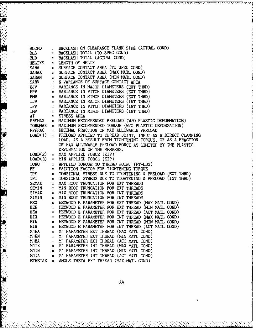
BLCFD : BACKLASH ON CLEARANCE FLANK SIDE (ACTUAL COND)BLS : BACKLASH TOTAL (TO SPEC COND)BLD : BACKLASH TOTAL (ACTUAL COND)HELIXS = LENGTH OF HELIXSARA = SURFACE CONTACT AREA (TO SPEC COND)SARAX = SURFACE CONTACT AREA (MAX MATL COND)SARAN = SURFACE CONTACT AREA (MIN MATL COND)SARV = % VARIANCE OF SURFACE CONTACT AREAEJV = VARIANCE IN MAJOR DIAMETERS (EXT THRD)EPV = VARIANCE IN PITCH DIAMETERS (EXT THRD)EMV = VARIANCE IN MINOR DIAMETERS (EXT THRD)IJV = VARIANCE IN MAJOR DIAMETERS (INT THRD)IPV VARIANCE IN PITCH DIAMETERS (INT THRD)IMV = VARIANCE IN MINOR DIAMETERS (INT THRD)AT = STRESS AREAPREMAX = MAXIMUM RECOMMENDED PRELOAD (W/O PLASTIC DEFORMATION)TORQMAX = MAXIMUM RECOMMENDED TORQUE (W/O PLASTIC DEFORMATION)FPFRAC = DECIMAL FRACTION OF MAX ALLOWABLE PRELOADLOAD(I) = PRELOAD APPLIED TO THREAD JOINT, INPUT AS A DIRECT CLAMPING
LOAD, AS A RESULT FROM TIGHTENING TORQUE, OR AS A FRACTIONOF MAX ALLOWABLE PRELOAD FORCE AS LIMITED BY THE PLASTICDEFORMATION OF THE MEMBERS.
LOAD(2) = MAX APPLIED FORCE (KIP)LOAD(3) = MIN APPLIED FORCE (KIP)TORQ = APPLIED TORQUE TO THREAD JOINT (FT-LBS)FF = FRICTION FACTOR FOR TIGHTENING TORQUETPE = TORSIONAL STRESS DUE TO TIGHTENING & PRELOAD (EXT THRD)TPI = TORSIONAL STRESS DUE TO TIGHTENING & PRELOAD (INT THRD)SEMAX = MAX ROOT TRUNCATION FOR EXT THREADSSEMIN = MIN ROOT TRUNCATION FOR EXT THREADSSIMAX = MAX ROOT TRUNCATION FOR INT THREADSSIMIN = MIN ROOT TRUNCATION FOR INT THREADSEEX = HEYWOOD E PARAMETER FOR EXT THREAD (MAX MATL COND)EEN = HEYWOOD E PARAMETER FOR EXT THREAD (MIN MATL COND)EEA = HEYWOOD E PARAMETER FOR EXT THREAD (ACT MATL COND)EIX = HEYWOOD E PARAMETER FOR INT THREAD (MAX MATL COND)EIN = HEYWOOD E PARAMETER FOR INT THREAD (MIN MATL COND)EIA = HEYWOOD E PARAMETER FOR INT THREAD (ACT MATL COND)MIEX = Ml PARAMETER EXT THREAD (MAX MATL COND)MIEN = Ml PARAMETER EXT THREAD (MIN MATL COND)MIEA = Ml PARAMETER EXT THREAD (ACT MATL COND)MIIX = Ml PARAMETER INT THREAD (MAX MATL COND)MlIN = MI PARAMETER INT THREAD (MIN MATL COND)MiIA = Ml PARAMETER INT THREAD (ACT MATL COND)ETHETAX = ANGLE THETA EXT THREAD (MAX MATL COND)
A4
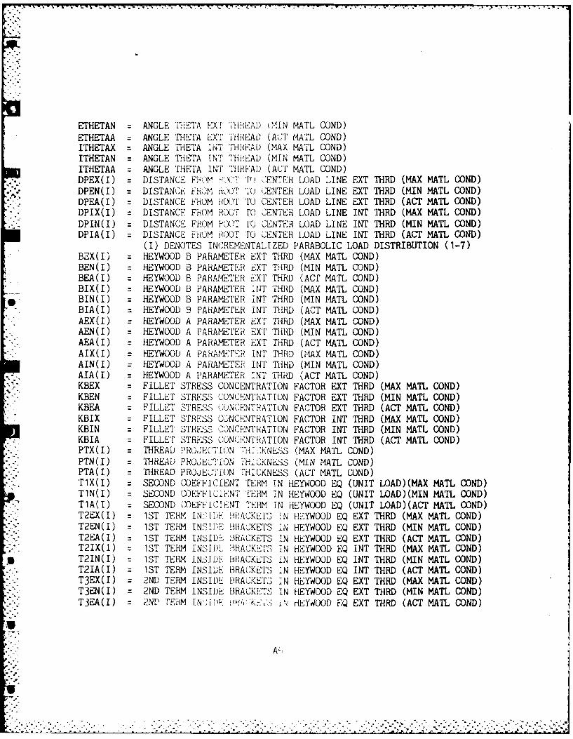
ETHETAN = ANGLE 'lliETA EXI THREAD kMIN MATL COND)ETHETAA = ANGLE THETA EXT THREAD (ACT MATL COND)ITHETAX = ANGLE THETA INT THREAD (MAX MATL COND)ITHETAN = ANGLE THETA lINT THREiAD (MIN MATL COND)ITHETAA = ANGLE THETA INT THEFAD (ACT MATL COND)DPEX(I) =DISTANCE ERJiM V >XITTO NTER LOAD LINE EXT THRD (MAX MATL COND)DPEN(I) = DISTANC,'E FRO,-M n'iT' TO -ENTER LOAD LINE EXT THRD (MIN MATL COND)DPEA(I = DISTANCE FROM hO(-l To CENTER LOAD LINE EXT THRD (ACT MATL GOND)DPIX(I) = DISTANCE FHOM ROO)T L'O CENTER LOAD LINE TNT THRD (MAX MATL COND)DPIN(I) = DISTANCE FROM P' )T 10 CENTER LOAD LINE INT THRD (MIN MATh COND)DPIA(I = DISTANCE FRO lM ROOT TO "CENTER LOAD LINE INT THRD (ACT MATh COND)
(I) DENOTES INCREMENTALIZED PARABOLIC LOAD DISTRIBUTION (1-7)BEX(I) = HEYWOOD B PARAMETER EXT THRD (MAX MATL COND)BEN(I) =HEYWOOD B PARAMETER EXT THED (MIN MATL COND)BEA(I) = H-EYWOOD B PARAMETER EXT THED (Acr MATL COND)BIX(I) =HEYWOOD B PARAMETlER ItNT I'HRD (MAX MATL COND)
*BIN(I) = HEYWOOD B PARAMETER IN'T THRD (MIN MATL COND)BIA(I) =HEYWOOD B PARAMETER INT THRD (ACT MATL COND)AEX(I) =HEYWOOD A PARAMETER EXT THRD (MAX MATh COND)
*AEN(I = HEYWOOD A PARAMETER EXT THRD (MIN MATL COND)AEA(I) = HEYWOOD A PARAMETER EXT THED (ACT MATh COND)AIX(I) = HEYWOOD A PARAMETERP iN'r THRD (MAX MATh COND)AIN(I) = HEYWOOD A PARAMETER INT THRD (MIN MATL COND)AIA(I = HEYWOOD A PARAMETER TNT THRD (ACT MATL COND)KBEX = FILLET STRESS CONCENTRATION FACTOR EXT THRD (MAX MATL COND)KBEN =FILLET STRESS CONCENTRATION FACTOR EXT THRD (MIN MATL COND)KBEA =FILLET STRESS WNCE"NTRATION FACTOR EXT THRD (ACT MATL COND)KBIX =FILLET STRESS 'CONCENTRATION FACTOR INT THRD (MAX MATh COND)KBIN = FILLET STRESS COINCENTRATION FACTOR INT THRD (MIN MATL COND)KBIA =FILLET STRES-'S Cl:NC!.NTRAT ION FACTOR INT THRD (ACT MATh COND)PTX(I) = THREAD P'ROJECIO 7i"'(KNESS (MAX MATL GOND)PTN(I) = THREAD PROJECTIO1N !'HiCKNLSS (MIN MATL COND)PTA(I) = THREAD PROJE'1'iON THICKNESS (ACT MATL COND)TlX(I) =SECOND COEFFICIENT TERM IN HEYWOOD EQ (UNIT LAD)(MAX MATL COND)TlN(I) = SECOND COEFFICIENT TERM IN HEYWOOD EQ (UNIT LOAD)(MIN MATL COND)TWO =) SECOND LnEFFICIENT TERM IN HEYWOOD EQ (UNIT LOAD)(ACT MATL COND)T2EX(I) = 1ST TERM I1 1D 10r'BACKEIFS f N HE YWOOD EQ EXT THRD (MAX MATh COND)T2EN(I) = 1ST TrERM IN BD RACKETS IN HEYWOOD EQ EXT THRD (MIN MATh COND)T2EA(I) = 1ST TERM INSIDR- BRACKETS 11N HEYWOOD EQ EXT THRD (ACT MATL GOND)
T2IX(I)~ 1ST TR NDL !RCESI HYODE INT THRD (MA MATh COND)*T21N(I) = 1ST TERM I N SID', 1RACKET I N HEYWOOD EQ NTTD(MMATLCD
T21N(I) = 1ST TERM INSI DE BRACKETS IN HEYWOOD EQ INT THRD (ACT MATh COND)
T3EX(I) = 2ND TERM INSIDE BRACKETS IN HEYWOOD EQ EXT THRD (MAX MATL COND)T3EN(I) = 2ND TERM INSIDE BRACKETS IN HEYWOOD EQ EXT THRD (MIN MATh COND)T3EA(I) =2ND TFEMI TNiiD 11; X t- ii HEY400D EQ EXT THRD (ACT MATL COND)
akor "
,". A"
:....................................-..i.. . . . .
. . .. . . . . . . . . . . . . . . . . . . . . . . .-. . . . . . . . . . ..G. . .ETHETAN....NGLE.............................TL....D
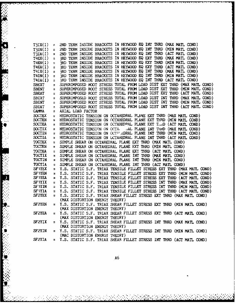
.... i
T31X(I) = 2ND TERM INSIDE BRACKETS IN HEYWOOD EQ INT THRD (MAX MATL COND)T3IN(I) = 2ND TERM INSIDE BRACKETS IN HEYWOOD EQ INT THRD (MIN MATL COND)T31A(I) = 2ND TERM INSIDE BRACKETS IN HEYWOOD EQ INT THRD (ACT MATL COND)T4EX(I) = 3RD TERM INSIDE BRACKETS IN HEYWOOD EQ EXT THRD (MAX MATL COND)T4EN(I) = 3RD TERM INSIDE BRACKETS IN HEYWOOD EQ EXT THRD (MIN MATL COND)T4EA(I) = 3RD TERM INSIDE BRACKETS IN HEYWOOD EQ EXT THRD (ACT MATL COND)T41X(I) = 3RD TERM INSIDE BRACKETS IN HEYWOOD EQ INT THRD (MAX MATL COND)T4IN(I) = 3RD TERM INSIDE BRACKETS IN HEYWOOD EQ INT THRD (MIN MATL COND)T4IA(I) = 3RD TERM INSIDE BRACKETS IN HEYWOOD EQ INT THRD (ACT MATL COND)SBEXT = SUPERIMPOSED ROOT STRESS TOTAL FROM LOAD DIST EXT THRD (MAX MATL COND)SBENT = SUPERIMPOSED ROOT STRESS TOTAL FROM LOAD DIST EXT THRD (MIN MATL COND)SBEAT = SUPERIMPOSED ROOT STRESS TOTAL FROM LOAD DIST EXT THRD (ACT MATL COND)SBIXT = SUPERIMPOSED ROOT STRESS TOTAL FROM LOAD DIST INT THRD (MAX MATL COND)SBINT = SUPERIMPOSED ROOT STRESS TOTAL FROM LOAD DIST INT THRD (MIN MATL COND)SBIAT = SUPERIMPOSED ROOT STRESS TOTAL FROM LOAD DIST INT THRD (ACT MATL COND)GAMMA = AXIAL LOAD FACTORSOCTEX = HYDROSTATIC TENSION ON OCTAHEDRAL PLANE EXT THRD (MAX MATL COND)SOCTEN = HYDROSTATIC TENSION ON OCTAHEDRAL PLANE EXT THRD (MIN MATL COND)
. SOCTEA = HYDROSTATIC TENSION ON OCTAHEDRAL PLANE EXT Ti..D (ACT MATL COND)SOCTIX = HYDROSTATIC TENSION ON OCTA. tAL PLANE ENT THAID (MAX MATL COND)SOCTIN = HYDROSTATIC TENSION ON OCTP'.rDRAL PLANE INT THRD (MIN MATL COND)SOCTIA = HYDROSTATIC TENSION ON OCTAHEDRAL PLANE INT THRD (ACT MATL COND)TOCTEX = SIMPLE SHEAR ON OCTAHEDRAL PLANE EXT THRD (MAX MATL COND)TOCTEN = SIMPLE SHEAR ON OCTAHEDRAL PLANE EXT THRD (MIN MATL COND)TOCTEA = SIMPLE SHEAR ON OCTAHEDRAL PLANE EXT THRD (ACT MATL COND)TOCTIX = SIMPLE SHEAR ON OCTAHEDRAL PLANE INT THRD (MAX MATL COND)TOCTIN = SIMPLE SHEAR ON OCTAHEDRAL PLANE INT THRD (MIN MATL COND)TOCTIA = SIMPLE SHEAR ON OCTAHEDRAL PLANE INT THRD (ACT MATL COND)SF.YEX = Y.S. STATIC S.F. TRIAX TENSILE FILLET STRESS EXT THRD (MAX MATL COND)SFlYEN = Y.S. STATIC S.F. TRIAX TENSILE FILLET STRESS EXT THRD (MIN MATL COND)SFIYEA = Y.S. STATIC S.F. TRIAX TENSILE FILLET STRESS EXT THRD (ACT MATL COND)SFlYIX = Y.S. STATIC S.F. TRIAX TENSILE FILLET STRESS INT THRD (MAX MATL COND)SFlYIN = Y.S. STATIC S.F. TRIAX TENSILE FILLET STRESS INT THRD (MIN MATL COND)SFlYIA = Y.S. STATIC S.F. TRIAX TENSILE FILLET STRESS INT THRD (ACT MATL COND)SF2YEX = Y.S. STATIC S.F. TRIAX SHEAR FILLET STRESS EXT THRD (MAX MATL COND)
(MAX DISTORTION ENERGY THEORY)SF2YEN = Y.S. STATIC S.F. TRIAX SHEAR FILLET STRESS EXT THRD (MIN MATL COND)
(MAX DISTORTION ENERGY THEORY)SF2YEA : Y.S. STATIC S.F. TRIAX SHEAR FILLET STRESS EXT THRD (ACT MATL COND)
(MAX DISTORTION ENERGY THEORY)SF2YIX : Y.S. STATIC S.F. TRIAX SHEAR FILLET STRESS INT THRD (MAX MATh COND)
(MAX DISTORTION ENERGY THEORY)SF2YIN = Y.S. STATIC S.F. TRIAX SHEAR FILLET STRESS INT THRD (MIN MATL COND)
(MAC DISTORTION ENERGY THEORY)• " SF2YIA : Y.S. STATIC S.F. TRIAX SHEAR FILLET STRESS INT THRD (ACT MATL COND)
U A6
. ..

(MAX DISTORTION ENERGY THEORY)SFITEX = T.S. STATIC S.F. TRIAX TENSILE FILLET STRESS EXT THRD (MAX MATL COND)SFlTEN = T.S. STATIC S.F. TRIAX TENSILE FILLET STRESS EXT THRD (MIN MATL COND)SFlTEA = T.S. STATIC S.F. TRIAX TENSILE FILLET STRESS EXT THRD (ACT MATL COND)SFITIX = T.S. STATIC S.F. TRIAX TENSILE FILLET STRESS INT THRD (MAX MATL COND)SFITIN = T.S. STATIC S.F. TRIAX TENSILE FILLET STRESS INT THRD (MIN MATL COND)SFlTIA = T.S. STATIC S.F. TRIAX TENSILE FILLET STRESS INT THRD (ACT MATL COND)SF2TEX = T.S. STATIC S.F. TRIAX SHEAR FILLET STRESS EXT THRD (MAX MATL COND)
(MAX DISTORTION ENERGY THEORY)SF2TEN = T.S. STATIC S.F. TRIAX SHEAR FILLET STRESS EXT THRD (MIN MATL COND)
(MAX DISTORTION ENERGY THEORY)SF2TEA = T.S. STATIC S.F. TRIAX SHEAR FILLET STRESS EXT THRD (ACT MATL COND)
(MAX DISTORTION ENERGY THEORY)SF2TIX = T.S. STATIC S.F. TRIAX SHEAR FILLET STRESS INT THRD (MAX MATL COND)
(MAX DISTORTION ENERGY THEORY)SF2TIN = T.S. STATIC S.F. TRIAX SHEAR FILLET STRESS INT THRD (MIN MATL COND)
(MAX DISTORTION ENERGY THEORY)SF2TIA T.S. STATIC S.F. TRIAX SHEAR FILLET STRESS INT THRD (ACT MATL COND)
(MAX DISTORTION ENERGY THEORY)SFYEX = OVERALL STATIC S.F. EXT THRD (MAX MATL COND) BASED ON YSSFYEN = OVERALL STATIC '.F. EXT THRD (MIN MATL COND) BASED ON YSSFYEA = OVERALL STATIC S F. EXT THRD (ACT MATL COND) BASED ON YSSFYIX = OVERALL STATIC S.L'. INT THRD (MAX MATL COND) BASED ON YSSFYIN = OVERALL STATIC S.F. INT THRD (MIN MATL COND) BASED ON YSSFYIA = OVERALL STATIC S.F. INT THRD (ACT MATL COND) BASED ON YSSFTEX = OVERALL STATIC S.F. EXT THRD (MAX MATL COND) BASED ON TSSFTEN OVERALL STATIC S.F. EXT THRD (MIN MATL COND) BASED ON TSSFTEA = OVERALL STATIC S.F. EXT THRD (ACT MATL COND) BASED ON TSSFTIX = OVERALL STATIC S.F. INT ThRD (MAX MATL COND) BASED ON TSSFTIN = OVERALL STATIC S.F. INT THRD (MIN MATL COND) BASED ON TSSFTIA = OVERALL STATIC S.F. INT THRD (ACT MATL COND) BASED ON TSCL = WOAD CONSTANTCD = SIZE EFFECTFCYCLE = WADING CONDITION FOR FATIGUE EVALUATIONECF SURFACE FINISH FACTOR (EXT THRD)ICF = SURFACE FINISH FACTOR (INT THRD)FE;UHF = SURFACE FINISH TEXTURE (EXf TiHUiD)
=-JR"S 'SURFACE FINISH TEXT STRING (EXT THRD)L;URF = SURFACE FINISH TExrulE (INT THRD)IIF:; = SURFACE FINISH TEXT STRING (INT THRl). TEMPERATURE (DE(;R EE.] F)
(=T TE ERATURE EFFECT FACTORHEI. RELIABILITY OF STANDARD MATERIAL PROPERTIESCR RELIABILITY FACTOREKF FATIGUE STRESS CONCENTRATION FACTOR (EXTERNAL THRD)
A7
. .'
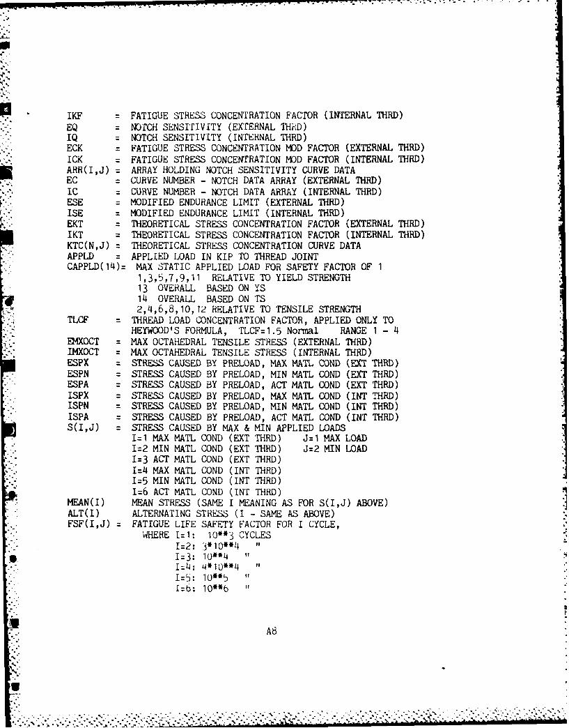
* U -J J _ . | I - - p. - . -.1 , . , -. . . . -. . . . .' . - • • - . -" . . .
.S
IKF = FATIGUE STRESS CONCENTRATION FACTOR (INTERNAL THRD)EQ = NOTCH SENSITIVITY (EXTERNAL THRD)IQ = NOTCH SENSITIVITY (INTERNAL THRD)ECK = FATIGUE STRESS CONCENTRATION MOD FACTOR (EXTERNAL THRD)ICK = FATIGUE STRESS CONCENTRATION MOD FACTOR (INTERNAL THRD)ARR(I,J) = ARRAY HOLDING NOTCH SENSITIVITY CURVE DATAEC = CURVE NUMBER - NOTCH DATA ARRAY (EXTERNAL THRD)IC = CURVE NUMBER - NOTCH DATA ARRAY (INTERNAL THRD)ESE = MODIFIED ENDURANCE LIMIT (EXTERNAL THRD)ISE = MODIFIED ENDURANCE LIMIT (INTERNAL THRD)EKT = THEORETICAL STRESS CONCENTRATION FACTOR (EXTERNAL THRD)IKT = THEORETICAL STRESS CONCENTRATION FACTOR (INTERNAL THRD)
KTC(N,J) = THEORETICAL STRESS CONCENTRATION CURVE DATAAPPLD = APPLIED LOAD IN KIP TO THREAD JOINTCAPPLD(14)= MAX STATIC APPLIED LOAD FOR SAFETY FACTOR OF 1
1,3,5,7,9,11 RELATIVE TO YIELD STRENGTH13 OVERALL BASED ON YS14 OVERALL BASED ON TS2,4,6,8,10,12 RELATIVE TO TENSILE STRENGTH
TLCF = THREAD LOAD CONCENTRATION FACTOR, APPLIED ONLY TOHEYWOOD'S FORMULA, TLCF=1.5 Normal RANGE 1 - 4
EMXOCT = MAX OCTAHEDRAL TENSILE STRESS (EXTERNAL THRD)IMXOCT = MAX OCTAHEDRAL TENSILE STRESS (INTERNAL THRD)ESPX : STRESS CAUSED BY PRELOAD, MAX MATL COND (EXT THRD)ESPN = STRESS CAUSED BY PRELOAD, MIN MATL COND (EXT THRD)ESPA = STRESS CAUSED BY PRELOAD, ACT MATL COND (EXT THRD)ISPX = STRESS CAUSED BY PRELOAD, MAX MATL COND (INT THRD)ISPN = STRESS CAUSED BY PRELOAD, MIN MATL COND (INT THRD)ISPA = STRESS CAUSED BY PRELOAD, ACT MATL COND (INT THRD)S(I,J) = STRESS CAUSED BY MAX & MIN APPLIED LOADS
I=1 MAX MATL COND (EXT THRD) J=1 MAX LOADI=2 MIN MATL COND (EXT THRD) J=2 MIN LOADI=3 ACT MATL COND (EXT THRD)1I=4 MAX MATL COND (INT THRD)I=5 MIN MATL COND (INT THRD)1:6 ACT MATL COND (INT THRD)
MEAN(I) MEAN STRESS (SAME I MEANING AS FOR S(I,J) ABOVE)ALT(I) ALTERNATING STRESS (I - SAME AS ABOVE)FSF(I,J) = FATIGUE LIFE SAFETY FACTOR FOR I CYCLE,
WHERE 1=1: 10*3 CYCLESI=2: 3*10"*4 "1=3: 10*"4 "1=4: 4*10**4I=5: 10*5 "I=b: 10*6 "
A8
A."
S- . . . . . .
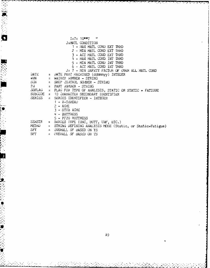
I=7: 10**7 "J =MATL CONDITION
I - MAX MATL COND EXT THRD2 - MIN MATL COND EXT THRD3 - ACT MATL COND EXT THRD4 - MAX MATL COND INT THRD5 - MIN MATL COND INT THRD
. 6 - ACT MATL COND INT THRDJ= 7 - MIN SAFETY FACTOR OF OVER ALL MATL COND
DATE = DATE PART MACHINED (ddmimyy) INTEGERWVN = WAIVER NUMBER - STRINGSCN = SHOP 2ONTROL NUIABER - STRINGPA = PART NUMBER - STRINGSDFLAG = FLAG FOR TYPE OF ANALYSIS, STATIC OR STATIC + FATIGUESUBCODE = 10 CHARACTER SECONDARY IDENTIFIERSERIES = SERIES IDENTIFIER - INTEGER
I - V-THREAD2 - ACME3 - STUB ACME4 - BUTTRESS5 - PF20 BUTTRESS
SERSTR = SERIES tYPE (UNC, BUTT, UNF, ETC.)METHD = STRING DEFINING ANALYSIS MODE (Static, or Static+Fatigue)SFY = OVERALL SF BASED ON YSSFT = OVERALL SF BASED ON TS
A9
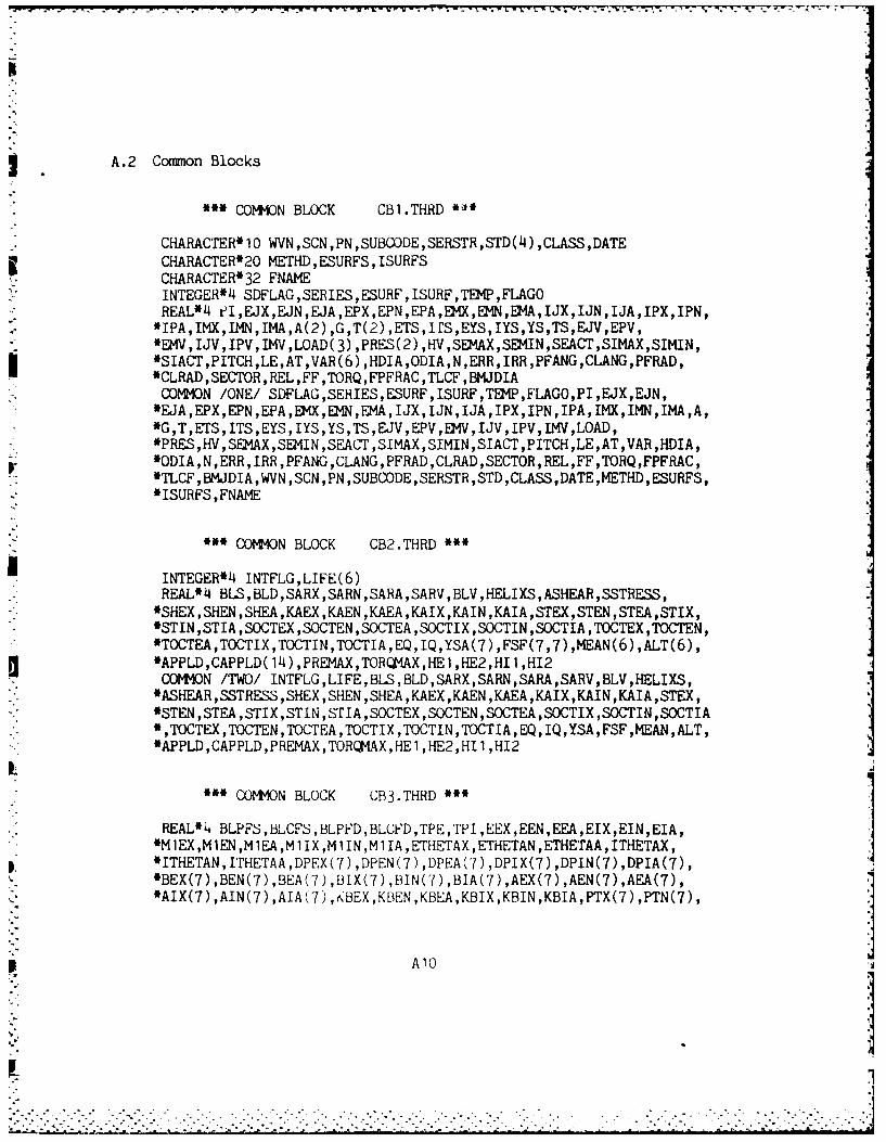
A.2 Common Blocks
~'COMMON BLOCK CBI.THRD '
CHARACTER*10 WVN,SCN,PN,SUBCODE,SERSTR,STD(4),CLASS,DATE5 CHARACTER*20 METHD ,ESURFS ,ISURFS
CHARACTER32 FNAMEINTEGER*)4 SDFLAG ,SERIES ,ESURF, ISURF ,TEMP ,FLAGOREALILI el,EJX,EJN,EJA,EPX,EPN,EPA,EM1X,EM4N,EKIA,IJX,IJN,IJA,IPX,IPN,*IPA,IMX,IMN,IEMA,A(2) ,G,T(2) ,ETS,IrS,EYS,IYS,YS,TS,EJV,EPV,*EMV,IJV,IPV,IMV,LOAD(3) ,PRES(2) ,HV,SE2IAX,SEIIN,SEACr,SIMAX,SIMIN,*SIACT,PIETCH,LE,AT,VAR(6),HDIA,ODIA,N,ERR,IRR,PFANG,CLANG,PFRAD,
*CLRAD,SECTOH ,REL,FF,TORQ ,FPFRAC ,TLCF ,BMJDIACOMMO3N /ONE! SDFLAG,SERIES,ESURF,ISURF,TEWI,FLAGO,PI,EJX,EJN,*EJA,EPX,EPN,EPA,EMVX,EMN,EMA,IJX,IJN,IJA,IPX,IPN,IPA,IM,IMN,IMA,A,*G,T,ETS,ITS,EYS,IYS,YS,TS,EJV,EPV,EM1V,IJV,IPV,IMV,LOAD,*PRES,HV,SEKIAX,SEM4IN ,SEACT,SIMAX,SIMIN,SIACT,PITCH,LE,AT,VAR,HDIA,
Ir *ODIA,N,ERR,IRR,PFANG,CLANG,PFRAD,CLRAD,SECTOR,REL,FF,TORQ,FPFRAC,*ThCF,BM.JDIA,WVN,SCN,PN,SUBGODE,SERSTR,STD,CLASS,DATE,METHD,ESURFS,*ISURFS ,FNAME
SCOMMO'KN BLOCK CB2.THRD *
INTEGER*I INTFLG,LIIFE(6)REAL*4 BLS,BLD,SARX,SARN,SARA,SAHV,BLV,HELIXS,ASHEAB,SSTRESS,
*SHEX,SHEN,SHEA,KAEX,KAEN,KAEA,KAIX,KAIN,KAIA,STEX,STEN,STEA,STIX,*STIN ,STIA ,SOCTEX,SOCTEN,SOCTEA ,SOCTIX ,SOCTIN,SOCTIA ,TOCTEX,TOCTEN,*TOCTEA,TOCTIX,TOCTIN,TOCTIA,EQ,IQ,YSA(7) ,FSF(7,7),MEAN(6) ,ALT(6),*APPLD,CAPPLD( 14) ,PREMAX,TORQ'4AX,HE1 ,HE2,HI1 ,H12COMMO0N /TWO/ INTFLG,LIFE,BLS,BLD,SARX,SABN,SARA,SARV,BLV,KELIXS,'ASHEAR,SSTRESS,SHEX,SHEN ,SHEA ,KAEX,KAEN,KAEA,KAIX,KAIN,KAIA,STEX,*STEN,STEA,STIX,STIN,STIA,SOCTEX,SOCTEN,SOCTEA,SOCTIX,SOCTIN,SOCTIA,TOCTEX,TOCTEN,TOCTEA,TOCTIX,TOCTIN,TOCTIA,EQ,IQ,YSA,FSF,MEAN,ALT,
*APPLD,CAPPLD,PREMAX,TORQ1AX,HE1 ,HE2,HI1 ,HI2
I-"COMM'ON BLOCK CB3.THRD ~
REAL*4 BLPFS,BLCFS,BLPFD,BLCFD,TPE,TIPI,EEX,EEN,EEA,EIX,EIN,EIA,*MlEX,MlEN,MlEA,MlIX,M1IN,MlIA,E-THETAX,ETHETAN,ETHETAA,ITHETAX,
* 'ITHETAN,ITHETAA,DPEX(7),DPEN(7),DPEA(7I),DPIX(7),DPIN(7),DPIA(7),*BEX(7) ,BEN(7) ,BEA(7) ,BIX(7) ,BIN(7) ,BIA(7) ,AEX(7) ,AEN(7) ,AEA(7),*AIX(7),AIN(7),AIA(7) ,KBEX,KBEN,KBEA,KBIX,KBIN,KBIIA,PTX()PTN()
p A10
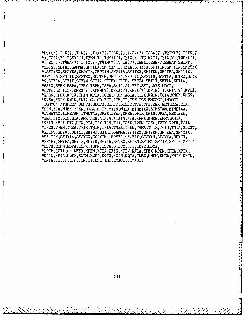
*PTA(7) ,T1X(7) ,TlN(7) ,TlA(7) ,T2EX(7) ,T2EN(7) ,T2EA(7) ,T2IX(7),T2IN(7*),T21A(7) ,T3EX(7) ,T3EN(7) ,T3EA(7) ,T3IX(7) ,T3IN(7) ,T3IA(7) ,T4EX(7),*T4EN(7) ,T4EA(7) ,TIIIX(7) ,TI4IN(7) ,T41A(7) ,SBEXT,SBENT,SBEAT,SBIXT,*SBINT,SBIAT,GAI4IA,SFlYEX,SFlYEN,SFlYEA,SFlYIX,SFlYIN,SF1YIA,SF2YEX*,SF2YEN,SF2YEA,SF2YIX,SF2YIN,SF2YIA,SFlTEX,SFlTEN,SFlTEA,SFlTIX,*SFlTIN ,SFlTIA,SF2TEX,SF2TEN,SF2TEA,SF2TIX,SF2TIN,SF2TIA,SFYEX,SFYE*N ,SFYEA,SFYIX,SFYIN,SFYIA,SFTEX,SFTEN,SFTEA,SFTIX,SFTIN,SFTIA,*ESPX,ESPN,ESPA,ISPX,ISPN,ISPA,S( 12,2) ,SFY,SFT,LDYE,LDYI,*LDTE,LDTI,CR,KFEX(7) ,KFEN(7) ,KFEA(7) ,KFIX(7) ,KFIN(7) ,KFIA(7) ,KPEX,*KPEN,KPEA,KPIX ,KPIN,KPIA,KQEX,KQEN ,KQEA,KQIX,KQIN,KQIA,KNEX,KNEN,*KNEA,KNIX,KNIN,KNIA,CL,CD,ECF,ICF,CT,ESE,ISE,E4XOCT,IMXOCTCOMMO~N /THRE~E/ BLPFS,BLCFS,BLPFD,BLCLD,TPE,TPI,EEX,EEN,EEA,EIX,*EIN,EIA,MlEX,MlEN,MlEA,MlIX,MlIN,MlIA,ErHETAX,ETHETAN,ETHETAA,*ITHETAX, ITHETAN ,ITHETAA ,DPEX,DPEN,DPEA,DPIX,DPIN,DPIA,BEX,BEN,*BEA,BIX,BIN,BIA,AEX,AEN,AEA,AIX,AINJ,AIA,KBEX,KBEN,KBEA,KBIX,*KBIN,KBIA,PTX,PTN,PTA,TlX,TlN,TlA,T2EX,T2EN,T2EA,T2IX,T2IN,T2IA,*T3EX,T3EN,T3EA,T3IX,T3IN,T3IA,T4EX,T4EN,TI4EA,T4IX,T4IN,T4IA,SBEXT,*SBENT ,SBEAT ,SBIXT,SBINT ,SBIEAT ,GAWMA,SFlYEX,SFlYEN,SFIYEA ,SF1YIX,'SF1 YIN ,SF1 YIA ,SF2YEX , Si2YEN ,SF2YEA ,SF2YIX ,SF2YIN ,SF2YIA ,SFYEX,*SFYEN ,SFYEA ,SFYIX, SFYIN ,SFYIA, SFTEX ,SFT~EN ,SFTEA ,SFTIX ,SFTIN ,SFTIA,*ESPX,ESPN,ESPA,ISPX,ISPN,ISPA,S,SFY,SFT,LDYE,LDYI,*LDTE,LDTIE,CR,KFEX,KFEN,KFEA,KFIX,KFIN,KFIA,KPEX,KPEN,KPEA,KPIX,*KPIN,KPIA ,KQEX,KQEN,KQEA,KQIX,KQIEN,KQIA,KNEX,KNEN,KNEA,KNIX,KNIN,*KNIA,CL,GD,ECF,ICF,CT,ESE, ISE,EMXOCT,IMXOGT
All
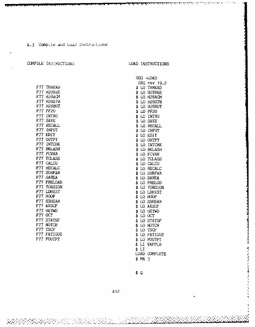
A.3 Compile drid Lodd Instructions
COMPILE INSTRUCTIONS LOAD INSTRUCTIONS
SEG -LOADSEG rev 19.2
F77 THREAD $ LO THREADF77 H2dVEE $ LO H28VEEF77 H28ACM $ LO H28ACMF77 H26SrB $ LO H28STBF77 H28BUT $ LO H28BUTF77 PF20 $ LO PF20F77 INTRO $ LO INTROF77 SAVE $ LO SAVEF77 RECALL $ LO RECALLF77 INPUT $ LO INPUTF77 EDIT $ LO EDITF77 OUTPT $ LO OUTPTF77 INTCHK $ LO INTCHKF77 BKLASH $ LO BKLASHF77 PCVAR $ LO PCVARF77 TCLASS $ LO TCLASSF77 CALCU $ LO CALCUF77 HECALC $ LO RECALCF77 SURFAR $ LO SURFARF77 SAREA $ LO SAREAF77 PRELOAD $ LO PRELODF77 TORSION $ LO TORSIONF77 LDHIST $ LO LDHISTF77 HOOP $ LO HOOPF77 SSHEAR $ LO SSHEARF77 AXSCF $ LO AXSCFF77 HEYWD $ LO HEYWDF77 OCT $ LO OCTF77 STATSF $ LO STATSFF77 NOTCH $ LO NOTCHF77 TSCF $ LO TSCFF77 FATIGUE $ LO FATIGUEF77 FOUTPT $ LO FOUTPT
$ LI VAPPLB$ LILOAD COMPLETE$MA 3
$Q
A12
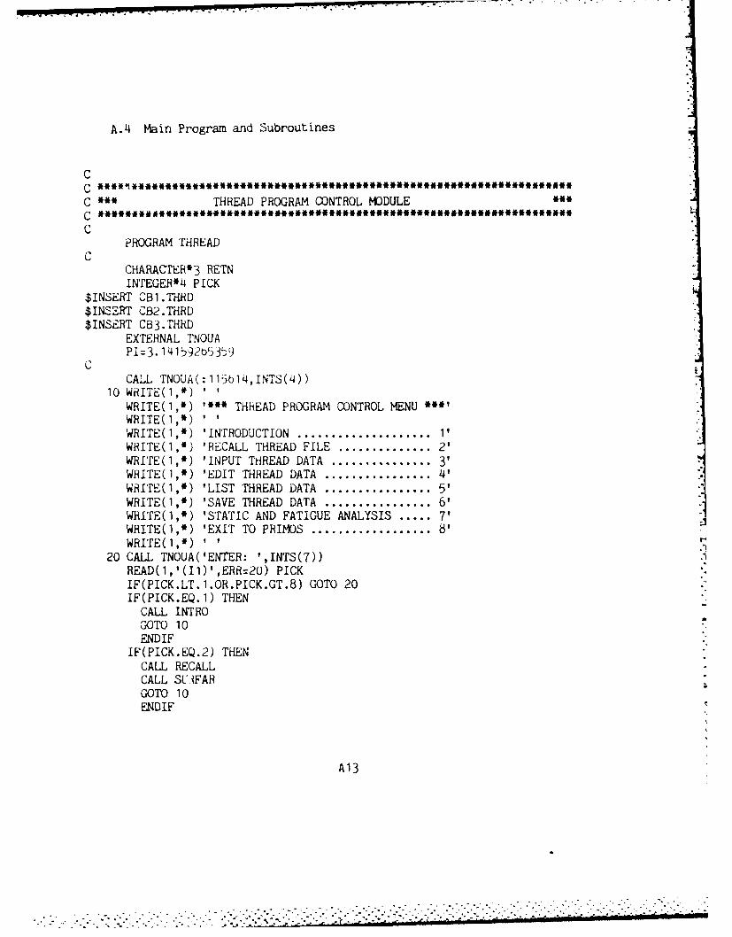
A.4 Main Program and Subroutines
C
C * THREAD PROGRAM CONTROL MODULEC ***.**************************#******eM*********************C
PROGRAM THREADC
CHARACTER*3 RETNINTEGER*4 PICK
$INSERT CBI.THRD$INSERT CB2.THRD$INSERT CB3.THRD
EXTERNAL TNOUAPI:3.14159205359
CALL TNOUA(:115b14,INTS(4))10 WRITE(1,*) '
WRITE(1,*) "* THhEAD PROGRAM CONTROL MENU **WRITE(1,*)WRITE(I,*) 'INTRODUCTION .................... 'WRITE(1,*) 'RECALL THREAD FILE .............. 2'WRITE(1,*) 'INPUT THREAD DATA ............... 3'WRITE(I,*) 'EDIT THREAD DATA ................ 4'
WRITE(1,*) 'LIST THREAD DATA ................ 5'WRITE(I,*) 'SAVE THREAD DATA ................ 6'WRITE(1,*) 'STATIC AND FATIGUE ANALYSIS ..... 7'WRITE(1,*) 'EXIT TO PRIMOS .................. 8'
WRITE(I,*) I I .1
20 CALL TNOUA('ENTER: ',INTS(7))READ(1,'(11)',ERR=20) PICKIF(PICK.LT.l.OR.PICK.GT.8) GOTO 20IF(PICK.EQ.1) THEN
CALL INTROGOTO 10ENDIF
IF(PICK.EQ.2) THENCALL RECALLCALL SLiFARGOTO 10ENDIF
A13
. . . . .. . . . . • .-. ... .. . .--. .-. . . , . . . .- -. -, -' "
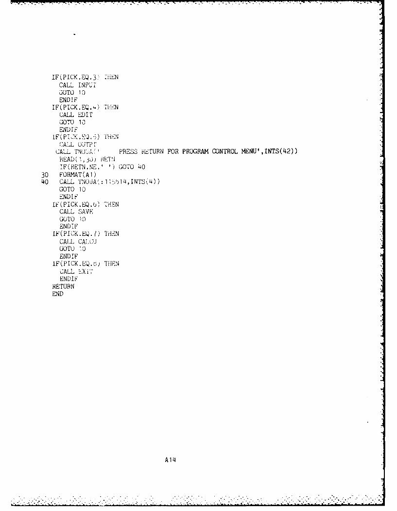
IF(PICK.EQ.3 liiENCALL INPUTGOTO 10ENDIF
IF(PICK.EQ.L;) TilrNCALL EDITGOTO 10ENDIF
IF(PIC:K-EQ.-.) TENCAlL OUTP F
CALL. TNO UA(' PRESS RETURN FOR PROGRAM CONTROL MENU' ,INTS(k42))READ ( 1, ,30 RETNIF(RE'rN.NE.' 1) GOTO 40
30 FORMAT(A1)40 CALL TNOUA I:I1K514, INTS .4)
GOTO 10END IF~
IF(PICK.EQ.b) THENCALL SAVEGOTO 10ENDIF
IF(PICK.EQ.l) THi-NCALL CAL0CUGOTO 10ENDIF
IF(PICK.EQ.b5 THENCALL EXIT-ENDIF
RETURNEND
A14I
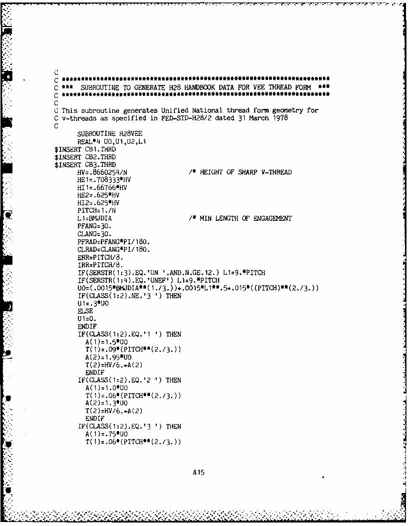
- . . - .7 Ir . -. - -7~-- -
CC ****~*I~*~**I******I*I*I****I*I***IC SUBROUTINE TO GENERATE H28 HANDBOOK DATA FOR VEE THREAD FORM
* ~~C ****4******~*#I**I*******E****** I
* CC This subroutine generates Unified National thread form geometry forC v-threads as specified in FED-STD-H28/2 dated 31 March 1978C
SUBROUTINE H28VEEREAL*4 UO,U1,U2,L1
$INSERT CB1.THRD$INSERT CB2.THRD$INSERT CB3.THRD
HV=.8660254/N /* HEIGHT OF SHARP V-THREADHE1=.708333*HVHI1=.66766*HV
* HE2=.625*HVH12=.625*HVPITCH=1 ./N
oL1=BMJDIA /* MIN LENGTH OF ENGAGEMENTPFANG= 30.CLANG: 30.PFRAD=PFANG*PI/ 180.CLRAD=CLANG*PI/ 180.ERR=PITCH/8.IRR=PITCH/8.IF(SERSTR(1:3).EQ.'UN '.AND.N.GE. 12.) L1=9.*PITCHIF(SERSTR(1:4).EQ.'UNEF') L1=9.*PITCHUO=( .OO15*BMJDIA**( 1./3.) )+.0015*Ll**.5+.015*((PITCH)**(2./3.))IF(CLASS(1:2).NE.'3 1) THENUl1= .3*U0ELSE
- - U1=0.ENDIFIF(CLASS(1:2).EQ.'1 ') THEN
* A(1)=1.5*UOT( 1)=.09*(PITCH**(2./3.))A(2)=1.95*UOT(2)=HV/6.+A(2)ENDIF
IF(CLASS(1:2).EQ.'2 ') THEN
* T( 1 ).06*(PITCH**(2./3.))A(2)=1.3*U0T(2)=HV/6.+A(2)ENDIF
IF(CLASS(1:2).EQ.'3 ') THENA( 1)=.75*UO
A15
6
A(2)= .975*U0T(2)=HV/6.+A(2)ENDIF
IF(BMJDIA.LT..25.AND.CLA~SS(1:2).NE.'3 1) THENU2= .05*(PITCH**(2 ./3.) )+.03*PITCH/BMJDIA-.0O2IF(U2.LT. .25*PITCH- .4PITCH**2.) U2=.25*PITCH- .'IPITCH**2.IF(U2.GT. .394*PITCH) U2= 39J4*PITCHGOTO 10ENDIF
IF(BMJDIA.GE..25.AND.CLASS(1:2).NE.'3 1) THENU2= .25*PITCH-. 4*PITCH**2.IF(N.LT.4.) U2=.15*PITCHGOTO 10ENDIF
U2= .05*(PITCH**(2./3. ))+.03*PITCH/BMJDIA-.002IF(N.LE.80.AND.N.GE.13.) THENIF(U2.LT. .23*PITCH-1 .5*PITCH**2.) U2= .23*PITCH-1 .5*PITCH"*2.ENDIF
IF(N.LE.12.AND.U2.LT..12O*PITCH) U2=.120*PITCHIF(U2.GT. .394*PITCH) U2= 394*PITCH
10 EJX=BMJDIA-UlEJN=EJX-T( 1)EPX=BMJDIA-2.*( .375*HV )-U1EPN=EPX-A( 1)EM'X=BMJDIA-2.*(.7083333*HV )-U 1EMN=EMXIJN=EJX+U 1IJX=IJN+T (2)IPN=BKJDIA-2 . *( .375*HV)IPX=IPN+A (2)IMN=BMJDIA-2 . *( .625*HV)IMX=IMN+U2SEMAX=. 14338PITCHSEMIN= .0721 688*PITCHSIMAX=. 108253*PITCHSIMIN . 03608144PITCHEJX=AINT(EJX*10000.+.5)/ 10000.EJN=AINT(EJN*10000.+.5)/10000.EPX=AINT(EPX*10000.+.5)/10000.EPN=AINT(EPN*10000..+.5)/ 10000.EMX=AINT(ER1X*10000.+.5)/10000.EMN=AINT(EM1N*10000.+.5)/10000.IJXAINT(IJX*10000.+.5)/10000.IJN=AINT(IJN* 10000.+.5)/10000.IPX=AINT( IPX*10000.+.5)/10000.IPN=AINT(IPN*10000.+.5)/10000.IMX=AINT(IMX*10000.+.5)/10000.IMN=AINT(IMN*10000.+.5)/10000.RETURNEND
A16
CjC
C '~SUBROUTINE TO GENERATE H28 HANDBOOK DATA FOR ACMIE THREADS
C
SUBROUTINE H28ACMiHEAL*~4 STO
$INSERT CB1.THRD$INSERT CB2.THRD$INSERT CB3.THRD
PiTrCH=1./NPFANG=29 ./2.CL.ANG=29 ./2.PFRAD=PFANG*PI/1~80.CLRAD=CLANG*PI/ 180.HV=. 5*PITCH/TAN (PFRAD)IF(CLASS(1:2).EQ.'2G') THENEJX=BMJDIAEJN=BMJDIA- . 5*PITCHIPN=BKJDIA- . 5PITCHEPX=IPN- .008*BMJDIA** .5EPN=EPX- ( .030*PITCH** .5+. 006*BMJDIA** 5)IF(N.GT.10.) G=.010IF(N.LE.1O.) G=.020EMX=BMJDIA-PITCH-GEMN=EMX-1 .5*(.030*PITCH**.5+.006*BMJDIA**.5)IJN=BMJDIA+GIJX= IJN+OIPX=IPN+( .030*PITCH** .5+.0Q6*BMJDIA'* .5)IMB=BMJDIA-PITCHIMN=BMJDIA-P ITCHIMX=IMN+ .05*? ITCHERR=.06*PITCHIRR: .06*PITCHSEMAX=( .3707*PITCH- .259*G)/TAN(PFRAD)' .5SEMIN=SEMAX-.5*( .03*PITCH**.5+.006*BMJDIA**.5)STO=G-( .03'PITCH**.5+.006*BMJDIA** .5)IF(STO.GE.0.) THENSIMAX=(.3707r'IrGH-.259*G)/TAN(PFRAD)' .5SIMN=~SIMAX-STOELSESIMIN=( .3707*PITCH- .259*G)/TAN(PFRAD)' .5
* SIMAX=SIMIN-STOENDIF
GOTO 50
U A17
iL
ENDIFIF(CLASS(1:2).EQ.'3G') THEN
EJ X=BMJDIAEJN=BMJDIA- .05*PITCHIPN=BKJDIA- .5*PITCH.EPX=IPN- .006*BMJDIAI* .5EPN=EPX-( .01J4*PITCH**.5+.QO28*BMJDIA**.5)IF(N.GT. 10.) G=.010IF(N.LE.10.) G=.020EMX=BMJDIA-PITCH-GEMN=EMX-1.*5*( .014*PITCH**.5+.0O28*BMJDIA**.5)I IJN=BMJDI A+I3.1JX= IJN+GIPX=IPN+( .014PITCH**.5+.0028*BMJDIA**.5).IMB=BMJDIA-PITCHIMN=BMJDIA-PITCHIMX=IM+. 05*PITCHERH=.06*PITCHIRR=.06*PTCSEMAX=( .3707*PITCH-.259*G)/TAN(PFRAD)*.5SEMIN=SEMAX-.5*( .014*PITH**.5+.OO28IBMJDIA**.5)STO=G-( .0O28BJDIA** .5+.01J4*PITCH**.5)IF(STO.GE.0.) THENSIMAX=( .3707*PITCH-.259*G)/TAN(PFRAD)*.5SIMIN=SIMAX-STOELSESIMIN=( .3707*PITCH-.259*G)/TAN(PFRAD)*.5SIMAX=SIMIN-STOEND IF
GOTO 50ENDIF
IF(CLAS3(1:2).EQ.'~4G?) THENEJ X = BWDIAEJN=BMJDIA- .05*PITCH
IPN=BMJDIA- .t*PITCHEPX=IPN-.004*BlAJDIA**.5EPN=EPX-( .OIu*P!'rcH**.5+.0O2*BMJDIA**.5)
iF(N.LE. 10.~ )6=.020i IX=BMJDTA-PITCH-GFN=FMX-1.7* .010*PITCH**.5+.O2BMJDIA**.5)
IPX4IPN+( .010*PITCH*.5+.002*BJDIA.5)r-: M, iJ)A -P !I CH
A18
IMN=BMJDIA-PITCHIMX=IMN+ . 5*P ITCHERHR .06*PITcHIRR: .06*PITCHSEMAX: ( .3707*PITCH- .259*G)/TAN(PFRAD)*.5SEMIN=SEMAX- *( .O1QPITCH**.5+.0020*BMJDIAI**.5)STO=G-( .0020*BMDIA*.5+.010PITCH*'.5)IF(STO.GE.Q.) THENSIMAX: ( .3707*PITCH- .259*G)/TAN(PFRAD)*.5SIMIN=SIMAX-STOELSESIMIN: ( .3707*PITCH- .259*G)/TAN(PFRAD)*.5p SIMAX=SIMIN-STOEND IF
GOTO 50ENDIF
IF(CLASS(1:2).EQ.'2C') THENEJX=BMJDIAEJN=BMJDIA- .0035*BMJDIA** 5IPN=BMJDIA- . 5PITCHEPX=IPN- . 08*BMJDIA** 3EPN=EPX- ( .030*PITCHi** .5+. OO6*BMJDIA** .5)IF(N.GT.10.) G=.010IF(N.LE.10.) G=.020EMX=BMJDIA-PITCH-GEMN=EMX-1 .5*( .030*PITCH**.5+.006*BMJDIA**.5)LJN=BMJDIA+.001*BMJDIA** .5IJX=IJN+ .0035*BMJDIA** .5IPX=IPN+( .030*PITCH** .5+.006*BMJDIA**.5)IMB=BMJDIA-PITCHIMN=BMJDIA-PITGH+. 1*PITCHIMX=IM. 5*PITCHERR: .07*PITCHIRR: .07*PITCHSEMAX=( .3707*PITCH-.259*G)/TAN(PFRAD)*.5SEMIN=SEMAX- .5*( .30*PITCH** .5+.006*BMJDIAI**.5)STO: .0035*BMJDIA** .5-( .OO6*BMJDIAII .5+.O3*PITCH**.5)IF(STO.GE.0.) THENSIMAX: ( .3707*PITCH- .259w .001*BMJDIA** .5)/TAN(PFRAD)' .5SIMIN=SIMX-STOELSESIMIN=(.3707*PITCH-.259*.0Q1*BMJDIA**.5)/TAN(PFRAD)*.5SIMX=SIMIN-STOENDIF
GOTO 90
A19
ENDIFIF(CLASS(1:2).EQ.'3C') THEN
EJX=BMJDIAEJN=BMJDIA- .0015*BMJDIA** 5IPN=BMJDIA- .5*PITCH
EPX=IPN-.006*BMJDIA*.5EPN=EPX-( .01 4*PITCH** .5+.0028*BMJDIA** 5)IF(N.GT.10.) G=.010IF(N.LE.10.) G=.020EMX=BJDIA-PITCH-GEMN=EMX-1 .5*( .014*PITCH**.5+.0O28*BMJDIA**.5)IJN=BMJDIA+..001*BMJDIA**.5IJX=IJN+ .0035*BMJDIA** 5IPX=IPN+( .014*PITCH**.5+.0028BMJDIA**.5)IMB=BMJDI A-PITCHIMN=BMJDIA-PITCH+.l1*PITCHIMX=~IN+. 05*PITCHERR . 07*PITCHIRR=.07*PITCHSEMAX=( .3707*PITCH-.259*G)/TAN(PFRAD)*.5SEMIN=SEMAX-.5*( .014PITCH**.5+.0028*BMJDIA**.5)STOz .o035*BMJDIA** .5-( .0028*BMJDIA** .5-..014PITCH".5)IF(STO.GE.0.) THENSIMAX=(.3707*PITCH-.259*.01*BJIA**.5)/TAN(FRAD)*.5SIMIN=SIMAX-ST0ELSESIMIN=( .3707*PITCH-.259*.001*BMJDIA**.5)/TAN(PFRAD)*.5SIMAX=SIMIN-STOENDIF'
GOTO 90ENDI F
IF(CLASS(1:2).EQ.'J4C') THENEJX=BMJDIAEJN=BMJDIA- .001 'BMJDIA**.5IPN=BMJDIA- . 5PITCHEPX=IPN-.00)4*BKJDIA*.5EPN=EPX-( .0 10*PITCH** .5+ .002*BMJDIA**.5)IF(N.GT. 10.) G=.010.F(N.LE. 10.) G=.020EM1X=BMJDA-PITCH-GEM"N=EMX-1 .5*( .010#PITCH**.5+.002*BMJDIA**.5)
* IJN=BMJDIA-.001*BMJDIA**.5LJX=IJN+ .002*BMJDEA** *5fPX=IPN+( .010*PITCH**.5+.002*BMJDIA**.5)IMB=BMJDI A-P ITCH
A20
IMN=B~mjDIA-PTTCH+. 1 PITCHIMX=IMN+ 05*P ITCHERR . 07*PITCHIRR= .07*PITCHiSEMAX=( .3707*PITCH-.259*G)/TAN(PFRAD)*.5SEMIN=SEMAX- .5' (.010*PITCH**.5+.002*BMJDIA**.5)STO: .002*BMJDIA**.5-C .002*BMJDIA**.5+.01*PITCH**.5)IF(STO.GE.0.) THENSIMAX=( .3707*PITCH- .259' .001*BMJDIA**.5)/TAN(PFRAD)' .5SIMIN=SIMAX-STOELSESIMIN=( .3707*PITCH- .259' .001*BMJDIA**.5)/TAN(PFRAD)' .5SIMAX=SIMIN-STOENDIF
GOTO 90ENDIF
IF(CLASS(1:2).EQ.'5C') THENEJX=BMJDIA-.025*BMJDIA**.5 I' BEJN=EJX- .001 5*BMJDIA* .5IPN=EJX- .5*PITCHEPX: IPN- .008*BMJDIA**.5EPN=EJX-( .0ILI*PITCH*' .5+.0028*BMJDIA" .5)IF(N.GT.10.) G=.010IF(N.LE.10.) G=.020EMX=EJX-PITCH-GEMN=EMX-1 .5*( .014PITCH*.5+.0028*BMJDIA**.5)IJN=EJX+ .001 'BMJDIA" .5IJX=IJN+ .0035*BMJDIA**.5IPX=IPN+( .014PITCH**.5+.0028*BMJDIA**.5)IMB=EJX-PITCHIMN=EJX-PITCH+.l1 PITCHIMX=IMN+ .05*PITCHERR: .07*PITCHIRR: .07'PITCHSEMAX= C. 3707*PITCH- .259*G)/TAN(PFRAD)' .5SEMIN=SEMAX-.5*( .014*PITCH**.5+.0028*BMJDIA**.5)STO: .0035*BMJDIA**.5-( .0028*BMJDIA" .5+.014*PITCH**5)IF(STO.GE.0.) THENSIMAX=( .3707*PITCH-.259*.001*BMJDIA"*.5)/TAN(PFRAD)*.5SIMIN=SIMAX-STOELSESIMIN=( .3707*PITCH-.259*.001'BMJDIA"*.5)/TAN(PFRAD)*.5SIMAX=SIMIN-STO
END IFGOTO 90
A2 1
. . . . . ... . . . . . . . .. . .
ENDIF
IF(CLAS~s(1:2).EQ-'b'C') THENEJX=BMJDIA- .025*BMJDIA**.5
EJ N= EJX- . 00 10 * BIJ DIA* 5IPN=EJX- .5*PITCHEPX=IPN-.006*BMJDIA**.5EPN=EJX-( .01U*PITGH**.5+.002*BMJDIA**.5)IF(N.GT. 10.) G=.010IF(N.LE.10.) ;.020EMX=EJX-P ITCHi-CEMN=EMX.-1 .5*' .010*PITCH*.5+.002*BMJDIA*.5)IJN=EJX+ . GO 1 *B.NJDIA**. 5IJX=IJN+. 002*JMJUDlA** .5IPX=IPN+(.iJ'*Pi-TOH**.5+.002*BMJDIA**.5)IMF3=EJX-P ETURIMN=EJX-Pi'j - I *PITCH
IM[M'-"+. 5*P ITACHERfRf=- 7*PIT(N-4 a.I RR J7 * P", "-HSEMAX=( .3'7J/',*PTCH-.259*G)/TAN(PFRAD)*.5SEMIN=SEMAX-.5*( .01*PITCH**.5+.002*BMJDIA*.5)STO- 002*BKJDI)A** .5-( .002*BMJDIA**.5+.01O*PITCH*-.5))
SIMAX(- I')7 TCH-. 259*.01 *BM4JDI#* .5) /TAN (PFRAD)*. 5S I MIN::S I MAX-SDTOELSES11 . )7PfK .A9.001*BMJDIA**.5)/TAN(PFRAD)*.5SIMAX :iMI-$FUS
rollIF
ENDIF50 HE2=. 11,11
HE I HE,)+.KHI 1zHElGOTO 100
90 HE2=.U3*PlT,,lii
HE 1 HE +. L-*_iHI I1=HIL +. 5*ITC
100 EJX=AlfNTr(E-JX* 1 + .. 5) /10000.EJN=AINT (EJ4* 1 00~~5)/i10000.EPX-AINT(F'UX*10000.+.5)/ 10000.EPN=AINTF(i2-N* loooo.-..5)/10ooO.
ENXV(A INT (EMX* 1000i0. +. )10000.
A22
- -5-In -- - - - - - - - - -
EMN=AINT(FE1N*10OOO.+.5)/1000O.IJX=AINT(IJX*10OOO.+.5)/10OOO.IJN=AINT(IJN*10000.+.5)/10000.IPX=AINT(IPX*10000.+.5)/10000.IPN=AINT(IPN*10000.+.5)/10000.IMX=AINT(IMX*10000.+.5)/10000.IMN=AIN'r(IMN*10000.+.5)/10000.RETrURNEND
A2 3]
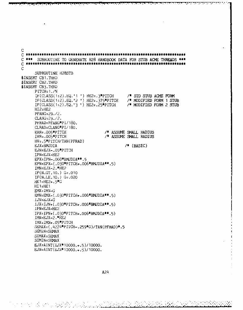
C
C * SUBROUTINE TO GENERATE H28 HANDBOOK DATA FOR STUB ACME THREADS '
C
SUBROUTINE HI28STB$INSERT CB1.THRD$INSERT CB2.THRD$INSERT CB3.THRD
PITCH= 1./NIF(CLASS(1:2).EQ.'11' HE2=.3*PITCH /* STD STUB ACME FORMIF(CLASS(1:2).EQ.'2 ')HE2=.375*PITCH 1* MOJDIFIED FORM 1 STUBIF(CLAS.S(1:2).EQ.'3 ')HE2=.25*PITCH /* MODIFIED FORM 2 STUBH12=HE2PFANG=29 ./2.CLANG=29./2.PFRAD=PFANG*PI/ 180.CLRAD=CLANG*PI/ 180.ERR=.005*PITCH 1* ASSUME SMALL RADIUSIRR=.005*PITCH /* ASSUME SMALL RADIUSHV .5*P ITCH/TAN (PFRAD)EJX=BMJE)IA I' (BASIC)EJN=EJX- .O5*P ITCHIPN=EdX-HE2EPX=IPN-.0O8*BMJDIA**5EPN=EPX- ( .030*PITCH+ .006*BMJDIA*5)
IMN=EJX-2. *HE2
IF(N.LE. 10.) G=.020HEl=HE2+.5*GHI1=HE1EMX=IMN-GEMN=EMX-( .030*PITCH+.o06*BMJDIA** 5)I JN =EJX+GIJX=IJN+( .030*PITCH+.006*BMJDIA** 5)IPN=EJX-HE2IPX=IPN+( .030*PITCH+.006*BMJDIA'* .5)IMN=EJX-2 .*iIMX=IMN+.O5*P ITCH'SEP AX=(.4224*PITCH .259*G)/TAN(PFRAD)* *5SEMI N=SEMAXSIMAX=SEMAXSIMIN=SEMAXEJX=AINT(JX*10000.+.5)/10000.EJN=AINT(JN*10000.+.5)/1Q000.
A214
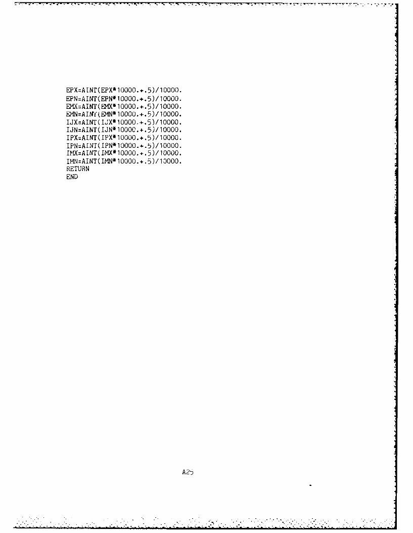
EPX=ATNr(EPX*10000.+.5)/ 10000.EPN=AINT(EPN*10000.+.5)/100O0.EMX=AINT(D9I*10000.+.5)/100O0.EMN=AINf'f(EMN* 10000.+.5)/10000.IJX=AINT(IL.X*10000.+.5)/10000.IJN=AINT(IIJN* 1000C.+.5)/ 10000.IPX=AINT(IPX*10000.+.5)/10000.IPN=AINT( IPN*10000.+.5)/10000.IMX=AINT( IMX* 10000.-..5)/ 10000.IMN=AINT(IMN*10000.+.5)/ 13000.RETURNEND
A25
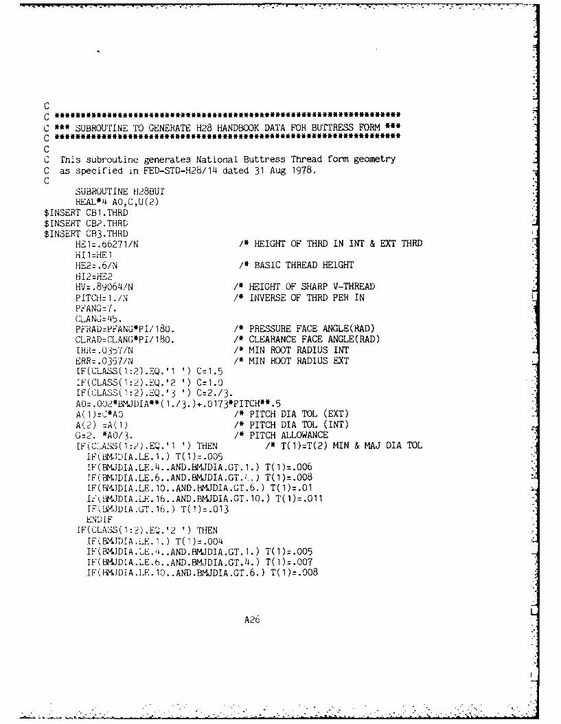
CC ***~****************************
C SUBROUTINE TO GENERATE H28 HANDBOOK DATA FOR BUTTRESS FORM "
C **g*****************************
CC This subroutine generates National Buttress Thread form geometryC as specified in FED-STD-H28/14 dated 31 Aug 1978.C
SUBROUTI NE H28BUrREAL*L4 AO,C,U(2)
$INSERT CB1.THRD$INSERT CB2.THRD$INSERT CB3.THHD
HE1=.0'6271/N 1* HEIGHT OF THRD IN INT & EXT THRDHI1=HE1HE2=.6/N /* BASIC THREAD HEIGHTH12=HE2HV=.89064/N /* HEIGHT OF SHARP V-THREADPITCH=1./N /* INVERSE OF THRD PER INPFANG=7.CLANGZ 45.PFRAD=PFANG*PI/180. /* PRESSURE FACE ANGLE(RAD)CLRAD=CLANG*PI/180. /* CLEARANCE FACE ANGLE(RAD)IHHR .0357/N /* MIN ROOT RADIUS INTERR=.0357/N /* MIN ROOT RADIUS EXTIF(CLASS(1:2).EQ.'11' C=1.5IF(CLA&SS(1:2).EQ.'2 1) C=1.0IF(C-LAo'S(1:2).EQ.'3 1) C=2./3.AO=.002*BMJDIA**(1./3.)+.0173*PITCH**.5A(1)=C*AO /* PITCH DIA TOL (EXT)A(2) =A(l) /* PITCH DIA TOL (INT)G=2. *AO/3. /* PITCH ALLOWANCELF(CLA3S(1:2).EQ.'1 ') THEN /* T(1)=T(2) MIN & MAJ DIA TOLIF(BM.JDIA.LE.1.) T(1)=.005IF(BMJDIA.LE.4. .AND.BMJDIA.GT. 1.) T(1 )=.OO6IF(BMJDIA.LE.6..AND.BMJDIA.GT.) .) T(1)=.008
Ir'(J3MDIA.LE.1..AND.BMJDIA.GT.10.) T(1)=.011IF'U3MJDIA.GT.16.) T(1)=.013ENDIF
1F(CLA3S(1:2).EQ.'2 ') THEN
IW(BJDIA.LE.24..AND.BMJDIA.GT.1.) T(1)=.005IF(BMJDIA.LE.6. .AND.BMJDIA.GT.4.) T(1)=.0O7IF(PM.JDIA.LE.1Q..AND.BMJDIA.GT.6.) T(1)=.008
A26
. 6 .
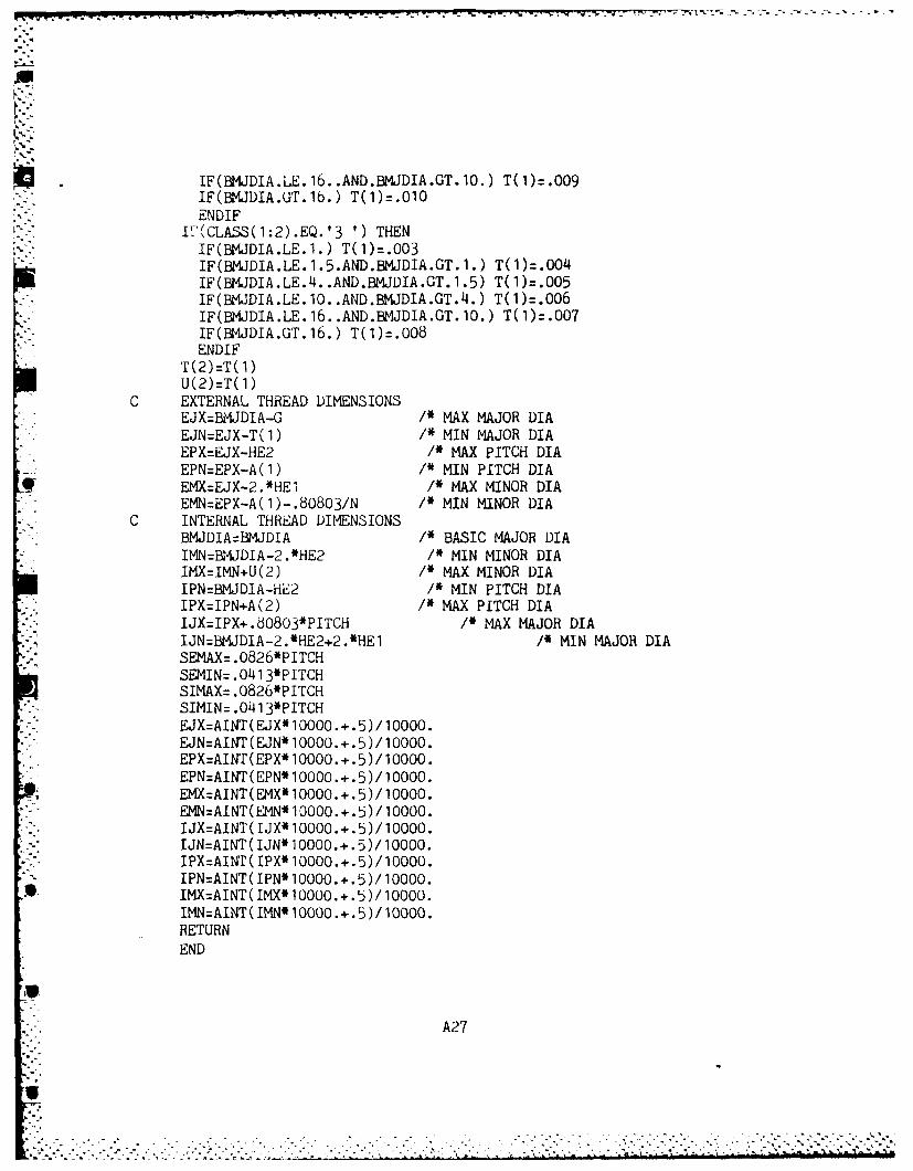
IF(BMJDIA.LE. 16. .AND.BMJDIA.GT.1O.) T(1)=.009IF(BMJDIA.GT.1b.) T(1)=.010ENDIF
I"(CLASS(1:2).EQ.'3 ') THEN- - ~~IF(BMJDIA.LE.1.5.TA1D.003AGT1)T().0
IF(BMJDIA.LEJ. .AND.BMJDIA.GT.1.) T(1)=.004IF(BMJDIA.LE.1O..AND.BMJDIA.GT.14.) T(1)=.006
* IF(BMJDIA:LE: 16:.AND.BMJDIA.GT.10.) T(1)=.006
ENDIFT(2)=T( 1)U(2)='r(l)
C EXTERNAL THREAD DIMENSIONS / A AO I
EJN=EJX-T(l) /* MIN MAJOR DIAEPX=EJX-HE2 /* MAX PITCH DIAEPN=EPX-A(l) /* MIN PITCH DIA
tEMX=EJX-2.*HE', /* MAX MINOR DIAEMN=EPX-A(l)-.80803/N /* MIN MINOR DIA
* -. C INTERNAL THREAD DIMENSIONSBMJDIA=BMJDIA /* BASIC MAJOR DIAIMN=BMJDIA.-2.*HE2 /* MIN MINOR DIAIMX=IMN+U(2) /* MAX MINOR DIAIPN=BMIJDIA-HE2 /* MIN PITCH DIA
*IPX=IPN+A(2) /* MAX PITCH DIAIJX=IPX+.83O8O3*PITCH /* MAX MAJOR DIAIJN=BMJDIA-2.*HE2+2.*HEl /* MIN MAJOR DIASEMAX= .0826*PITCHSEIN= .041 3*PITCHSIMAX= .0826*P ITCHSIMIN= .041 3*PITCHEJX=AINT(EJX*1000O.+.5)/10OO0.E.JN=AINT(E.JN*10000.+.5)/10000.EPX=AIN'T(EPX*10000.+.5)/10000.EPN=AINT(EPN*10000.+.5)/10000.EMX=AINT(EMX*10000.+.5)/10000.EMN=AINT(EMN*10000.+.5)/10000.
* . IJX=AINT(IJX*10000.+.5)/10000.IJN=AINT(IJN*10000.+.5)/10000.IPX=AINT(IPX*10O00.+.5)/10000.IPN=AINT(IPN*10000.+.5)/10000.
* IMX=AINT(IMX*10000.+.5)/10000.IMN=AINT(IMN*10000.+.5)/10000.RETURNEND
lip
A27
CC **********i******i**a***u**i*
C '~SUBROUTINE TO GENERATE PF20 WTV BUTT1RESS THREAD FORM '
* CC This subroutine generates special 20 deg. pressure flank ButtressC thread form designed by Waterviet Arsenal.C In this subroutine Datum Dia.=Pitch Dia.=BMJDIA
* CSUBROUTINE PF20
INTEGER*4 PICK$INSERT CB1.THRD$INSERT CB2.THRD$INSERT CB3.THRD
PFANG=20.CLANG=45.PFRAD=PFANG*PI/ 180.
CLRAD=CLANG*PI/ 180.WRITE(1,*) 'PITCH=0.250 ................... 1'WRITE(1,*) 'PITCH=0.375 ................... 2'WRITE(1,*) 'PITCH=0.500O...................3'
*-WRITE(1,*) 'PITCH=O.750 ................... 1'2 CALL TNOUA('SELECT PITCH: ',INTS(114))
READ(1,'(12)',ERR=2) PICKIF(PICK.LT.1..OR.PICK.GT.4) GOTIO 2IF(PICK.EQ.1) THEN
PITCH=0. 250N=1 ./PITCHHV=0. 1833SEMAX= .0142/(1 .+TAN(PFRAD))SEMIN= .037/(1 .+TAN(PFRAD))SIMAX=SEMAXSIMIN=SEMINERR=0. 0327IRR=0.0327EPX=BMJDIA
0 EPN=EPXEJX=EPX+0. 101EJN=EJX-0.005EMX=EPX-0. 139EMN=EMX-0.010IPX=EPXIPN=IPXIJN=IPX+0. 139IJX=IJN+0.010
A28
IMN=IPX-0. 101IMX=IMN+0. 00'tGOTO 100ENDL F
IFktPICK.EQ.2) THENPITCH=O. 375N=1 ./PITCHHV=0.2749SEt4AX=.061/(1 .+TAN(PFRAD))SEMIN=.056/(1 .+TAN(PFRAD))SIMAX=SEMAXSIMIN=SEMINERR=0. 045IRR=0.045EPX=BMJDIAEPN=EPXEJX=EPX+0. 151EJN=EJX-0. 005EM1X=EPX-0.208EM1N=EMX-0.010IPX=EPXIPN=IPXIJN=IPX+0 .208
IJX:IJN+0 .010IIIN=IPX-0. 151IMX=IMN+0 .005GOTO 100ENDIF
IF(PICK.EQ.3) THENPITCH=0.500N=1 ./PL'TCHHV=0. 3666SEMAX=.079/( 1.+TAN(PFRAD))
* SEMIN=.07L4/(l.+TAN(PFRAD))* SIEMAX=SEMAX
SILMIN=SEMINERH=0.061IRRz 0.061EPX =BMJDI AEPN=EPXi&JX=EPX+0.202FEJN=EJX-O .005
* EMX=EPX-0.278EMN=EMX-0.010IPX=EPX
A29
IPN=IPXIJN=IPX+0. 278IJX=IJN+0 .010IMN=IPX-0.202IMX=IMN+0 .005GOTO 100ENDIF
IF(PICK.EQ.14) THENPITCH=0.75N=1 ./PITCHHV=0.5499SEMAX=.117/(1 .+TAN(PFRAD))SEMIN=.112/(l.+TAN(PFRAD))SIMAX=SEMAXSIMIN=SEMINERR=0. 095IRR=0. 095
I- EPX=BMJDIAEPN=EPXEJX=EPX+0. 302E.JN=EJX-0. 005EMX=EPX-0.'416EM'N=EMX-0. 010IPX=EPXIPN=IPXIJN=IPX+0. 416IJX=IJN+0. 010IMN=IPX-0. 302IMX=IMN+0.005GOTO 100END IF
100 HE1=EJX-EMNHI1=HElHE2=EJX-IMH12=HE2RETURNEND
A30
~~~. . . .= .- . .i T-7 V -T I, - : -,. • m . 2| : m Z
C
C *** INTRODUCTION *
C
SUBhJUTINE INTROC
CHARACTER CONT1 ,CONT2* EXTERNAL TNOUA
.- -CALL TNOUA(:115614,INTS(4))'" WRITE(1,*)
WRITE(1,*)*WRITE(1,*) ' This is a thread stress analysis program which soIv
*es static and fatigue'
WRITE(1,*) '(simple load history) problems under assumption of ela'sticity.'WRITE(1,*) '
WRITE(1,*) ' Standard thread form data of V thread (UN, UNC,UNF*and UNEF), Acme thread,'WRITE(1,*) 'stub Acme thread and Buttress thread are generated ace*ording to FED-STD-H28
* WRITE(I,*) 'screw thread handbook. Special thread form data of PF*20 thread are generated
*- WRITE(1,*) 'per design specification provided by Watervliet Arsena
WRITE(1,*) '
- WRITE(1,*) ' In static analysis, load capacity of threaded joint" * and safety factors are I
WRITE(1,*) 'calculated under maximum, minimum and actual material*conditions corresponding IWRITE(1,*) 'to yield stress and tensile strength. In fatigue anal
*ysis, safety factorsWRITE(1,*) 'corresponding to various fatigue life cycle ranges are
" estimated base on userWRITE(1,*) 'supplied input information.'WRITE(1,*)WRITE(1,*) '
WRITE(1,*)WRITE(1,*) 'CALL TNOUA(' PRESS RETURN TO CONTINUE',INTS(29))READ(1,10) CONTIIF(CONT1.NE.' ') GOTO 50
10 FORMAT(Al)50 CALL TNOUA(:115614,iNTS(4))
WRITE(I,') 'WRITE(1,*)WHITE(l,*) ' Required input information and examples are lis'ea
*as follow:'WRITE(1,'I) 1. Waiver no.: e.g. RIW1234'
A31
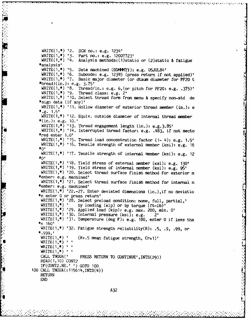
1-1
WRITE(I,*) '2. SCN no.: e.g. 1234'WRITE(1,*) '3. Part no.: e.g. 12007723'WRITE(1,*) '14. Analysis methods:(1)static or (2)static & fatigue*analysis'WRITE(1,*) '5. Date machined (DDMMMYY): e.g. 05JUL84'WRITE(1,*) '6. Subcode: e.g. 12345 (press return if not applied)'WRITE(1,*) '7. Basic major diameter (or dtaum diameter for PF20 t*hread)(in.): e.g. 3.75'WRITE(1,*) '8. Thread/in.: e.g. 6,(or pitch for PF20: e.g. .375)'WRITE(1,*) '9. Thread class: e.g. 2'WRITE(1,*) '10. Select thread form from menu & specify non-std de*sign data (if any)'WRITE(1,*) '11. Hollow diameter of exterior thread member (in.): e
*.g. 1.5'WRITE(1,*) '12. Equiv. outside diameter of internal thread member*(in.): e.g. 10.'WHITE(1,*) '13. Thread engagement length (in.): e.g.3.85'WRITE(1,*) '14. Interrupted thread factor: e.g. .483, if not secto
*red enter 1.0'WRITE(1,*) '15. Thread load concentration factor (1- 4): e.g. 1.5'WRITE(1,*) '16. Tensile strength of external member (ksi): e.g. 16*0'WRITE(1,*) '17. Tensile strength of internal member (ksi): e.g. 12*0'WRITE(1,*) '18. Yield stress of external member (Ksi): e.g. 130'WRITE(1,*) '19. Yield stress of internal member (ksi): e.g. 95'WRITE(1,*) '20. Select thread surface finish method for exterior m*ember: e.g. machined'WRITE(1,*) '21. Select thread surface finish method for internal m
*ember: e.g. machined'WRITE(1,*) '22.-27. Enter deviated dimensions (in.),if no deviatio*n enter 0 or press return'WRITE(1,*) '28. Select preload condition: none, full, partial,'WRITE(1,*) ' by loading (kip) or by torque (ft-lb)'WRITE(I,*) '29. Applied load (kip): e.g. max. 200, min. 0'WRITE(1,*) '30. Internal pressure (ksi): e.g. 2'WRITE(1,*) '31. Temperature (deg F): e.g. 180, enter 0 if less tha*n 160'WRITE(I,*) '32. Fatigue strength reliability(R): .5, .9, .99, or
*.999,'WRITE(1,*) ' (R=.5 mean fatigue strength, Cr=1)'WRITE(I,*) ' '
WRITE(1,*)WRITE(1,*)CALL TNOUA(' PRESS RETURN TO CONTINUE',INTS(29))READ(1,10) CONT2IF(OONT2.NE.' ') GOTO 100
100 CALL TNOUA(:115614,INTS(4))RETURNEND
A32
'I
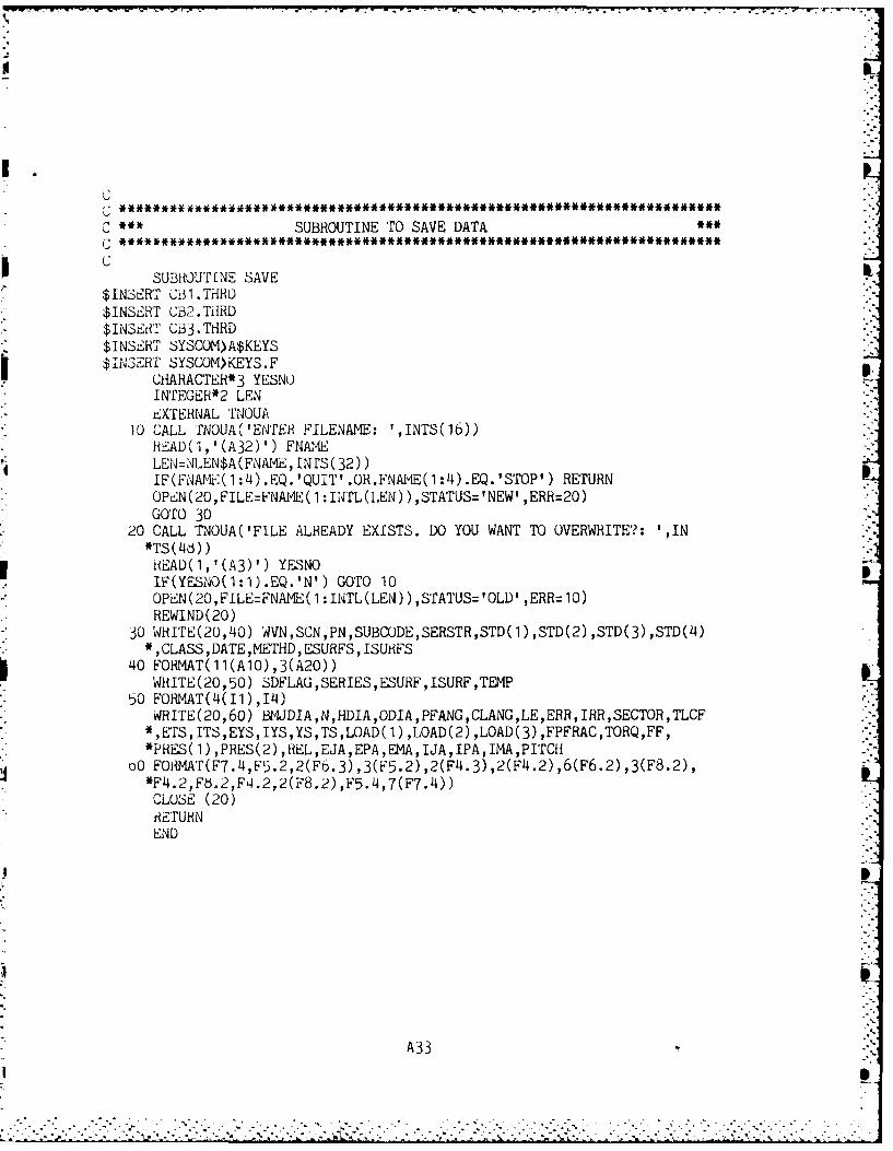
C '~ SUBROUTINE To SAVE DATA
SUBROUTI NE SAVE$INSERT C!3l.THRD$INSE~RT CB2-.TiiRD$IlNSElil CB3.TH-RD$INSERT SYSCOM)A$KEYS$INSERT SYSC;OM>KEYS.F
CHAHACTER*3 YESNUINrEGER*2 LENtEXTEHNAL 1YJOUA
10 CALL TNOUA (IENTERi FILENAME: ',INTS(16))HEAD(1,'(A32)') FNAMELEN=NLEN$A(FNAl4EIN'rs(32))IF(FNAMIE(1:4).EQ.'QUIT'.0R.FNAvE(1:4).EQ.'STfOP') RETURN0PiEN(20,FILE=FNAM-E(1 :iNT'L(LEN) ),STATUS='NEW' ,ERR=20)GOTO 30
20 CALL TNOUA('FILE ALREADY EXISTS. DO YOU WANT TO OVERWRITE'?: ',IN
3 RiEAD(l,'(A3)') YESNOIF(YESNO(1:1).EQ.'N') GOTO 10OPiEN(20,FILE=FNAME(1:INTL(LEN)),STfATUS='OLD' ,ERR=1O)REWIND(20)
* 30 WHITE(20,'40) WVN,SCN,PN,SUBCODE,SERSTR,STD(l),STD(2),STD(3),STD(4)* ,CLASS, DATE ,METHD ,ESURFS, ISURiFS
40 FORMAT(11(A10),3(A20))WRITE(20,50) SDFLAG ,SERIES, ESURF, ISURF ,TEMP
50 FORMAT(J4(Il),I4)WRITE(20,60) BMLIJDIA,N,HDIA,ODIA,PFANG,CLANG,LE,ERR,IRR,SECTOR,TLCF*,Ers,ITS,EYS,IYS,YS,TS,LOAD(l),LOAD(2),LOAD(3),FPFRAC,TORQ,FF,*PRiES(1) ,PRES(2) ,REL,EJA,EPA,EIMA,IJA,IPA,IMA,PITCH
oO FOdMT(F7.4,F5.2,2(F6'.3),3(F5.2),2(F4.3),2(F4.2),6(F6.2),3(F8.2),*F4.2,Fb.2,F4.2,2(F8.2),F5.4,7(F7.4))
CLOSE (20)iiETURNEND
A33
A
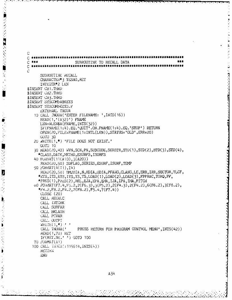
C
C SUBROUTINE TO RECALL DATAC
* CSUBROUTINE RECALLCHARACTER* 3 YESNO, RETINTLEGER*2 LEN
* $isET CB1I. THRD$INSERT C82.THRD$INSERT CB3.THHRD$INSERT SYSCOM>A$KEYS$ INSERT SYSCOM>KEYS. F
EXTERN4AL TNOUA10 CALL fNOUA('ENTER FILENAME: ',INTS(16))
or IREAD(1,'(A32)') FNAMELEN=NLEN$A (FNAME, INTrS(32))IF(FNAMIE(1:4).EQ.'QUIT'.OR.FNAME(1:14).EQ.'STOP') RETURNOPEN(20,F'ILE=FNAME( 1:INTL(LEN)),STATUS='OLD' ,ERR=20)GOf0 30
* 2U dflI'E(1,*) 'FILE DOES NOT EXIST.'3 GOTO0 1030 HEAD(20,40) vVN,SCN,PN,SUBCODE,SERSrFR,STD(l),STD(2),STD(3),STD(4),
*CLASS ,DATE ,ME'rHD ,ESURiFS, ISURFS40 FuRNI4T(11(Al0),3(A20))
READ(20, 50) SDFLAG ,SERIES ,ESURF, ISURF,TEMP
READ(20,60) BMJDIA,N,HDIA,ODIA,PFANG,CLANG,LE,ERR,IRR,SECTfOR,TLCF,p *ETS,ITS,EYS,IYS,YS,TS,LOAD(l),LOAD(2),LOAD(3),FPFRAC,TORQ,FF,*PRES(1) ,PRES(2) ,REL,EJA,EPA,EMIA,IJA,IPA,I A,PITCfl
* ~ ) oU OHI-AT(F7.4,F5.2,2(F6.3),3(F5.2),2(F4.3) ,2(F4.2),6(F6.2),3(F8.2),*FL4.2,F63.2,F4.2,2(F8.2) ,F5.'4,7(F7.'4))
CLOSE (20)CALL RECALCCALL INTCHKCALL SURFARCALL BKLASHCALL PCVARCALL, ouTPT*d1idIE1CALL TNOUA(' PRESS RETURN FOR PROGRAM CONTROL MENU' ,INTS(L12))READ)(1,70) RETIF (RE'F.Nt--.') GOTO 100
70 FOiiMAT(Al)*100 'CALL TiaOUA( :1 156114,INTS(4))
HE7iUHAiEND
A314
.L
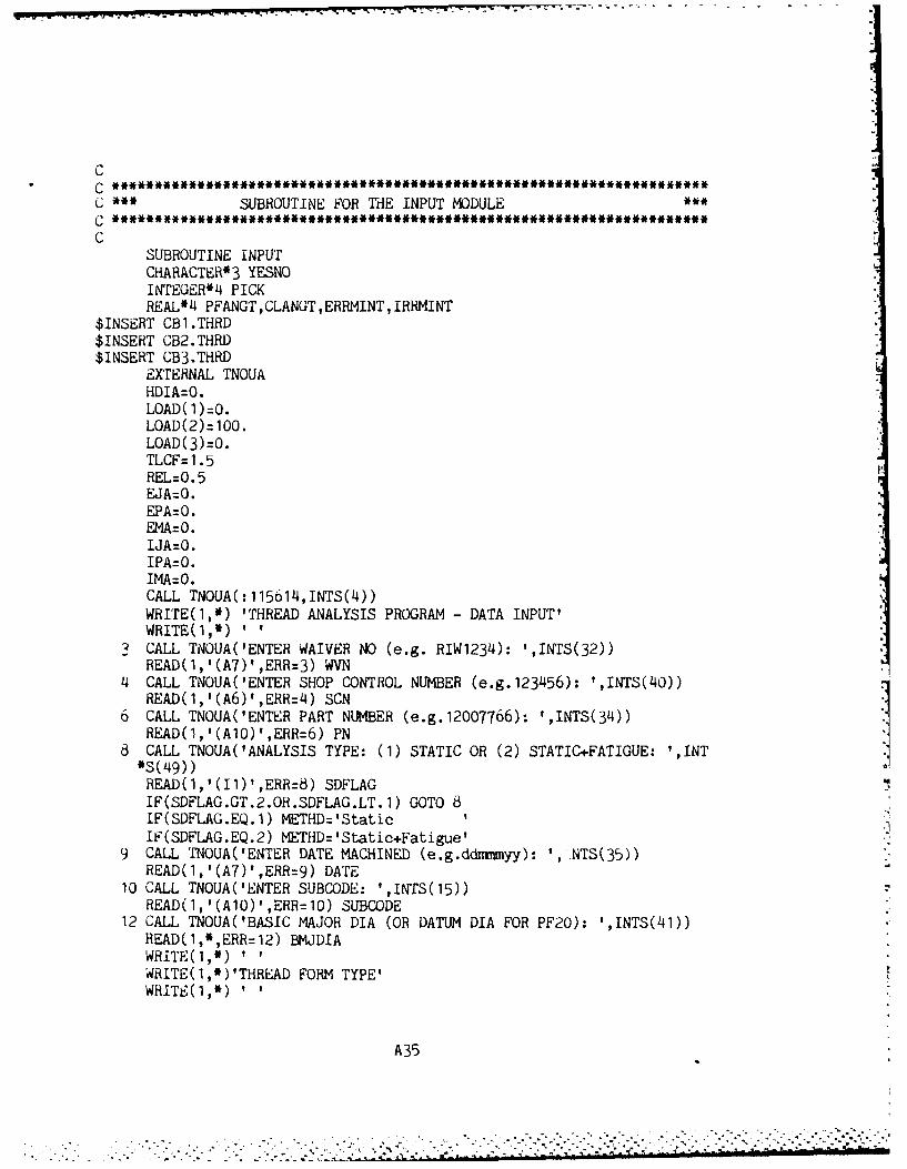
r- r r rJ - -~-- - ' - ' ~, -y-*.
C
C ***SUBROUTINE FOR THE INPUT MODULE
SUBROUTINE INPUTCHARACTER*3 YESNOINTEGER*4 PICKREAL4 PFANGr,CLANGT,ERRMINT, IRHMINT
$INSERT CB1.THRD$INSERT CB2.THRD$INSERT CB3.THRD
EXTERNAL TNOUAHDIA=O.LOAD (1)=:0LOAD (2) =100.LOAD (3) :0.ThCF= 1.5REL=0.5EJA=O.EPA: 0.EMA=O.
IPA=O.IMA=O.CALL TNOUA(:1150"14,INTS(4))WRITE(1,*) 'THREAD ANALYSIS PROGRAM -DATA INPUT'WRITE(1,*)1
3 CALL TNOUA('ENTER WAIVER NO (e.g. RIW1234): 1,INTS(32))READ(1,'(A7)',ERR=3) WVN
4~ CALL TNOUA('ENTER SHOP CONTROL NUMBER (e.g.123'456): ',INTS(40))READ(1,'(A,6)',ERR=4) SCN
6 CALL TNOUA(ENTER PART NUMBER (e.g.12007766): ',INTS(34))READ(1,'(Al0)',ERR=6) PN
6 CALL TNOUA('ANALYSIS TYPE: (1) STATIC OR (2) STATIC+FATIGUE: ',INT*S(k49))
READ(1,'I(11)I,ERR=8) SDFLAGIF(SDFLAG.GT.2.OR.SDFLAG.LT. 1) GOTO 8IF(SDFLAG.EQ.1) METHD='StaticIF(sDFLAG.EQ.2) METHD: 'Static+Fatigue'
9 CALL TNOUA('ENTER DATE MACHINED (e.g.ddrrmyy): ',.NTS(35))
READ( 1, '(A7)' ,ERR=9) DATE10 CALL TNOUA('ENTER SUBCODE: ',INTS(15))
READ(1,'(AlO)',ERR=10) SUBCODE12 CALL TNOUA(BASIC MAJOR DIA (OR DATUM DIA FOR PF2O): ',INTS(141))
READ(1,*,ERR:12) BMJDIAWRITE(1,*)'WRITE(1,*)'THREAD FORM TYPE'
A35
WRITEQ(1,*) 'V-THREAD............... 1'WRITE(1,*) 'ACME .................. 2'WRITE(1,*) 'STUB ACME ..............3''RITE(1,*) 'BUTTRESS ...............4'WRITE(1,*) 'PF20 .................. 5'
20 CALL TNOUA(ENTER TYPE: ',INTS(12))READ(l, '(Il)' ,ERR=20) SERIESIF(SERIES.LT.1.OR.SERIES.GT.5) GOTO 20 SIF(SERIES.NE.5) THEN
14 CALL TNOUA('THREADS PER INCH: ',INTS(18))READ(1,*,ERR=14) NENDIF
IF(SEHIES.EQ.1) THENWRITE(l,*) I ' I'WRITE(1,*) 'UN ...............1'WRITE(1,*) 'UNC.............. 2'WiiITE(1,*) 'UNE.............. 3tWHITE(1,*) 'UNEF............. 4'
22 CAL' TiNOUA('ENTER: ',INTS(7))READ(1,'(r1)',ERR=22) PICKIF(PICK.LT.1.UR.PICK.GT.4) GOTO 22!F(PICK.EQ.1) SERSTR=9UN1iF(PICK.EQ.2) SERSTR='UNC'IF(PICK.EQ.3) SERSTR='UNF'IF(PICK.EQ.4) SERSTR='UNEF'CALL TCLASSCALL H28VEEEND IF
!F(SERIES.EQ.2) THEN3i HSTR= 'ACME','ALL FCLAS
-NDI FIF i UV EQ -3) THEN
3Et~R TR: 'STUB3 ACME'C'ALL TCLASSCALL H~dSTBENDI F
I F(SE R 1ES .EQ. 4) THEN,-ERSTHz 'BUT'17CALL TCLASSC,,ALL d2dHIJTENDIF
CALL Fr)()
WMTH1v(A~,H~.)?, PRESSURE FACE (PF ANGLE): 'PFANG
A 36
WRITE(l,'(A22,F5.2)') 'CLEARANCE (CL ANGLE): ',CLANG25 CALL TNOUA('STANDARD PF & CL ANGLES?: ',INTS(26))
STD(1)WST , :) =FPEAu(1,'(A3)',ERR=25) YESNOIF(YESNO(1:1).EQ.'N') THEN
20 CALL TNOUA('ENTER PF ANGLE: ',INTS(16))READ( 1,*,ERR=26) PFANGTIF (PFANGT .NE. PEANG) THENSTD(1)='non-std'PFANG=PFANGTENDIF
28 CALL TNOUA('ENTER CL ANGLE: ',INTS(16))READ( 1,*,ERR=28) CLANGTIF(CLANGT.NE.CLANG) THENSTD(2)= 'non-std'CLANG=CLANGTENDIF
CALL iRECALCENDIF
WRITE(1,*)tWRITE(1,'(A22,F5.4)') 'EXT THRD ROOT RADIUS: ',ERRWRITE(1,'(A22,F.4)') 'INT THRD ROOT RADIUS: ',IRR
30 CALL TNOUA('STANDARD THREAD ROOT RADII?: ',INTS(29))STD(3)=STD(')=READ(1,'(A3)',EHRR3O) YESNOIF(YESNO(1:1).EQ.'N') THEN
32 CALL TNOUA('ENTER EXT THRD ROOT RADIUS: ',INTS(28))READ(1,'(F5.4)',ERR=32) ERRMINTIF(ERRMINT.NE.ERR) THENSTD(3)='non-std'ERR =ERRMI NTEND IF
314 CALL TNOUA('ENTER TNT THRD ROOT RADIUS: ',INTS(28))READ(1,l(F5.4)',ERR=34) IRRMINTIF(IRRMINT.NE.IRR) THENSTD(4)='non-std'I RR= IRRMINTENDIF
CALL RECALCENDIF
40 CALL TNOUA( 'HOLLOW DIA(in): ',INTrs(16))READUI,*,ERR=40) HDIAIF(HDIA.GE.BMJDIA) THENWRITE(1,*) 'HOLLOW DIA MUST BE LESS THAN EXT MEMER DIA.'GO'TO 40ENDIF
~42 CALL TNOUA('EQUIV O.D.(in): ',INTS(16))HEAI)(l,*,ERH=L42) ODIA
A37
.Li>BMDIA) HEN.WtITE(i,*) 'EQUIV OD MUST BE GREATER THEN INT THRD DIA.'
(:CAL TNOJA('THRD ENGAGEMENT LENGTH: ',INTS(24))RCA'(1 ,,Ep~44)LE
* o CAL I1LN0YA('THHD SEGMENT (FRACTION OF FULL): ',INTS(33))RF.AD( I ,*RR7-46) SECTOR
IF(EC7OR.LI .29)THENWRIT(1,*) 'CURRENT LOWER SEGMENT LIMIT IS .25'GOTO 165
T DFW4. CALL TNOUA('OAD FACTOR(1.5 normal): ',INTS(25))
READ( 1,*,ERHztPJ) TLCF)o CALL FNOtJA('ULTIMATE STRENGTH (EXT MEMBER) KSI: ',INTS(36))
HEAD1( 1,*,ERR=50) ETS- A-LL fNOUA('YIELD STRENGTH (EXT MEMBER) KSI: ',INTS(34))
iHEAT)(l1,*,EHR=52) EYSSCALL FNUUA('ULTIMATE STRENGTrH (INT MEMBER) 1(31: ',INTS(36))READ( 1,*,ERR=54) ITS
* ALL, T,' 10A('YIELD STRENGTH (INT MEMBER) KSI: ',INTS(31))-EAD~ 1,ERH 7 b) I YSY L,= A;,lN1 IEYS, I YS)WHITE(1.*) YSFS=AMIN1 (ETS, ITS)
WRIrE(1,)'* SURFACE FINISH FOR EXTERNAL MEMBER *
WH I 11( 1 *~p:y:(1 ,) MIRROR POLISHED ........ 14Kh(1,) FINE1 GROUND............2'~KK 1..)MACHINED...............3'
ec"lrb 1 'HOKT ROLLED.............4''.' - FORGED..............5'
AK:YKA2CNTER: ',INTS(7)),(i1)' ,ERR=58) ESURE
itF(LStRFJT..OR.ESURF.GT.5) GOTO 58S['2'ffF, W.EQ 1) ESURFSz 'MIRROR POLISHED'
;F~ A~F ~J&)ESURFS='FINE GROUND'ES U RFS ='MA CIINED'
* .. fijj'7;='HOT ROL[FL
i W TI~' I sf A TERNAL 1,T-MBER
1:11~ P, f OI F I 1
........ '
READ(1,'(I1)',ERR=60) ISURFIF(ISURF.LT.1.OR.ISURF.GT.5) GOTO 60.rF( ISURF .EQ. 1) IESURFS= 'MIRROR POLISHED'IF(ISURF.EQ.2) ISURFS= 'FINE GROUND'IF(ISURF.EQ. 3) ISURFS= 'MACHINED'IF(ISURF.EQ.4) ISURFS='HOT ROLLED'IF(ISURF.EQ.5) ISURFS='AS FORGED'WRITE(1,*) '*** EXTERNAL THREAD **'
62 CALL TNOUA('MAJOR DIA DEVIATION(in): ',INTS(25))READ(1,'(F7.14)',ERR=62) EJAWHITE(1,*) '** EXTERNAL THREAD '
6~4 CALL TNOUA(PITCH DIA DEVIATION(in): ',INTS(25))READ(1,'(F7.4)',ERR=64) EPAWHITE(1,*) '** EXTERNAL THREAD ~~
66 CALL TNOUA(MINOR DIA DEVIATION(in): ',INTS(25))READ(1,'(F7.14)',ERR=66) EMAWRITE(1,*) '*** INTERNAL THREAD *~
68 CALL TNOUA('MAJOR DIA DEVIATION(in): ',INTS(25))READ(1,'(F7.14)',ERR=68) IJAWRITE(1,*) '**' INTERNAL THREAD 3
70 CALL TNOUA('PITCH DIA DEVIATION(in): ',INTS(25))READ(1,'(F7.14)',ERR=70) IPAWRITE(1,*) "'* INTERNAL THREAD ~
72 CALL TNOUA(MINOR DIA DEVIATION(in): ',INTS(25))READ(1,'(F7.L4)',ERR=72) IMACALL INTCHKjCALL SURFARCALL BKLASHCALL PC VARCALL PRELOD
714 CALL TNOUA(ENTER MAX APPLIED AXIAL LOAD(kip): ',INTS(35))READ(1,*,ERR=74) LOAD(2)
76 CALL TNOUA('ENTER MIN APPLIED AXIAL LOAD(kip): ',INTS(35))
READ(1,',ERR=76) LOAD(3)IF(HDIA.EQ.0.) GOTO 82 7
78 CALL TNOUA(ENTER INTERNAL PRESSURE(PSI): ',INTS(30))READ(1,*,ERR=78) PRES(1
82 CALL TNOUA(ENTER TEMPERATURE(deg F): ',INTS(26))READ(1,l(1L4)',ERR=82) TEMPWRITE(l,'WHITE(I,*) "FATIGUE DATA RELIABILITY FACTOR ~WRITE(1,*)WRITE(1,*) '.5 (mean)............. 1'WRITE(1,*) '.9 ................ 2'WHITE(1,*) '.95 ................WRITE(1,*) '.99 ................. 1'
d4 CALL TNOUA( ENTER: t'INTS(8))
IF(IPICK.LT.1.OR.IPICK.GT.4) GOTO 8'4IF(IPICK.EQ.1) REL=.5
A39
IF(IPICK.EQ.2) REL=.9IF(IPICK.EQ.3) REL=.95iIF(IPICK.EQ.4) REL=.99CALL TNOUA(:115614,iNTS(4))
100 RETURNEND
A40
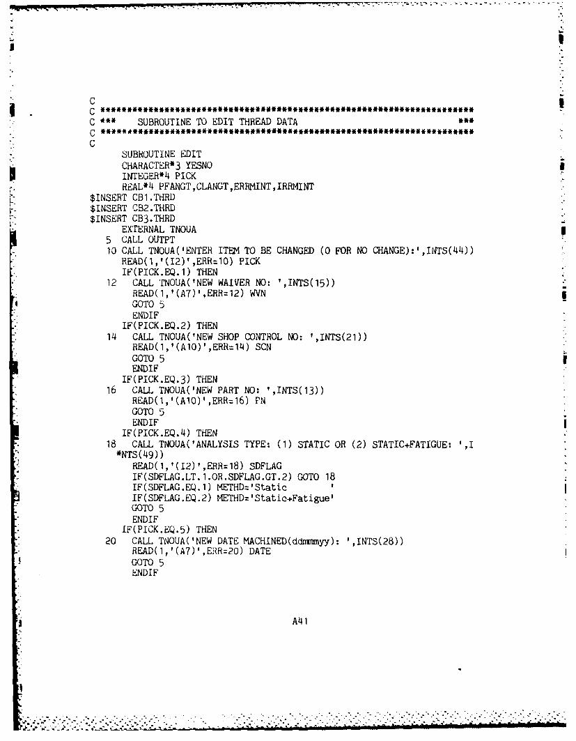
CC SUBROUTINE TO EDIT THREAD DATAC *************M*******~*~******,*M**C
SUBROUTINE EDITCHARACTER*3 YESNOINTEGER*4 PICK
$IN EACB1PTHRD ,CLANGT ,ERRNINT ,IRRMINT$INSERT CB2.THRD$INSERT CB3.THRD
EXTERNAL TNOUA5 CALL OUTPT10 CALL TNOUA('ENTER ITEM TO BE CHANGED (0 FOR NO CHANGE):',INTS(44))
READ(1,'(12)',ERR=10) PICKIF(PICK.EQ.1) THEN
12 CALL TNOUA('NEW WAIVER NO: ',INTS(15))RE-AD(l,'(A7)',ERR=12) WVNGOTO 5ENDIF
IF(PICK.EQ.2) THEN14 CALL TNOUA(tNEW SHOP CONTROL NO: ',INTS(21))
READ(l,'(AlQ)',ERR=l2 4) SCNGOTO 5ENDIF
IF(PICK.EQ.3) THEN16 CALL TNOUA('NEW PART NO: ',INTS(13))
GOTO 5ENDIF
IF(PICK.EQ.14) THEN18 CALL TNOUA(ANALYSIS TYPE: (1) STATIC OR (2) STATIC.FATIGUE: ',I*NTS(49))
READ(l,'(12)',ERR=18) SDFLAGIF(SDFLAG.LT.1.OR.SDFLAG.GT.2) GOTO 18IF(SDFLAG.EQ.1) METHDz'StaticIIIF(SDFLAG.EQ.2) METHD='Statio+Fatigue'GOTO 5END IF
IF(PICK.EQ.5) THEN20 CALL TNOUA('NEW DATE MACHINED(ddmyy): 'INTS(28))
READ(l,'(A7)',ERR=20) DATEGOTO 5ENDIF
A141
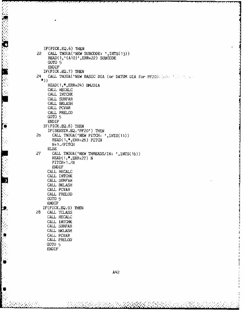
IF(PICK.EQ.6) THEN22 CALL TNOUA(NEW SUBCODE: ',INTS(13))
READ(l,'(A1O)',ERR=22) SUBOODEGOTO 5ENDIF
IF(PICK.EQ.7) THEN214 CALL TNOUA('NEW BASIC DIA (or DATUM DIA for PF20) Iv,):
RiEAD(1,*,ERR=24) BMJDIACALL kIECALC
- .CALL INTCHKCALL SURFARCALL BKLASHCALL PC VARCALL PRELODGOTOSENDIF
* IF(PICK.EQ.8) THENIF(SEHSTR.EQ. 'PF2O') THEN
2b CALL TNOUA('NEW PITCH: ',INTS(11))READ(1,*,ERR=26) PITCHN=1./PITCH
ELSE27 CALL TNOUA('NEW THREADS/IN: ',INTS(16))
READ(1,*,ERR=27) NPITCH=1 ./NE14DIF
CALL RECALCCALL INTCHKCALL SURFARCALL BKLASHCALL PC VARCALL PRELODGOTO 5ENDIF
IF(PICK.EQ.9) THEN28 CALL TCLASS
CALL RECALCCALL INTCHKCALL SURFARCALL BKLASH
* CALL PC VARCALL PRELODGOTO 5
* ENDIF
A4I2
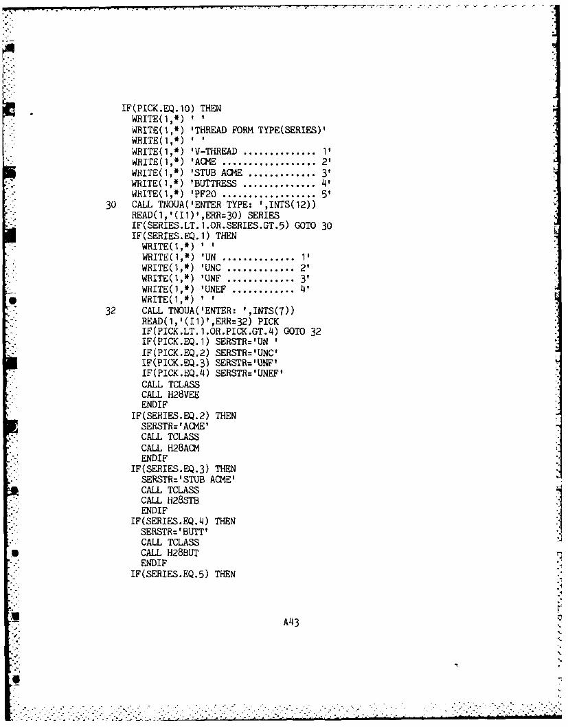
PTr I. ; Ir~ I-- 1. -T
IF(PICK.EQ.10) THENWRITE(1,*)WRITE(1,*) 'THREAD FORM TYPE(SERIES)'WRITE(1,*)'WRITE(1,*) 'V-THREAD .............. 11WJRITE(1,*) 'ACM4E.................. 2'WRITE(1,*) 'STUB AC1E ..............3'WHiITE(1,*) 'BUTTRESS .............. 4'WHITE(1,*) 'PF2O .................. 5
30 CALL TNOUA('ENTER TYPE: ',INTS(12))READ(1,'(I1)',ERR=3O) SERIESIF(SERIES.LT. 1.OR.SERIES.GT.5) GOTO 30IF(SERIES.EQ.1) THENWRITE(1,*)WRITE(1,*) 'UN .............. 11WRITE(1,*) 'UNG ............. 2'WRITE(1,*) 'UNF .............. 3'WRITE(1,*) 'UNEF .............L4'
* WRITE(1,*)32 CALL TNOUA('ENTER: ',INTS(7))
READ(l,'(Il)',ERR=32) PICKIF(PICK.LT.1.OR.PICK.GT.4) GOTO 32IF(PICK.EQ.1) SERSTR='UNIIF(PICK.EQ.2) SERSTR='UNC'IF(PICK.EQ.3) SERSTR='UNtF'IF(PICK.EQ.4) SERSTR='UNEF'CALL TCLASS,CALL H28VEEENDIF
IF(SERIES.EQ.2) THENSERSTR= ACIE'CALL TCLASS,CALL H28ACMENDIF
IF(SERIES.EQ.3) THENSERSTR='STUB ACME'CALL TCLASS,CALL H28STBEND IF
IF(SERIES.EQ.4) THENSERSTR=' BUTT'CALL TCLASS
* CALL H28BUTENDIF
IF(SERIES.EQ.5) THEN
A43.
SERSTR='PF2OCLASS=' '
CALL TCLASSCALL PF20ENDIF
314 CALL TNOUA('STANDARD PF & CL ANGLES?: ',INTS(2)STD(1):STD(2WzREAD( 1, '(A3)' ,ERR=34) YESNOIF(YESNC(1:1).EQ.'N') THEN
36 CALL TNOUA('ENTER PF ANGLE: ',INTS(16))READ(1 ,*,ERR=36) PFANGTIF(PFANGT.NE.PFANG) THEN
STD(1 )='non-std'PFANG=PFANGTENDIF
38 CALL TNOUA('ENTER CL ANGLE: ',INTS(16))READ(1,*,ERR=38) CLANGTIF(CLANGT.NE.CLANG) THEN
* STD(2)='non-std'* CLANG=CLANGT
ENDIFENDIF
WRITE(1,*)410 CALL TNOUA('STANDARD THREAD ROOT RADII?: ',INTS(29))
STD(3)=STDQ4)zREAD(1,'(A3)',ERR=30) YESNOIF(YESNO(1:1).EQ.'N') THEN
42 CALL TNOUA('ENTER EXT THRD ROOT RADIUS: ',INTS(28))RE.AD(1,'(F5.'4)',ERBR112) ERRMINTIF(ERRMINT.NE.ERR) THENSTD(3)='non-std'ERR=ERRMINTENDIF
414 CALL TNOUA('ENTER INT THRD ROOT RADIUS: ',INTS(28))READ(1,'(F5.4),ER144) IRRMINTIF(IRRMINT.NE.IRR) THEN
STD('4)='Inon-std'IRR=IHRMINT
* ENDIFEND IF
CALL RECALCCALL INTCHK
A4
. . . . .A.. .
CALL SURFARCALL BKLASHCALL PCVARCALL PRELODGOTO 5ENDIF
IF(PICK.EQ.11) THEN46 CALL TNOUA('NEW HOLLOW DIA(in): ',INTS(20))
READ(1,*,ERR=46) HDIAIF(HDIA.GE.BMJDIA) THENWRITE(1,*) 'HOLLOW DIA MUST BE LESS THAN EXT MEMBER DIA.'GOTO 46ENDIF
GOTO 5ENDIF
IF(PICK.EQ. 12) THEN48 CALL TNOUA('NEW EQUIV O.D.(in): ',INTS(20))
READ(1,*,ERR=48) ODIAIF(ODIA.LE.BMJDIA) THENWRITE(1,*) 'EQUIV OD MUST BE GREATER THAN INT THRD DIA.'GOTO 48ENDIF
GOTO 5ENDIF
IF(PICK.EQ.13) THEN50 CALL TNOUA('NEW ENGAGEMENT LENGTH(in): ',INTS(27))
READ(1,*,ERR=5O) LEGOTO 5ENDIF
IF(PICK.EQ.14) THEN52 CALL TNOUA('NEW THRD SEGMENT (FRACTION OF FULL): ',INTS(36))
READ(1,*,ERR:52) SECTORIF(SECTOR.LT. .249) THENWRITE(1,*) 'CURRENT LOWER LIMIT IS .25'GOTO 52ENDIF
IF(SECTOR.GT.1.) GOTO 52GOTO 5ENDIF
IF(PICK.EQ. 15) THEN54 CALL TNOUA('NEW LOAD FACTOR(1.5 normal): ',INTS(29))
READ(1,',ERR=54) TLCFGOTO 5ENDIF
IF(PICK.EQ.16) THEN
A45
56 CALL TNOUA(NEW T.S. EXT MEMBER(ksi): ',INTS(26))READ(1,*,ERR=56) ETSTS=AMIN1 (ETS,ITS)GOTO 5END IF
IF(PICK.EQ.17) THEN5,8 CALL TNOUA('wEW T.S. INT MEMBEH(ksi): ',INTS(26))
READ(1,*,ERR=58) ITSTS=AMIN1 (ETS, ITS)GOTO 5ENDIF
IF(PICK.EQ. 18) THEN60 CALL TNOUA(NEW Y.S. EXT MEMBER(ksi): ',INTS(26))
READ(1,*,ERR=60) EYSYS=AMIN1 (EYS,IYs)GOTO 5END IF
IF(PICK.EQ.19) THEN62 CALL 'NOUA(NEW Y.S. INT MEMBER(ksi): ',INTS(26))
READ(1,*,ERR=62) IYSYS=AiMIN1 (EYS, TYS)GOTO 5ENDIF
IF(PICK.EQ.20) THENWRITE1,)WRITE(1,*) "SURFACE FINISH FOR EXTERNAL MEMBER ~WRITE(1,')WRITE(1,*) 'MIRROR POLISHED ....... 1'WRITE(1,*) 'FINE GROUND ...........2'WHITE(1,*) 'MACHINED ..............3'WHITE(1,*) 'HOT ROLLED ............L4'WRilTE(1,*) 'AS FORGED .............5'
oL4 CALL TNOUA('ENTER: ',INTS(7))READ(1,'(Il)',ERR64) ESURFIF(ESURF.LT.1.OR.ESURF.GT.5) GOTO 6~4
* IF(ESURF.EQ. 1) ESURFS='MIRROR POLISHED'IF(ESURF.EQ.2) ESURFS='FINE GROUND'IF(ESURF.EQ. 3) ESURFS= 'MACHINED'IF(ESURF.EQ.4) ESURFS='HOT ROLLED'IF(ESURF.EQ.5) ESURFS='AS FORGED'GOTO 5
* ENDIFIF(PICK.FQ.21) THEN
* ~Hi~(1,; '~SURFACE FINISH FOR INTERNAL MEMBER "
A'46
:7I
WRITE(1,*)WRITE(1,*) 'MIRROR POLISHED ....... 1'WRITE(1,*) 'FINE GROUND ......... 2WRITE(1,*) 'MACHINED .............. 3'WRITE(1,*) 'HOT ROLLED ...........WRITE(1,*) 'AS FORGED ............. 5'
K 66 CALL TNOUA(ENTER: 'INTS(7))READ(1,'l(I1)',ERR=66) ISURFIF(ISURF.LT.1.OR.ISURF.GT.5) GOTO 66IF( ISURF .EQ. 1) ISURFS= 'MIRROR POLISHED'IF(ISURF.EQ.2) ISURFS='FINE GROUND'IF(ISURF.EQ.3) ISURFS: 'MACHINED'IF(ISURF .EQ. 4) ISURFS= 'HOT ROLLED'IF(ISURF.EQ.5) ISURFS='AS FORGED'GOTO 5ENDIF
IF(PICK.EQ.22) THEN'a 68 WlHITE(1,*) "'** EXTERNAL THREAD **68 CALL TNOUA('NEW MAJOR DIA(in) DEVIATION: ',INTS(29))
* READ(1,'(F7.4)',ERR=68) EJACALL INTCHKCALL SUHFARCALL PCVARGOTO 5ENDIF
IF(PICK.EQ.23) THENWRITE(1,*) '** EXTERNAL THREAD **
70 CALL TNOUA('NEW PITCH DIA(in) DEVIATION: ',INTS(29))READ(1,'(F7.4)',ERR4O0) EPACALL INTCHKCALL SURFARCALL PC VARGOTO 5ENDIF
IF(PICK.EQ.24) THENWRITE(1,*) '** EXTERNAL THREAD "
72 CALL TNOUA('NEW MINOR DIA(in) DEVIATION: ',INTS(29))READ(1,'(F7.1I)',ERR=72) EMACALL INTCHKCALL SURFARCALL PCVARGOTO 5ENDIF
IF(PICK.EQ.25) THENWRITE(1,*) '~*INTERNAL THREAD ~
A47
74 CALL TNOUA('NEW MAJOR DIA(in) DEVIATION: ',INTS(29))READ(1,'(F7.'4)',ERR=74) IJAIF( IJA.LE.IJX.AND.IJA .GE.IJN) IJA=O.CALL INTCHKCALL SUREARI CALL PCVARGOTO 5ENDIF
IF(PICK.EQ.26) TH{ENWRITE(1,*) '** INTERNAL THREAD
76 CALL TNOUA('NEW PITCH DIA(in) DEVIATION: ',INTS(29))S READ(1,'(F7.4)',ERR=76) IPAIF(IPA.LE.IPX.ANP.IPA.GE.IPN) IPA=O.CALL INTCHKCALL SURFARCALL POVARGOTO 5
I ENDIFIF(PICK.EQ.27) THEN
* WtITE(1,*) '*** INTERNAL THREAD*78 CALL TNOUA('NEW MINOR DIA(in) DEVIATION: ',INTS(29))
READ(1,'(Fj.L4)',ERR=78) IMAIF(IMA.LE.IM4X.AND.IMA.GE.IMN) IMA=O.CALL INTCHKCALL SURFARCALL PCVARGOTO 5EINDIF
IF(PICK.EQ.28) THENCALL PRELODGUTO 5E 'DIF
IF(PICK.EQ.29) THEN80 CALL TNOUA('ENTER MAX APPLIED AXIAL LOAD(kip): ',INTS(35))
* READ(1,*,ER(=80) LOAD(2)62 CALL TNOLJA('ENTER MIN APPLIED AXIAL LOAD(kip): ',INTS(35))
READ(1,*,EHRR=2) LOAD(3)GOTO 5
FkP:K.EQ.30) THEN*IFr(iDIA.EQ.O.) THEN
viflrE(1,') 'EXT THRD MEMBER IS NOT HOLLOW
G-JTO 130
Z. ~ 64 CALL 'fi"JUA( 'ENTER INTERNAL PRESSURE(KSI): ',INTS(30))fiEAD)(1,*,ERR~dL4) PRES(1)
A48I
IF(PICK.EQ.31) THEN88 GALL TNOUA('ENTER TEMPERATURE(deg F): ',INTS(26))
READ(1,l(1~4)l,ERR=88) TEMPGOTO 5ENDIF
IF(PICK.EQ.32) THEN
WRITE(1,*) '~FATIGUE DATA RELIABILITY FACTOR *
WRITE(1,*)WRITE(1,') '.5 (mean)........... 1'WRITE(1,') '.9 ................. 2'WJRITE(1,*) '.95 ................ 3'WRITE(1,*) 1.99 ................ 4'
92 CALL TNOUA(' ENTER: ',iNTs(8))READ(1,'(Il)',ERR=92) IPICKIF(IPICK.LT.1.OR.IPICK.GT.4) GOTO 8~4IF(IPICK.EQ.1) REL=.5IF(IPICK.EQ.2) REL=.9IF(IPICK.EQ.3) REL=.95IF(IPICK.EQ.4) REL=.99GOTO 5ENDIF
100 CALL TNOUA(:115614,INTS(4))RETURNEND
A49
C
C *** SUBROUTINE TO GENERATE INTERMEDIATE OUTPUT FOR REVIEW & EDIT
C
SUBROUTINE OUTPT$INSERT CB1.THRD$INSERT CB2.THRD$INSERT CB3.THRD
REAL*4 EJTOL ,EPTOL,FE1TOL ,IJTOL ,IPTOL,IMTOLEXTERNAL TNOUACALL TNOUA(:115614,INTS(4))WRITE(1,*) I ** THREAD DATA *I
WRITE(1,*)')WRITE(1,1O) ' 1. WAIVER NOI~K,WVN,'2. SCN#:',SCN,'3. PART ND:',PN
10 FORMAT(A1J4,1X,A7,8X,A8,lX,A7,8X,Al1,lX,A8)WRITE(1,11) ' 4. METHOD:',METHD,'5. DATE MACH:',DATE,'6. SUBOODE:'
* ,SUBCODE11 FORMAT(A1 1, X,A14,14X,A13, 1X,A7,3X,A1 1, X,A1O)
IF(SERIES.EQ.5) THENWRITE(1,12) ' 7. DATUM DIA(in):',BMJDIA,'8. PITCH: ',PITCH
12 FORMAT(Al8,lX,F71.4,14X,A1O,lX,F7.4)ENDIFIF(SERIES.NE.5) THENWRITE(1,1'3) ' 7. BASIC DIA(in):',BMJDlA,'8. THREADS/IN:',N,'9. CLA
*SS:I ,CLASS13 FORMAT(A18,lX,F7.4,14X,A114,lX,F5.2,14X,A9,lX,A2)
END IFWRITE(1,)WRITE(1,14) '10. THREAD FORM:',SERSTR,'11. HOLLOW DIA(in):',HDIA
14 FORMAT(Al6,1X,A1O,17X,A19,lX,F6.3)WRITE(1,16) 'PF ANGLE(deg):',PFANG,STD(l),'12. EQUIV O..D.(in):',OD*IA
16 FORMAT(14X,A14,X,F5.2,lX,A8,11X,A19,lX,F6.3)WRITE(1,18) 'CL ANGLE(deg):',CLANG,STD(2),'13. ENGAGEM'ENT LENGTH(i*:',LE
18 FORMAT(14X,A14,lX,F5.2,lX,A8,l1XA26,lX,F5.2)WHITE(1,20) 'EXT ROOT RADIUS(in):',ERR,STD(3),'14. INTERRUPTED THR*1) FACTOR:' ,SECTOHi
20 FORMAT(14X,A20,lX,F5.4,lX,A9,14X,A28,lX,F5.3)WRIi'E(1,22) 'INT ROOT RADIUS(in):',IRR,STD(4),'15. LOAD FACTOR(1-I
*,1 .5nom):' ,TLCF22 FOHiMAT(4X,A20,lX,F5.4,lX,A9,4X,A28,lX,F4.2)
WHITE(1,*)IIWRiTE(1,24) '16. T.S. EXT MEMBER(ksi):',ETS,'17. T.S. INT MEMBER(
*ksi ):' ,ITS214 FORMAT(A25,lX,F6.2,5X,A25,lX,F6.2)
WRITE(1,24) '18. Y.S. EXT MEMBER(ksi):',EYS,'19. Y.S. INT MEMBER(*ksi):' ,IYSWRITE(1,26) '20. SURF EXT MEMER:',ESURFS,'21. SURF INT MEMBER:',I
A50
*SUHFS20 FO'RMAT(A2,lX,A15,lX,A2O,lX,A15)
WRITE(1,28) 'EXTERNAL THREAD','SPEC(in)','DEV(in)','VAR(%)'26 FOHMAT(3X,A15,11X,A'4,15X,A3,13X,A3)
EJTOL=FEJX-EJNEPTOL=EPX-EPNEt~TOL =EMX-EMNIJTOL=IJX-IJNIPTOL=IPX-IPNIMTOL= IMX- IMNWHIiTE0l,30) '22. MAJOR DIA(in):',E.JX,'-',E.JTOL,EJA,EJV
30 FORMAT(A7,9X,F7.4,A,F5.4,7X,F7.4,9X,F7.5)WRITE(1,30) '23. PITCH DIA(in):',EPX,'-',EPTOL,EPA,EPVWRITE(1,30) '24. MINOR DIA(in):',EMX,'-',EMTrOL,EMA,EMVWHITE(1,28) 'INTERNAL THREAD' ,'SPEC','DEV','VAR'wRiTrE(1,30) '25. MAJOR DIA(in):',IJN,'+',IJTOL,IJA,IJVWRITE(1,30) '26. PITCH DIA(in):',IPN,'+',IPTOL,IPA,IPVWRITE(1,30) '27. MINOR DIA(in):',IMN,'+',IMTOL,IMA,IMVWRi'TE(1, *) ItWRITE(1,32) '28. APPLIED PRELOAD(kip):',LOAD(1),'DECIMAL OF MAX AL*LOWABLE:' ,FPFRAC
32 FORMAT(A25,lX,F8.2,7X,A25,lX,F4.2)WRITE( 1,34) 'APPROX TIGHTENING TORQUE(ft-lb):' ,TORQ, 'FRICTION FACT0OR:' ,FF
34 FORMAT(4X,A32,1X,F8.2,9X,A16,lX,F4i.2)WRITE(1,36) '29. AXIAL LOAD(kip):',LOAD(2),'(max)',LOAD(3),'(min)I
36 FORMAT(A20,1X,F8.2,lX,A5,2X,F8.2,lX,A5)WRITE(1,38) '30. INTERNAL PRESSURE(ksi):',PRES(1)
38 FORMAT(A27,lX,F8.2)WRITE(1,40) '31. TEMPERATURE(deg F):',TEMP,'32. FATIGUE DATA REL:'
* ,REL
40 FORMAT(A23,lX,I4l,114X,A21,lX,F5.4)
IF(SARV.GT.30.) THENWRITE(1,*) 'NOTE: THREAD SURFACE CONTACT AREA HAS BEEN REDUCED
*MODRE THANWRITE(1,*) '30% OF MIN SPEC CONDITION. SPECIAL CONSIDERATION MA
*Y BE REQUIRED.'ENDIF
IF(SERIES.EQ.2.OR.SERIES.EQ.3) THENWRITE(1,*) 'NOTE: THREAD BACKLASH CONDITIONS ARE AS FOLLOWS.'WRITE(1,50) 'BI. TO SPEC: ',BLS,' BL TO DEV: ',BLD
50 FORMAT(Al2,F5.4,1OX,A12,F5.4)END IF
WHITE(1,*)RETURNEND
A5 1

C
C ' ~ SUBROUTINE TO CHECK FOR INTERFERENCESCC
SUBROUTINE INTCHKREAL*4 G1,G2CHARACTER*3 HETN
$INSERT CB1 .TiIHD$INSERT C32.7:3RD$INSERT CB3.Ti~HD
INTFLGz (IF(EJA.E--Q.O.) JlzEJX
IF(EJ.NE.O) SiEJAIF(IJA.EQ.O.) J;2rIJN
It(IA.NEJ.) 2zIJAIiIGl.U? '.62) THEN
dRITE(1*) ' '~INTERFERENCE CONDITION ~*WHIY( 1,) 1.'F( 1oo*(G1-s2)+.5)/1ooo, 'IN INTERFERENCE AT THREAD
*MAJOR DIAMETERS'
-INiELS: 1ENDI F
IF(EPA.EQ.U.) G1=EPXIF(EPA.NE.Q.) GizEPAIF(IPA.EQ.O.) G2zIPNIF(IPA.NE.O.) G2zIPAIF(G1.GT.G2) THENWRITE(1,*)II
WHIE(1*)I *** INTERFERENCE CONDITION "i
WRITE(,5)IT(1OOO*(G1-G2)+.5)/1OOO,?IN INTERFERENCE AT THREAD*PITCH DIAMETER.)'
IF(VA.L4O.) 1zEMXlF(UilA.UE.U.) Jiz=EMAIF(LAA.EQ.O.) G2zIMN
IF(MA.E.J) 2=IMA
AHIVK1,*) 'INTERFERENCE CONDITION **
r&1T5 1,5) IN(1000'(G1-02)+.5)/1000,'IN INTERFERENCE AT THREAD
CAL PRES RETURN DOIAOGAMMETERS'INT(44HrL( 1,*0) 'EE
30 FORMAT (Al-. P MV
ENDIFRETfURN
END A52
C
C * SUBROUTINE TO CALCULATE BACKLASH CONDITIONS
CC rhis calculation assumes perfect thread formulation as per theC H26 specifications.C
SUBROUTINE BKLASH$INSERT CB1.THRD$INSERT CB2.THRD$INSERT CB3.THRD
BLPFS=(IPX-EPN)*TAN(PFRAD) /*BACKLASH PRESSURE FACE SIDE: TO SPECBLCFS=(IPX-EPN)*TAN(CLRAD) /*BACKLASH CLEARANC FACE SIDE: TO SPECIF(IPA.EQ.O) THENQI=IPX
ELSEQ1=IPAENDIF
IF(EPA.EQ.O) THENQ2=EPN
ELSEQ2=EPNENDIF
BLPFD=(QI-Q2)*TAN(PFRAD) /*BACKLASH PRESSURE FACE SIDE: ACTUALBLCFD=(Q1-Q2)*TAN(CLRAD) /*BACKLASH CLEARANC FACE SIDE: ACTUALBLS=BLPFS+BLCFS /*BACKLASH TOTAL: TO SPECBLD=BLPFD+BLCFD /*BACKLASH TOTAL: ACTUALRETURNEND
AI
A53
C SUBROUTINE £0 CALCULATE VARIANCES FROM TO SPEC GEO 1
CSUBROUTINE PCVAR
$INSERT CB31.THFiD$INSERT *-i,).THRD$ INSERT CB3 .THRi)
CHARAC,'1ER*,) R3EJC* VARiAN,:E OF MAJOR DIA ON EXTERNAL THREAD ~I
1I'EJA.LF.EJN.AND.E.JA.NE.O.) EJV=EJA-EJNIF(EFjA.F.0..) EJV=O.IF'(EJA.LE.EJX.AND.EJA.GE.EJN) EJV=O.IF(EjA.GT.EJX) EJV=EJA-EJX
C VAPi7At:F PITCH DIA ON EXTERNAL THREAD'IF(FPA.l.E.;PN.AND.EPA'NE.D.) EPV=EPA-EPNIF.,LPA.Ea.,.O.) rPV=O.U%2APk~.E.EPX.AND.EPA.GE.EPN) EPV=O.IF EPA.0 T.EPX) EPV=EPA-EPX
C**VARIANC:E CF MINOR DIA ON EXTERNAL THREADiF'(EmA.LTr.hXN.AND.EM1A.NE.O.) EtIV=EMA-EMNIF'EMA.EQ.O.) EMVO0.Ii(EMA.LE.EMX.AND).EM-A.GE.EMN) EPV=O.IF (IYA .GT. EMX) t1MV=EMA-EMX
C VARiANCE oF MAJOR DIA ON INTERNAL THREAD ~IF(IA.L.IJ.AN.IJ.NEO.)IJV=IJA-IJN
iF(IJA.LE.IU'X.AND.IJA.GE.IJN) IJV=O.ilK IJA.GT. IJX) IJV=IJA-IJX
C VARiAi'#CE OF PITCH DIA ON INTERNAL THREADTIPA.1,E. i9N.AND. IPA.NE.0. ) IPV=IPA-IPX
lF(iPA.LE.IPX.AND.IPA.GE.IPN) IPV=O.IF(IPA.GT,.ipx) IPV=IPA-IPX
C VARIANCE OF MINOR DIA ON INTERNAL THREAD ~IF( IMA.LE.IMN.AND.IMA.NE.O.) IMV=IMA-IMN 7
IV(IMA.LQ.O.) IMVzO.IF(IMA.LE.IMX.AND.IMA.GE.IMN) IMV=O.ilF( IMA .0'--.IMX) IMV=IMA-IMXF(SiliA.3GT'.SARX) THEN
.i>ArV=,0)o.*(INT'l,((1000O.*(SARA-SARX)/SARX)+.5)/10QOO.)ENDIF
IF(SARA.:L . SARN) THENSARV=! 1O).*(INTL,(( 1OOO.*(SARA-SAN)/SAN)+.5)/1OOOO.)
U-'(;AH.IFARN.AN'D.SARA.LE.SARX) SARYZO.RETUH:4END
A54
CC*****************V0*****I***I**#****C SUBROUTINE TO PRESENT CLASS MENU AND SELECTIONC ********~*******I***.**i***********
CSUBROUTINE TCLASSINTEGER*4 PICK
$INSERT CB1.THRD$INSERT CB2.THRD$INSERT CB3.THRD
EXTERNAL TNOUAIF(SERIES.EQ.1) THEN /* V-THREAD SERIES
WRITE(1,*) UNIFIED NATIONAL THREAD CLASSES ~WRITE(1,*)WRITE(1,*) ' CLASS 1..................1'lWRITE(1,*) ' CLASS 2 .................. 2'WRITE( 1,*) CLASS 3 ............... 3'WRITE(1,*) 'CALL TNOUA('ENTER: ',INTS(7))
10 READ(1,'(Il)',ERl=10) PICKIF(PICK.EQ.1) CLASS='1IF(PICK.EQ.2) CLASS='2IF(PICK.EQ.3) CLASS='31ENDIF
IF(SERIES.EQ.2) THEN /* ACME SERIESWRITE(1,*) 'WRITE(1,*) ' ACME THREAD CLASSESWRITE(1,*)WRITE(1,*) '(1) CLASS 2G (14) CLASS 2C'WRITE(1,*) '(2) CLASS 3G (5) CLASS 3C'WRITE(1,') '(3) CLASS J4G (6) CLASS 4C'WRITE(1,*) ' (7) CLASS 5C'WRITE(1,*) ' (8) CLASS 6C'WRITE(1,*)
20 CALL TNOUA('ENTER: ',INTS(7))READ(l,'(Il)',ERR=20) PICK
*IF(PICK.EQ.1) CLASS=12G'IF(PICK.EQ.2) CLASS='3G'IF(PICK.EQ.3) CLASS='14G'IF(PICK.EQ.4) CLASS='2C'IF(PICK.EQ.5) CLASS='3CfIF(PICK.EQ.6) CLASS='14C'
*IF(PICK.EQ.7) CLASS='5C'IF(PICK.EQ.8) CLASS='6C'ENDIF
*IF(SERIES.EQ.3) THEN /* STUB ACME SERIESWRITE(1,*)WRITE(1,*) '" STUB ACME CLASSESWRITE(1,*)
A55
WRITE(1,*) 'CLASS 1 (Std Stub Acme Form).......1'WRITE(1,*) 'CLASS 2 (Modified Form 1 Stub) ... 2'WRITE(1,*) 'CLASS 3 (Modified Form 2 Stub) ... 3'WHITE( 1,*)
30 CALL TNOUA('ENTER: ',INTS(7))READ(1,'(Il)',ERR=30) PICKIF(PICK.EQ. 1) CLASS='1 I.IF(PICK.EQ.2) CLASS='2IIF(PICK.EQ.3) CLASS='3ENDIF
IF(SERIES.EQ.4) THEN /* BUTT~RESS SERIESWRITE(1,*)IIWRITE(1,*) STANDARD BUTTRESS CLASSESWkIITE(1,*)WRITE(1,*) ' CLASS 1................. 1'WRITE(1,*) ' CLASS 2 ................ 2'WRITE(1,*) CLASS 3 ............... 3'WRITE(1,*) '
~40 CALL TNOUA('ENTER: ',INTS(7))READ(1,'(I1)l,ERR=40) PICKIF(PICK.EQ.1) CLASS'1lIF(PICK.EQ.2) CLASS='2I
*IF(PICK.EQ.3) CLASS='3IF(PICK.LT.1.OR.PICK.3T.I) GOTO 40ENDIF
IF(SERIES.EQ.5) THEN I' PF20 SPECIAL THREADCLASS='-EN DIF
RETURNEND
A56
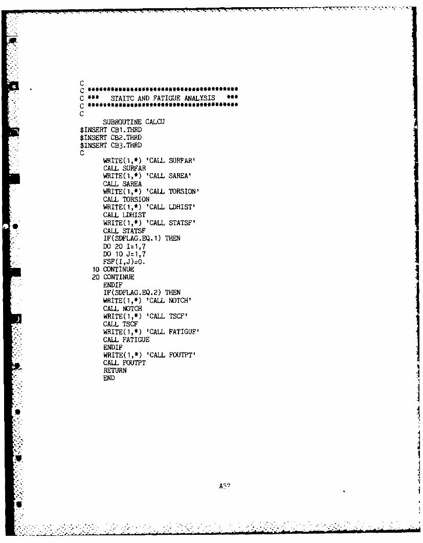
.74.
CC
C * STAITC AND FATIGUE ANALYSIS **o *****************************I**C
SUBROUTINE CALCU$INSERT CB1.THRD$INSERT CB2.THRD$INSERT CB3. THRDC
WRITE(1,*) 'CALL SURFAR'CALL SURFARWRITE(1,*) 'CALL SAREA'CALL SAREAWRITE(1,*) 'CALL TORSION'CALL TORSIONWRITE(1,*) 'CALL LDHIST'CALL LDHIST
* WRITE(1,*) 'CALL STATSF'CALL STATSFIF(SDFLAG.EQ.1) THENDO 20 I=1,7DO 10 J=1,7
" " 'FSF(I,J)zO.
10 CONTINUE20 CONTINUE
ENDIFIF(SDFLAG.EQ.2) THENWRITE(1,*) 'CALL NOTCH'CALL NOTCH
WRITE(1,*) 'CALL TSCF'CALL TSCFWRITE(1,*) 'CALL FATIGUF'CALL FATIGUEENDIF
WRITE(1,*) 'CALL FOUTPT'CALL FOUTPTRETURNEND
Af" 7.111
U.
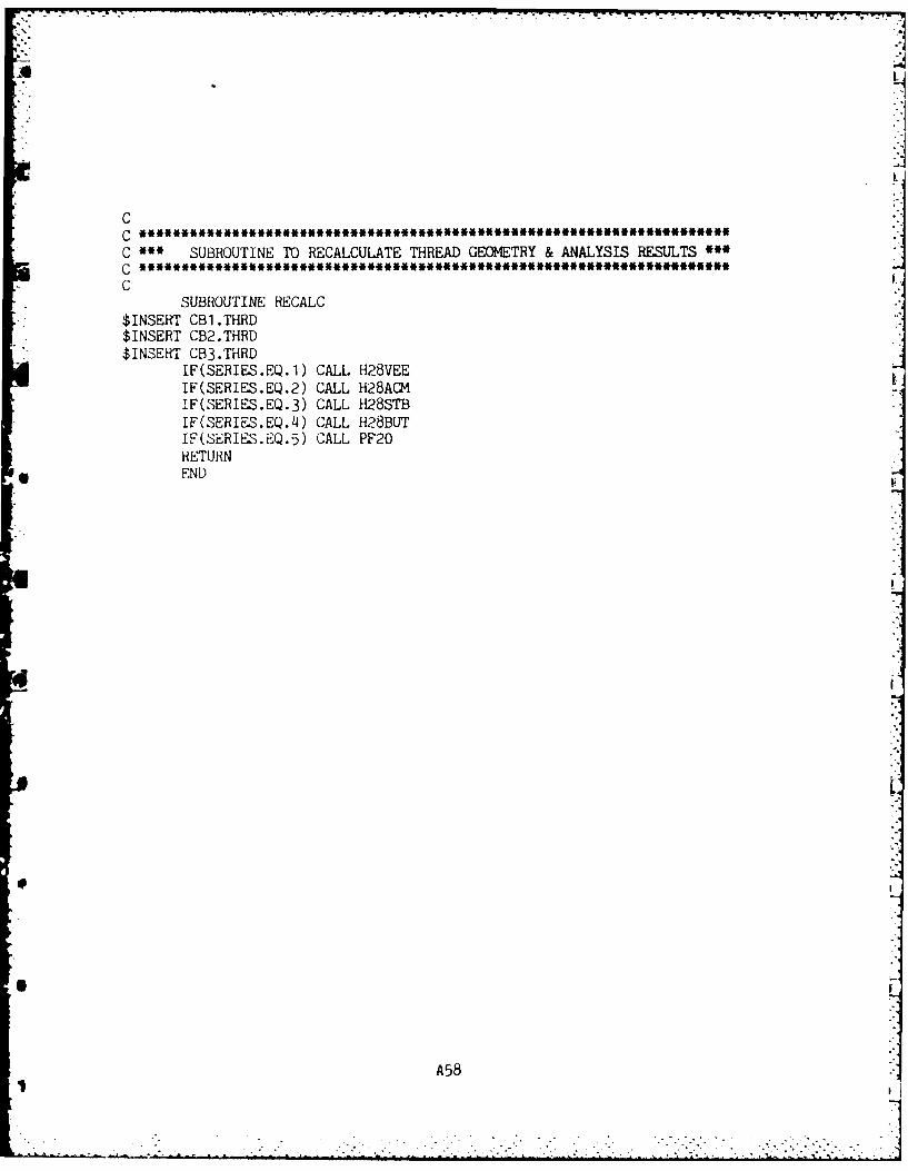
A
CCC ** SUBROUTINE TO RECALCULATE THREAD GEOMETRY & ANALYSIS RESULTS **
~~C *i***************.****.**********.******u******************C-- C
SUBROUTINE RECALC$INSERT CB1.THRD$INSERT CB2.THRD$INSERT CB3.THRD
IF(SERIES.EQ.1) CALL H28VEEIF(SERIES.EQ.2) CALL H28A(MIF(SERIES.EQ.3) CALL H28STBIF(SERIES.EQ.4) CALL H28BUTIF(SERIES.EQ.5) CALL PF20RETURN
*END
A58
-I "I- i --- i -i ,
.-°
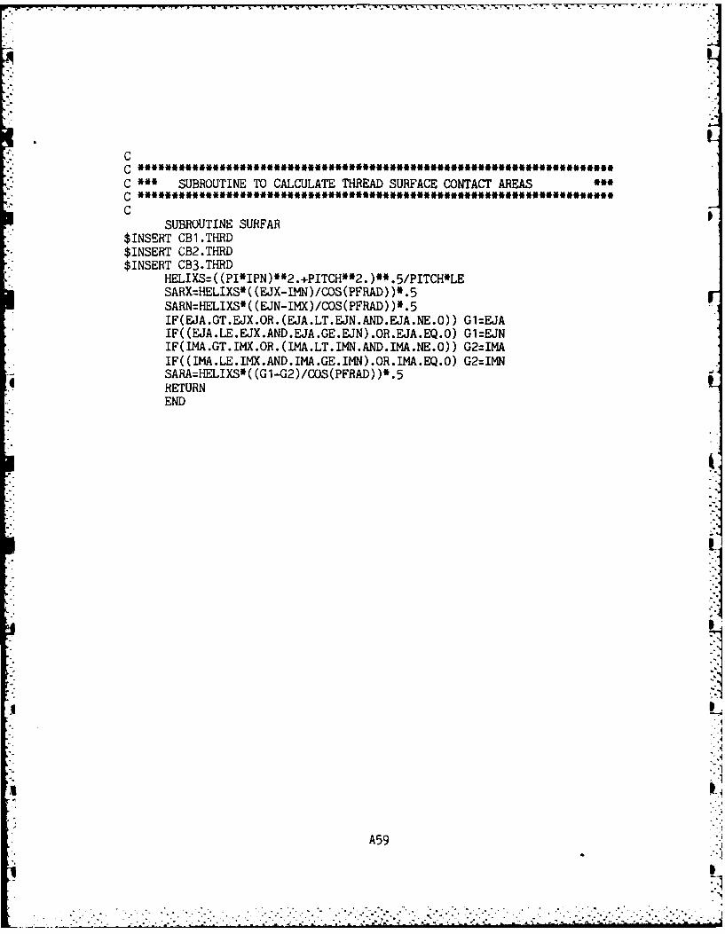
- r wn
C
C SUBROUTINE TO CALCULATE THREAD SURFACE CONTACT AREAS
CSUBROUTINE SURFAR
$INSERT CB1.THRD$INSERT CB2.THR.D$INSERT CB3.THRD
HELIXS=( (PI*IPN)**2.+PITCH**2. )**.5/PITCH*LESARX=HELIXS ( (EJX-IMN)/COS(PFRAD) )*.5SARN=HELIXS*( (EJN-IMX)/COS(PFRAD) )*.5IF(EJA.GT.EJX.OR.(EJA.LT.EJN.AND.EJA.NE.O)) Gl=EJAIF((EJA.LE.EJX.AND.EJA.GE.EJN).OR.EJA.EQ.O) Gl=EJNIF(IMA.GT.IMX.OR.(IMA.LT.IMN.AND.IMA.NE.O)) G2=IMAIF( (IMA.LE.IMX.AND.IMA.GE.IKN) .OR.IMA.EQ.O) G2=IMN
4 SARA=HELIXS*( (Gl-G2)/COS(PFRAD) )*.5RETURNEND
A59
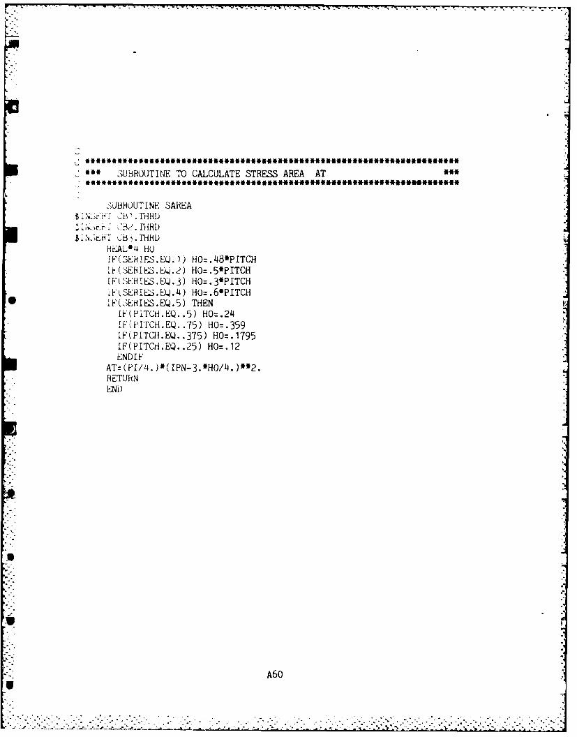
3 UBROUTINE TO CALCULATE STRESS AREA AT
3JBUUTNESAREA
. N''fCB 1 . FHRD
REAL*4 HO!F(SEkIES.EQ.1) HO=.J48*PITCHIF(3EHIES.EQ.2) HO=.5*PIETCH
IF(EHIS.E.3)HO=.3*PITCHiF SERIES.EQ.4 ) HO=.6'PITCH
* IFS~r(ES.E.5)THENIF(PITCH.EQ. .5) HO=.24lF(PI'rCH.EQ. .75) HO=.359IF(PITCH.EQ. .375) HO=.1795iF(PITCH.EQ..25) HO=.12ENDI F
RETURNEND)
A60
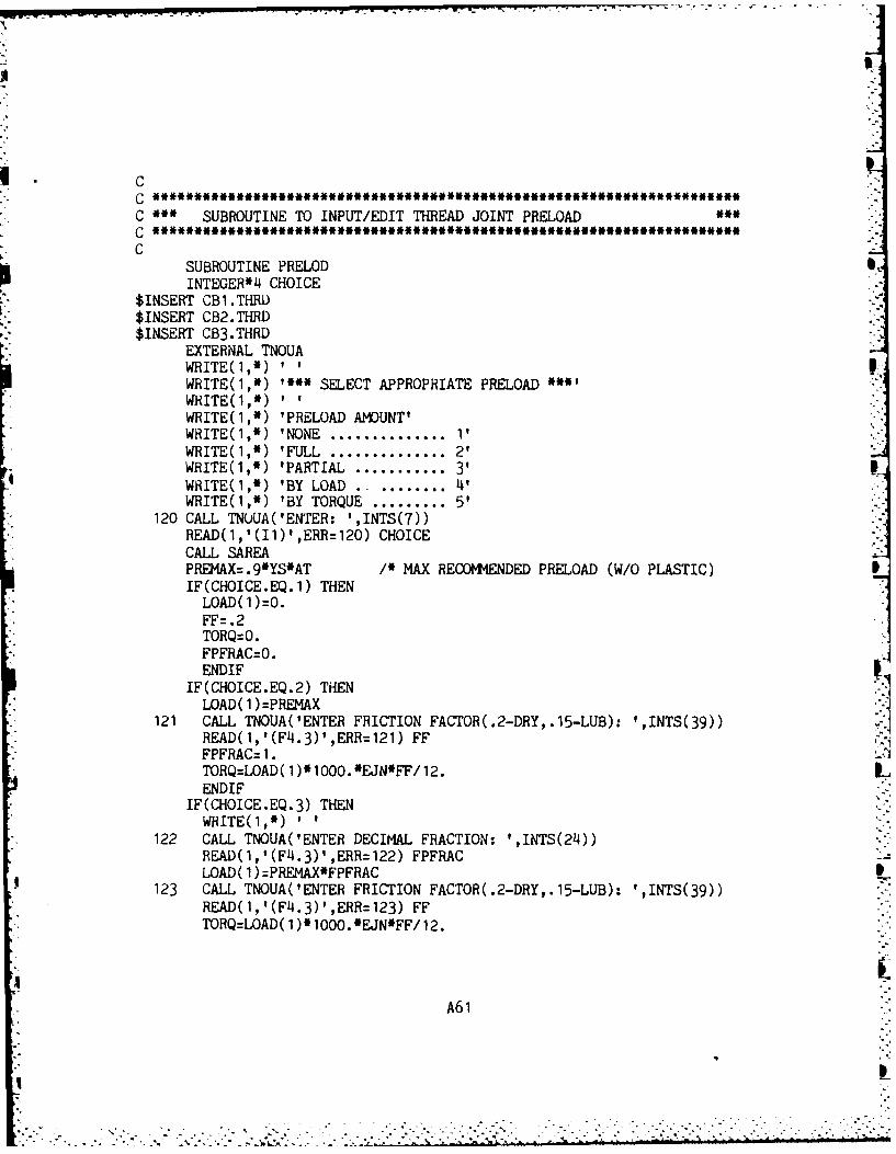
IC* C * SUBROUTINE TO INPUT/EDIT THREAD JOINT PRELOAD
CSUBROUTINE PRELOD SINTEGER*4 CHOICE
$INSERT CB1.THRi)$INSERT CB2.THRD$INSERT CB3.THRD
EXTERNAL TNOUAWRITE(1,')''WRITE(1,*) '~~SELECT APPROPRIATE PRELOAD ~WRITE(1,*)WRITE(1,*) 'PRELOAD AMOUNT'WHITE(l,*) 'NONE ...............1'WRITE(1,*) 'FULL ...............2'
WRITE(1,*) 'PARTIAL ............ 3'WHITE(1,*) 'BY LOAD ........ 4'WRITE(1, M) 'BY TORQUE .......... 5'
120 CALL TNUUA('ENTER: ',INTS(7))READ(,'(I1),ERR=120) CHOICECALL SAEAPREMAX . 9*YS*AT /* MAX RECOMMlENDED PRELOAD (W/O PLASTIC)IF(CHOICE.EQ.1) THENLOAD( 1 )O.FF=.2TORQ0O.FPFRAC=O.ENDIF
IF(CHOICE.EQ.2) THEN
LOAD( 1)=PREMAX121 CALL TNOUA(ENTER FRICTION FACTOR(.2-DRY, .15-LUB): ',INTS(39)) 1
READ(1,'(FL4.3)',ERR=121) FFFPFRACZ 1.TORQzLOAD( 1)*1000.*E.JN*FF/12.END IF
IF(CHOICE.EQ.3) THENWITE(1,*)
122 CALL TNOUA(ENTER DECIMAL FRACTION: ',INTS(24))READ(l,'(F4.3)' ,ERR=122) FPFRACLOAD( 1)=PREMAX*FPFRAC
123 CALL TNOUA( ENTER FRICTION FACTOR( .2-DRY,. 15-LUB): ',INTS(39))READ(l,'(F'4.3)',ERR=123) FFTORQ=LOAD( 1 )1000.'EJN*FF/12.
A6 1
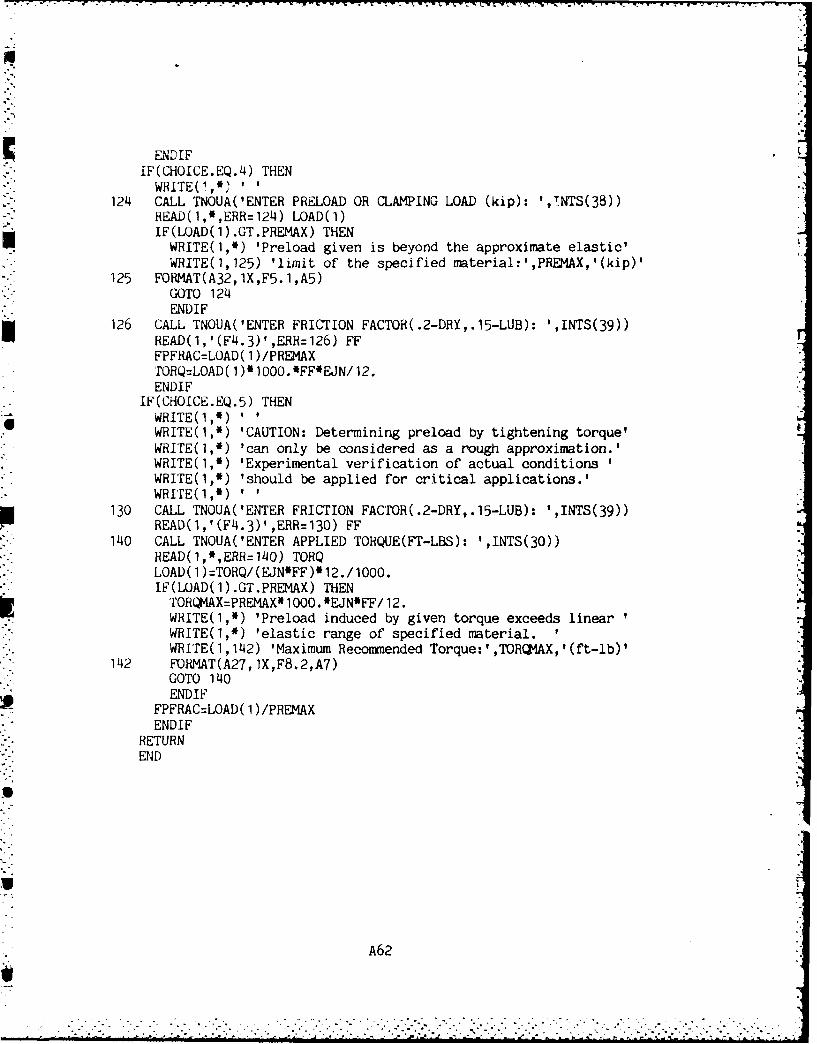
ENDIFIF(CHOICE.EQ.4) THENWRITE(',)..
124 CALL TNOUA(ENTER PRELOAD OR CLAMPING LOAD (kip): t,TNTS(38))READ(1,,ERR=124) LOAD(1)IF(LOAD(l).GT.PREMAX) THENWRITE(1,*) 'Preload given is beyond the approximate elastic'WRITE(1,125) 'limit of the specified material:',PREMAX,'(kip)'
125 FORMAT(A32,1X,F5.1,A5)GOTO 124ENDIF
126 CALL TNOUA('ENTER FRICTION FACTOR(.2-DRY,.15-LUB): ',INTS(39))READ(1,'(FL4.3),ERI=126) FE'FPFRAC=LOAD( 1)/PREMAXrOHQ=LOAD (1) *1000. 'FF*FEJN/ 12.ENDIF
IF(CHOICE.EQ.5) THEN
WRITE(1,*) 'CAUTION: Determining preload by tightening torque'WRITE(1,*) 'can only be considered as a rough approximation.'WRITE(1,*) 'Experimental verification of actual conditionsWRITE(1,*) 'should be applied for critical applications.'WRI'rE(1,*)
130 CALL TNOUA( 'ENTER FRICTION FACTOR( .2-DRY,. 15-LUB): fINTS(39))READ(1,'(FL4.3)1,ERR130) FF
140 CALL TNOUA('ENTER APPLIED TORQUE(FT-LBS): ',INTS(30))READ(19*,ERR=140) TORQLOAD( 1)=TORQ/(EJN*FF)*12./1OOO.IF(LOAD(l).GT.PREMAX) THENTORQMAX=PREMAX' 1000. *EJN*FF/ 12.WRITE(1,*) 'Preload induced by given torque exceeds linearWRITE(1,*) 'elastic range of specified material.WRITE(1,1142) 'Maximum Recommuended Torque:' ,TORQM.AX, '(ft-lb)'
142 FO1MT(A27,1X,F8.2,A7)GOTO 140ENDIF
FPFRAC=LOAD( 1)/PREMAXENDIF
RETURNEND
A62
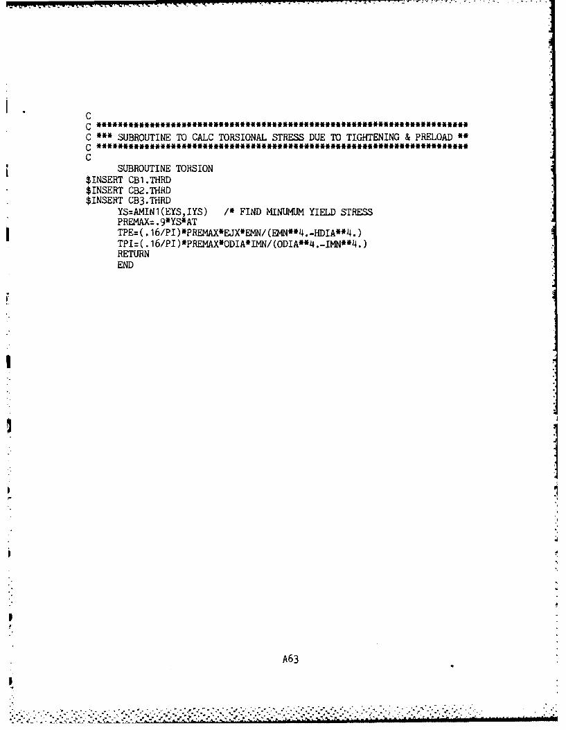
CC '~SUBROUTINE TO CALC TORSIONAL STRESS DUE TO TIGHTENING & PRELOAD"
C
SUBROUTINE TORSION$ INSERT OCl .THRD$INSERT CB2.THRD$INSERT CB3.THRD
YS=AMIN1(EYS,IYS) I' FIND MINUMUM YIELD STRESSPREMAX: .9*YS*AT
j TPE= (. 16/PI )*PREMAX*EJXIEMN/(EMN**I.-HDIA**4.)TPI= ( .16/PI )VPREMAX*ODIA*IMN/(ODIA*14.-IMN**4.)RETURNEND
A6 3
- - - - - - -- . . . . . -
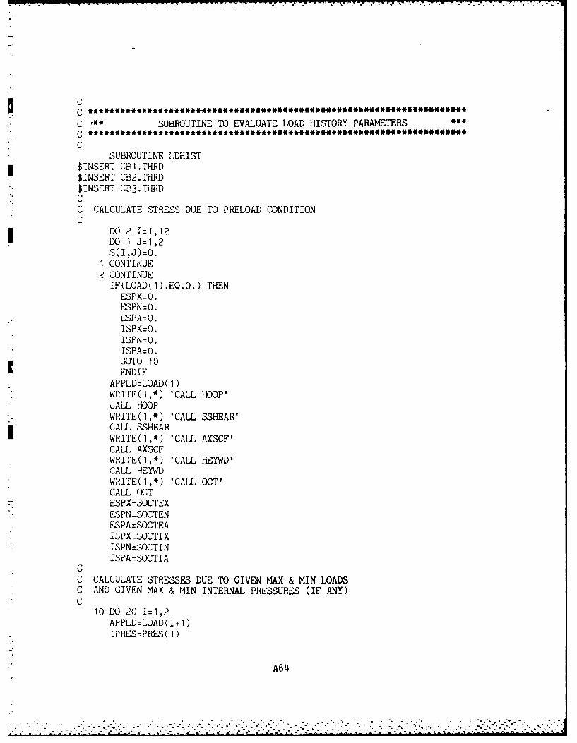
C
C rI* SUBROUTINE TO EVALUATE LOAD HISTORY PARAMETERS* C
CSUBROUTINE LDHIST
$INSERT CBI.THRD$INSERT CB2.THRD$INSERT CB3.THRDCC CALCULATE STRESS DUE TO PRELOAD CONDITIONC
DO 2 I1,12DO 1 J=1,2S(I,J)=O.
1 CONTINUE
2 CONTINUEIF(LOAD(1).EQ.0.) THENESPX=0.ESPN=O.ESPA=O.ISPX:O.
ISPN=O.ISPA=O.GOTO 10ENDIF
APPLD=LOAD(1)WRITE(1,*) 'CALL HOOP'CALL HOOPWRITE(1,*) 'CALL SSHEAR'CALL SSHEAR
WRITE(I,*) 'CALL AXSCF'CALL AXSCFWRITE(I,*) 'CALL HEYWD'CALL HEYWDWRITE(I,*) 'CALL OCT'CALL OCTESPX=SOCTEXESPN=SOCTENESPA=SOCTEAISPX=SOCTIXISPN=SOCTINISPA=SOCTIA
CC CALCULATE srRESSES DUE TO GIVEN MAX & MIN LOADSC AND GIVEN MAX & MIN INTERNAL PRESSURES (IF ANY)C
10 DO 20 I1,2APPLD=LUAD(I+1)IPRES=PRES(1)
A64
WRITE(1,*) 'CALL HOOP'CALL HOOPWRITE(1,*) 'CALL SSHEAR'CALL SSHEARWRITE(1,*) 'CALL AXSCF'CALL AXSCFWRITE(1,*) 'CALL HEYWD'CALL HEYW)WfiITE(1,*) 'CALL OCT'CALL OCTS (1 , I)=SOCTEXS (2,I) =SOCTENS(3,I) =SOCTEAS(4,I)=SOCTIXS(5,I)=SOCTINS(6,I)=SOCTIAS(7, I) =TOCTEXS(8, I )TOCTENS(9,I)=TOCTEAS( 1O,I)=TOCTIXS(11,I)=TOCTINS( 12,I)=TOCTIAIF(LOAD(3).EQ.O.) GOTO 30
20 CONTINUE30 MEAN(1)=(ESPX+(S(1,1)+S(1,2))/2.)*100./ETS
MEAN(2)=(ESPN+(S(2, 1)+S(2,2) )/2. )*100./ETSMEAN(3)=(ESPA+(S(3, 1)+S(3,2) )/2. )'100./ETSMEAN(i4)=(ISPX+(S4, 1 )+S(4,2) )/2. )*100./ITSMEAN(5)=(ISPN+(S(5, 1)+S(5,2) )/2. )*100./ITSMEAN(6)=(ISPA+(S(6, 1)+s(6,2))/2. )*100./ITSALT( 1)=( (S( 1,1)-S( 1,2) )/2. )*100./ETSALT(2)=((S(2, 1)-S(2,2) )/2. )*100./ETSALT(3)=((S(3, 1)-S(3,2) )/2. )*100./ETSALT(4)=((S)4, 1)-S(J4,2) )/2. )*100./ITSALT(5)=( (S(5, 1)-S(5,2) )/2. )*100./ITSALT(6)=( (S(6, 1)-S(6,2) )/2. )*100./ITSRETURNEND
A65
A L. I .
CCC SUBROUTINE TO CALCULATE HOOP STRESS ON EXTERNAL MEMBER
CSUBROUTINE HOOPREAL*4 Gi
$INSERT CB1.THRD$INSERT CB2.THRD$INSEiiT GB3.THRD
SHEX=(2.*PRESo(l)*(HDIA)**2.)/(EMX**2.-.HDIA**2.)SHEN=(2.*PRES( 1)*(HDIA)**2. )/(EMN**2.-HDIA**2.)IF((EMA.GE.EMN.AND.EMA.LE.EMX).OR.EMA.EQ.O.) Gl=EMNIF((EMA.LT.EMtN.AND.EMA.NE.O.).OR.EIA.GT.EMX) Gl=EMASHEA(2.*PHES(1)*(HDIA)**2.)/(G1**2.-HDIA**2.)RETURNEND
A66
t.R.,.... I
CC SUBROU~I NE TO CALCULATE SHEAR AREAS AND STRiiEGTHS * * ** I* *
CC
SUBROUTINE SSHEAR$INSERT CB1.THR)$INSERT CB2.THRD$INSERT CB3.THRDC ETS - EXTERNAL MEMBER TENSILE STRENGTHC ITS - INTERNAL MEMBER TENSILE STRENGTH
IF(ETS.EQ.ITS) THEN /* EQUAL INT & EXT STRENGTHHELIXS=N*LE*( (PI*IPN)**2.+PITCH**2. )**.5ASHEAR=HELIXS/ (2. *N)END IF
IF(ETS.GT.ITS) THEN /* EXT STRENGTH GREATERHELIXS=N*LE*((PI*EJN)**2.+PITCH**2. )**.5ASHEAR= .5*HELIXS*(PITCH+(TAN(PFRAD)+TAN(CLRAD) )*(EJN-.IPX))ENDIF
IF(ITS.GT.ETS) THEN /* INT STRENGTH GREATERHELIXS=N*LE*((PI*IMX)**2.+PITCH**2. )**.5ASHEAR= . 5HELIXS' (PITCH+ (TAN (PFRAD )+TAN (CLRAD) )*~(EPN-IMX))ENDIF
SSTRESS=LOAD (2) /ASHEARRETURNEND
A67
C
C SU6ROUTINE TO CALCULATE AXIAL STRESS CONCENTRATION FACTORC AND F~ILLET STRESS AT THREAD HOOT AREA DUE TO AXIAL LOAD
SUBROUTINE AXSCFREAL*4 (At4A,VAR,VAR2,WVAR3,Kl,WO,W1,W2,K2
$INSEHT CB1.THRD$INSERT CB2.rH-RD$INSERT CB3.'HHD
GAHM=~ .3* (PITCH/HE1 ).7WVAR1=( (GPt44A*HE/ERH)**.5)*.6
4VAHi3=4*GAMM~A*HE 1/ERRK1=W4VAH1*WVAHi2/( (WVAR3+.09*(WVAR2)**2. )**.5)'WQ=1.-((PFANG+CLANG)/18.)**(.+2.4*(ERR/(GA41A*HEl))**.5)'W I=((ElMX/2. /ERR) **. 5) -1.v42=((EMN/2./EPR)**.5)-1.IF(EMA.GriMEX.OR.(EMA.LTF.EMN.AND.EMA.NE.O.)) Gl=EMAIF( (EAIA.Li.BX.AND.FZA.GE.FIN).OR.EMA.E-Q.O.) Gl=EMN
*(2-*P!/3.2*PRAD)KAEN= 1.+( (1 .25*(KI1.)*W2*WO)/( (K1- . )**2.+1 .5625*W2*2. )**.5)*COS*(2.*PI/3.2*PF~RAD)KAEA= 1.-.((1 .25*(K1-l )*W3*WO)/( (K1-1 )**2.+1 .5625*W3**2..)**.5)*COS
KNEX 1 .+( (1 .25*(K1.)*Wl*WO)/( (Kl-l1 )**2.+1 .5625*Wl**2. )*.5)IF(KAEX.LT.1.) KAEXz1.IF(KAiEN.LT.1.) KAEN=l.IF(KAE-A.LT.1.) KAEA=1.3ThEX=KAEX*APPLD*(4./PE)/(EMX**2.-HDIA**2.)"'FEN=KAEN*APPLD*(4./PI )/(jytJ**2-HDIA**2.)ST'EA=KAA*APPLD*(4./PI)/(Gl**2.-HDIA**2.)6AMA=3*(PITCi/HI1 )**-7WVA81=( (GAM\A*HI/IRR)**5)*.b
YiVAIH 3= *GAMA4A*Hi 1 /IRRK -'=VArHI1WVAR2/( (WVAR3+.09*(WVAR2)**2. )**.5)'WO 1 .- ( (PF'ANG+CLANG)/18O. )**(l1.+2.4*(IRR/(GAI41A*HI ) )**.5)
W2= 1b')*((IJX/2./IHH)**.5)-..5lii IJA.GT.IJX.OR. (IJA.LT.IJN.AND.IJA.NE.O.)) Gl=IJAIF(IJA.W,.O. .Ji. (IJA.LE.ILJX.AND.IJA.GE.IJN)) Gl=IJX
A68
W3(.66*/3. 2.FR)*.)5KAIN:1.+((K2-1.)*W2*WQ/((K2-1. )**.2+W2**2.)**.5)*COS*(2.*PI/3..APFRAD)KAIA=1..i((K21.)W3WO/((K2-1.)**.2+W2**2.)**.5)*CQS
*(2.*PI/3.-2.*PFRAD)
IF(KAIX.LT.1.) KAIEX=1.IF(KAIN.LT.1.) KAIN:1.IF(KAIA.LT.1.) KAIA=l.STIX=KAIX*APPLD*(i4./PI)/(ODIA**2.-IJN**2.)STIIN=KAIN*APPLD*(4. /PI )/ (ODIA**2.-IJX*t2.)STIA=KAIA*APPLD*(LL/PI)/(ODIA**2.-Gl**2.)RETURNEND
A69
C* C SUBROUTINJE TO CALCULATE VARIABLES USED IN HEYWOOD'S EQUATION '* C
CSUBROUTINE HEYWDREAL*14 V,V2,V3,Ul,U2,U3,Gl,U4*DlEX,DlEN,DlEA,DlIX,DlIN,DlIA,PO,U5,U6,U7,U8,Y,Z,*SBEX(7),SBEN(7),SBEA(7),SBIX(7),SBIN(7),SBIA(7)
$INSERT CB1.THRD$INSERT CB2.THRD$IPJSERT CB3.THRDCC CALCULATION OF E PARAMETER
* C
V2=SiN( (PFRAD+CLRAD)/2.)V3=COS(PFRAD)EEXz ( (HV-SEMAX-ERR*V )/V3 )*V2iZEN: ((HV-SEMIN-EiHR*V) /V3 ) W2EEAZ( (HV-SEMIN-ERR*V)/V3)*V2EIx=( (IHvSIMAX-IRR*V)/V3)*V2EIN=( (HV-SIMIN-IRR*V)/V3)*V2EIA=( (HV-SIMIN-IRR*V)/V3)*V2
CC CALCULATION OF MlC
Ul=TAN(PI/14.-(PFRAD/2.))+TAN(PI/J4.-(CLRAD/2.))-SIN(PI/3.-CPFRAD))*-SIN(PI/3.-CLRAD)U2=PITCH/2.U3='rAN (PFiiAD )+TAN (CLRAD)Ml EX=ERR*U 1+U2+U3* (EPX-EMX ) *5M1lEN=ERR*Ul+U2+U3*(EPN-EMN)*.5IF(EPA.GT.EPX.OR.(EPA.LT.EPN.AND.EPA.NE.O.)) Zl=EPAIF((EPA.LE.EPX.AND.EPA.GE.EPN).OR.EPA.EQ.O.) Zl=EPNIF(EM A.GTr.EMX.oH. (EMA.LT.EMN.AND.EMA.NE.O.)) Z2=EMAIF((A.LE.4X.AND.EMA.GE.Ek'I).OR.EMA.EQ.O.) Z2=EMNGl=(Zl-Z2)*.5Ml1EA=ERR*U 1+U2+U3*G1Ml IX=IHH*U l+U2+U3*( IJN-IPN)*.5Ml IN=IRR*Ul+U2+U3*(IJX-IPX)*.5IF(IJA.GT.IJX.OR.(IJA.LT.IJN.AND.IJA.NE.O.)) Zl=IJA
* IF((IJA.LE.IJX.AND.IJA.GE.IJN).OR.IJA.EQ.O.) Zl=IJX-IF(IPA.GT.IPX.OR.(IPA.LT.IPN.AND.IPA.NE.O.)) Z2=IPAIw((IPIA.LE.IPX.AND.IPA.GE.IPN).OR.IPA.EQ.O.) Z2:IPX
*Ml IA=I Ri*UI+2+U3*ilCC CALCULATE VALUES FOR THETA
* C
A70
IF (SERIES.EQ. 4.OR.SERI&,. EQ 5) THENU4=COS(PI/3.-CLRAD)-CO)S(PI/3.-PiRfAD)ETHIETAX=ATAN ((ERR*U4 )/Ml1EX;ETHETAN=ATAN( (FRU4)/MlEN)ETHETAA=ATAN( (ERR*U4)/M lEA)ITdETAX=ATAN( (IRR*UL4)/M1IX)ITHETAN=ATAN ( (ARR*U4) /Ml1 N)ITHETAA=ATAN ( ( ER0 U4) /Ml1IA)
Cc; CALCULATE VALUES FOR DlC
* DlEX=MlEX/COS(ETHETAX)DlEN=M1EN/COS(ET'HETAN)
* . DlEA=MlEA/COS(ETHETAA)Dl IX=M1 IX/COS( ITHETAX)Dl IN=M1IN/GOS( ITHETA4)
* D1IA=M1IA/COS( ITHETAA)ELSE
9 DlEX=MlEXD1EN=M1END1EA=M lEAD1IX=MlIXDl1N=MlIND1IA=MlIAENDI F
* CC CALCULATE VALUES FOR D' (EXT THRD)C
PO=(t&JN-IMX)' .05*COS(PFRAD)DPEX( 1)=(EJX-IMN)/4.+(IMv-EMX)/2.DPEN( 1)=(EJN-IMX)/4.+(IMX-E1N)/2.IF(EMA.GT.EM'X.OR.(EMA.LT.EMN.AND.FI1A.NE.O.)) G1=EMAIF(EM1A.EQ.O. .OR. (EMA.LE.E'4X.AND.E2MA.GE.EMN)) Gl=EMNDPEA( 1 )(EJN-IMX)/4.+(IMX-G1 )/2.DPEX(2)=DPEX( 1)+PO*.5629DPEN(2)=DPEN( 1)+PO*.5629DPEA(2)=DPEA( 1)+PO*.5629DPEX(3)=DPEX(l)-PO*.5629DPEN(3)=DPEN(l)-PO*.5629DPEA(3)=DPEA(1)-PO*.5629DPEX(L4)=DPEX( 1)+PO*1 .11974DPEN(L4)=DPEN( 1)+PO*1 .119Th
f DPEA(J4)=DPEA(1)+PO*1.11974DPEX(5)=DPEX(l1)-PO*1 .11974DPEN(5)=DPEN(l1)-PO*1 .119ThDPEA(5)=DPEA(l1)-PO*1 .119ThDPEX(6)=DPEX(1)+PO1.6241DPEN(6)=DPEN(1)+PO*1.6241
U DPEA(6)=DPEA(1)+PO*1.6241DPEX(7)=DPEX(l1)-PO*1 .6241
A7 1
DFEN(7)=DPEN(1)-PO*1 .62141DPEA(7)=DPHA(l1)-PO1.6214'
C CALCULATE iiix AT POINT OF APPLIED LOADC
P'X( 1) 7N,*IA. ft((P'i*(EM~X+.*DPEX(1)))**2 +PTCH*2.)**.5PTN4(1>=N*Li'*((PI*(El2N..DPEN()))*2...PITCH*2.)**.5
- -P"A( ,:N*LEF*((PI*(G1+2.*DPEA()))**2.+PITCH**2.)**.5- TX,""')=;*E((PI*(EI+2.*DPEX(2)))**2.+PITCH*2.)**.5
PTN(\2)ziN*LIIF((PI*(EMN+2.*DPEN(2)))**2.+PITCH*2.)**.5- -PTA(2)=N*LE*& ,Pl*(Gl+2.*DPEA(2)))**2.+PITCH**2.)**.5
PTFX(3)=N*LE*( (Pl*(EMX+2.*DPEX(3) ))**2.+PITCHI*02.)**.5PTN(3)=N*LE*(( PI*(EMN+2.*DPEN(3)))**2.+PITCH**2.)**.5F'rA(3)=N*LE*((PI*(Gl+2.*DPEA(3) ))**2.+PITCH*V.)**.5PTX(41=>W*LE*((PI*(EMX+2.*DPEX(14)))**2.+PITCH*2'.)*.5,PTN(4)=:*L-E*((PL *(EMN+2.*DPEN(4)))**2.+PITCH*K2.)**.5
PTA4)N*LE*( (PI*(G1+2.*DPEA(4) ))**2.+PITCH**2. )*PTX(5)=N*LL'*( (PI*(EMX+2.*DPEX(5)))**2.+PiTrCH**2.)**.5
* FiN(5)>N*LE*((Pl*(EMN+2.*DPEN(5)))*2.+PITCH2.)**.5PTA(5-)=N*LE*((PI*(Gl+2.*DPE-A(5)))**2.+PITCH**2.)**.5PTX(6)):.N*LE*((Pl*(EMX+2.*DPEX(6)))**2.+PITCH**2.)**.5
* PTN(6)=N*LE*((PI*(EMN+2.*DPEN(6)))**2.+PITCrA**2.)**.5* PTA(6)=N*LE*((PI*(Gl+2.*DPEA(6)))**2.+PITCH**2.)**.5
PTX(7)=N*LE*((PI*(EMX+2.*DPEX(7)))**2.+PITCH**2.)I*.5PTN(7)=i*LE*((Pl*(EMN+2.*DPEN(7)))**2.+PITCH**2.)**.5PTA(7)=N*LE*((Pl*(Gl+2.*DPEA(7)))**2.+PITCH**2.)**.5
CC CALCULATE VALUES FOR D' (INT THRD)C
DPIX( 1 )(IJN-EJX)/2.+(EJX-IMN)/4.DPIN( 1 )(IJX-EJN)/2.s(EJN-IMX)/4.IF((IJA.L'T.IJN.AND.IJA.NE.O.).OR.IJA.GT.IJN) Gl=IJA
* IE(IJA.EQ.O. .OH.(IJA.LE.IJX.AND.IJA.GE.IJN)) Gl=IJXDPIA(1)=(GI-EJN)/2.+(EJN-IMX)/4.DPIX(2)=DPIX(1)+PO*.5629DPIN(2)=DPIN(I1)+PO*.5629DPIA(2)=DPIA( 1)+PO*.5629DPIX(3)=DPIX(1)-~PO*.5629DPIN(3)=DPIN( 1)-PO*.5629DPIA(3)=DPIA( 1)-PO*.5629DPIX('4)=DPIX(1 ).ePO*1 .11974DPIN('4)=DPIN( 1)+PO*1 .119714
* DPIA(4)PIA(1)+PO*1*11974DPIX(5)=DPIX(1)-P*1.11974DPIN(5>)PIN(l)-P01.11974
DPIX(6)=DFIX(l).PO*1.241- . DPIN(6)=DPIN(lY.P0*1.6241
DPIA(6)=DPIA(1)+PO*1.6241DPIX(7f)=DPIX(l)-PO*1.6241
A72
DPIN(7=DPIN(1)-P'1.6241DPIA(7=DPIA( 1)-Po'i .6241
C CALCULATION OF B & AU5=TAN(PI/L4.-PFRAD/2.)U6=SIN( P1/3. -PFRAD)U7=TAN( PFRAD)U8=COS(PFRAD)Y=ERRZ=IRRDO 10 I=1,7 2BEX(I)=(DPEX(I)-Y*V)/COS(ATAN((DPEX(I)*U7+Y*U5-Y*U6)/(DPEX(I)-Y*V)
BEN(I)=(DPEN(I)-Y*V)/COS(ATAN( (DPEN(I)*U7+Y*U5-Y*U6)/(DPE4(IE)-Y*V)
BEA(I)=(DPEA(I)-Y*V)/COS(ATAN((DPEA(I)*U7+Y*U5-Y*U6)/(DPEA(I)-Y*V)
I)=DI()ZV/O(TN(PXI*7ZU-*6/DI()*)
BIX(I)=(DPIX(I)-Z*V)/COS(ATAN((DPI(I)*U7+Z*U5-Z*J6)/(DPIX(I)-Z*V)
BIN(I)=(DPIN(I)-Z*V)/COS(ATAN((DPIA(I)*U7+Z*U5-Z*U6)/(DPIN(I)-Z*V)
BA(I)=(DPIA(I)-Z*V)/USATN(PA(I)IU7+ZN*U5DZ*U/.Y(PIA()Z)AE))=(PAI-*6/8SNPRDEHTA*DE/.Y(5u
AEX(I)=(DPEX(I)-Y0U6)/U8-SIN(PFRAD+ETHETAX)*(D1EX/2.-Y*t(U5-U6))AI()(PN()ZU)U-SNPRDIHEA).lN2.Z(5U)AEA(I)=(DPEA(I)-Y'U6)/U8-SIN(PFRAD+ETHETAA)*(DlEA/2.-Y*(U5-U6))
10 CONTINUECC CALCULATE KB (FILLET STRESS CONCENTRATION FACTOR)C
KBEX ( 1.+. 26 (EEX/Y)) *.7KBEN=(l1.+.26*(EEN/Y) )**.7KBEA=(l1.+.26*(EEA/Y) )**.7KBIX=(l1.+.26*(EIX/Z) )**.7KBIN=(l1.+.26*(EIN/Z) )**.7KBIA=(1 .+.26*(EIA/Z))**.7
CC CALCULATE SECOND COEFF TERN IN HEYWOOD EQC
TlX(1)=.2128*APPLD/PTX(1)/COS(PFRAD)T1N( 1)=.2128*APPLD/PTN( 1)/COS(PFRAD)T1A(1)=.2128*APPLD/PTA(1)/COS(PFRAD)TlX(2)=. 1953*APPLD/PTX(2)/COS(PFRAD)T1N(2)=. 1953*APPLD/PTN(2)/COS(PFRAD)T1A(2)=. 1953*APPLD/PTA(2)/COS(PFRAD)TlX(3)=.1953*APPLD/PTX(3)/COS(PFRAD)TlN(3)=. 1953*APPLD/PTN(3)/COS(PFRAD)
T1A(3)=. 1953*APPLD/PTA(3)/COS(PFRAD)
A7 3
T1X(J4)=.. .... A.D/T()/O(PRD
TIN(4)=. 1428APPLD/PTN('4)/COS(PFRAD)T1A(14)=. 1L28APPLD/PTA(i4)/COS(PFRAD)TIX(5)=. 1428*APPLD/PTX(4)/COS(PFRAD)TIN(5)=. 1428APPLD/PTN(5)/COS(PFRAD)T1A(5)=. 1428APPLD/PTA(5)/COS(PFRAD)T1X(6)= .014*APPLD/PTX(6)/COS(PFRAD)
-' TlN(6)= .0554APPLD/PTN(6)/GOS(PFRAD)TlA(6)= .0554*APPLD/PTA(6)/COS(PFRAD)TlX(6)=.0554*APPLD/PTX(7)/COS(PFRAD)TlN(7)= .0554*APPLD/PTN(7)/COS(PFRAD)TIA(7): .0554*APPLD/PTA(7)/COS(PFRAD)
CC CALCULATE 1ST TERM INSIDE BRACKETS IN HEYWOODS, EQUATIONC
DO 20 I=1,7T2EX( I)= 1.5*AEX(I )/EEX**2.T2EN(I)=1 .5*AEN(I)/EEN**2.T2EA(I)=1.5*AEA(I)/EEA**2.
T2IN(I)=1 .5*AIN(I)/EIN**2.
T21A(I)=1 .5*AIA(I)/EA*2.CC CALCULATE 2ND TERM INSIDE BRACKETS IN HEYWOOD EQUATIONC
T3EX(I): .451(BEX(I)*EEX)**.5T3EN(I)=.145/(BEN(I)*EEN)**.5T3EA(I)=.45/(BEA(I)EEA)"*.5
T31X(I)=.45/(BI(I)EIX)**.5
Cc CALCULATE 3RD TERM INSIDE BRACKETS IN HEYWOOD EQUATIONC
T4EX(I)=.5/(2.EEX) /* NOTE: FOR LOAD NORMAL TO PF, PHI=30T4EN(I)=.5/(2.*EEN)T4EA(I)=.5/(2.*EEA)T41X(I)=.5/(2.*EIX)T41N(I)=.5/(2.*EIN)T41A(I)=.5/(2.*EIA)
CC CALCULATE HOOT STRESS FORM VALUES
* CSBEX(I)=KBEX'TlX(I )*(T2EX(I)+T3EX(I)+T4iEX(I))SBEN( r)=KBEN*TlN(I)*(T2EN(I)+T3EN(I)+T4EN(I))SBEA(I)=KBEA*TIA(I)*(T2EA(I)+T3EA(I)+T4EA(I))SBIX(I)=KBIX*'rlN(I)*(T2IX(I)+T3IX(I)+T4IX(I))
U SBIA(I)=KBIA*T1A(I)#(T2IA(I)+T3IA(I)+T4IA(I))
20 CONTINUE
A7~4
CC CALCULATE COMBINED TOTAL SB DUE TO PARABOLIC LOAD DISTRIBUTIONC
SBEXT=SBEX( 1)+SBEX(2)+SBEX(3)+SBEX(4)+SBEX(5)+SBEX(6)+SBEX(7)SBEXT=TLCF*SBEXTSBENT=SBEN( 1 )-SBEN(2)+SBEN( 3)+SBEN(4)+SBEN(5)+SBEN(6)+SBEN(7)SBENT=TLCF*SBENTSBEAT=SBEA( 1)+SBEA(2)+SBEA(3)+SBEA(4)+SBEA(5).SBEA(6)+SBEA(7)SBEAT=TLCF*SBEATSBIXT=SBIX( 1)+SBIX(2)+SBIX(3)+SBIX(J4)+SBIX(5)+SBIX(6)+SBIX(7)SBIXT=TLCF*SBIXTSBINT=SBIN( 1)+SBIN(2)aSBIN( 3)+SBIN(J4)+SBIN(5)+SBIN(6)+SBIN(7)
* . SBINT=TLCF*SBINTSBIAT=SBIA( 1)+SBIA(2)+SBIA(3)+SBIA(I)+SBIA(5)oSBIA(6)+SBIA(7)
* SBIAT=TLCF*SBIATRETURNEND
A75
CC *********w*****~*IiI*******i*uE***C SUBROUTINE TO CALC HYDROSTATIC TENSION & PURE SHEAR ON ANC OCTAHEDRAL PLANE 1C
C SUBROUTINE OCT
$INSERT CB1.THRD$INSERT CB2.THRD$INSERT CB3.THRD
SOC'TEX= (1 ./3. ) *(SBEXT+STEX+SHEX)SOCTEN=( 1.13. )*(SBENT+STEN+SHEN)SOCTEA=( 1.13. )*(SBEA-.STEA+SHEA)SOCrIX=( 1.13. )*(SBIXTsSTIX)SOCTIN=( 1.13. )*(SBINT+STIN)SOCTIA=( 1 /3 )*(SBIAT+STIA)TOCTEX (1 ./ 3. ) *(SBEXT+STEX-SHEX)TOCThN= (1./3.) *(SBENT+STEN-SHEN)
* T~'OCT.Az(1 .13. )* (SBEAT+STEA-SHEA)TUCTIX=( 1.13. )*(SBIXT+STIx)TOCFIN=( 1.13. )*(SBINT+STIN)TOCTlA= (l 1/3.) *(SBIAT+,STIA)HE'PUHNEND
A76
C
C
C SUBROUTINE TO CALCULATE STATIC SAFETY FACTORS WRT Y.S & T.S. ~* C *~AND LOAD CAPACITIES
CC
SUBROUTINE STATSFi ISR B.fR
$INSERT CB2.THRD* $INSERT CB2.TH-RD
$ST CB3.THRD~lSFlYEX:EYS/S( 1,1)SFlYEN=EYS/S(2, 1)
SFlYIX=IYS/S(4,1)SE'1YIN=IYS/S(5, 1)SFlYIA=IYS/S(6, 1)SF2YEX=.577*EYS/S(7, 1)SF2YEN=.577*EYS/S(8, 1)SF2YEA-- 577*EYS/S (9, 1)
p. SF2YIX=.577*IYS/S (10, 1)SF2YIN=.577*IYS/S( 11,1)SF2YIA= .577'*IYS/S( 12, 1)SFlTEX=ETS/S( 1,1)SF1TEN=ETS/S(2, 1)SFlTEA=ETS/S(3, 1)
* SFITIX=ITS/S(4,1)SF1TIN=ITS/S(5,1)SFlTIA=ITS/S(6, 1)SF2TEX=.577*ETS/S(7, 1)SF2TEN=.577*ETS/S(8, 1)SF2TEA=.577*ETS/S(9, 1)
0 SF2TIX=.577*ITS/S( 10,1)SF2TIN=.577*ITS/S( 11,1)SF2TIA: .577*ITS/S( 12, 1)SFYEX=AMIN1 (SF1YEX,SF2YEX)SFYEN=AMIN1 (SF 1YEN,SF2YEN)SFYEA=AMIN1I(SF 1YEA ,SF2YEA)
p SFYIX=AMIN1 (SF 1YIX,SF2YIX)SFYIN=AMIN1 (SF1YIN,SF2YIN)
SFYIA=AMIN 1(SF lYIA ,SF2YIA)ISFTEX=AMIN1 (SF 1TEX,SF2TEX)SFTEN=AMIN1 (SFlTEN,SF2TEN)SFTEA=AMIN1 (SFlTEA,SF2TEA)SFTIX=AMIN1 (SF1TIX,SF2TIX)SFTIN=AMIN1 (SF 1TIN,SF2TIN)SFTIA=AMIN1 (SF 1TIA,SF2TIA)SFY=AMIN1 (SFYEX,SFYEN ,SFYEA ,SFYIX,SFYIN,SFYIA)SFT=AMIN1(SFTEX,SFTEN,SFTEA,SFTIX,SFTIN,SFTIA)CAPPLD( 1) =LOAD(2) 'SFYEX
P CAPPLD(2)=LOAD(2)*SFTEX
A77
V, T T- -7 T- - --- N~
CAPPLD(3)=LOAD(2)*SFYEN
CAPPLD(4)=LOAD(2)*SFrENCAPPLD(5)=LOAD(2)*SFYEACAPPLD(6 )=LOAD(2 )*SF'TEACAPPLD(7 )=LOAD(2)*SFYIXCAPPLD(8)=LOAD(2)*SFTIXCAPPLD(9)=LOAD'2)*SFYINCAPPLD( 1O)=LUAD(2)*SFTINCAPPLD( 11 )=LOAD(2)*SFYIACAPPLD( 12)=LOAD(2)*SFTIACAPPLD( 13)=AMIN1 (CAPPLD(1) ,CAPPLD(3) ,CAPPLD(5) ,CAPPLD(7) ,CAPPLD(9)
*,CAPPLD(11))CAPPLD( 14)=AMIN1 (CAPPLD(2) ,CAPPLD('4) ,CAPPLD(6) ,CAPPLD(8) ,CAPPLD( 10
*),CAPPLD(12))LDYE=EYS/SSTRESS*LOAD (2)LDYI = IYS/SSTRiESS*LOAD (2)LDTE=ETS/SSTRESS*LOAD (2)LDTI=ITS/SSTRESS*LOAD (2)RETURNEND
A78
- *6~~ "
C
C ''SUBROUTINE TO~ GENERATE NOTCH SENSITIVITY FACTORS GIVEN RADIUS IC AND ULTIMATE STRENGTH OF THE MATERIAL
CSUBROUTINE NOTCHRf'AL*4 ARH(16,11)INTEGER*4 EC,IC
$INSERT CB1.THHD$INSERT OB2.THH)$INSERT CB3.ThHD
DATA ((ARR(I,J), I=13116), J=1,11)/.0025,.005,.0075,.01,.015,.02,.O*3, .014,.05, .06, .07,.08, .1,. 12,.14, .16,.7i41,.808, .835,.855, .881,.894*,.91,.92, .92o, .932, .938,.944,.949, .95J4,.957, .963, .680,.756, .785, .8'10, .8240, .855, .876, .890, .9, .908,.915,.922,.929,.935, .914,.9145, .62, .7'03, .735, .764, .798, .815, .8243, .861, .873, .883, .892, .901,.908, .917, .92'2, .926, .559, .b1, .635, .719, .757, .776, .809, .831, .347, .859, .869, .879*,.8, .8,.904, .903, .4914,.592, .632, .666, .706, .730, .765, .791,.810,*.824, .837, .8146, .918, .926, .931, .935, .429, .532, .58, .613, .656, .684,.7'24, .751, .7724, .79, .805, .614, .831, .843, .853, .86, .386, .468, .522, .553,*.599, .632, .678, .712, .735, .754, .766, .778, .798, .813, .833, .835, .356,.'242, .467, .496, .5142, .574, .623, .659, .686, .704, .721,.737, .758, .775, .78'5, .797, .257, .3147, .398, .4314, .42, .519, .569, .607, .633, .655, .672, .688*,.709,.726,.739,.752,.079,.18,.247,.295,.366,.417,.491,.546,.582,.'615, .641 ,.667, .723, .76, .789, .81/
CC SELECT PROPER NOTCH SENSITIVITY CURVES BASED ON MAT'L STRENGTHSC
IF(E-TS.GT.200.) EC=2IF(ETS.GE. 160. .AND.ETS.LT.200.) EC=3IF(ETS.GE. ba. .AND.ETS.LT. 180.) EC=~4IF(ETS.GE.140. .AND.ETS.LT. 160.) ECz5IF(ETS.GE.120..AND.ETS.LT.140.) EC=6IF(ETS.GE.100..AND.ETS.LT.120.) EC=7IF(ETS.GE.80..AND.ETS.LT.100.) EC=8IF(ETS.GE.60. .AND.ETS.LT.80.) EC:9IF(ETS.GE.50..AND.ETS.LT.60.) EC=10IF(ITS.GT.200.) IC=2IF(ITS.GE.160. .AND.TTS.LT.200.) IC=3IF(ITS.GE.160..AND.ITS.LT.180.) IC=4IF(ITS.GE.140. .AND.ITS.LT. 160.) IC=5IF(ITS.GE.120. .AND.ITS.LT.1140.) IC=6IF(ITS.GE.100. .AND.ITS.LT.120.) ICz7IF(ITS.GE.8o..AND.ITS.LT.loo.) IC=8
A79
IF(-T-.G .60 - -N-ITS- .o- i c .
IF(ITS.GE.60. AND.ITS.LT.8O.) IC=90
CC EVALUATE NOTCH SENSITIVITY VALUES (EXTERNAL THREAD)C
IF(ERR.LT. .0025) THENEQ=(AHR( 1,EC)/.0025)*ERRGOTO 30ENDIF
DO 10, I=2,16IF(ERR.GE.ARR(I-1,1).AND.ERR.LT.ARR(I,1)) GOTO 20
10 CONTINUEWRITE(1,*) 'ERROR IN SUBROUTINE NOTCH.'STOP
20 EQ=ARR(I-1,EC)+((ARR(I,EC)-ARR(I-1,EC))/(ARR(I,1)-ARR(I-1,1)))*(ER*R..ARR(I-.1 ,1))
CC EVALUATE NOTCH SENSITIVITY VALUES (INTERNAL THREAD)C
30 IF(IRR.LT. .0025) THENIQ=(ARR( 1,IC)/.0025)*IRRGOTO 70ENDIF
DO 40, I=2,16IF(IRR.GE.ARR(I-1,1).AND.IRR.LT.ARR(I,1)) GOTO 60
40 CONTINUEWRITE(1,*) 'ERROR IN SUBROUTINE NOTCH.'STOP
60 IQ=ARR(I-1 ,IC)+((ARR(I,IC)-ARR(I-1,IC))/(ARR(I,1)-ARR(I11,1)))*(IR*R-ARR(I11 ,))
70 RETURNEND
A80
CCC "'SUBROUTINE TO CALCULATE THEORECTICAL STRESS CONCENTRATION FACT 'C "'AND MOD FACTOR DUE TO FATIGUE STRESS C0NC FACTOR
C
SUBROUTINE TSCFREAL*4 KTC(31,2)
$INSERT GB 1 .THRD$INSERT CB2.THRD$INSERT CB3.THRD
DATA ((KTC(I,J),I=1,3),J1,2)/.01,.015,.02,.025,.03,.035,.04,.045*,.05,.055, .06, .065, .07, .075, .08,.085,.09,.095, .1,.11, .12, .13,.14,'15,. 16, .17,. 18, .19, .2, .25, .3,3. ,2.9,2.65,2.55,2.4,2.3,2.2,2. 1,2.05*,2. ,1.92,1.9,1.85,1 .8,1.77,1.75,1.72,1.7,1.68,1.63,1.6,1.57,1.54,1* .51, 1. 48, 1. 46,1. 45 ,1. 43, 1. 41, 1.3,1.26/IF(ERR/EMN.LT..O1) THENKNEX=3.GOTO 30FIND IF
DO 10, I=1,30IF(ERR/EMN.GE.KTC(I,1).ANlD.ERR/EMN.LT.KTC(I+1,1)) GOTO 20
10 CONTINUESTOP
20 KNEX=KTC(I,2)30 IF(IRII/IMN.LT. .01) THEN
KNIX=3.GOTO 60ENDIF
DO 40, I=1,30IF(IRR/IMN.GE.KTrC(i,l).AND.IRR/IMN.LT.KTC(I+1,1)) GOTO 50
40 CONTINUESTOP
50 KNIX=KTC(I,2)60 KQEX=1.-.EQ*(KNEX-1.)
KQEN=1 .+EQ*(KNEX-1.)KQEA=1 .+EQ*(KNEX-1.)KQIX=1 .+IQ*(KNIX-1.)KQIN=1 .+IQ*(KNIX-1.)KQIA=1 .+IQ*(KNIX-1.)KPEX=(KQEX-1. )*( .12+.0038*(ETS-100. ))+1.KPEN=(KQEN-1 .)*( .12+.0038*(ETS-100. ) )-1.KPEA=(KQEA-1.)*(. 12+.0038*(ETS-100. ))+1.KPIX=(KQIX-1. )*(. 12+.0038*(ITS-100. ))+1.KPIN=(KQIN-1.)*( .12+.0038*(ITS-100. ))+1.KPIA=(KQIA-1 . )( .12+.0038*(ITS-100. ))+1.KFEX( 1 )KPEXKFEN( 1)=KPENKFEA( 1)=KPEAKFIX( 1)=KPIX
A8 1
KFIN. 1 ) zKP INKFIA( 1)=KPIAKFEX(2>l)KPEX+(KQEX-KPEX)*(ALOG1O(3OOO. )-3. )/3.KFtN(2)KPEN+(KQEN-KPEN)*(ALO)G1O(3OOO. )-3. )/3.KFEA( X)KPA+(KQEA-KPEA)*(ALOG1O(3OOO. )-3. )/3.KFIX(C')=KPIX+(KQIX-KPIX)*(ALOG10(3QOO. )-3. )/3.KPIN(2)~ =k~)N+ (QIN-KPIN)* (ALC)G1O(3OOO.)-3.)/3.
KFEX( 3)=KPEX+(KQEX-KPEX)/3.iKFENJ(3) =KPEN+ 'K QiN-KPEN)/3.KFi'kh(3) =KP:-.A+ K KQI-A-KPA ) / 3.KFLX( )=KPlX+(KQIX-KPIX)/3.KEIN( 3)=KPIN+(KQIN-KPIN)/3.KFIA( 3)zKPiIA+(KQIA-KPIA)/3.KFEX(4)=KPEX+(KQEX-KPEX)*(ALOG1(4OOO. )-3.)/3.:'EN4(H )=KP N+(KQ EN-KPE'N)*(ALOG1O(4OOO. ).3)/3*KFFA,)K. A-KEAKE)(LGO400)-3. )/3.Ki~x(14>=KPTX+(KQIX-KPIX)*(ALOGIO(4OOO. )-3. )/3.KFIN(14)=KPIN+(KQ)IN-KPIN)*(ALOG1O(J4OOO. )-3. )/3.KFiA(4)=KPIA+(KQIA-KPIA)*(ALOG1O(4OOOO. )-3.)/3.KFEX( )=KPi -,+(KQEX-KPEX)*2./3.KF'EN(b)=KPEA\+(KQEN-KPEN )*2./3.K 'EA') ) :KPi,'A+(KQEA-KPEA)*2./3.KFIX(5 PX4K~EX-KPIX)*2./3.KFL ( )=PIN(QNKIN 2/3.KFIA(5) -KP-KA4(KQIA-~KPIA)*2./3.
KFEA 6 o) =KQE'AKFI'X(b)=KQ IX
rKFliN(1 ) KQlNKF1 A (7o) =?KtlA
KFIX(7 )=KQiXKFIN(7 )=KQIN
A82j
C SUBROUTINE TO CALCULATE FATIGUE LIFE SAFETY FACTORS 1
CC SUBROUTINE USED NEWTON METHOD TO FIND INTERCEPT OF LIFE LINE ANDC SLOPE LINE. 2ND DEGREE POLYNOMIALS ARE USED TO DESCRIBE DATA CURVESC
SUBROUTINE FATIGUEREAL*4 C(7,3),SL(6)
$INSERT CB 1. THRD$INSERT CB2.THRD$INSERT CB3.THRD
DATA ((C(I,J),I=1,7),J1,3)/83.204,75.571,67.1299,b1.0005,*55. 1154,48.421L,L6.24L,.648158,-.L 71915,-. 31LI66 5,-.2Ll5 179,
*-.00360573,-..00303571 ,-.00205357,-.00156593/DO 40 1=1,6 /* MAT'L CONDITIONS
4 ~SL (I) =ATAN (ALT (I) /MEAN (I))DO 30 J=1,7 I' FATIGUE LIFE CURVES
XlC(,3) CJ2)(CJ2-LI)*-.CJ3*(,)*.)(.
*C(J,3))
X=AMAX 1(Xl ,X2)20 YVAL=(C(J,3)*X**2+C(J,2)*X+C(J,1))
IF(I.LE.3) THENYVAL=YVAL*ETS/ 100.
ELSEYVAL=YVALITS/ 100.ENDIF
30 CONTINUE40 CONTINUE
C LOAD CONSTANTCL=.9 /* REVERSED AXIAL LOADS W/O BENDING
C SIZE EFFECTCD=1.0 I' AXIAL LOAD
C SURFACE FINISH EFFECTC MIRROR-POLISHED FINISH
IF(ESURF.EQ.1) ECF=l.
C FINE GROUND FINISHIF(ESURF.EQ.2.AND.ETS.LE.170.) ECF=.9IF(ISURF.EQ.2.AND.ITS.LE.170.) ICF=.9IF(ESUR.F.EQ.2.AND.ETS.GT.17o.) ECF=-.0O2'TS+1.24IF(ISURF.EQ.2.AND.ITS.GT.170.) ICF=-.OO2*TTS+1.24
c MACHINED FINISHIF(ESURF.EQ.3.AND.ETS.LE.200.) ECF=-.0012ES+.87IF(ISURF.EQ.3.AND.ITS.LE.200.) ICF=-.0012*'TS+.87IF(ESURF.EQ.3.AND.ETS.GT.200.) ECF=-.002*ETS+1.06
A8 3
_k A
IF(S'JF.1Q.~~N.IT.GT2O0) CF=-.O02*iTs+l.06C HOT ROLLED FINiSH
IF(ESURF.EQ.14.AND.ErFs.LE.140.) ECF=-.O035*ETS+.95IF(ISURF'.Ec.4.Au4D.I'FS.LE.14O.) ICF=-.OO35*ITS+.95IF(ESR.EQ.14.AND.ETS.GT.140.) ECF=-.0O18*ETS+.72lF(ISURF.EQ.4AND.ITS.G.140.) ICF=-.O018*ITS+.72
C FORGED FINISlllF(E.SURF.EQ.5.AND.ETS.LE. 120.) ECF=-.OO37*ETS+.77IF(ISURF.EQ.5.ANID.IrFS.LE.120.) ICF=-.OO37*ITS+.77
* IF(ES3URF.EQ.LS.AND.ETS.GT. 120.) ECF=-.OO16ETS..567IF(ISLJRF.EQ.5.AND..ITS.GT. 120.) ICF=-.0016*ITS+.567IF(ESURF.EQ.1) ESURFS=&MIRROR POLISH'lF(ISUiiF.EQ. 1) ISURFS='MIRROR POLISH'IF(&SURF.EQ.2) ESURF03'FINE GROUNDIF(ISURF.EQ.2) ISURFS=&FINE GROUNDIF(E.sURF.EQ.3) ESURFS='MACHINEDIF(ISURF.EQ.3) ISURFS='MACHINEDIF(ESURF.EQ.4) ESURFS='HOT ROLLEDIF(ISURF.EQ.4) ISURFS='HOT ROLLEDIF(ESURF.EQ.5) ESURFS='FORGEDIF(ISURF.EQ.5) ISURFS='FORGED
C TEMPERATURE EFFECTIF(TEMP.G'r.1bQ.) CT=62O./(46O.+TEMP)IF(TEMP.LE.160.) CTml.
C RELIABILITY FACTORIF(HEL.EQ. .5) R.IF(REL.EQ. .9) CR=.897
* IF(REil.EQ. .95) CR=.868IF(HEL.EQ. .99) CR=.81~4IF(REL.EQ. .999) CR=.753
*C ESTIMATED (.AFETFY FACTORS FOR VARIOUS FATIGUE LIFEFS.'F( 1,1) =CD*ECF*CL*CT*CR*YVAL/ALT( 1)/KFEX( 1)
'F ,?1)7 'T*CC"F*CL*CT*CR*YVAL/AL T(1/FXF2 t,~~*~FC*TCRYA/L(1)/KFEX(3)
K,F i:C1*-(F'*CL*CT*CR*YVAL/ALT(1)/KFEX(3)FL3F (1,.) lCD*ECF' *CL*CT*CR*YVAL/ALT( 1)/KFEX(5)FSF( 1,'UYKDCL*ECF*CL*CT*CR*YVAL/ALT( 1)/KFEX(6)
* FSF(I ,7)'D*ECF*CL*CT*CR*YVAL/ALT(1 )/KFEX(7')FSF( l, I )zCD,*ECF*C-L*CT*CR*YVAL/ALT(2)/KFEN( 1)FF( -,U)=C*E(.F*CL*CT*CR*YVAL/ALT(2)/KFEN(2)FSF( ))=CD:*EC(F*CL*CT*CR*YVAL/ALT(2)/KF'EN(2)
F") (,)= CD*ECF*CL*CT*CR*YVAL/ALT(2)/KFEN(4)FSF4i %=(D*E(CF*CL*CT*CR*YVAL/ALT(2)/KFEN(5)
F)S =i)C(*EF'*C*CT*CR*YVAL/ALT(2)/KFEN(6)FSF(2, )*ECF*rL*CT*CR*YVAL/ALT(2)/KFEN(7)
FSF(j, )=CD*ECF*CL*CT*CR*YVAL/ALT(3)/KFEN(7)FSF~ r)*ICF*CL*CT*CR*YVAL/ALT(3)/KFEA(2)
FSF( i,'!7"-*iCF*CL*CT*CR*YVAL/ALT(3)/KFEA(2)FSF3 i *iQ 'F*CLI*C'T*CRi*YVAL/ALT(3)/KFEA(4)
FSi' 0,' ) = L)*tC*LCTaCRi*YVAL/ALT (3) /KFEA(5)
A841
~~~~~v V- r0. T' rs 4 W-, ~ ' -* -
FSF( 3, 6)=CD*ECF*CL*CT*CR*YVAL/ALT(3)/KFEA(6)FSF(3, 7)=CD*ECF*CL*CT*CR*YVAL/ALT(3)/KFEA(7)FSF(14, 1 )CD*ICF*CL*CT*CR*YVAL/ALT(4)/KFIX( 1)FSF(4I,2)=CD*ICF*CL*CT*CR*YVAL/ALT(LI)/KFIX(2)FSFUI, 3)=CD*ICF*CL*CT*CR*YVAL/ALT(4)/KFIX(3)FSF(14,4)=CD*ICF*CL*CT*CR*YVAL/ALT(4)/KFIX(4)FSF(14, 5)=CD*ICF*CL*CT*CR*YVAL/ALT(4)/KFIX(5)FSF( 4,6)=CD*ICF*CL*CT*CR*YVAL/ALT(i4)/KFIX(6)FSF( 4,7) =CD*ICF*CL*CT*CR*YVAL/ALT(14)/KFIX(7)
- . FSF(5, 1)=CD*ICF*CL*CT*CR*YVAL/ALT(5)/KFIN( 1)FS(,)C*C*:C1C*VLAT5/FN2
FSF(5 , )=CD*ICF*CL*CT*CR*YVAL/ALT(5)/KFIN(2)FSF(5, 3)=CD*ICF*CL*CT*CR*YVAL/ALT(5)/KFIN(3)FSF(5,5J)=CD*ICF*CL*CT*CR*YVAL/ALT(5)/KFIN(4)FSF (5,5) =CD*ICF*CL*CT*CR*YVAL/ALT (5) /KFIN (5)FSF(5,6)=CD*ICF*CL*CT*CR*YVAL/ALT(5)/KFIN(6)
* FSF(5,1)=CD*ICF*CL*CT*CR*YVAL/ALT(5)/KFIA(l)FSF(6,21)=CD*ICF*CL*CT*CR*YVAL/ALT(6)/KFIA( 1)
* FSF(6,3)=CD*ICF*CL*CT*CR*YVAL/ALT(6)/KFIA(3)* ~FSF (6,3) =CD*ICF*CL*CT*CR*YVAL/ALT (6) /KFIA (3)
FSF(6,4)=CD*ICF*CL*CT*CR*YVAL/ALT(6)/KFIA(5)FSF(6, s)=CD*ICF*CL*CT*CR*YVAL/ALT(6)/KFIA(5)FSF(6 ,6)=CD*ICF*CL*CT*CR*YVAL/ALT(6)/KFIA(6)
FSF(7, 1 )AMIN1 (FSF(1,1) ,FSF(2, 1) ,FSF(3, 1) ,FSF(14,1) ,FSF(5, 1) ,FSF(6,'1))FSF(7,2)=AMIN1 (FSF( 1,2) ,FSF(2,2) ,FSF(3,2) ,FSF(14,2) ,FSF(5,2) ,FSF(6,*2))FSF(7,3)=AMiLN1(FSF(193),FSF(2,3),FSF(3,3),FSF(4,3),FSF(5,3),FSF(6,
*3))FSF(7,'4)=AMIN1 (FSF( 1,4) ,FSF(2,14) ,FSF(3,14) ,FSF(14,4) ,FSF(5,4) ,FSF(6,
*14))
FSF(7,5)=AMIN1 (FSF( 1,5) ,FSF(2,5) ,FSF(3,5) ,FSF(14,5) ,FSF(5,5) ,FSF(6,*5))FSF(7,6)=AMIN1(FSF( 1,6) ,FSF(2,6),FSF(3,6),FSF(4,6) ,FSF(5,6),FSF(6,*6))FSF(7,7)=AMIN1 (FSF( 1,7) ,FSF(2,7) ,FSF(3,7) ,FSF(4,7) ,FSF(5,7) ,FSF(6,
*7))C ESTIMATED ENDURANCE LIMITS
ESE=CD*ECF*CL*CT*CR*.5*ET/QENISE=CD*ICF*CL*CT*CR* -5*IS/j(QIRETURNEND
A85
-.- . - .- m - -
C
C SUI3RUUTINE 1U ['HO~iDE STATIC +FATIGUE ANALYSIS OUTPUTC
su BRUJT L. 0.),j I)J I'
$INSERT J3? rIi$INSERT Ci33. i'iiiD$INSERF SYSWV >A$1KEY$ INSERT SY")WM>KEYS.
EXTEHNAL 'F1 (ji-itCALL F'IJA( :1 l14, ,IN fS(4))
~vI1C(1*) ~~TffiEADED JOINT STRESS ANALYSIS RESUL
1-E1l1 IN .LNA (SF1' 1, LNTS(8 ))* WRiiTE(S"i,'k 0&13. 4) 1 ) PITCH
LEN;):IN?L (ALFiA (STQ, IN rs(8)))LN3= PNTL W::4,A(SRsTINTS( 10))LFRh'TirREAJ P'YlrE: '//,( TR1I( I:LEN 1)//1 -1//SERsTR(1:LE143)//'-'//
* . *SMiQ( 1 LN2)[~4~T>i'. LS:~ (ST ,INTS( 34))
LEN 3=I41 4$- K~(,F16TH, INTS(10))ISr'If~rAL 71 ~.1'' '//SrR1i(l:LEN1)//'-'//STR2(1:LEN2)//' I
**ERT I LENN5 1:~,~/ '/ASS(l: 2)
LN 4 = I NL LNA T'S Frl ,IN F3( 34)
T,'P
* ,Y: b.iK AME: F ,NAME)W FltIJl' I"HI A 4, IOX, ,A11, Al')
I CAIVERNO: ' WVN, ISMN I ,SCN, 'PART NO: I ,PNPI 8- X, A9,A 10)
WI .r, 'h-rKTHD, 'DATE: IDATE,'SUBCODE: 'SUBCODE
- 1')'U~~KANJLES (deg): PF/CF 'PFANG,'/' CLANG,' ROOT
A86
100 FORMPAT(A25,F5.2,Al,F5.2,lX,A27,F5.4,Al,F5.4)WHITE(1,140) 'HOLLOW4 DIA(EXT)(in): ',HDIA,'SECTOR: 'SECTOR,'ENGAG*EMENT LENGTH(in): ',LE
14C FORMAT(A21,F6.3,5X,A8,F5).3,2X,A23,F5.3)'RITE(1,160) 'EQUIV 0.D.(INT)(in): ',ODIA,'LOAD FACTOR: ',TLCF,'AP
*PLIE~D PRELOAD(kip): ',LOAD( 1)160 FOHMAT(A21,Fb.3,3X,A13,F5.3,3X,A21,F6.1)
* ~WRITE(1,18O) 'INTERNAL PRESS(kSi): ',PRES(l),'TEMP(deg F): ',TE'1P,*'i-1AX APPLIED LOAD(kip):',LOAD(2)
180 FORMATf(A21,F6.3,3X,A13,I5,2X,A22,F6.1)WRITE(1,200) 'lELIABILITY(MEAN=O.5): ',REL, 'MIN APPLIED LOAD(kip):,LOAD(3)
200 FORM AT(20X,A23,F5.3,2X,A22,F6.1)WRITE(1,*)WRITE(1,) TENSILE STRENGTH(ksi) YIELD STRENGTH(ksi
SURFACE FINISH'WRITE( 1,220) 'EXTERNAL' ,E'rS,EYS,ESUflFS
* dRITE( 1,220) i'NERNAL' ,ITS, IYS, ISURFS220 FORMATf(A8,14X,F5.1,18X,F5.1,12X,All)
WRITE(1,*)IIIF(EJA.GT.EJX.OR.(EJA.LT.EJN.AND.EJA.NE.O.)) WRITE(1,240) '*
DEVIATrINC MAJOR DIA(in) EXT THRD =',EJA9'IF(EPA.GT.EPX.OR.(EPA.LT.EPN.AND.EPA.NEt.O.)) WRITE(1,240) * '
* DEVIATING PITCH DIA(in) EXT THRD = ',EPA9'IF(EMA.GT.EMIX.OR.(EMA.LT.EMN.AND.EMA.NE.O.)) WRITE(1,240)
* ~DEVIATING MAJOR DIA(in) EXT THAD ' ,EMA,'91~~IF(IJA.GT.IJX.OR.(IJA.LT.IJN.AND.IJA.NE.0.)) WRITE(1,24O)"* '
* DEVIATING IMAJOR DIA(in) INT THBD = ',IJA,' '1
*DEVIATING PITCH DIA(in) INT THRD = ',IPA,' *****
* ~DEVIATING MAJOR DIA(in) INT THRD = ',IMA,' 'l~
240 FORMAT(A53,F7.24,A19)IWRITE(1,242) 'SHEAR CAP (kip) Y.S./T.S.: EXT =',LDYE,'/',LDTE,'*INT= ',LDYI,'/',LDTI
242 FORMT(A33,F9.2,Al,F9.2,A8,F9.2,Al,F9.2)WRITE(1,*)'WRITE(1,'(A80)') 'MATL LOAD CAP(kip) STATIC SF SAFETY FACTORS eFOR FATIGUE CYCLE RANGESWRITE(1,'(A80)') 'COND YS TS YS TS 1*10E3 3*10E3 1*
* *1OE4 4*1OE4 1*10E5 1*10E6 1*10E7'wtrIrE(l,*)IIWRITE(1,26O) 'EMAX 'CAPPLD(l),'/',CAPPLD(2),SFYEX,'/',SFTEX,
*FSF(l,1),FSF(1,2),FSF(1,3),FSF(1,)4),FSF(1,5),FSF(1,6),FSF(1,7)WRITE(1,260) 'EAIN ',CAPPLD(3),'/',CAPPLD(14),SFYEN,'/',SFTEN,
* *FSF(2,1),FSF(2,2),FSF(2,3).FSF(2,LO,FSF(2,5),FSF(2,6),FSF(2,7)V WHITE(1,260) 'EACT ',CAPPLD(5),'/',CAPPLD(6),SFYFA,'/'SFTEA,
*FSF(3,1),FSF(3,2),FSF(3,3),FSF(3,4),FSF(3,5),FSF(3,6),FSF(3,7)
A87
WHII'E(1,260) 'IMAX ',CAPPLD(7),'/',CAPPLD(8),SFYIX,'/',SFTIX,*FSF(4,1),FSF('4,2),FSF('4,3),FSF(4,l4),FSF(4,5),FSF(4,6),FSF(4,7)WHITE(1,260) 'IMIN ,CAPPLD(9),'/',CAPPLD(10),SFYIN,'/',,FTIN,*FSF(5,1),FSF(5,2),FSF(5,3),FSF(5,14),FSF(5,5),FSF(5,6),FSF(5,7)'WHITE(1,260) 'IACT ',CAPPLD(11),'/',CAPPLD(12),SFYIA,'/',SFTIA,*FSF(6,1),FSF(6,2),FSF(6,3),FSF(6,),FSF(6,5),FSF(6,6),FSF(&,i7)WRTrE(l,'(A5)') 'OVER-'WRITE(1,260) ' ALL ',CAPPLD(13),'/',CAPPLD(1'4),SFY,'I/t,SFT,
* *FSF(7,1),FSF(7,2),FSF(7,3),FSF(7,J4),FSF(7,5),FSF(7,6),FSF(7,7)2uO FORMiAT(A5,F6.1,A1,F6.1,lX,F5.2,A1,F5.2,lX,7(F7.4))
WRITE(1,*)WRITE(1,*)CALL TNOUA(' PRESS RETURN FOR PROGRAM CONTROL MENU' ,INTS(I42))READ(1,300) CONTIF(CON'r.NE.' 1) GOTO 400
300 FORMAT(Al)400 CALL TNOUA(:115614,INTS(4))
RETURN* END
A88
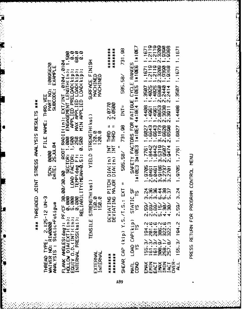
* D W~~(--Nmm wD** - -NNmaO -
w. o CD :c* m - - - -
N - . *WCD -OC)CD -
w~ ** Z ODW N--OCfl N1L C- 1- Z~ 0 W--N(Vm wOoz x a ""Ia LLC- -NNMOOC
OD ~ WZZ Vn -1 --- N- -- . JLJO aOX ~ ~ (~ .-. -.4ZZL
4T <E C) LLUu NNCO- 00 ~ 00 Ld co w< <U >-~ CS) LD()(S n,*v
WIZO0 I- w- -i DZ X U - Cn v (DN N mw 0 Z..LIw (1)*
*> -u Mo W- -- N
* < Z. i- 1b-4 r-. go(~ D-mco- cocmQ.CJ >xwc-J.J NoJ I- LLJ wwoDfl- 0
cf) :r wxLLJacL. 0 Z vaawm vc c
()W w aoi.xzw x -Z3''- 1 -1 0ii D O- NmmCfCDCD Ncf T WZ 0 WLW Nvv-No) N
(n bD.4 - CCC-CC CD O w w-W b -ii mg4 .. .
W) Ji <ZmLD WNN P-- N 0- -- N-* )- v ' M L NMf X-- I
LL D . - II UM~ -NN)N--i --- M z UI ZZD 'Irv -CDN (D.z CD3C 0 N 1im v N
c<* M) O . D - NWWW~fOOC N -(1C) G N 0 LL LD w 1= P-i -- zN(n . b-.4 ~ -4 -4 Wr w
W U.. U O~ >- - - wD LL M in--CN- inzw ZWr w' )i 11I <LW Ow wmU- U- MU)LLVZ woU, NVV-NN N 0Wl Cf< CD - O)OONN 0 M
O- I., -i -N-i i n i - Z- -
0 0- -< C . LL. 1COCOWCN vCL Z X W Nininqini N X:
00 in C r.- C u. i nL in <1W I m CD CD c LO ZZ 0~C0 Z 0 moo Zo 0. 1 NN<~ :J L Win i-i- U) <U O00LD)0
M ummi M-- 'Z I--wwwC-mni Mn CL
I -. JLL X~ U, > NNNL1)V N W~I- Id 0L WW 0U') L W U, L
* ~ CD + ~ .j.P. NWOCNWMi ND - 4 U~ It XD * -(f
* 3 d I~-c w p. .. -NNmmmi - I
.- MOD OfW'-L ,v U NN% NN, N C
>- -40c CLnC >-nC)-CD U,
M~ ~ ~ <E0C j - - - NN M~ ) 39 Z ZZ CL.<W>- Y~O>cX xx M, IW>: 4T J~ WUi ** <L ..J- 4ZZ -j
39LL XW- wwwU--U
A89
:4
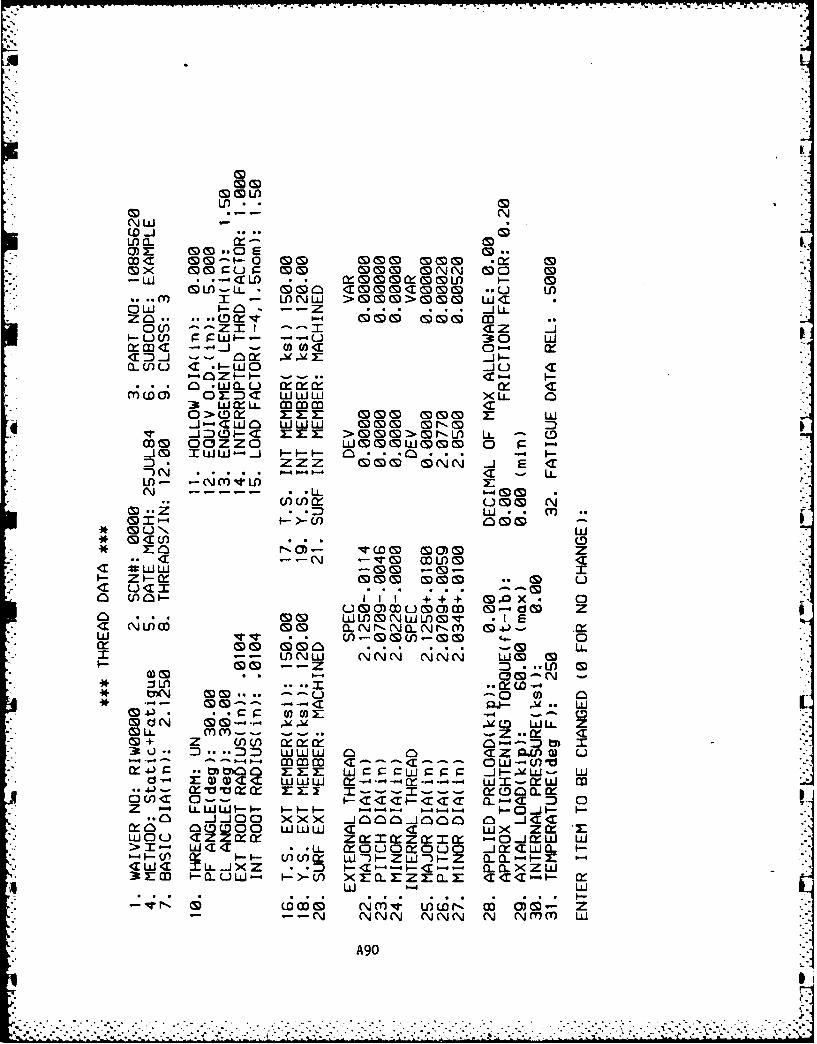
In.
NW -(D.
-W CL .cLI r
M ~ x S - LDW (S ~ CLJ GOW I- . . T -). . x * DL
G ~ ~ U) - LL MMn <m S DG -U L0(1 w ' 1 -'-- .Z . .. J
znC -- DX- 1-4 mo m0 -- Z cr I . x< z -
CD J-CW nix J -V.* ~C (D U .D -CE >- >-rLf -i C
(3 OEM<0 ww 0 U -3 ZZZ. mm CN 1
_j) -am W W ommJmNJ -- W --- F- F- CLi..C .
N~~. . .... 1L
*- m~ Zr *.
N -W -~ -tn - I -U- z'nt x *00 C
M D *L . .WW NMl~W~~U n *D W-I- ~ .
E 00 *.. mom zLIE -- o momJNN N LJ
*r lt 2C% -GS -0*(.. 30 0
Z x mom~ mom-. (S).C Cin U . CIJ 0 0x 0Z ) U
-~ ~ ~ U 0M M O m---- m~m - (do z~ G) tDC WWLOOV WI- En
**w..O vvX) 000000 04 0~Cr 0 0 00 LL CjWW Cj l C N LJ M~ W
G CO-- =Z . ..~ZIW 'J LJ L
G 3 - LUj-:1 n Nml inwr D O)- Z
M - -- CDN NN 0 N ) in
*~*.~~*7x . . . . . . . . . - .4 -1 4T Qj U .. W. . . . . .) *. . c l=~ W WE . -
CD . J Q* G -- -- 'w .u ) W
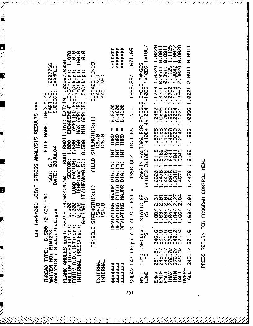
f W N--NVN-
co LD NOC:~0
(0 Lfl - (f, ** CD UCOW 0 ** W LLCDC--MfNO
NJ~ 0.... ZCW N--NVN-NO. *~-- -' Z 0 NO)O-0C
~~ ~ N '~<- orJ-Gao ...
* X Mr- - Q Wu Z 00i -0--G M
* ~ *oom WNaM >m NNww
5 ~ i ....cr.. .OOCC'I. - --- W-
w r -Crc- lvL'c- rNGON-rn rW -W goa z C YLi
Z no .- 0 Namo0)L- 0U) X LY CC. * f -UV m--- rn -
W- w 0 0 ZwoLI xm= N 0:* . .CA (I) <mow&( WNN wIi-C 0- "
- v~ moml-Wf X---- LL Co um * -ii U oC -- D C)
-i i--.- zz a)ZZ 'w -Wwvvv wD: 0 6-4- Is, LL 0 - - - VaM -
'1 ) 0.... L O - wLnrnmCD4r rnco CN 0 0LLf Wn w 1-r n-p -
U)0- -4 -- (D WI- ui- tmo -0-4- w n LL M ommmm -w
*f U, (1<' LI ) -1 -C MD CD Cw Nr -
- MOW-. -- 4 wvUm v 0oi .j-) .) .h- U
0 Uw cI-' t- 0 -- ~0 rn m CL - -o. - -nc rn Ln, V
I * --.. c ~J 1 * .
W m -~CD 0O M ZZ (D -- COLa U 0) (DCD G < Z V P-- N NN, N. 0I <r :J LL . - w LuL i---i u-) <rc u-)n-qc rnmv~o m a
w tm CJLIN J -j -- c< *w o w-> CLOOflO CIX( N N- I-, w P-4 *- 04.) LL (n> > --- N-
* - l CL... LLWUJ * 0
* 9 'q+ W . OOON) a)*~WM -* LOrn .---0 - .- - ............ z* * *N y)-.' Cf) W-C--CDGLt - l0--.J z Z - *- :D
3 ti- - c w P6 oL rnmmmrn rnm0-4 - -xzU, C- w~C
.. Czwf W1J-W u U% INN N, NWL -J rn.N Y a-)...
-0 (D - 0in CL <>- - L)LflCOWDW W d) U)
* 3 Z ZZ ***0.W>... Z.J-4w wLA *** ai .J )zZ-Xz-W-jW.-.' CI.JD - I-- * W I- Z C1UC-ULJ
CWW- W LO* Mu ZU w LLJW- -
A9 1
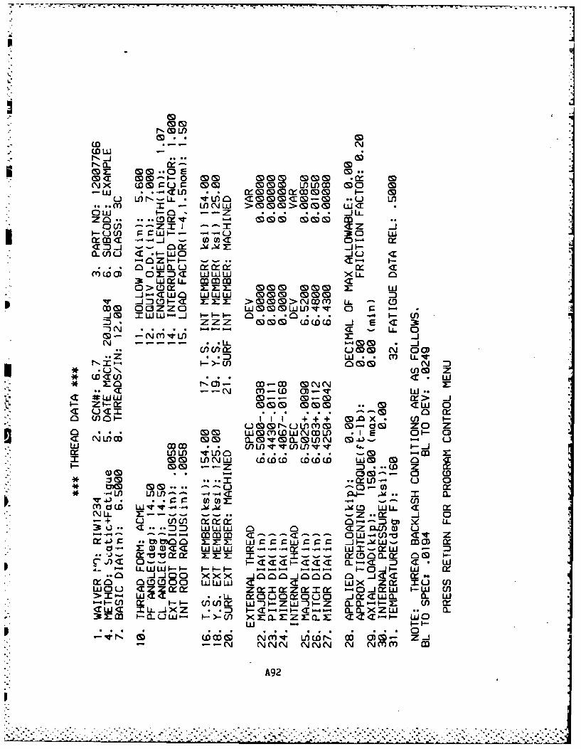
CD .- N0O -SNJN
ND w
0 CDD- 0 CLfl CD 0.L LI) C DM x C
M -C WfC\LJ W > () D C C C w 40 W -. .~ .* . . . j LL
0 U)~ -- ~I0 cxcoT ---- i - 0c~ 01) 4:
< -J~ W WWL Owu- n(~- uI <r~>~ Li.. -i C<
in Z <i..C) - CLD fCCL r
-J-<W.. n iW 0 moZN _j 0-- 00 N- < r G G> w .
_* CO 0If X. -- . n .. W
~- MV XwW -- jx> .-- - -- --cx- .
cn n 6. um N 000 (1)01 -I ++ MOX LL I
LO C1N (nOC C00 W~~W- O(O- C
* Vw 0,-& &0... X>.--
a (J) a .- I~ IO) I -; ; UCQXa D WOMW.-*- -IE 0~C LaL<N L CO -- S-s M CL V CL W 0-.-c .J
U) Cf)lw U) 0 fl . . L...L
CD (! V*** ) w~j W ( 0D o (D D wJ a) UCD4 (! -Zz D . ... ..- D
0) 0S ) C3tc CDW -x--~ ~ I -W -I.). CD~~cc zr. ..-- z--- M M.D0I.cx 0u
.0 WJO )(XX 400#-#< J. w..=cxo 0(0(000 UW o....jocc 0
0-4b-4 MM < --- <:n L--- CO O- CZV
-O -- < .T <r 4T a - . - W -
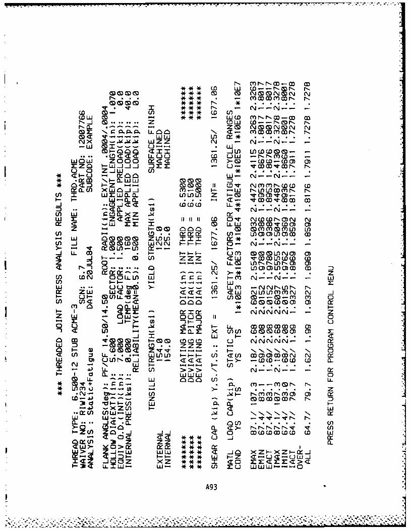
0 (S) S) G S) CDN C9 0 N ) N -~U ** (D W fl-Nn
r-~~ CL64 NOMNON NN.. .m.Lai - mmwmmrN NV- w I *** LN -r N. N- . -
CDj X M- U) Z* Z. N )W mm - ** W flN-c
N..J n <X= Z (W www-Nom0z << LLUUW N <r- M W
-x Wo CI) W* W.D()G
MN)< xw~ UJZZ 0 - N -- N-- -
W-CLC c-z -VWW W M.Jf C~0 _ *CDIx LL.U CDU N (n
won oooz cV n ~-w-owZM I-wZJ<CJ - Uo Ov N t DN0 ~
Uy w M 0 Z.L WI * ~ vW(f o- - . XW()- N-N) C-0 )0 D 0
0- 0~0.000 LDm xx X I)V C. U.- W-Q ... Xr--_j(00( LL O L* mm~
CD N >- *c z(n ( -N OO.~ W CmC N (/-W))LO(d
LI) 0- WD . --- ~ ~ IN) 0
-J I-- -W-- J 6-4 0) P-4 mmW C0 L(&-m M 0
.Y N--N-- -
zW ... OW-)~ >-O 0~C ~l-N~l
al c' LI) ECL -wo (.0CD0) a) X
W :3 0 0 S m ( - NNNN- - ZDI- a) Wo< ZU V o ,N ,1-
W M mmJ WI << CWOWWWa
~r N - N W b- b-40- U)I~ ~ > U > N N-N-
0 LL UJLLJinJ
* 'qT + _j m~ m -- mmDN N
* N-$ ty-- ' U) A - NMmNmC) 0) X41j a)--- Z - CcDCCDCN N-4j -XZCJ I -' a W
W W--cr--~CL... _.jZ < .0-U
0-4 a Z0 J ai- Cr 0j cr.CC(.( .-e Cr U) '1 ** Uz a.
3LL. W - W nu WWW-0-
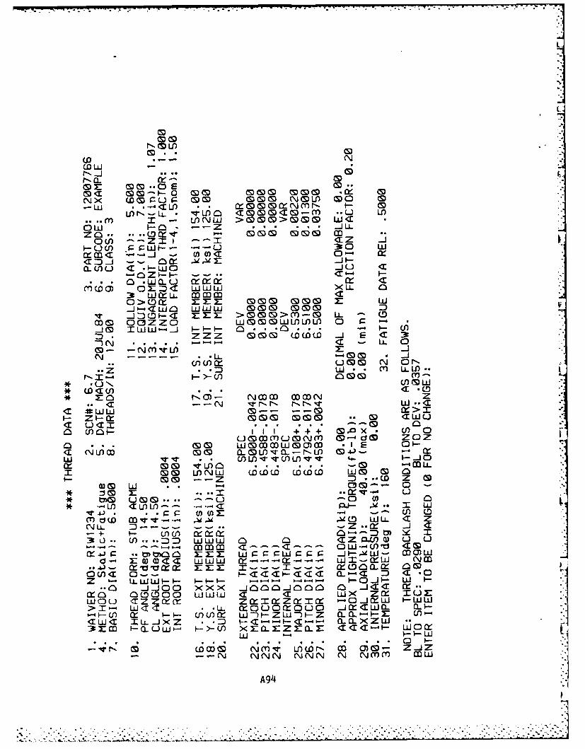
m LL
(D Lii
-LUI ..--'<CL) ZXG&cZNmr-N M-I) N - <Mom<M ~C-M *.L Lfl
ow L-L -- z (S; .6 6 j LL
0 ) '-Zt M: -IZ <rU (f) 9 CWU-- --- U 30 Lu
WM<:U C CWO.:) Ccm ioI-I- Ow C-
C)O) 02 c LAJLLJLI XU X0 x <3tt ww XLL 0
oJ-<w ww-J-4LJ LAJW 0 -4:T :M >mS() m M L
w & ozzo WMMOWMW~fW 0
-J (S) T .l . a . . ..- 10 .L
NS --
C~~~w. - -L--U)- L
* .: COCCI). . .m N 0 (D* r bEO NO) N.( D Z L
UN WLij in.- -S-G(Y
0 (101 III W+I (n )0LL
N 00 co .12 01-N4x NNql w .f.<.N~l
<r (0X:l0' W 4-
u~~~u!(i o--# do~ z Z0 ) wmmmim. . I cE. - 0 -
* 0& LO -q- v- 0) 0 LX- CD S) r _n n- - C
Wd W~-4- 'LD~ N (D LUU- OS Z
OUM W-- -- ZCI C O.. D l C !0.. ~) J..J0 XX ~ 0bOO 00- 01C O*
LO) 4a Z~ c Lr U)J~i - -LUW
N hi XLLJ)< *D C C - ' . W a
,c,,r4w- Ti mq <- --,I CD O)-OW 0 Z mJMC Z-N w N gN N Nmm 1r-a _ ,v MW
E 0 0 C a www x 4x-4. .
-4. .a-X NM
.. .
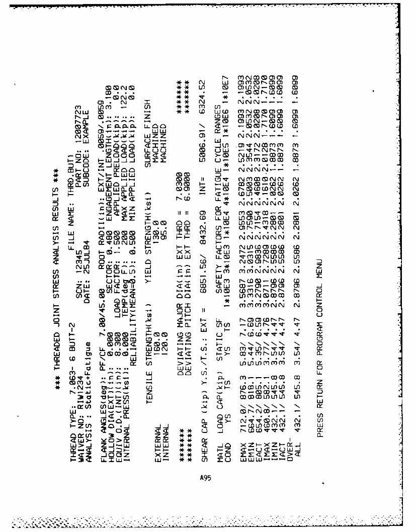
CD 0 N U) 0 0)LfN-M 0*CD CD -- (&N D ( (D0
0) N G .* N . .N.- . -
.J _j( .. .. Z 0 W ommNo)o 0r- . Z0 OOUN-0 0
m - : 3 P LLOO~ IN C - -WmrNWw wC < )-- LUW -L
N\JX Vf-~' L ) V NNN-- Z-- w~i ~ mmi_ U- Lii
-COo CII (0 _jU LO C) _Ncr rnmLo. <.4T C LLUU. (M LLW -'I NN Nr-t- -
-OW ZOCo 0CC a >&m NU)--m wI-Zo _ w _j.Jj - Z === u - OMrnMOM Mml 0 Z.J C/) *
*MI-L) LU-n NNN-* XC M HQ..CWWMCD D* < c - z -- CD (M (D T9' c ) ~ eJ N e~j
X CL 0 )(wo~J. Mfl H W-L am&m-C0( W() IT w WWO. (C, (Z wo -z N&COWNN N
H I-L~j-a-Q a~. *<- WU)V-0 0
(D _ *. -C C *-r-%. (DL ...*<0 a. NN N
CLo LU g(oa (z xw 1: - Z C C 4- 11 a, v~ rn&Vi--W.<C -.- m W LL0 Ww 000f-0
Z 0- HM D aO 0 LI)U-MCX Mf(f b4 - tD cr N f)- O) r-- NVN N N
Wl _j CMG WinO vH 0- NN('NNN N>- - V 01lU)f0-(_j LL CD .. * H NLIOO)C0 w< LAj Hx- < l XW N-Cr)CD MZ V: 0 Lww N Li0 VMnNULW w
'3 in 0. .. 0 .. .. )LDI UNLJ 0 XM - .JL) >** Z
CA -N OOLLU) LU r_ P O m MNNNN N LUW/ 6H- - ULU ... Mo~ >_ . LI) LL M N (0 -CW - COD (X~ ZLU WC 0)I 1C1 <aw W -0-00 0a _j
H F_ GWlLLdZ0- w. wo) W0ONN NN N 0C < Cl) < MM-CM m U)) (
0 QoaI .* .H CEM cr X_ MI rrnNN N Z
z V oLw- -u 11 i 0'1% _ N _ 4 >_ U -1 _uM Hx C - HLL NOO0WNN N
)~ CD z (L~ X Ml)CW -WU)NV Vq M:
O (M G)~ (5) ML UD NC0- - Z U
O D 0) MMO Zo I--, IN I NN Nll 0
LU m UMMOJ Xr-- CC * _ H>- Cfl'tTNOU U) 0..
I 1 LL X (f) > U)U)UO)O) m nH I d0 a.W * 0
in LL -. - LU On () -L
* D C.+ M--, . -r --- W* MnU ---- 0 0- > -n.......
",q4.) -XZU) H C LU.. Mwf MWL-LU u NNN N xW - NcD-a.. -1 C - C. U ........... U)>-c 0 D-O 0.a. aC>- NVVMNN N W)Hz ( i O..J J. <: 0 .- w~ornrn n LU
6-4C 0* C <J u _j N W V v Ox VZ ** Q.. a
W>_ ~ ~ **~l X fW>.J Z..J- w w <LjU ** C ..JC X-X Z HCQ jX-C C..i)H HH ** LHZ C-U'-UU-j
.JCC3 )<Za ** x CO mr~xz2>CH3 LLIUJ- w - W*U ru W LUL- - -0
A95
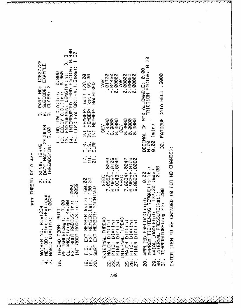
mNN LI m
r- CLJ)L ( WCDX W ! -- 0 E CD* ... J
N~~~~ x mDmcu -a C M o 0
(nn co *-w LL C oi T--q z T0C D u cD
U O wQ-U U :39 cico Mr< <wwj - w XiC 0
3 UJLI mmm I__j ~ ~ -,C WW W om m m
_j .D 0 - < rZ~ >MOO>M LL - Cmml( ocazzc woa0 nmm-
J~~zz mooJI---0* -Iz t-tD . .j . . c.<i
NI -N Lf - -rL-D
* >-~f .. * CDD
<r -- N mov 0r w<r ;;Ww CD-N N-0 X
- z - cr moo mo 0 uCz u41 a * . . --o n 1)0I I ;+ ; D~ 0
UNNMU--ILI 0-4do ZOD O.. LIJL)IW~MNN *1IE
w CD)0) * wCoo0)mwLoom '. 0
:E CDCDcow r--w. rDww WN DCat CD -Z CD CD
J iN .. -r . N--* r( bflf m -- u -0-0f
**j r (O-) *- - C !
mN r~-~-- z .'n w
3+ D (fl) (n af aIt -0 CO -- :D WWLU a a <z smri U
W a CLW-- -1-4- - - - l *- 4M-041 4
Z - U-t W *w 0o~ ru -jc~Q I-3rcfa I-Qu -j0 -- cn aan j0 a<O.EE~ - < C
>m- W LiiLL O u cc o -iXcwa
- U M owa w m U w z r* L- )- m Z-
- - NNNNN N N\MM Lii
A96
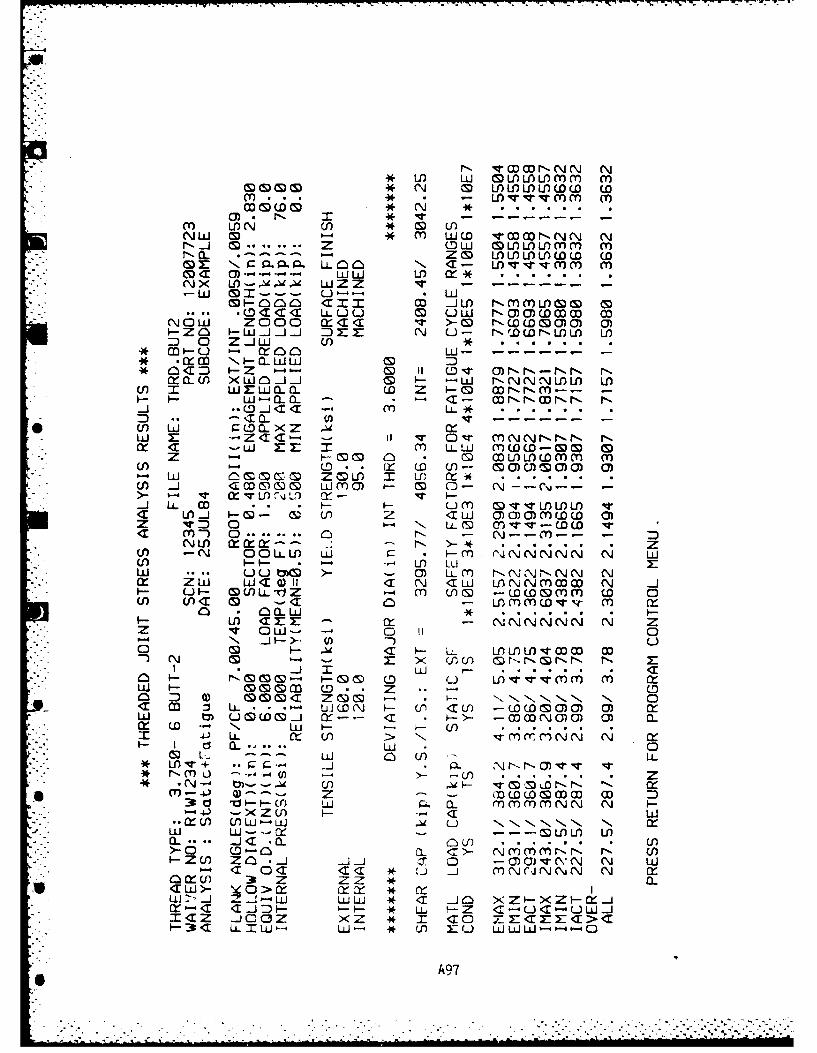
v OD 00 r-N N l* wD wL Mtu~r U rU)MC m
CD CDIS) M* N CD LA) L LLOCD D (Din... *v vM . -- im
Q3) Min LAN Uj *D CD U)NW 0 0- * in WCD rNNN NN. - . Z 0D w LflOlLOiM inr-. .----- 0-4 Z~ 0 MMO)U)C w
0. so LL~ n aCa- wvvv-(fm ina~ C)--4-- w w ) cl *NX x LLJZZ v
-~ - - -.J S -C.. U -- * LM -nnn am= cnJIm NMinLAM M
*(D aCCa LLL U U Ciw NC)C)CDM MNOW ZOOD xaa . - Nwwoo~o 0I-Zn - w !. j . DEZ N (uJ- NwflCNLAM wADO 0Z.!W U) **
* -XC Q- LdW(Sa<=C I-Z '-' (S 1 OV~ o)NN-N-N NxQU) xwn2J.! & I- -W N"NNNMflL L
(f) M wzrwa-ao CD Z- 0 WNr~n-- -I-I- W-Q.0 - a - cDNr-cNN N-
0-Ja 1 m Li..
wi Z -- ZaC- - il v - Dr nNNNN N0: <1 -WZzm LL W MWWC-M 0z M G) o . 0 LflMlCwiin i
U) 0- (ID. M~ CD (f) C~)CM0 ) C)w' Ci S S S S Z CDLO M LU) 0: 1
AT1 iX G) wS) C- Li o )M C)- N -- -r-,* _C n. -js a! U) - vW CnCDU) LI )Zi L- 0 a U OO)-CDCD 0
NLfl CkC C- .2N >*U) -Nr- OO.LI uJ- Ii N N N W-o1 -I-- -- 4 LO LUIu . W ... U M >- - C3) LLiCY NNNN N Nw ZW WC)l 11 N aw LANNinM N ...
I- c- MU)LLTIZ M MnU( wO~nnCU)l U)C <1 -C -annn'-~i
. 0C1.W * .* .M- Larm~ NNNNNN N Z
z v Ow- u'' 0IP-4 N .!I->-* Mf0 ND <[ L- X )f):r~N
-j M w r- Q:0 I- N o- '-Go oD u LO~iin iWI- M ~C D- Z o. z0in ) 0) M~~< (S a)NN a 0 S S
W U-C~ rz-- CC b-\- a -an(DC ) () C) 0.w 4) uL CD. ( C U c> a a) (x) N N (3 0-.- I C W
4J LL '- 0 0 U
-. ~ ~ (S *- NinU C)-O U)- .. )................* ~ ~ ~ ~ ~ ~ 0 VN V,-. ) ~ -~~LN
Y" -I--U 0 Eo C6. 1inininNN Nrj- t-< U V)-- CM - W--- -z--LfL I>-t cl -0 0.. C>- NCV) inNN N U
4-ZU Z.! 01 LIOi(N
0LU) 3A Z Z)CLU> aZ > clr *V)LO> .- W L J XIXI-
~~~-C~~~ N! I N-I * . Z C-j'UIz ... OC xZ in a Ca M NC i CN>N NI-C LIW-- W- a U) aWU~-s-e
a ck: ) 3t7CWSIC Xa l
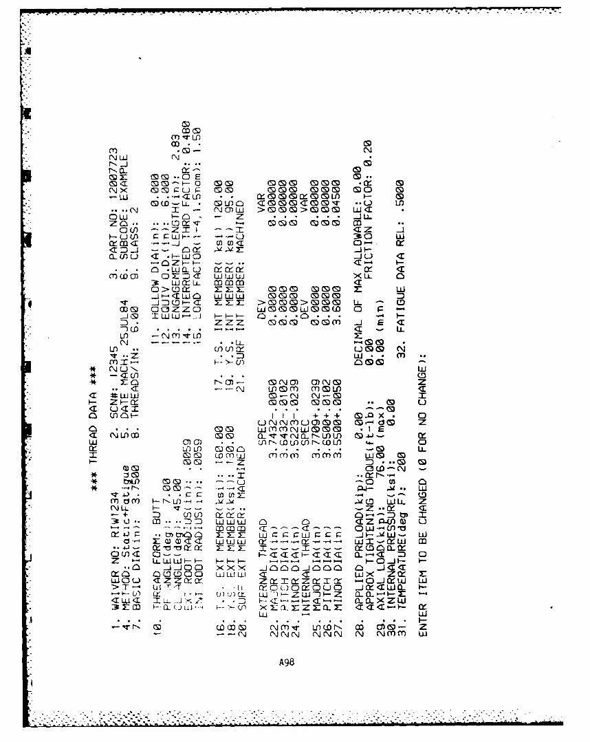
m c)
t-W * -Cf LCS) Y- 0GJ M WC0
NU( x o :-u -- so4( MO 3 0 GLmIJ *- -~ - -y l ()C)L)G
(CD .- L4 C4) Cf 1M00<[MC)V ) i
Q. UQ - COCC-- P- 0 o
3 U) ~ r-r-Ld-- 3 C L
c :--) OOC aa0
*C ZT -
C) - Lr CL L) X Ztc3:NL --- ~ **LL 4
Z) - -z mom OmmL CiE
C DC . . . .4TL
N LLI -I (9+ (.fXD
C Lfl OfN~Llf um-*T ULl C .. * .7LLJ.
0) - ONO*. ON* N - r) Q(fl- 0- S)U I
* U) LLJ O-N N0 Xz (flfl -r --.- On ()
<I: .ul & aJW rr MZ.f)
a * WJ00om .t)> IOJ Q E<I (JL) ZC N M , 4-NCL Z-M M -I..i~ Liw
.DJ S . . . .. * . . ...) L-
0-(S C3 (nD N - hO O- N
..................- .. . ._ 0 0 aNr A.-s- . . - C. .i z -1 .
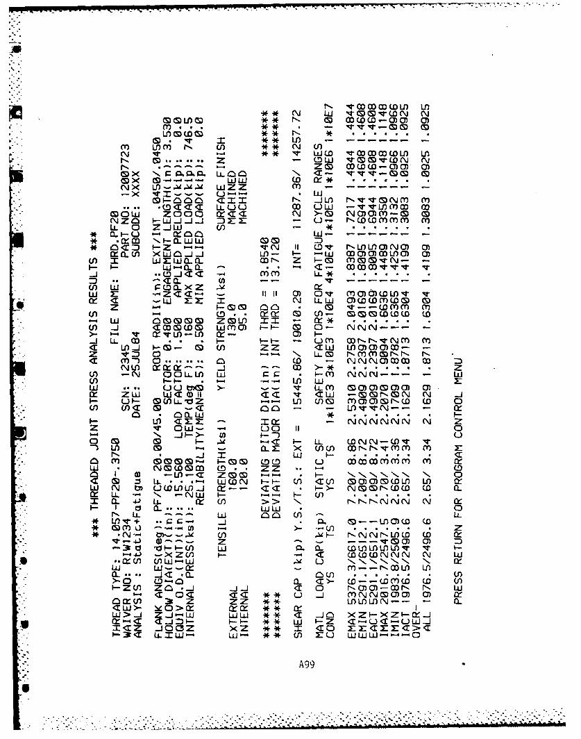
M~ ~ G cD CS WWW A LaM ~ * v .A . VV-CDN N
in.. **0M . .
M L (D * N *~ rww ** LA - --
z QLLV. C V( N(N* -.-- ZM 0 (oD(D - () () CY)
cp x N LA- 0 a <N - V-V'M M
N)( M v u LJ ZZ M i --- -x t - - -- - L±J
CIIN jMf NVVMNM Mn.CD C C LQU MO LUL -VVMinO M
Co D 0 zo C< N >- M NC)Cmin- 0NZO J-J -J.j DEM7 U L- NCDCini inM
-. LL 0 Z..JLL U)-CL O..-LU)OW- - -
U) M wx~wa..fl Z M- MMMVN--I- (L CLQ 6-4 a- MM VV
S. a. -* - -- - -~ -
w X: "Z<Cl- - 0iiC Ov inCO)CMV~ vof <i -W EX N LLLLW oww(oinD M
P-LA - cD. afQ C9 LA- M S M( D (D (D-w OMM zOtn X=- >
(n .J <1cOWCD ui~C M-- 0- NNN---
* .j LL wo * .I -- UMCf (nt -fNNM MC M _j I-M- 0 LA ZZ Clii wooCo- -tz V= 0........ LL - C'JNMMNCoo N
NW M-- J1 (-- NN OW w- * ZDLA 0 -N QOLL -1 W I-in NNN--- LL-) w(n -I 1- *-4 LAW w
w ... u typ >- -- v LLi M MOOMOM aC)*r Ck ZW WC 0) 1C cc Cliw -M(GNMN N ..J
I- 0- MALLVZ M- LA LAMiOMM)NCD w 0LA LAT M -C AT0 - -LAN-- W
Q- - a a- *........ I-Z V OWi- -4 00 I 1 0a- -. N i ..J-)- (0 u~O M CS - ~ C I-LL CDNN-CDV V
U) LA CL r.. x< LL (n NrN'wii in zN *U .. Ili .................. C
0n M MM- -M CDC u~ MMMoiini in Ofw (, (M (D(S) C LO- ZZ -- - (D
U') 0 -AC Z( M M 1- N "I N, 0M1 : LL - .- -' WCDN F-- LA < 1) ~c)C)mCD wA c
W N M L3CDALA. X-- CC .- I>- NMNWC wD a-x LL N 1- NW1 -N- w L ...AI a. 43. LL. Ix (LA NNNNNN N cr-
- L d - -ii * anL* n q+ a;-.- .. P1-LC CD-- o
* N- LA- NNNNOC CD OrV- -0 a)9---A zi P.V 0 CDALL0q~ I
4- -XZLA W-- WWCCNNN N Wj3 .cL OAaJ-UJ A u 1- N. N NNN, N xLii W--a:t in--NMML LAQ.._. <I JCQ. .......... .. .. . M>- D-M 0a. aC>- CD--wiC CD LA-Z ( l ZOj. aw C0 NC)C)-XN N wi
CI 0< C C ** -j J NNOOMC C) cX n3 Z ZZ **MMLN-- a-0.W>-Lii **-W w C -jO axzI-XZI-W-j
cr-C - =)** ui -Z a-'0C-UW-jICZ .JoCZ xZ C* 0 zI Ecxzr>C-3 C 11.1W- w - M*L ro WWiiW-- --
A99
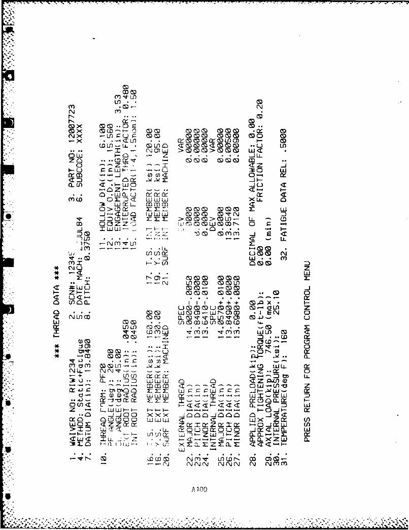
Lflm CS) N~
Nm
_x <X 'LI) Q G mx (DLO) I- G(D- L- (S)u >> &tS CwT0(DMITMM0 U
CL'i Z *.j *'
o --- z= ---- a- _u r LI-- --- U 30 WL
Qcm -cn _ () <r 0-4 CK
QCn U) .1T W JCJ 0 Ct
O* ac r: E LILJ L L
3 >~ mm3 cr rr - C S S)C)M X
_j= D _< EE 0 > 0&M- LL -
.J : IW Wil .__ . .0 ...- 4I -:0 0z I! s mm -i E -ci
ThLI -- "--. .- - - c - Li.)r- - N MTLDE
Lu L (J w U)CDU(m N
r moow.. m
* 4U Z*n -a a- W
I- Z9-I .. -0 -C
:1 CY X_ & &.4T -4 0o 00 (!Do)WN~c .ISN C
Mi cf (DlC)~ G (.oW. L
NI L N ~ N-- -I - .W __x
4.) 0C0- (!
*.%C- a a~n C- < 0 --
3U. 0..-oV www cJ X ZQ4AO (fWOEc zz a x- zim C----t-------C0-XW~ Z>T 'l e 1 L - 0 CQ) O)C QJW 0 L-JXC i f
a:n C-- - L I w- --- ) C-cz aaL-C xl
Cw< 0CD_ C z w -j - C CL a-X Z~ W (fWOE CZ~cxzCaICz0T2rCz CA.0- U
- -CN (NJNN NNN N Nmm
A 100


![[PPT]SCREW THREAD MEASUREMENT: - WordPress.com · Web view2016/02/10 · SCREW THREAD MEASUREMENT: Screw threads have to perform two functions namely Transmission of power and motion](https://img.pdfslide.us/doc/110x75/5b083b2c7f8b9a992a8bf8cc/pptscrew-thread-measurement-view20160210screw-thread-measurement-screw-threads.jpg)